WO2025041251A1 - Ensemble inducteur - Google Patents
Ensemble inducteur Download PDFInfo
- Publication number
- WO2025041251A1 WO2025041251A1 PCT/JP2023/030101 JP2023030101W WO2025041251A1 WO 2025041251 A1 WO2025041251 A1 WO 2025041251A1 JP 2023030101 W JP2023030101 W JP 2023030101W WO 2025041251 A1 WO2025041251 A1 WO 2025041251A1
- Authority
- WO
- WIPO (PCT)
- Prior art keywords
- terminal
- inductor assembly
- core
- terminals
- bent
- Prior art date
- Legal status (The legal status is an assumption and is not a legal conclusion. Google has not performed a legal analysis and makes no representation as to the accuracy of the status listed.)
- Pending
Links
Images


Classifications
-
- H—ELECTRICITY
- H01—ELECTRIC ELEMENTS
- H01F—MAGNETS; INDUCTANCES; TRANSFORMERS; SELECTION OF MATERIALS FOR THEIR MAGNETIC PROPERTIES
- H01F27/00—Details of transformers or inductances, in general
Definitions
- the present invention relates to an inductor assembly.
- Patent Document 1 discloses a dual inductor in which two inductors are integrated.
- a rectangular parallelepiped second core (21) is stacked on a rectangular parallelepiped first core (11).
- a second terminal (22) extends from the second core (21) to the lower surface of the first core (11).
- the second terminal (22) is fitted into a second recess (112), thereby stacking and integrating the two inductors.
- Patent Document 2 will be described later.
- a first terminal (12) or a second terminal (22) is disposed on each of the four sides of the dual inductor. Therefore, when multiple dual inductors are disposed side by side, or when the dual inductor is disposed side by side with other components, the multiple dual inductors, or the dual inductors and other components, must be sufficiently separated from each other in order to ensure an insulation distance. This creates the problem of a larger mounting board being required.
- the present invention was made in consideration of the above-mentioned problems, and provides an inductor assembly that can save space on the mounting board.
- the inductor assembly of the present invention is an inductor assembly having a first core with a first coil inside, and a second core that is different from the first core and contains a second coil, the second core is disposed on the first core, the inductor assembly has a plurality of side surfaces, each of the plurality of side surfaces of the inductor assembly includes a side surface of the first core and a side surface of the second core, each of a pair of first terminals that are electrically connected to the first coil protrudes from a side surface of the first core, and the inductor assembly
- Each of a pair of second terminals that are electrically connected to the second coil protrudes from a side surface of the second core and has a mounting portion that runs along the bottom surface and a standing portion that runs up from the mounting portion, the standing portion of one of the first terminals and the standing portion of one of the second terminals are formed on a first side surface of the inductor assembly, and the pair of first terminals and the pair of second terminals are not formed on a
- Such an inductor assembly has a second side on which the first terminal and the second terminal are not formed.
- the inductor assembly and other components can be placed on a mounting board with the second side of the inductor assembly in close proximity to other inductor assemblies or other components (collectively referred to as other components, etc.).
- the second side does not have the first terminal or the second terminal formed thereon, the inductor assembly and other components can be placed with the second side sufficiently close to the other components, etc. This allows space saving on the mounting board.
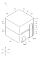
- FIG. 1 is a perspective view showing an example of an inductor assembly according to a first embodiment of the present invention
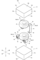
- FIG. 2 is an exploded perspective view of the inductor assembly according to the first embodiment.
- FIG. 2 is an exploded view of the inductor assembly according to the first embodiment, showing a perspective view from below.
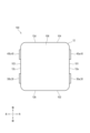
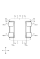
- FIG. 2 is a top view of the inductor assembly according to the first embodiment.
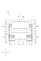
- FIG. 2 is a front view of the inductor assembly according to the first embodiment.
- FIG. 2 is a right side view of the inductor assembly according to the first embodiment.
- FIG. 2 is a bottom view of the inductor assembly according to the first embodiment.
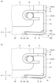
- Fig. 8(a) is an enlarged view of an example of the second terminal in Fig. 5.
- Fig. 8(b) is an enlarged view of another example of the second terminal in Fig. 5.
- the various components of the inductor assembly of the present invention do not need to be independent entities, and it is permitted that multiple components are formed as a single member, that one component is formed from multiple members, that one component is part of another component, or that part of one component overlaps with part of another component, etc.
- the manufacturing method of the inductor assembly of the present invention may be described using a number of steps described in a sequential order, but the order of the steps does not limit the order or timing of performing the steps. Therefore, when implementing the manufacturing method, the order of the steps may be changed to the extent that does not interfere with the content, and some or all of the timing of performing the steps may overlap with each other.
- the front-rear, left-right, top-bottom directions are defined as shown in the drawings. However, this is defined for convenience in order to easily explain the relative relationships between components, and does not limit the directions during manufacture or use of the product embodying the present invention.
- the top-bottom direction is the vertical direction with respect to the mounting board when the inductor assembly is mounted on the mounting board.
- the lower side (lower side) in the top-bottom direction refers to the mounting board side of the inductor assembly when the inductor assembly is mounted on the mounting board.
- the upper side is the opposite side of the lower side in the top-bottom direction.
- the top-bottom direction may or may not coincide with the vertical direction.
- the front-rear direction and the left-right direction may be collectively referred to as the lateral direction.
- the lateral direction may be the horizontal direction, but it does not have to be the horizontal direction.
- the term "flat surface” as used herein means a shape that is physically formed with a flat surface as a goal, and it is not necessarily required that the surface be a geometrically perfect flat surface.
- FIG. 1 is a perspective view showing an example of an inductor assembly 100 according to a first embodiment of the present invention.
- the inductor assembly 100 has a first core (first core 11) and a second core (second core 12).
- the first core contains a first coil (first coil 21).
- the second core contains a second coil (second coil 22).
- the second core is a core different from the first core.
- the second core is disposed on the first core.
- the inductor assembly 100 has a plurality of side surfaces 101 to 104.
- the plurality of side surfaces 101 to 104 in the inductor assembly include side surfaces 11a to 11d of the first core 11 and side surfaces 12a to 12d of the second core 12, respectively.
- the pair of first terminals 30 (30a, 30b) are electrically connected to the first coil 21.
- Each of the pair of first terminals 30 protrudes from a side surface (side surface 11a or side surface 11c) of the first core 11.
- Each of the pair of first terminals 30 has a mounting portion 32 and a standing portion 34.
- the mounting portion 32 is disposed along the lower surface 105 of the inductor assembly 100.
- the standing portion 34 stands upright relative to the mounting portion 32.
- the pair of second terminals 40 (40a, 40b) are electrically connected to the second coil 22.
- Each of the pair of second terminals 40 protrudes from a side surface (side surface 12a or side surface 12c) of the second core 12.
- Each of the pair of second terminals 40 has a mounting portion 42 and a standing portion 44.
- the mounting portion 42 is aligned along the lower surface 105 of the inductor assembly 100, and the standing portion 44 stands relative to the mounting portion 42.
- the rising portion 34 of one first terminal 30a and the rising portion 44 of one second terminal 40a are formed on a first side surface 101 of the inductor assembly 100.
- the pair of first terminals 30a, 30b and the pair of second terminals 40a, 40b are not formed on a second side surface 102 different from the first side surface 101 of the inductor.
- Patent Document 2 discloses an inductor assembly in which two cores (stainless alloy powder blocks (3)) are arranged side by side. The base (5) covers the upper surfaces of the two cores.
- the base (5) is useful for adsorbing the inductor assembly to a mounter when mounting the inductor assembly on a mounting board.
- the base (5) is also useful for integrating the two cores.
- the first core 11 and the second core 12 are arranged in the vertical direction.
- the upper surface 106 of the inductor assembly 100 is the upper surface of the second core 12 and has a predetermined area. Therefore, the upper surface 106 of the inductor assembly of this embodiment can be adsorbed by the mounter.
- the second terminal 40 extending from the upper second core 12 is fitted into the terminal recess 11e below the first core 11. The second core 12 and the first core 11 are combined and integrated by the second terminal 40.
- the inductor assembly 100 is an electronic component including two or more inductors.
- An inductor is an element having at least one coil and at least one core.
- An electronic component is incorporated into a part of an electronic circuit to form a part of an electric device.
- the inductor assembly 100 in this embodiment includes two or more inductors and does not include other elements (transformer, antenna, etc.). Although the inductor assembly 100 in this embodiment includes two inductors, the inductor assembly 100 may include three or more inductors. In addition, it is preferable that two or more inductors are integrated in the inductor assembly 100.
- two or more inductors are integrated means that the inductors are configured to be connected to each other so as not to be separated.
- the first core 11 (first inductor) and the second core 12 (second inductor) are connected by fitting the second terminal 40 into a terminal recess 11e formed on the lower surface 105 of the first core 11 as described later.
- the two inductors may be held by other members.
- the two inductors may be configured not to be separated by a mechanical structure.
- the two inductors may be configured to be bonded with an adhesive or the like so as not to be separated.
- the fact that the two inductors are integrated does not include the fact that the two inductors are bonded to the mounting board and do not separate from each other any further.
- the inductor assembly 100 has a first core 11 and a second core 12.
- the first core 11 is a core in a first inductor
- the second core 12 is a core in a second inductor.
- the core is a magnetic member made of a magnetic material. Examples of the magnetic material include ferrite.
- the core surrounds a coil described later and enters the coil radially inside, so that the core forms a closed loop as a whole. More specifically, the core of this embodiment is integrally formed by placing the coil and terminals (first terminal 30 and second terminal 40) in a mold and pouring a resin containing a magnetic material such as ferrite into the mold.
- the first inductor and the second inductor in the inductor assembly 100 of this embodiment are each a molded coil.
- the core may be configured as a plurality of separate members.
- the core has a flat, approximately rectangular parallelepiped shape.
- the shape of the bottom surface of the core is approximately square.
- the bottom surface of the first core 11 and the bottom surface of the second core 12 have approximately the same shape and dimensions.
- the second core 12 is placed on the first core 11 so that they overlap each other in a plan view.
- the first core 11 and the second core 12, which are approximately rectangular parallelepiped shaped, are arranged in the vertical direction, so that the inductor assembly 100 has an approximately rectangular parallelepiped shape.
- the upper surface of the first core 11 and the second core 12 are bonded by an adhesive (not shown). This prevents the first core 11 and the second core 12 from being misaligned.
- the adhesive may or may not be disposed between a terminal recess 12e (described later) of the second core 12 and the upper surface of the first core 11.
- the first core 11 and the second core 12 may simply be in contact (abutment) without being bonded by an adhesive.
- An engagement portion that engages the first core 11 and the second core 12 with each other may be provided to fix the relative positional relationship between the first core 11 and the second core 12.
- a recess or a protrusion may be provided on the upper surface of the first core 11 or the lower surface of the second core 12, respectively, and the recess and the protrusion may be engaged with each other.
- the inductor assembly 100, the first core 11, and the second core 12 may not be substantially rectangular parallelepiped in shape.
- the inductor assembly 100, the first core 11, and the second core 12 may be prisms whose bottom surfaces are polygonal other than rectangular.
- the bottom surface of each core of this embodiment is formed with a terminal recess 11e, 12e.
- the terminal recess 11e, 12e is a bottomed recess recessed upward from the bottom surface of the core.
- the terminal recess 11e, 12e is open downward and to the side (to the right or left in this embodiment). As shown in FIG. 5 , the ceiling surfaces of the terminal recesses 11 e and 12 e (the bottom surfaces of the terminal recesses 11 e and 12 e which are recessed upward and have a bottom) are inclined upward toward the inside of the inductor assembly 100 . As shown in FIG. 1, the first core 11 and the second core 12 each have a plurality of side surfaces. The first core 11 has a plurality of side surfaces 11a, 11b, 11c, and 11d. The second core 12 has a plurality of side surfaces 12a, 12b, 12c, and 12d.
- One of the side surfaces of the first core 11 is arranged so as to continue to one of the side surfaces of the second core 12.
- “arranged so that the surfaces continue to each other” means that the sides of the ends of the surfaces are arranged close to each other and are arranged on approximately the same plane.
- the surfaces may be partially separated from each other.
- one of the side surfaces 11a to 11d of the first core 11 and one of the side surfaces 12a to 12d of the second core 12 each form one of the side surfaces 101 to 104 of the inductor assembly 100.
- the side surface 11a of the first core 11 and the side surface 12a of the second core 12 form a first side surface 101 of the inductor assembly 100.
- the side surface 11b of the first core 11 and the side surface 12b of the second core 12 form a second side surface 102 of the inductor assembly 100.
- the side surface 11c of the first core 11 and the side surface 12c of the second core 12 form a third side surface 103 of the inductor assembly 100.
- the side surface 11d of the first core 11 and the side surface 12d of the second core 12 form a fourth side surface 104 of the inductor assembly 100.
- the inductor assembly 100 has a first coil 21 and a second coil 22 as coils.
- the first coil 21 is a coil in the first inductor
- the second coil 22 is a coil in the second inductor.
- the coil is formed by winding a coil wire.
- the coil wire is wound with the winding axis in the up-down direction, but this is not limited to this.
- the coil wire may be wound with the winding axis in the left-right direction or the front-back direction.
- the coil wire is made of a conductive material (e.g., a metal such as copper).
- the coil wire may be a round wire with a circular cross section, or a flat wire with a flat cross section (e.g., a quadrilateral or ellipse).
- Both ends of the coil wire are drawn out from the winding part of the coil.
- the ends of the coil wire may be drawn out from the winding part near the center in the thickness direction (vertical direction) of the winding part of the coil, or may be drawn out from the winding part at the upper or lower side in the thickness direction.
- both ends of the coil wire may be drawn out from the winding part at the same height (position in the vertical direction) or may be drawn out from the winding part at different heights. For example, both ends may be drawn out from the winding part near the center in the thickness direction of the winding part.
- one end may be drawn out from the winding part at the upper side in the thickness direction of the winding part, and the other end may be drawn out from the winding part at the lower side in the thickness direction.
- both ends of the coil wire are pulled out from the winding portion at two positions on either side of the winding portion, but the present invention is not limited to this and both ends of the coil wire may be pulled out from any positions.
- the end of the coil wire is electrically connected to a terminal (first terminal 30 or second terminal 40).
- a terminal first terminal 30 or second terminal 40
- the end of the coil wire forming the first coil 21 is electrically connected to the first terminal 30, and the end of the coil wire forming the second coil 22 is electrically connected to the second terminal 40.
- the end of the terminal inserted into the core is bent into a U-shape.
- the end of the terminal holds the end of the coil wire and sandwiches the end of the coil wire in the vertical direction.
- the end of the coil wire and the end of the terminal are joined by a method such as laser welding or resistance welding.
- the mode of electrical connection between the coil wire and the terminal is not limited to direct contact as described above.
- the coil wire and the terminal may be electrically connected via a separate member.
- the end of the coil wire may be wound around a winding terminal that is a separate member from the terminal, and the winding terminal and the terminal may be connected to each other, so that the coil wire and the terminal are electrically connected via the winding terminal.
- the coil wire and the terminal may also be integrally formed from the same member.
- the terminals are input/output terminals, and each inductor is connected to other electronic components or electric devices via the terminals.
- the terminal is made of a conductive material, such as a metal such as copper, and the terminal of this embodiment is formed by bending a plate-shaped conductive material.
- the terminals of this embodiment have embedded portions 39, 49, standing portions 34, 44 and mounting portions 32, .
- the embedded portion 39 is embedded in the first core 11 or the second core 12.
- the embedded portions 39, 49 are parts of the terminal embedded inside the core. In other words, a part of the terminal continuing from the embedded portion 39, 49 protrudes laterally (towards either the left or right direction) from the core.
- the embedded portion 39 is the end of the terminal that is conductive with the coil wire, and is also the base end. One end of the terminal that is conductive with the coil wire is called the base end, and the other end opposite to the one end is called the tip.
- the entire terminal may be disposed outside the core, and the terminal may not have the embedded portion 39, 49.
- the mounting portions 32 and 42 are parts of the terminals including a mounting surface that is grounded to the mounting board.
- the inductor assembly 100 is mounted by joining the mounting portions 32 and 42 to the mounting board by soldering or the like.
- the mounting portions 32 and 42 and the mounting surface are aligned with the lower surface 105 (the lower surface of the first core 11) of the inductor assembly.
- the mounting portions 32 and 42 and the mounting surface are aligned with the lower surface 105 of the inductor assembly 100 means that the mounting portions 32 and 42 and the mounting surface are substantially parallel to the lower surface 105 of the inductor assembly 100.
- the terminals are bent inward at the first bent portions 36 and 46, and the mounting portions 32 and 42 and the mounting surface are aligned close to the lower surface 105 of the inductor assembly 100.
- the mounting portions 32 and 42 are aligned with the ceiling surface of the terminal recess 11e. That is, the mounting portions 32 and 42 are substantially parallel to the ceiling surface of the terminal recess 11e.
- the inclination angle of the ceiling surface of the terminal recess 11e is different from the inclination angle of the mounting portions 32, 42 and are not completely parallel.
- the terminals may be bent outward at the first bent portions 36, 46, and the mounting portion 32 and the mounting surface may be disposed to the side of the inductor assembly 100 and along the lower surface 105 of the inductor assembly 100. 5 and 7, the mounting portions 32, 42 are disposed in the terminal recess 11e of the first core 11. In this embodiment, the mounting portions 32 of the first terminals 30 and the mounting portions 42 of the second terminals 40 that are arranged laterally are both disposed in one terminal recess 11e.
- one or more terminal recesses 11e may be formed in the bottom surface of the core in a number corresponding to the number of terminals, and one or more mounting portions 32, 42 of the terminals may be disposed in each terminal recess 11e.
- the rising portions 34, 44 are parts of the terminals that rise relative to the mounting portions 32, 42.
- the rising portions 34, 44 are located between the embedded portion (base end) and the mounting portion (tip end).
- the rising portions 34, 44 rising relative to the mounting portions 32, 42 means that the rising portions 34, 44 extend so as to cross the mounting portions 32, 42.
- the extending direction of the rising portions 34, 44 includes more directional components perpendicular to the extending direction of the mounting portions 32, 42 than the extending direction components of the mounting portions 32, 42. Even more preferably, the extending direction of the rising portions 34, 44 is approximately in the vertical direction.
- the rising portions 34, 44 are disposed along the side surfaces 101 to 104 of the inductor assembly 100.
- the rising portions 34, 44 may be in contact (abutment or pressure contact) with the side surfaces 101 to 104 of the inductor assembly 100, or may be spaced apart.
- the standing portions 34, 44 of each terminal are disposed laterally outward from the center of the inductor assembly 100 in the lateral direction (front-back direction) when viewed facing the plate surface (main surface) of the standing portions 34, 44 (when viewed in the left-right direction). This fixes the relative positional relationship between the first core 11 and the second core 12.
- the first core 11 is prevented from being misaligned with respect to the second core 12 so as to rotate about the vertical direction as a rotation axis.
- the upright portions 34, 44 have a substantially linear shape extending in the vertical direction. As shown in FIG.
- the upper part of the standing part 44 of the second terminal 40 may be curved toward the core (first core 11 and second core 12) (so as to approach the side surfaces 11a, 11c of the first core 11 and the side surfaces 12a, 12c of the second core 12 shown in FIG. 1). That is, the upper part of the standing part 44 of the second terminal 40 may be recessed toward the inside. This allows the second terminal 40 to hold the first core 11 and the second core 12 well.
- a part of the standing part 44 is in close contact with the side surface of the core (the side surfaces 11a, 11c of the first core 11 or the side surfaces 12a, 12c of the second core 12) without any gap.
- the entire standing part 44 may be separated from the side surface of the core.
- the upper part of the standing portion 44 of the second terminal 40 is a part of the second terminal 40 that is arranged above the first terminal 30 (particularly the second bent portion 38 of the first terminal 30).
- the upper part of the standing portion 44 of the second terminal 40 is a part of the second terminal 40 that is along the lower part of the side surfaces 12a, 12c (see FIG. 1) of the second core 12 and the upper part of the side surfaces 11a, 11c (see FIG. 1) of the first core 11.
- the lower part of the second terminal 40 (a part along the lower part of the side surfaces 11a, 11c of the first core 11) and the first terminal 30 may have a substantially linear shape or a curved shape closer to a linear shape. That is, the upper part of the standing portion 44 of the second terminal 40 may be curved more than the lower parts of the first terminal 30 and the second terminal 40.
- the curved shape of the second terminal 40 is exaggerated in FIG. 5 for convenience.
- the inductor assembly 100 may have a shape closer to a straight line than the curved shape shown.
- the second terminal 40 is bent at a substantially right angle at the second bent portion 48.
- the second terminal 40 may be bent at the second bent portion 48 so as to bulge slightly outward.
- the first terminal 30 and the second terminal 40 may have a generally linear shape as a whole.
- the terminals are bent at first bent portions 36, 46 so that the mounting portions 32, 42 are disposed below the inductor assembly 100.
- the first bent portions 36, 46 are located between the standing portions 34, 44 and the mounting portions 32, 42. That is, in this embodiment, the terminals are bent inward from the standing portions 34, 44 to the mounting portions 32, 42.
- the inward direction refers to the direction toward the inside of the inductor assembly 100.
- the first bent portions 36, 46 are bent in a curved shape. Instead of this embodiment, the first bent portions 36, 46 may be bent in an angular shape.
- the first bent portions 36, 46 are bent in a shape that follows the corner formed by the side surfaces 101, 103 and the lower surface 105 of the inductor assembly 100.
- the term "terminal is bent” includes not only a terminal that is bent to form a corner, but also a terminal that is curved in an arc and does not have a clear corner.
- the first bent portion 36, 46 is a part of the terminal having a larger curvature than the standing portion 34, 44 or the mounting portion 32, 42. Since the standing portion 34, 44 and the mounting portion 32, 42 are substantially linear, the portion of the terminal having a curved shape between the standing portion 34, 44 and the mounting portion 32, 42 is the first bent portion 36, 46.
- Each of the terminals is bent at the second bent portion 38, 48.
- the second bent portion 38, 48 is located between the embedded portion 39, 49 and the standing portion 34, 44. That is, in this embodiment, the terminal is bent downward from the embedded portion 39, 49 to the standing portion 34, 44.
- the second bent portion 38, 48 is bent in a curved shape.
- the second bent portion 38, 48 may be bent in an angular shape.
- the terminal is bent immediately after protruding from the core (first core 11 or second core 12) to form the second bent portion 38, 48.
- the second bent portions 38, 48 are parts of the terminal having a greater curvature than the standing portions 34, 44 or the embedded portions 39, 49. Since the standing portions 34, 44 are substantially linear, the second bent portions 38, 48 are the parts of the terminal that protrude from the core and have a curved shape between the standing portions 34, 44 and the base end of the terminal that is outside the core.
- the standing portion 34 of one first terminal 30a and the standing portion 44 of one second terminal 40a are formed on the first side surface 101 (on the same side surface).
- the standing portions 34, 44 being formed on the first side surface 101 means that the standing portions 34, 44 are arranged extending on the surface of the first side surface 101.
- the standing portions 34, 44 may be arranged on the first side surface 101 in contact (abutting or pressing) with the first side surface 101, or may be arranged on the first side surface 101 apart from the first side surface 101.
- the standing portions 34, 44 are formed on the surface of the inductor assembly 100 facing laterally.
- the side surfaces 101 to 104 along which the standing portions 34, 44 of the inductor assembly 100 are located are flat surfaces.
- a groove extending in the vertical direction may be formed in the side surfaces 101-104 of the inductor assembly 100, and at least a part of the standing portions 34, 44 may be embedded in the groove. That is, the standing portions 34, 44 may be formed on the bottom surface of the groove.
- the bottom surface of the groove is also part of the side surfaces 101-104 of the inductor assembly 100. 6, the rising portion 34 of the first terminal 30a and the rising portion 44 of the second terminal 40a are arranged along each other.
- the first terminal 30a and the second terminal 40a extend in substantially the same direction (up-down direction). Moreover, the first terminal 30a and the second terminal 40a are arranged side-by-side in the front-rear direction.
- the pair of first terminals 30a, 30b and the pair of second terminals 40a, 40b are not formed on a second side surface 102, which is one of the sides 101 to 104 of the inductor assembly 100 different from the first side surface 101. That is, the pair of first terminals 30a, 30b and the pair of second terminals 40a, 40b are not disposed on the second side surface 102.
- the second side 102 when viewed facing the second side surface 102, the entire second side surface 102 is exposed from the pair of first terminals 30a, 30b and the pair of second terminals 40a, 40b.
- the second side 102 is a side adjacent to the side 101, but is not limited thereto.
- the second side 102 may be a side not adjacent to the side 101.
- the second side surface 102 is a side surface facing the side surface 101 or a side surface adjacent to the side surface 101.
- the second side surface 102 is a side surface facing the first side surface 101 at 180 degrees, a side surface facing the first side surface 101 at 120 degrees, or a side surface adjacent to the first side surface 101.
- the second side surface 102 is a side surface facing the first side surface 101 at 180 degrees or a side surface facing the first side surface 101 at 90 degrees. This allows the inductor assembly 100 to be disposed in close proximity to other components disposed in the front, back, left, right, and right directions.
- the third side surface 103 is one of the side surfaces of the inductor assembly 100.
- the third side surface 103 faces the first side surface 101.
- the pair of first terminals 30a, 30b and the pair of second terminals 40a, 40b are not formed on the fourth side surface 104.
- the fourth side surface 104 is one of the side surfaces of the inductor assembly 100.
- the fourth side surface 104 faces the second side surface 102. This makes it possible to place other components closely on the opposing fourth side surface 104 in addition to the second side surface 102, thereby enabling the mounting board to be used in a more space-saving manner.
- first side surface 101 and the third side surface 103 are opposed to each other at an angle of 180 degrees, and the second side surface 102 and the fourth side surface 104 are also opposed to each other at an angle of 180 degrees.
- first side surface 101 and the third side surface 103 may be opposed to each other at an angle of 90 degrees, and the second side surface 102 and the fourth side surface 104 may also be opposed to each other at an angle of 90 degrees. That is, in the inductor assembly 100 having a quadrilateral bottom surface and four side surfaces, the first side surface 101 and the third side surface 103 may be adjacent side surfaces, and the second side surface 102 and the fourth side surface 104 may also be adjacent side surfaces.
- the standing portion 34 of the other first terminal 30b and the standing portion 44 of the other second terminal 40b may be formed on the first side surface 101, and the pair of first terminals 30a, 30b and the pair of second terminals 40a, 40b may not be formed on the third side surface 103 and the fourth side surface 104.
- all of the two standing portions 34, 34 of the pair of first terminals 30a, 30b and the two standing portions 44, 44 of the pair of second terminals 40a, 40b may be formed on the first side surface 101.
- the first terminals 30a, 30b and the second terminals 40a, 40b are arranged side by side in a predetermined arrangement direction (front-rear direction) on each of the first side surface 101 and the third side surface 103.
- the first terminal 30a and the other first terminal 30b are arranged on the same side (front side) in the arrangement direction (front-rear direction) with respect to the second terminal 40a or the other second terminal 40b.
- the first terminal 30a is arranged on the front side in the front-rear direction with respect to the second terminal 40a
- the other first terminal 30b is also arranged on the front side in the front-rear direction with respect to the other second terminal 40b.
- the first terminal 30 and the second terminal 40 may have different shapes, for example, as described later, and the heights of the mounting parts 32, 42 may differ slightly between the first terminal 30 and the second terminal 40. That is, the difference in height between the mounting parts 32, 32 of the pair of first terminals 30a, 30b and the mounting parts 42, 42 of the pair of second terminals 40a, 40b may be greater than the difference in height between the mounting parts 32, 32 of the pair of first terminals 30a, 30b, or the difference in height between the mounting parts 42, 42 of the pair of second terminals 40a, 40b.
- the grounding of each terminal to the mounting board is improved compared to the case where the first terminal 30a is arranged in front of the second terminal 40a and the first terminal 30b is arranged behind the second terminal 40b. Even if there is a large difference in height between the mounting portion 32 of the first terminals 30a, 30b and the mounting portion 42 of the second terminals 40a, 40b, the inductor assembly 100 can be tilted slightly forward or backward to allow the four terminals to be well grounded to the mounting board.
- the predetermined arrangement direction in which the first terminal 30 and the second terminal 40 are arranged laterally is the horizontal direction, and in particular, the direction along the first side surface 101 or the third side surface 103 (the side surface along which the first terminal 30 and the second terminal 40 are arranged).
- the predetermined arrangement direction of the first terminal 30 and the second terminal 40 arranged laterally with the first terminal 30 may be simply referred to as the arrangement direction.
- first terminal 30a and the other first terminal 30b are each arranged on the same side as one second terminal 40a or the other second terminal 40b, this means that when viewed from a specified direction (for example, when viewed in a plan view), the pair of first terminals 30a, 30b are arranged on the same side (front side) of the pair of second terminals 40a, 40b.
- the pair of first terminals 30a, 30b or the pair of second terminals 40a, 40b face each other. More specifically, the first terminals 30a, 30b or the second terminals 40a, 40b at least partially (in the present embodiment, substantially entirely) overlap each other when viewed from the side (viewed from the left-right direction).
- the central distance L1 is equal to or greater than the edge distance L2 (the sum of the first edge distance L2a and the second edge distance L2b).
- the edge distance L2 is the sum of the first edge distance L2a and the second edge distance L2b.
- the insulation distance between the second terminal 40 of the front inductor assembly 100 and the first terminal 30 of the rear inductor assembly 100 is maintained, while the insulation distance between the first terminal 30 and the second terminal 40 in each inductor assembly 100 (insulation distance within inductor assembly) is also maintained.
- the distance between the inductor assemblies includes the edge distance L2 and the width of the gap between the inductor assemblies 100, which will be described later. Therefore, by making the center distance L1 equal to or greater than L2, the distance between the inductor assemblies and the distance within the inductor assembly can be made substantially the same.
- the center distance L1 is the distance between the first terminals 30a, 30b and the second terminals 40a, 40b arranged side by side in the arrangement direction on the first side surface 101 or the third side surface 103. Specifically, the center distance L1 is the shortest distance in the lateral direction (front-rear direction) between the side end face of the first terminal 30a and the side end face of the second terminal 40a on the first side surface 101, or between the side end face of the first terminal 30b and the side end face of the second terminal 40b on the third side surface 103.
- the first edge distance L2a is the distance between the first end 107a of the first side surface 101 or the third side surface 103 and the first terminals 30a, 30b.
- the first end 107a is the end 107 of the first side surface 101 or the third side surface 103 in the arrangement direction, and is the end 107 of the first side surface 101 or the third side surface 103 close to the first terminals 30a, 30b.
- the end 107 is an edge in the front-rear direction of the first side surface 101 or the third side surface 103.
- the end 107 of the first side surface 101 is the side that is the boundary between the first side surface 101 and the second side surface 102, and the side that is the boundary between the first side surface 101 and the fourth side surface 104.
- the end 107 in the third side surface 103 is the side which is the boundary between the third side surface 103 and the second side surface 102, and the side which is the boundary between the third side surface 103 and the fourth side surface 104.
- the first end 107a in the first side surface 101 is the side which is the boundary between the first side surface 101 and the second side surface 102
- the first end 107a in the third side surface 103 is the side which is the boundary between the third side surface 103 and the second side surface 102.
- the distance between the first end 107a and the first terminals 30a, 30b is the shortest distance in the lateral direction (front-rear direction) between the first end 107a and the side end surfaces of the first terminals 30a, 30b.
- the second edge distance L2b is the distance between the second end 107b of the first side surface 101 or the third side surface 103 and the second terminals 40a, 40b.
- the second end 107b is the end 107 of the first side surface 101 or the third side surface 103 in the arrangement direction, and is the end 107 of the first side surface 101 or the third side surface 103 that is close to the second terminal.
- the second end 107b of the first side surface 101 is the side that is the boundary between the first side surface 101 and the fourth side surface 104
- the second end 107b of the third side surface 103 is the side that is the boundary between the third side surface 103 and the fourth side surface 104.
- the distance between the second end 107b and the second terminals 40a, 40b is the shortest distance along the lateral direction (front-rear direction) between the first end 107a and the side end surface of the second terminals 40a, 40b.
- the difference between the center distance L1 and the edge distance L2 is preferably smaller than the width dimension (the dimension in the lateral direction, particularly the front-rear direction) of the first terminal 30 or the second terminal 40. This ensures that the edge distance L2 is sufficient to ensure the insulation distance between adjacent inductor assemblies 100.
- the first edge distance L2a and the second edge distance L2b are equal to each other.
- the first edge distance L2a and the second edge distance L2b being equal to each other means that the first edge distance L2a is half or more of the second edge distance L2b and is equal to or less than twice the second edge distance L2b.
- the center distance L1 and the edge distance L2 may be equal to each other.
- center distance L1 and the edge distance L2 being equal to each other means that the center distance L1 is equal to or more than half the edge distance L2 and equal to or less than twice the edge distance L2.
- the center distance L1 may be smaller than the edge distance L2.
- the tip 42a of the mounting portion 42 of the second terminals 40a, 40b is disposed further inward of the inductor assembly 100 than the tip 32a of the mounting portion 32 of the first terminals 30a, 30b arranged side by side with the second terminals 40a, 40b.
- the first terminal 30 and the second terminal 40 are illustrated in Fig. 7 to further emphasize this configuration. That is, a tip distance L3, which will be described later, is illustrated larger than it actually is.
- the second terminal 40 extends from the second core 12 and is bent so as to embrace the first core 11, and holds the first core 11 together with the second core 12.
- the tip 42a of the second terminal 40 is disposed closer to the inside of the inductor assembly 100 than the tip 32a of the first terminal 30, so that the second terminal 40 can hold the first core 11 more satisfactorily.
- the second terminal 40 extends to a position higher than the first terminal 30, the load on the joint surface between the mounting portion 42 of the second terminal 40 and the mounting substrate is likely to be greater than the load on the joint surface between the mounting portion 32 of the first terminal 30 and the mounting substrate. If the tip 42a of the second terminal 40 is positioned further inward in a plan view, the ground surface between the second terminal 40 and the mounting substrate becomes larger. As a result, the second terminal 40 is more firmly joined to the mounting substrate, and the durability of the joint surface between the second terminal 40 and the mounting substrate against loads is improved.
- the tip 32a, 42a of the mounting portion 32, 42 is an end of the mounting portion 32, 42 opposite the side continuing to the upright portion 34, 44.
- the tip 32a, 42a of the mounting portion 32, 42 is an end on the inside of the inductor assembly 100 in the mounting portion 32, 42 when viewed in a plan view.
- the inside of the inductor assembly 100 when viewed from a specific direction is the direction from the outer edge of the inductor assembly 100 toward the center of the inductor assembly 100 when the inductor assembly 100 is viewed from the specific direction.
- the tip 42a of one second terminal 40a is disposed to the left of the tip 32a of one first terminal 30a.
- the tip 42a of the other second terminal 40b is disposed to the right of the tip 32a of the other first terminal 30b.
- the area of the mounting portion 42 of one second terminal 40a is larger than the area of the mounting portion 32 of one first terminal 30a.
- the area of the mounting portion 42 of the other second terminal 40b is larger than the area of the mounting portion 32 of the other first terminal 30b.
- the area of the mounting portions 32, 42 may be the area of the mounting portions 32, 42 when facing the mounting portions 32, 42, or may be the area of the mounting portions 32, 42 when viewed from below.
- the tip 42a of the second terminal 40 is preferably disposed inside the inductor assembly 100 from the tip 32a of the first terminal 30 by a length equal to or greater than the thickness dimension of the first terminal 30 or the second terminal 40. That is, the distance (tip distance L3) between the tip 42a of the second terminal 40 and the tip 32a of the first terminal 30 in the extension direction (left-right direction) of the mounting parts 32, 42 is preferably equal to or greater than the thickness dimension of the first terminal 30 or the second terminal 40 (particularly the mounting parts 32, 42). This allows the area of the mounting part 42 of the second terminal 40 to be sufficiently large.
- the tip 32a of the first terminal 30 may be disposed further inside the inductor assembly 100. That is, the tip 42a of the second terminal 40 may be disposed inside the inductor assembly 100 from the tip 32a of the first terminal 30 by a length equal to or less than the thickness dimension of the first terminal 30 or the second terminal 40. That is, the tip distance L3 may be the same as or smaller than the thickness dimension of the first terminal 30 or the second terminal 40 .
- the second terminal 40 is bent at two points (bending points 46a, 46b) in the first bent portion 46.
- the crack is likely to stop at the bending points 46a, 46b and their vicinity.
- the bonding between the second terminal 40 and the solder is improved. Note that, for convenience, in Fig. 8(a) and Fig. 8(b), the bending shape at the first bending portion 46 of the second terminal 40 is exaggerated compared to the actual shape. In reality, the bending shape at the first bending portion 46 of the second terminal 40 may be closer to the bending shape at the first bending portion 36 of the first terminal 30.
- the bending points 46a and 46b are the centers of particularly steeply bent portions in the first bent portion 46. That is, there are two portions (portions that bend more steeply than other portions) that have a smaller radius of curvature than other portions (portions in the vicinity of the bending points 46a and 46b, such as the intermediate portion 46c) in the first bent portion 46 of the second terminal 40.
- the bending centers of the two portions or portions including the vicinity of the centers are the bending points 46a and 46b.
- the two bending points 46a, 46b are spaced apart from each other.
- An intermediate portion 46c sandwiched between the spaced apart bending points 46a, 46b is either linear or has a larger curved shape than the bending points 46a, 46b and their vicinity.
- the radius of curvature of the second terminal 40 at the bending point 46b on the tip side is smaller than the radius of curvature of the second terminal 40 at the bending point 46a on the base side. That is, the second terminal 40 is bent more steeply at the bending point 46b on the tip side than at the bending point 46a on the base side.
- This allows a larger mounting surface, which is a flat surface, in the mounting portion 42 to be secured. As a result, the bonding between the mounting portion 42 and the mounting board is improved.
- the radius of curvature of the second terminal 40 at the bending point 46b on the tip side may be larger than the radius of curvature of the second terminal 40 at the bending point 46a on the base side.
- the second terminal 40 may be bent into a curved shape larger at the bending point 46b on the tip side than at the bending point 46a on the base side. This allows the stress on the second terminal 40 applied at the bending point 46a on the tip side to be well alleviated.
- the bending angle of the second terminal 40 at the bending point 46b on the tip side is larger than the bending angle of the second terminal 40 at the bending point 46a on the base side. That is, the minimum angle between the approximate extension direction of the intermediate portion 46c and the extension direction of the mounting portion 42 is smaller than the minimum angle between the approximate extension direction of the intermediate portion 46c and the standing portion 34. With this configuration, the intermediate portion 46c is inclined at an angle of less than 45 degrees with respect to the horizontal.
- the intermediate portion 46c is disposed closer to the mounting substrate, so that the bonding between the intermediate portion 46c and the mounting substrate is improved, and the inductor assembly 100 is more properly fixed to the mounting substrate.
- the first terminal 30 is bent at one location at the first bent portion 36.
- the first terminal 30 may be bent at two or more locations at the first bent portion 36.
- the first bent portion 46 of the second terminal 40 is closer to the first core 11 than the first bent portion 36 of the first terminal 30. More specifically, when viewed in the arrangement direction (front-rear direction) of the first terminal 30 and the second terminal 40, the middle portion 46c is closer to the first core 11 than the bending center of the first bent portion 36 of the first terminal 30. As a result, the second terminal 40 is bent at the first bent portion 46 so as to be closer to the first core 11. As a result, the second terminal 40 can hold the first core 11 better.
- the second terminal 40 does not have two or more bending points 46a, 46b and is curved more than the first terminal 30, the bending center of the first bent portion 46 of the second terminal 40 is closer to the first core 11 than the bending center of the first terminal 30.
- the radius of curvature of the first bent portion 46 of the second terminal 40 may be larger than the radius of curvature of the first bent portion 36 of the first terminal 30 arranged side by side with the second terminal 40.
- the bent shape of the first terminal 30 or the second terminal 40 as described above may be formed by applying different magnitudes of force to each terminal or by applying stress to different parts of each terminal. Since the second terminal 40 is not bent as sharply as the first terminal 30, the stress applied to the second terminal 40 can be more effectively alleviated. Therefore, the second terminal 40 is more firmly fixed to the mounting substrate.
- a larger space is created between the mounting substrate and the first bent portion 46 of the second terminal 40, which has a larger radius of curvature, compared to the space between the first terminal 30 and the mounting substrate. Therefore, more solder can be accumulated between the second terminal 40 and the mounting substrate, and the second terminal 40 and the mounting substrate can be more firmly joined. This allows the second terminal 40, which is more susceptible to load than the first terminal 30, to be more firmly fixed to the mounting substrate.
- the second terminal 40 may be bent at the first bent portion 46 into a circular arc shape, or may be bent into a curved shape with a non-constant radius of curvature, such as an elliptical arc shape.
- the radius of curvature of the first bent portion 46 of the second terminal 40 being larger than the radius of curvature of the first bent portion 36 of the first terminal 30 means, for example, that the maximum value of the radius of curvature of the first bent portion 46 of the second terminal 40 is larger than the radius of curvature of the first bent portion 36 of the first terminal 30.
- the radius of curvature at the tip or base end of the first bent portion 46 of the second terminal 40 may be larger than the radius of curvature at the tip or base end of the first bent portion 36 of the first terminal 30.
- the distance between the base end and the tip of the first bent portion 46 of the second terminal 40 (the distance between the base end and the tip on a straight line connecting the base end and the tip) may be larger than the distance between the base end and the tip of the first bent portion 36 of the first terminal 30.
- the radius of curvature at the tip end of the first bent portion 46 of the second terminal 40 is larger than the radius of curvature at the base end of the first bent portion 46. This allows the first bent portion 46 of the second terminal 40 to be disposed so as to be closer to the mounting board, thereby improving the bonding between the first bent portion 46 and the mounting board.
- the angle formed between the standing portion 44 and the mounting portion 42 at the first bent portion 46 of the second terminal 40 is smaller than the angle formed between the standing portion 34 and the mounting portion 32 at the first bent portion 36 of the first terminal 30 arranged laterally next to the second terminal 40.
- the mounting portion 42 of the second terminal 40 may be inclined at a larger inclination angle relative to the lateral direction (or relative to the lower surface 105 of the inductor assembly 100) than the mounting portion 32 of the first terminal 30.
- the inclination angle of the mounting portions 32, 42 relative to the lateral direction refers to the minimum angle formed between the lateral direction and the mounting portions 32, 42.
- the angle formed between the standing portion 44 and the mounting portion 42 at the first bent portion 46 of the second terminal 40 may be greater than the angle formed between the standing portion 34 and the mounting portion 32 at the first bent portion 36 of the first terminal 30 arranged horizontally to the second terminal 40.
- the tip 42a of the second terminal 40 is disposed above the tip 32a of the first terminal 30. More specifically, the tip 42a of the second terminal 40 is closer to the first core 11 (particularly the ceiling surface of the terminal recess 11e) than the tip 32a of the first terminal 30. That is, the inclination angle of the mounting portion 42 of the second terminal 40 with respect to the horizontal direction is larger than the inclination angle of the ceiling surface of the terminal recess 11e with respect to the horizontal direction. Also, as described above, the inclination angle of the mounting portion 42 of the second terminal 40 with respect to the horizontal direction is larger than the inclination angle of the mounting portion 32 of the first terminal 30 with respect to the horizontal direction.
- the inductor assembly 100 has the above-mentioned configuration in a natural state before the inductor assembly 100 is mounted on a mounting board. It is not necessary for the first terminal 30 and the second terminal 40 to have the above-mentioned configuration when the inductor assembly 100 is mounted on a mounting board.
- at least the tips 32a, 42a (or tips including the vicinity of the tips 32a, 42a) of the first terminal 30 and the second terminal 40 are disposed inside the terminal recess 11e. In other words, the tips 32a, 42a or tips of the first terminal 30 and the second terminal 40 are disposed above the lower surface 105 (lowest surface) of the first core 11.
- the tip 32a or tip of the first terminal 30, or the tip 42a or tip of the second terminal 40 may protrude downward from the lower surface 105 (lowest surface) of the inductor assembly 100.
- the lowest point of the first bent portion 46 of the second terminal 40 is disposed lower than the lowest point of the first bent portion 36 of the first terminal 30.
- the first bent portion 46 of the second terminal 40 is disposed so as to be closer to the mounting board than the first bent portion 36 of the first terminal 30. Note that it is sufficient for the inductor assembly 100 to have the above-mentioned configuration in a natural state before the inductor assembly 100 is mounted on a mounting board.
- first terminal 30 and the second terminal 40 it is not necessary for the first terminal 30 and the second terminal 40 to have the above-mentioned configuration when the inductor assembly 100 is mounted on a mounting board.
- at least a part of the first bent portion 36 of the first terminal 30 and at least a part of the first bent portion 46 of the second terminal 40 are disposed to protrude downward from the lower surface 105 (lowest surface) of the inductor assembly 100.
- the lowermost portion of the first bent portion 36 of the first terminal 30 or the lowermost portion of the first bent portion 46 of the second terminal 40 may be at the same height as the lower surface 105 (lowest surface) of the inductor assembly 100.
- the tip 42a of the mounting portion 42 of the second terminal 40 is in contact with the lower surface 105 of the inductor assembly 100.
- the tip 32a of the mounting portion 32 of the first terminal 30 is spaced from the lower surface 105 of the inductor assembly 100.
- the tip 42a of the second terminal 40 comes into contact with the lower surface of the inductor assembly 100 (the bottom surface of the first core 11), thereby allowing the second terminal 40 to better hold the first core 11 and the second core 12.
- the tip 32a of the first terminal 30 is spaced from the lower surface 105 of the inductor assembly 100, so that the mounting portion 32 of the first terminal 30 has springiness without interfering with the inductor assembly 100. This allows the mounting portion 32 of the first terminal 30 to deform in accordance with the mounting substrate when the inductor assembly 100 is mounted on the mounting substrate, thereby allowing the inductor assembly 100 to be mounted on the mounting substrate well.
- the tip 42a of the second terminal 40 may be pressed against the lower surface 105 of the inductor assembly 100 (the tip 42a may bias the lower surface 105 upward), or may simply abut against the lower surface 105 of the inductor assembly 100.
- the tip 42a of the second terminal 40 may also be fitted inside the first core 11. That is, the tip 42a of the second terminal 40 and its vicinity (the tip portion including the tip 42a) may be disposed within the envelope volume of the first core 11. By having the tip portion of the mounting portion 42 bite into the first core 11, the second terminal 40 can better hold the first core 11.
- the radius of curvature of the second bent portion 48 of the second terminal 40 is smaller than the radius of curvature of the second bent portion 38 of the first terminal 30 that is arranged next to the second terminal 40.
- the second terminal 40 is bent sharply at a right angle in the second bent portion 48 while being substantially in contact with the side surfaces 12a, 12c of the second core 12 (bent so as to be close to and along the side surfaces 12a, 12c of the second core 12).
- the second bent portion 38 of the first terminal 30 protrudes slightly outward from the side surfaces 11a, 11c of the first core 11 and then curves gently toward the side surfaces 11a, 11c.
- the gap between the second bent portion 48 of the second terminal 40 and the side surfaces 12a, 12c of the second core 12 is smaller than the gap between the second bent portion 38 of the first terminal 30 and the side surfaces 11a, 11c of the first core 11.
- the difference between the radius of curvature at the second bent portion 48 of the second terminal 40 and the radius of curvature at the second bent portion 38 of the first terminal 30 is exaggerated for convenience. In reality, the difference may be smaller than the difference shown.
- the second bent portion 38 of the first terminal 30 protrudes further outward from the inductor assembly 100 than the second terminal 40 (particularly the second bent portion 48 thereof), but this is not limited thereto.
- the second bent portion 38 of the first terminal 30 may be located at the same position as the second bent portion 48 of the second terminal 40 in the left-right direction. For example, when bending the first terminal 30 or the second terminal 40 at the second bent portion 38, 48, different magnitudes of force may be applied or stress may be applied to different parts of the terminal to form the bent shape of the first terminal 30 or the second terminal 40 as described above.
- the second bent portion 38 of the first terminal 30 may be bent at a right angle or at an angle exceeding a right angle, while the second bent portion 48 of the second terminal 40 may be bent at an acute angle (so that the standing portion 44 tapers downward).
- the bending angle of the second bent portion 48 is slightly widened to a right angle, and the standing portion 44 can be brought into intimate contact with the side surface of the core.
- the second terminal 40 is better aligned with the second core 12 (especially the part near the second bent portion 48). This enables the second terminal 40 to hold the first core 11 and the second core 12 in a better manner.
- the first terminal 30 and the second terminal 40 may be bent at the second bent portions 38, 48 into a circular arc shape, or may be bent into a curved shape with a non-constant radius of curvature, such as an elliptical arc shape.
- the radius of curvature of the second bent portion 38 of the first terminal 30 is larger than the radius of curvature of the second bent portion 48 of the second terminal 40, for example, means that the maximum value of the radius of curvature of the second bent portion 38 of the first terminal 30 is larger than the radius of curvature of the second bent portion 48 of the second terminal 40.
- the radius of curvature at the tip or base end of the second bent portion 38 of the first terminal 30 may be larger than the radius of curvature at the tip or base end of the second bent portion 48 of the second terminal 40.
- the distance between the base end and the tip of the second bent portion 38 of the first terminal 30 (the distance between the base end and the tip on a straight line connecting the base end and the tip) may be larger than the distance between the base end and the tip of the second bent portion 48 of the second terminal 40.
- the present invention is not limited to the above-described embodiment, but includes various modifications and improvements as long as the object of the present invention is achieved. The following modifications can be combined as appropriate.
- the bending shape of the first bent portion 46 of the second terminal 40 is not limited to the above-mentioned shape.
- the second terminal 40 may be bent at three or more points at the first bent portion 46.
- the second terminal 40 may be bent at the first bent portion 46 so that a part or the entire first bent portion 46 has a wave shape.
- the radius of curvature of the first bent portion 46 may be the radius of curvature of a local curved portion that forms the wave shape, or the radius of curvature of the entire curved shape of the first bent portion 46 ignoring the wave shape may be the radius of curvature of the first bent portion 46.
- the method for forming the bent shape of the terminal described in this embodiment is not limited to the method described in this embodiment.
- the bent shape of the terminal described in this embodiment may be formed using a method other than that described in this embodiment.
- An inductor assembly having a first core with a first coil therein, and a second core different from the first core and containing a second coil therein, the second core is disposed on the first core, the inductor assembly having a plurality of sides; each of the plurality of side surfaces of the inductor assembly includes a side surface of the first core and a side surface of the second core; Each of a pair of first terminals electrically connected to the first coil includes: protruding from a side surface of the first core, a mounting portion that is disposed along a lower surface of the inductor assembly and a rising portion that rises from the mounting portion; Each of a pair of second terminals electrically connected to the second coil includes: protruding from a side surface of the second core, A mounting portion along the lower surface and an upright portion upright relative to the mounting portion, the raised portion of one of the first terminals and the raised portion of one of the second terminals are formed on a first side surface of the inductor
- the other first terminal and the other second terminal are formed on a third side face of the inductor assembly, the third side face being opposed to the first side face;
- the first terminal and the second terminal are arranged side by side in a predetermined arrangement direction, An inductor assembly as described in (2), wherein each of the one first terminal and the other first terminal is arranged on the same side in the arrangement direction relative to the one second terminal or the other second terminal.
- (3-1) An inductor assembly described in (3), in which a pair of first terminals or a pair of second terminals at least partially overlap each other when viewed from the side.
- (4) An inductor assembly as described in (3), wherein the distance between the first terminal and the second terminal arranged horizontally in the arrangement direction on the first side or the third side is the same as or greater than the sum of the distance between the first terminal and an end of the first side or the third side in the arrangement direction that is closest to the first terminal, and the distance between the second terminal and an end of the first side or the third side in the arrangement direction that is closest to the second terminal.
- (5-1) An inductor assembly described in (5), in which the distance between the tip of the second terminal and the tip of the first terminal in the extension direction of the mounting portion is the same as or greater than the thickness dimension of the first terminal or the second terminal.
- (6) The inductor assembly described in (5), wherein the second terminal is bent at two points in the first bend portion.
- (6-1) An inductor assembly described in (6), in which the first bent portion of the second terminal is closer to the first core than the first bent portion of the first terminal.
- (6-2) An inductor assembly described in (6), in which the radius of curvature of the second terminal at the bend point on the tip side of the second terminal is smaller than the radius of curvature of the second terminal at the bend point on the base side of the second terminal.
- Each of the first terminal and the second terminal is bent at a second bent portion located between the upright portion and an embedded portion embedded in the first core or the second core, An inductor assembly described in any one of (3) to (9), wherein the radius of curvature of the second bent portion of the second terminal is smaller than the radius of curvature of the second bent portion of the first terminal adjacent to the second terminal.
- An inductor assembly wherein a tip of the second terminal is positioned higher than a tip of the first terminal.
- An inductor assembly, wherein the second bent portion of the second terminal is positioned lower than the first bent portion of the first terminal.
- An inductor assembly, wherein an upper portion of the standing portion of the second terminal is curved more toward the second core than a lower portion of the standing portion of the first terminal.
Landscapes
- Engineering & Computer Science (AREA)
- Power Engineering (AREA)
- Coils Or Transformers For Communication (AREA)
Abstract
Chaque borne d'une paire de premières bornes (30) comporte une partie de montage et une partie verticale (34). La partie de montage s'étend le long d'une surface inférieure (105) d'un ensemble inducteur (100). La partie verticale (34) est verticale par rapport à la partie de montage. Chaque borne d'une paire de secondes bornes (40) comporte une partie de montage et une partie verticale (44). La partie de montage s'étend le long de la surface inférieure (105) de l'ensemble inducteur (100), et la partie verticale (44) est verticale par rapport à la partie de montage. La partie verticale (34) d'une première borne (30a) et la partie verticale (44) d'une seconde borne (40a) sont formées sur une première surface latérale (101) de l'ensemble inducteur (100). La paire de premières bornes (30) et la paire de secondes bornes (40) ne sont pas formées sur une seconde surface latérale (102), différente de la première surface latérale (101) de l'inducteur.
Priority Applications (2)
| Application Number | Priority Date | Filing Date | Title |
|---|---|---|---|
| PCT/JP2023/030101 WO2025041251A1 (fr) | 2023-08-22 | 2023-08-22 | Ensemble inducteur |
| CN202380101404.7A CN121729748A (zh) | 2023-08-22 | 2023-08-22 | 电感器组件 |
Applications Claiming Priority (1)
| Application Number | Priority Date | Filing Date | Title |
|---|---|---|---|
| PCT/JP2023/030101 WO2025041251A1 (fr) | 2023-08-22 | 2023-08-22 | Ensemble inducteur |
Publications (1)
| Publication Number | Publication Date |
|---|---|
| WO2025041251A1 true WO2025041251A1 (fr) | 2025-02-27 |
Family
ID=94731877
Family Applications (1)
| Application Number | Title | Priority Date | Filing Date |
|---|---|---|---|
| PCT/JP2023/030101 Pending WO2025041251A1 (fr) | 2023-08-22 | 2023-08-22 | Ensemble inducteur |
Country Status (2)
| Country | Link |
|---|---|
| CN (1) | CN121729748A (fr) |
| WO (1) | WO2025041251A1 (fr) |
Citations (3)
| Publication number | Priority date | Publication date | Assignee | Title |
|---|---|---|---|---|
| WO2004055841A1 (fr) * | 2002-12-13 | 2004-07-01 | Matsushita Electric Industrial Co., Ltd. | Bobine d'arret multiple et equipement electronique comprenant cette bobine |
| JP2019153650A (ja) * | 2018-03-01 | 2019-09-12 | 株式会社村田製作所 | 表面実装インダクタおよびその製造方法 |
| CN210722692U (zh) * | 2019-12-03 | 2020-06-09 | 重庆美桀电子科技有限公司 | 一种双组电感器 |
-
2023
- 2023-08-22 CN CN202380101404.7A patent/CN121729748A/zh active Pending
- 2023-08-22 WO PCT/JP2023/030101 patent/WO2025041251A1/fr active Pending
Patent Citations (3)
| Publication number | Priority date | Publication date | Assignee | Title |
|---|---|---|---|---|
| WO2004055841A1 (fr) * | 2002-12-13 | 2004-07-01 | Matsushita Electric Industrial Co., Ltd. | Bobine d'arret multiple et equipement electronique comprenant cette bobine |
| JP2019153650A (ja) * | 2018-03-01 | 2019-09-12 | 株式会社村田製作所 | 表面実装インダクタおよびその製造方法 |
| CN210722692U (zh) * | 2019-12-03 | 2020-06-09 | 重庆美桀电子科技有限公司 | 一种双组电感器 |
Also Published As
| Publication number | Publication date |
|---|---|
| CN121729748A (zh) | 2026-03-24 |
Similar Documents
| Publication | Publication Date | Title |
|---|---|---|
| US11289262B2 (en) | Electronic component | |
| CN102460612B (zh) | 磁性部件及其制造方法 | |
| US8188824B2 (en) | Surface mount magnetic components and methods of manufacturing the same | |
| KR101555398B1 (ko) | 자기 전기적 장치 | |
| CN102460608B (zh) | 磁性部件及其制造方法 | |
| US20100007453A1 (en) | Surface mount magnetic components and methods of manufacturing the same | |
| CN101170010B (zh) | 薄形化变压器及变压器组件 | |
| JP2009076610A (ja) | 磁性部品 | |
| CN102449709A (zh) | 表面安装磁性装置 | |
| CN1619723A (zh) | 面安装型感应器 | |
| US8878640B2 (en) | Common-mode choke coil | |
| CN103426612B (zh) | 表面安装电感器 | |
| EP3748655B1 (fr) | Inducteur | |
| WO2025041251A1 (fr) | Ensemble inducteur | |
| JPH08153630A (ja) | トランス | |
| TWI447759B (zh) | 表面安裝磁性元件總成 | |
| JP4892961B2 (ja) | コイル部品 | |
| JP2005093564A (ja) | チップコイル | |
| JP3426564B2 (ja) | 表面実装チョークコイル | |
| JP7783761B2 (ja) | コイル装置 | |
| JP3423881B2 (ja) | チップインダクタおよびその製造方法 | |
| CN110400684A (zh) | 线圈装置 | |
| JP3909309B2 (ja) | 3端子型大電流ノイズフィルタ | |
| JP2601406Y2 (ja) | コイル | |
| JP4189920B2 (ja) | 非可逆回路素子及びその製造方法 |
Legal Events
| Date | Code | Title | Description |
|---|---|---|---|
| 121 | Ep: the epo has been informed by wipo that ep was designated in this application |
Ref document number: 23949712 Country of ref document: EP Kind code of ref document: A1 |
|
| ENP | Entry into the national phase |
Ref document number: 2025541205 Country of ref document: JP Kind code of ref document: A |
|
| WWE | Wipo information: entry into national phase |
Ref document number: 2025541205 Country of ref document: JP |