WO2025041243A1 - Dispositif d'alimentation de produit cosmétique liquide et applicateur de produit cosmétique liquide - Google Patents
Dispositif d'alimentation de produit cosmétique liquide et applicateur de produit cosmétique liquide Download PDFInfo
- Publication number
- WO2025041243A1 WO2025041243A1 PCT/JP2023/030065 JP2023030065W WO2025041243A1 WO 2025041243 A1 WO2025041243 A1 WO 2025041243A1 JP 2023030065 W JP2023030065 W JP 2023030065W WO 2025041243 A1 WO2025041243 A1 WO 2025041243A1
- Authority
- WO
- WIPO (PCT)
- Prior art keywords
- liquid cosmetic
- feeder
- mold
- liquid
- applicator
- Prior art date
- Legal status (The legal status is an assumption and is not a legal conclusion. Google has not performed a legal analysis and makes no representation as to the accuracy of the status listed.)
- Pending
Links
Images
Classifications
-
- A—HUMAN NECESSITIES
- A45—HAND OR TRAVELLING ARTICLES
- A45D—HAIRDRESSING OR SHAVING EQUIPMENT; EQUIPMENT FOR COSMETICS OR COSMETIC TREATMENTS, e.g. FOR MANICURING OR PEDICURING
- A45D34/00—Containers or accessories specially adapted for handling liquid toiletry or cosmetic substances, e.g. perfumes
- A45D34/04—Appliances specially adapted for applying liquid, e.g. using roller or ball
Definitions
- the present invention relates to a liquid cosmetic applicator 1 for eyeliner, eyebrow pencil, shadow liner, concealer, etc.
- the present invention relates to an injection molding method for a liquid cosmetic feeder to be attached to the liquid cosmetic applicator 1, the liquid cosmetic feeder, and the liquid cosmetic applicator 1.
- Known liquid cosmetic applicators 1 include eyeliner, eyebrow pencil, shadow liner, concealer, etc.
- the liquid paint is guided to the brush part through a relay core.
- the material of the member constituting the storage section can be, for example, a tubular member formed by extrusion or injection molding from a synthetic resin material such as polypropylene, polyethylene, polybutylene terephthalate, or polyethylene terephthalate, taking into consideration gas permeability and liquid-tightness of the connection part.”
- the liquid retention member or intermediate core of the liquid applicator is formed by extrusion molding.
- the material In extrusion molding, the material is placed in an inlet, heated in a heating cylinder, and then passed through the outlet of a mold to form a certain shape. After the material is extruded, it is cooled and hardened, so the molded product has the same cross-sectional shape no matter where it is cut.
- the extrusion molding process is performed in the following order from step 1 to step 5.
- the above steps 1 to 5 are followed by the subsequent steps 6 and 7 described below. 6. Machining process, 7. In some cases, full length cutting.
- Leading edge processing and trailing edge processing refer to forming the leading edge shape and trailing edge shape of the liquid cosmetic feeder 4 by cutting the leading edge and trailing edge of the liquid cosmetic feeder 4. In some cases, a full length cutting process in which the entire length is cut after extrusion molding is essential.
- burrs are likely to occur during cutting processes such as front end processing and rear end processing. If there are a lot of burrs, they can clog the liquid cosmetic flow groove 40, causing problems with the discharge of the liquid cosmetic. Therefore, in some cases, a burr removal process must be added. Since the additional manufacturing processes of front end processing and rear end processing are required, this is also disadvantageous in terms of delivery time and cost.
- the variation in the outer diameter dimension D of the liquid cosmetic feeder 4 is very large, at ⁇ 0.1 mm. This causes problems when assembling the liquid cosmetic applicator 1, such as some having a large outer diameter that cannot be inserted into the mating part, and others having a small outer diameter that easily comes out of the mating part.
- the object of the present invention is to suppress the variation in the outer diameter dimension D of the liquid cosmetic feeder 4 and stabilize the dimensions.
- the present invention aims to provide a liquid cosmetic feeder 4 that is free of variation in dimensions, particularly the outer diameter, by injection molding rather than extrusion molding. Another aim is to form the liquid cosmetic feeder 4 by injection molding.
- the present invention also aims to provide a method for manufacturing the liquid cosmetic feeder 4, and a liquid cosmetic applicator 1 for eyeliner, eyebrow pencil, shadow liner, concealer, etc. that is equipped with the liquid cosmetic feeder 4 and that smoothly guides and discharges paint.
- the liquid cosmetic feeder may further include a mold rib receiving portion.
- the liquid cosmetic flow groove may have a comb-like cross-sectional shape.
- the groove width dimension W1 of the liquid cosmetic flow groove may be 0.05 mm or more and 0.2 mm or less.
- the method for manufacturing a liquid cosmetic feeder according to one aspect of the present invention is a method for manufacturing a liquid cosmetic feeder in which extremely fine liquid cosmetic flow grooves for flowing the liquid cosmetic are formed on the outer periphery by injection molding, in which a heated and melted synthetic resin material is injected into a mold and cooled to obtain a molded product.
- the above-mentioned method for manufacturing a liquid cosmetic feeder may be a method for manufacturing a liquid cosmetic feeder that does not include a post-processing step of cutting.
- the above-mentioned method for manufacturing a liquid cosmetic feeder may further include a step of opening the slide core in the injection molding process.
- the present invention provides a method for manufacturing the liquid cosmetic feeder described in (7) above, in which the liquid cosmetic feeder is formed with a mold rib receiving portion 42 and a liquid cosmetic flow groove that fits into the plate-shaped member of the slide core.
- the manufacturing method for the liquid cosmetic feeder may also be the manufacturing method for the liquid cosmetic feeder described in (5) above, in which the cross-sectional shape of the liquid cosmetic flow groove is comb-shaped.
- the manufacturing method for the liquid cosmetic feeder may also be the manufacturing method for the liquid cosmetic feeder described in (10) above, in which the groove width dimension W1 of the liquid cosmetic flow groove is 0.05 mm or more and 0.2 mm or less.
- the liquid cosmetic feeder may be a liquid cosmetic feeder manufactured by the manufacturing method described in any one of (5) to (11) above.
- liquid cosmetic applicator according to one aspect of the present invention may be a liquid cosmetic applicator equipped with the liquid cosmetic feeder described in (13) above.
- the liquid cosmetic applicator may be an eyeliner.
- the present invention provides a liquid cosmetic feeder 4 using injection molding rather than extrusion molding.
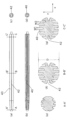
- Schematic diagrams for explaining the operation of an injection molding machine 60 used in manufacturing a liquid cosmetic feeder 4 according to one embodiment of the present invention (a) schematic diagram of the injection molding machine 60, (b) schematic diagram of a demolding process (the axis O of the liquid cosmetic feeder 4 is disposed in a direction perpendicular to the x-axis and y-axis), (c) schematic diagram of a demolding process according to another embodiment of the present invention (the axis O of the liquid cosmetic feeder 4 is disposed in the y-axis direction), (d) enlarged view of part A, (e) enlarged view of part B.
- 4A and 4B are cross-sectional views of a mold 62 corresponding to the liquid cosmetic feeder 4 of Fig. 3.
- FIG. 4 is a cross-sectional view showing a modified example of the liquid cosmetic feeder 4 of the present invention.
- FIG. 2 is a cross-sectional view of a conventional liquid cosmetic feeder 4.
- the liquid cosmetic applicator 1 is rod-shaped, supplies liquid cosmetic P from the rear end side to the front end side, and expels the liquid cosmetic P from the front end side.
- the liquid cosmetic applicator 1 comprises an applicator 2 that ejects liquid cosmetic P, a liquid cosmetic tank 3 that forms a liquid cosmetic storage space 30a that stores the liquid cosmetic P, a liquid cosmetic feeder 4 that supplies paint from the liquid cosmetic tank 3 to the applicator 2, a pressure fluctuation buffer member 5 that buffers pressure fluctuations in the liquid cosmetic storage space 30a, and an outer case 6 that is provided on the outer periphery of the pressure fluctuation buffer member 5.
- the liquid cosmetic feeder 4 is used in a liquid cosmetic applicator.
- the liquid cosmetic feeder supplies the liquid cosmetic P to the application part 2, that is, the liquid cosmetic feeder 4 is a wick provided to "relay" the liquid cosmetic P to the application part 2.
- An example of the liquid cosmetic feeder 4 of the embodiment of the present invention is shown in FIG. 3.
- the liquid cosmetic feeder 4 has, for example, a round rod shape. The rear end part of the liquid cosmetic feeder 4 is immersed in the liquid cosmetic P, and the liquid cosmetic P is sucked up to the tip side by the capillary force of the liquid cosmetic feeder 4.
- the tip part of the liquid cosmetic feeder 4 is covered by the application part 2, and is configured so that the liquid cosmetic P sucked up by the capillary force can be supplied to the application part 2 from the inside of the rear end part of the application part 2.
- the shape of the liquid cosmetic feeder 4 may be such that the tip portion is tapered as shown in Fig. 8(c) or that a step is formed at the tip portion as shown in Fig. 8(e).
- the tip portion and rear end portion may not be tapered or have a step 44, but may be cut off as shown in Fig. 8(a).
- the direction perpendicular to the axial direction i.e., the radial direction of the liquid cosmetic feeder 4
- the circumferential direction of the liquid cosmetic feeder 4 is referred to as the feeder circumferential direction.
- the vertical direction is, for example, the up-down direction in Figures 3 and 5 (y-axis direction).
- the horizontal direction is, for example, the left-right direction in Figures 3 and 5 (x-axis direction).
- the z-axis direction refers to the axis perpendicular to the x-axis and y-axis in a Cartesian coordinate system, with the x-axis being the horizontal direction, the y-axis being the vertical direction, and the z-axis being the depth direction.
- the liquid cosmetic feeder 4 is inserted into the hole 2a from the rear end side of the applicator part 2 and provided to the liquid cosmetic applicator 1.
- the liquid cosmetic feeder 4 is inserted into the applicator part 2 and used with the liquid cosmetic applicator 1.
- the hole 2a is not necessarily required.
- a cone-shaped tip space S1 is formed between the liquid cosmetic feeder 4 and the inner surface of the hole 2a.
- the rear end of the liquid cosmetic feeder 4 is disposed within the liquid cosmetic storage space 30a of the liquid cosmetic tank 3, which will be described later (see FIG. 1).
- the liquid cosmetic feeder 4 is made of a synthetic resin material, such as polyacetal (POM), polyamide (PA) (nylon), polyethylene terephthalate (PET), polybutylene terephthalate (PBT), polyethylene (PE), polypropylene (PP), polyvinyl chloride (PVC), polystyrene (PS), polycarbonate (PC), etc.
- POM polyacetal
- PA polyamide
- PET polyethylene terephthalate
- PBT polybutylene terephthalate
- PE polyethylene
- PP polypropylene
- PVC polyvinyl chloride
- PS polystyrene
- PC polycarbonate
- the present inventors have succeeded for the first time in producing a liquid cosmetic feeder 4 by injection molding. It has been thought that it is impossible to manufacture a rod-shaped liquid cosmetic feeder 4 having extremely fine liquid cosmetic flow grooves 40 with a groove width dimension W1 of approximately 0.1 mm in both the radial and axial directions as shown in Figure 10 using conventional injection molding methods.
- the inventors have devised a shape and structure of a mold 62, which will be described in detail below, and by employing injection molding, have succeeded in producing a rod-shaped liquid cosmetic feeder 4 in which extremely fine liquid cosmetic flow grooves 40 with a groove width dimension W1 of approximately 0.1 mm are formed in both the radial and axial directions.
- the plastic liquid cosmetic feeder 4 is a liquid cosmetic feeder 4 in which extremely fine liquid cosmetic flow grooves 40 with a groove width dimension W1 of 0.1 mm are formed on the outer periphery of the liquid cosmetic feeder 4 (FIG. 3).
- the liquid cosmetic feeder 4 by injection molding.
- conventional extrusion molding the workpiece is extruded from a relatively large mold 62, and a thin shape is constructed by stretching it. This made it possible to form a groove shape of about 0.1 mm on the outer circumferential surface 43 of the liquid cosmetic feeder.
- there was a great deal of variation in the outer diameter of the liquid cosmetic feeder 4 (variation of about ⁇ 0.1 mm).
- the structure within the mold 62 could be represented by laminating thin plates of 0.1 mm, 0.2 mm, etc., and therefore, the thin tube body which constitutes the liquid cosmetic feeder 4 of the liquid cosmetic applicator 1 could be successfully manufactured by injection molding.
- the liquid cosmetic feeder 4 could be integrally molded by using an injection molding method described in detail below, so that the liquid cosmetic flow groove 40 of the intended liquid cosmetic feeder 4 had a comb-like shape.
- the liquid cosmetic that can be used with the liquid cosmetic applicator 1 of the present invention is a type of cosmetic product that is in a liquid form. Examples include liquid cosmetics used in eyeliners, etc. Liquid cosmetics include facial cleansers, lotions, milky lotions, and beauty serums.
- the liquid cosmetic applicator 1 of the present invention can contain pigments and dyes, including brightness agents, that can flow through the extremely fine liquid cosmetic flow grooves, which have a groove width dimension W1 of 0.05 mm or more and 0.2 mm or less.
- the liquid cosmetic flow groove 40 is an extremely thin groove formed in the radial and axial directions on the outer periphery of the liquid cosmetic feeder 4 (see Figs. 2, 3, 4, and 5).
- the groove width dimension W1 of the liquid cosmetic flow groove 40 is extremely thin, preferably 0.05 mm or more and 0.2 mm or less.
- the liquid cosmetic flow groove 40 flows into the application unit 2 at the front of the liquid cosmetic feeder 4, and flows into the liquid cosmetic tank 3 at the rear.
- the liquid cosmetic flow groove 40 supplies the liquid cosmetic P from the liquid cosmetic tank 3 to the application unit 2 mainly by capillary action.
- the cross-sectional shape of the liquid cosmetic flow groove 40 is preferably a substantially rectangular shape recessed in the vertical direction, and is preferably formed to extend linearly in the axial direction while maintaining the comb-tooth shape.
- the liquid cosmetic flow groove 40 is recessed from the liquid cosmetic feeder outer peripheral surface 43 toward the inside in the feeder radial direction, and is formed in the axial direction of the liquid cosmetic feeder 4.
- Each liquid cosmetic flow groove 40 communicates with the brush portion at the front of the liquid cosmetic feeder 4 and communicates with the liquid cosmetic tank 3 at the rear. (Shape of Liquid Cosmetic Flow Groove 40) As shown in Figures 3 and 5, the liquid cosmetic feeder 4 is formed with a liquid cosmetic flow groove 40.
- each liquid cosmetic flow groove 40 is formed as a substantially rectangular shape concave in the vertical direction. However, it does not necessarily have to be a strict rectangle, and a slight curve may be formed.
- each liquid cosmetic flow groove 40 may be tapered.
- Each circumferential groove is formed in a comb-tooth shape on the circumferential surface of the liquid cosmetic feeder.
- the axial length of the liquid cosmetic flow groove 40 is preferably formed so that it extends linearly in the axial direction while maintaining the comb-tooth shape in cross section. However, it does not necessarily have to extend linearly in the axial direction, and it may extend in a curved or jagged shape.
- the liquid cosmetic flow groove 40 flows into the applicator part 2 at the front of the liquid cosmetic feeder 4, and flows into the liquid cosmetic tank 3 at the rear.
- each liquid cosmetic flow groove 40 of the feeder is formed to a constant width in the up-down direction (vertical direction) in FIG. 3 in order to facilitate release from the mold or slide core 65.
- the reason why the liquid cosmetic flow grooves 40 are formed in parallel in a comb-tooth shape is due to the molding method described later. In other words, it is due to the core shape of the slide core 65 or mold 62 used in the injection molding method described in detail below.
- the bottom of the liquid cosmetic flow groove 40 may be formed in various shapes such as a U-shape (FIG. 9(g)).
- Each liquid cosmetic flow groove 40 is formed to extend in the axial direction of the liquid cosmetic feeder 4.
- Each liquid cosmetic flow groove 40 is recessed from the outer peripheral surface 43 of the liquid cosmetic feeder toward the inside in the feeder radial direction, and is formed in the axial direction of the liquid cosmetic feeder 4.
- Each liquid cosmetic flow groove 40 opens into the applicator 2 at the front of the liquid cosmetic feeder 4, and opens into the liquid cosmetic tank 3 at the rear of the liquid cosmetic feeder 4.
- the liquid cosmetic flow groove 40 faces the inner peripheral surface of the hole 2a in the applicator 2, and communicates between the hole 2a of the applicator 2 and the liquid cosmetic storage space 30a of the liquid cosmetic tank 3 (see FIG. 1).
- the liquid cosmetic flow groove 40 is an extremely thin groove formed on the circumference of the liquid cosmetic feeder 4 (FIG. 3).
- the term "extremely thin” refers to, for example, in FIG. 3, the horizontal groove width dimension W1 of each liquid cosmetic flow groove 40 (left-right direction in FIG. 5) being preferably 0.05 mm or more and 0.2 mm or less.
- the groove width dimension W1 is more preferably 0.05 mm or more and 0.16 mm or less.
- the ratio of the groove width dimension W1 of the liquid cosmetic flow groove 40 to the outer diameter dimension D of the liquid cosmetic feeder 4 may be, for example, 2.5% or more and 9.2% or less, preferably 2.5% or more and 8.2% or less.
- the depth dimension L1 of the liquid cosmetic flow groove 40 in the vertical direction (left-right direction in FIG. 5) to the outer diameter dimension D (depth dimension of the liquid cosmetic flow groove 40) is preferably, for example, 25% or more and 40% or less.
- the ratio of the area occupied by the liquid cosmetic flow groove 40 is, for example, 5% or more, more preferably 10% or more, and even more preferably 20% or more.
- a plurality of liquid cosmetic flow grooves 40 are formed at intervals in the horizontal direction (y direction) as shown in Fig. 3.
- eight or ten liquid cosmetic flow grooves 40 are formed, but the number of liquid cosmetic flow grooves 40 is not limited and can be increased or decreased as appropriate.
- the liquid cosmetic flow grooves 40 are formed in a comb-like shape parallel to each other.
- the liquid cosmetic flow grooves 40 are preferably arranged in parallel to each other. This is different from the conventional liquid cosmetic feeders 4 in which the liquid cosmetic flow grooves 40 are formed radially toward the center point of the axis (see FIG. 10).
- the outer circumferential surface of the liquid cosmetic flow groove 40 may further be provided with a lateral groove (not shown) that connects adjacent liquid cosmetic flow grooves in the circumferential direction of the feeder.
- a lateral groove extends in the circumferential direction of the feeder, intersecting the liquid cosmetic flow groove 40.
- Modifications of the liquid cosmetic flow grooves 40 are shown in FIG. 9.
- the number of liquid cosmetic flow grooves 40 may be increased or decreased.
- the groove width dimension W1 of the liquid cosmetic flow grooves 40 may be narrowed.
- the groove width dimension W1 of each liquid cosmetic flow groove 40 may be a mixture of wide and narrow.
- each liquid cosmetic flow groove 40 may be tapered.
- the depth of each liquid cosmetic flow groove 40 may be changed.
- the bottom shape of each liquid cosmetic flow groove 40 may be rounded.
- the outer shape of each liquid cosmetic feeder may be as shown in the figure.
- the number of slide cores 65 may be increased or decreased as shown in the figure.
- a flow groove may be formed inside the liquid cosmetic feeder.
- the size of the mold rib receiving portion 42 may be changed.
- the mold rib receiving portion 42 is formed as a concave groove in the axial direction on the outer peripheral surface 43 of the liquid cosmetic feeder 4.
- the shape of the mold rib receiving portion 42 is not limited as long as the liquid cosmetic feeder 4, which is a molded product, can be caught by the mold rib 623 in the demolding process.
- the mold rib receiving portion 42 is shaped to fit the shape of the mold rib 623.
- the shape of the mold rib receiving portion 42 is not limited to the above shape as long as the liquid cosmetic feeder 4, which is a molded product, can be caught by the mold rib 623 in the demolding process.
- the mold rib receiving portion 42 is formed, when the slide core 65 is opened during injection molding, the mold rib receiving portion 42 of the liquid cosmetic feeder 4, which is the molded product, comes into contact with the mold rib 623 of the mold 62, enabling it to be released from the mold 62.
- the mold rib receiving portion 42 may be formed in the same shape (groove width, groove depth, and radial length of the groove) as the liquid cosmetic material flow groove 40. In this case, the mold rib receiving portion 42 can also function as the liquid cosmetic material flow groove 40.
- the present inventors have succeeded in forming the liquid cosmetic flow groove 40 by injection molding of a liquid cosmetic feeder, making it possible for the first time to form a liquid cosmetic feeder 4 by injection molding.
- the manufacturing method for the liquid cosmetic feeder 4 involves molding a synthetic resin material into a predetermined shape and size using an injection molding machine 60.
- the shape of the liquid cosmetic feeder can be completed within the injection molding process, so there is no need for cutting processes such as front and rear end processing, or cutting to extend the entire length. Cutting processes such as front and rear end processing, and cutting to extend the entire length are not necessary with the injection molding method of the present invention.
- the shape of the liquid cosmetic feeder 4 can be formed and completed entirely by the shape of the mold.
- the injection molding method for the liquid cosmetic feeder 4 of this embodiment will be described in detail below.
- the liquid cosmetic feeder 4 of this embodiment is manufactured by injection molding.
- the injection molding method of this embodiment is a technique in which synthetic resin 61, a plastic material, melted at high temperature is injected into an injection mold 62, cooled, and molded under high pressure. (Injection molding process) The procedure for the injection molding method is described below.
- the material is temporarily stored in a hopper, and then supplied to the injection unit little by little, and then sent to the heating portion of the injection unit by the drive device 64.
- the mold 62 is made up of two parts. One mold 62 is fitted to the other mold 62 and clamped. In the injection molding of this embodiment, the mold 62 may be provided with a slide core 65. 3. Injection The molten material is injected into the mold 62. 4. Pressure maintenance: The mold 62 is maintained at a pressure that makes it easy for the injected material to harden. 5. Cool and solidify. 6. Open the mold. After cooling and checking that it has solidified sufficiently, open the movable side of the mold. 7. Removal of the product The molded product is removed. Since one side of the mold 62 is fixed, the molded product is pushed out by the ejector pin 67 and removed.
- the liquid cosmetic feeder 4 of this embodiment can be manufactured, for example, by an injection molding machine 60 as shown in Fig. 6(a) .
- the injection molding machine 60 that can be used in this embodiment includes three sections: a drive device 64 that feeds the material, a nozzle 68 that heats the material with a heater 66 to make it injectable, and a mold clamping unit 63 for molding with a mold 62.
- the injection mold 62 is a metal mold into which synthetic resin is injected to form a synthetic resin material 61 into a specific shape. Basically, it is made up of two molds 62, which are opened and closed by a mold clamping unit 63.
- FIG. 7(a) is a cross-sectional view of a mold having a slide core 65
- FIG. 7(b) is a cross-sectional view of a mold having no slide core.
- the structure of the slide core 65 can be produced by bonding together a first plate-like member 651 having a thickness of 0.1 mm and a second plate-like member 652 having a thickness of 0.2 mm. There are various methods for joining the first plate-like member 651 and the second plate-like member 652, but for example, the following method can be used.
- Method using adhesive This is a method of bonding metal plates using a metal adhesive. Depending on the type of adhesive, it is possible to create a bond with high strength and excellent durability.
- Welding method This is a method of welding metal plates.
- welding There are various types of welding, such as arc welding, gas welding, and laser welding, and in the case of ultra-thin metal plates, laser welding may be the best option.
- the plate-like parts having a thickness of 0.1 mm and 0.2 mm are assembled into the slide core 65. As a result, a comb-tooth-shaped core is formed in the slide core 65.
- the method of releasing the liquid cosmetic feeder 4 from the mold 62 after injection is as follows: the upper and lower slide cores 65 are released from the restraint of the angular pins 624 and move up and down. At this point, the liquid cosmetic feeder 4, which is the injection molded product, is held by the mold ribs 623 and adheres to the upper and lower slide cores 65 and does not follow them. The injection molded liquid cosmetic feeder 4 is then pushed out by the operation of the ejector pins 67 and is completely released from the mold. First plate-like members 651 and second plate-like members 652 are alternately arranged and fixed to the slide core 65 of the mold 62.
- the first plate-like members 651 having a thickness of 0.1 mm and the second plate-like members 652 having a thickness of 0.2 mm are alternately assembled into the slide core 65 of the mold 62.
- the molded product is removed from the mold 62 by opening the slide core 65 up and down.
- the mold 62 opens left and right and the slide core 65 opens up and down simultaneously.
- the mold 62 may be opened left and right first, and then the slide core 65 may be opened up and down sequentially.
- the liquid cosmetic feeder 4 is injection molded with its axis oriented vertically (z-axis direction) relative to the plane of the drawing as shown in Fig. 6(b), but it may also be injection molded with its axis oriented horizontally (x-axis direction) as shown in Fig. 6(c).
- the above-mentioned mold 62 with a slide core has a complicated structure, and the mold 62 of the present invention does not necessarily have to include the slide core 65.
- the use of the following mold 62 is also within the scope of the present invention. That is, by forming the first plate-like member 651 and the second plate-like member 652 in a comb-like shape in the horizontal direction in the mold 62, injection molding is possible without requiring the slide core 65 (FIG. 7(b)).
- the method for releasing the liquid cosmetic feeder 4 from the mold 62 after injection is as follows, as shown in Fig.
- the left and right molds 62 are opened to the left and right by a mold opening and closing device (not shown). At this point, the liquid cosmetic feeder 4 is released from the right mold 62. Then, while being held by the mold ribs 623, the liquid cosmetic feeder 4, which is an injection-molded product, is pushed out by the operation of the ejector pins 67 and completely released from the mold.
- mold ribs 623 are formed near the center of the left and right molds 62, respectively (FIG. 6(d)).
- the shape of the mold ribs 623 is not particularly limited as long as it can easily remove the molded product from the slide core 65.
- it may be a shape that can be fitted into a recess somewhere in the molded product.
- the mold ribs 623 may be formed on either one of the left and right molds 62. The present inventors have succeeded in easily removing the molded product from the mold 62 by providing such a convex shape to the mold 62.
- the molded product can be completely removed from the mold 62 by pushing up the molded product with the ejector pin 67 .
- the slide core 65 is opened vertically, the molded product remains on one of the slide cores 65 because the plate parts of the die 62 and the molded product are in close contact with each other, making it impossible to release the molded product from the die 62 .
- a mold release rib is formed in the mold 62 (FIG. 6c).
- the mold rib 623 is formed in the center of both sides of the mold 62, but the mold rib 623 may be formed at a position shifted from the center as long as the mold release rib has a shape that can temporarily hold the liquid cosmetic feeder 4 in the mold 62.
- the mold rib 623 may be formed on either the male or female mold.
- the liquid cosmetic feeder 4 of this embodiment can be attached to various liquid cosmetic applicators 1. Below, we will explain each part of the liquid cosmetic applicator 1 to which the liquid cosmetic feeder 4 of this embodiment is attached. In the following example, an eyeliner will be explained as an example of the liquid cosmetic applicator 1.
- the liquid cosmetic feeder 4 of the present invention is a core provided to "relay" the liquid cosmetic P to the applicator part 2, and can be applied to any liquid cosmetic applicator 1 as long as it is rod-shaped, the rear end portion of which is immersed in the liquid cosmetic P, and the front end portion of which can be connected to the applicator part 2.
- the liquid cosmetic feeder 4 of this embodiment can be attached to eyeliner, eyebrow pencil, shadow liner, concealer, etc.
- the applicator 2 is, for example, a brush, which is a fibrous aggregate made of synthetic resin such as nylon or PBT (polybutylene terephthalate).
- the applicator 2 is not limited to a brush, and may be, for example, a sintered pen type or one made of porous urethane.
- the applicator 2 is a brush.
- the applicator 2 is a bundle of synthetic fibers such as nylon that have flexibility, elasticity, and flexibility.
- the applicator 2 is in the form of a round bar extending in the axial direction (longitudinal direction) around the axis O.
- the applicator 2 is also in the form of a cone whose outer diameter gradually decreases from the midpoint in the axial direction toward the front end.
- a hole 2a is formed in the rear end face of the applicator 2, which is recessed toward the front end.
- the hole 2a is in a tapered shape whose inner diameter gradually decreases from the rear end toward the front end.
- the inner diameter of the hole 2a may be equal to the outer diameter of the liquid cosmetic feeder 4 described later, or may be slightly larger than the outer diameter of the liquid cosmetic feeder 4.
- a space (clearance) through which the liquid cosmetic P can flow may be formed between the outer peripheral surface of the liquid cosmetic feeder 4 and the inner peripheral surface of the hole 2a.
- an adhesive layer 20 that bundles the fibers of the application part 2 is provided at the end on the rear end side of the application part 2.
- the above-mentioned hole 2a penetrates the adhesive layer 20.
- the adhesive layer 20 is formed by, for example, adhering the fibers of the application part 2 to each other with an adhesive or the like.
- the adhesive layer 20 is disk-shaped with the axis O as its center.
- the outer diameter of the adhesive layer 20 is slightly larger than the outer diameter of the application part 2, so that the adhesive layer 20 protrudes from the application part 2 to the outer periphery in a flange-like shape.
- the liquid cosmetic tank 3 is provided extending from the end portion on the rear end side of the liquid cosmetic feeder 4 toward the rear end side.
- the liquid cosmetic tank 3 has an outer tube 30 having a cylindrical shape extending in the axial direction, and a tail plug 39 that closes the rear end side of the outer tube 30.
- the space surrounded by the outer tube 30, the tail plug 39, and a pressure fluctuation buffer member 5 described below forms a liquid cosmetic storage space 30a that stores paint.
- the liquid cosmetic storage space 30a stores liquid cosmetic P, which may be liquid paint or liquid paint containing solids.
- the liquid paint is, for example, a liquid cosmetic used for eyeliner.
- the solid matter has a higher specific gravity than the liquid paint, and examples of such solid matter include metal powders such as titanium and aluminum, glitter made by vapor deposition of gold, silver, aluminum, tin, etc., and inorganic substances such as glass beads.
- the viscosity of the liquid cosmetic P containing the solid matter is preferably, for example, about 30 mPa ⁇ s or less.
- a stirring member M is housed in the liquid cosmetic storage space 30a in the liquid cosmetic tank 3.
- the liquid cosmetic P in the liquid cosmetic tank 3 can be stirred by the stirring member M by rocking the entire liquid cosmetic applicator 1 in the axial direction.
- the shape of the stirring member M is not limited, but may be, for example, a sphere, a cylinder, or a polyhedron such as a cube or a rectangular parallelepiped. Depending on the type of liquid cosmetic P, the stirring member M may not necessarily be provided.
- the outer cylinder portion 30 has a liquid cosmetic storage space 30a and a feeder storage area 30b extending from the liquid cosmetic storage space 30a toward the front end.
- the feeder storage area 30b is disposed radially outward of the liquid cosmetic feeder 4 and overlaps the liquid cosmetic feeder 4 as viewed from the feeder radial direction, covering the liquid cosmetic feeder 4.
- the feeder storage area 30b has a tapered shape in which the outer diameter gradually decreases from a midpoint in the axial direction toward the front end. As shown in FIG. 2, the front end of the feeder storage area 30b is disposed radially outward of the applicator 2 and overlaps the applicator 2 as viewed from the feeder radial direction, covering the applicator 2.
- an outer tube first step surface 31 that forms an annular shape centered on the axis O facing the rear end side in the axial direction and an outer tube second step surface 32 that is arranged on the rear end side of the outer tube first step surface 31 and forms an annular shape centered on the axis O are formed at an interval in the axial direction.
- an outer tube first recess 33 that is recessed in an annular shape centered on the axis O from the inner peripheral surface of the outer tube portion 30 to the outside in the feeder radial direction and an outer tube second recess 34 are formed.
- an air circulation groove 30x that communicates with the outer tube first recess 33, extends in the axial direction, and opens on the end face on the front end side of the outer tube portion 30 is formed in a part of the feeder circumferential direction. Air is exchanged inside and outside the buffer space K described below through the air flow groove 30x, the outer cylinder first recess 33, and the outer cylinder second recess 34.
- the feeder housing area 30b in the outer cylinder portion 30 is provided with an outer cylinder flange 35 that protrudes annularly outward in the feeder radial direction at a mid-way axial position that is rearward of the outer cylinder second step surface 32 (see FIG. 2).
- an inner cylinder 36 is provided between the outer cylinder 30 and the application part 2.
- the inner cylinder 36 extends in the axial direction and engages with the fixing layer 20 and the outer cylinder 30.
- the inner cylinder 36 covers the end of the application part 2 on the rear end side so as to press it from the outside in the feeder radial direction.
- an inner cylinder outer step surface 36a is formed on the outer peripheral surface of the inner cylinder 36, which is an annular shape centered on the axis O facing the front end side in the axial direction.
- the inner cylinder outer step surface 36a forms an outer protrusion 37 on the outer peripheral surface of the inner cylinder 36, which is an annular shape centered on the axis O protruding outward in the feeder radial direction. Therefore, the outer diameter of the inner cylinder 36 is larger on the rear end side than on the front end side.
- the outer convex portion 37 of the inner tube portion 36 is disposed within the outer tube first recess 33 of the outer tube portion 30, and the inner tube portion 36 is disposed so that the inner tube outer step surface 36a of the inner tube portion 36 faces the outer tube first step surface 31 of the outer tube portion 30 in the axial direction.
- the inner tube outer step surface 36a of the inner tube portion 36 engages with the outer tube first step surface 31 of the outer tube portion 30, and the inner tube portion 36 engages with the outer tube portion 30.
- the inner tube inner step surface 36b is formed on the inner peripheral surface of the inner tube portion 36, which is disposed rearward of the inner tube outer step surface 36a and forms a ring shape centered on the axis O facing the rear end side.
- This inner tube inner step surface 36b forms an inner recess 38 on the inner peripheral surface of the inner tube portion 36, which forms a ring shape centered on the axis O that is recessed outward in the feeder radial direction.
- An adhesive layer 20 is disposed within the inner recess 38, and the inner cylinder portion 36 and the adhesive layer 20 engage with each other, and the outer cylinder portion 30 supports the application portion 2 via the inner cylinder portion 36.
- the outer case 6 abuts against the outer tube flange 35 of the outer tube portion 30 from the rear end side in the axial direction, and covers the outer tube portion 30 from the outside in the feeder radial direction on the rear end side of the outer tube flange 35.
- the outer case 6 is a bottomed cylindrical shape extending in the axial direction about the axis O so that the outer tube portion 30 can be inserted.
- the outer tube portion 30 is fitted into the outer case 6, and the outer case 6 and the outer tube portion 30 are fixed together.
- a rear end space S2 is formed inside the outer case 6 in a region sandwiched between the bottom surface of the outer case 6 and the tail plug 39 of the liquid cosmetic tank 3 (see FIG. 1).
- the pressure fluctuation buffering member 5 has a feeder holding tube 50 and a buffering mechanism 51 that forms a buffer space K between the feeder holding tube 50 and the inner peripheral surface of the outer tube portion 30 on the outer side of the feeder radial direction of the feeder than the feeder holding tube 50.
- the pressure fluctuation buffering member 5 is made of synthetic resin.
- the liquid cosmetic P in the liquid cosmetic tank 3 is a water-based paint
- ABS resin, AS resin, PET resin, PBT resin, styrene resin, POM resin, polycarbonate, polyamide, modified polyphenylene ether, etc. can be used as the synthetic resin.
- the liquid cosmetic P in the liquid cosmetic tank 3 is an oil-based paint (particularly a paint with alcohol as the main solvent), PE resin, PP resin, POM resin, PET resin, PBT resin, polyamide, etc. can be used as the synthetic resin.
- the feeder holding tube 50 extends in the axial direction and has a cylindrical main body tube portion 52 centered on the axis O and through which the liquid cosmetic feeder 4 is inserted, and an extension portion 53 provided integrally with the main body tube portion 52 on the rear end side of the main body tube portion 52.
- the liquid cosmetic feeder 4 is fitted into the main body tube portion 52, so that the liquid cosmetic flow groove 40 of the liquid cosmetic feeder 4 faces the inner peripheral surface of the main body tube portion 52 in the feeder radial direction.
- the liquid cosmetic feeder outer peripheral surface 43 (see FIG. 3) of the liquid cosmetic feeder 4 is in contact with the inner peripheral surface of the main body tube portion 52.
- the groove distance W2 (see FIG. 3) of the liquid cosmetic feeder outer peripheral surface 43 in the feeder horizontal direction is very small, and the liquid cosmetic feeder 4 is fitted into the main body tube portion 52, so that a very small gap (not shown) is formed between the main body tube portion 52 and the liquid cosmetic feeder 4. Due to this small gap, a space exists between the main body tube portion 52 and the liquid cosmetic feeder 4 in which horizontally adjacent liquid cosmetic flow grooves 40 communicate with each other.
- a connecting flow path F that communicates with the liquid cosmetic flow groove 40 is formed in the main body tube portion 52 of the pressure fluctuation buffering member 5.
- the formation of the liquid cosmetic flow groove 40 causes a larger amount of liquid cosmetic P to exist between the pressure fluctuation buffering member 5 and the liquid cosmetic feeder 4, but the connecting flow path F improves the entry of the liquid cosmetic P into the buffer space K, thereby preventing leakage of the liquid cosmetic P.
- the provision of the connecting flow path F allows air to move between the buffer space K and the liquid cosmetic storage space 30a, and the liquid cosmetic P to move between the buffer space K and the liquid cosmetic flow groove 40 by the connecting flow path F, effectively suppressing leakage of the liquid cosmetic P.
- the outer peripheral surface of the liquid cosmetic feeder 4 may further be provided with a horizontal groove (not shown) that connects adjacent liquid cosmetic flow grooves 40 in the circumferential direction of the feeder.
- a horizontal groove extends in the circumferential direction of the feeder, intersecting the liquid cosmetic flow grooves 40.
- Such a horizontal groove allows the liquid cosmetic P to be transferred between the liquid cosmetic flow grooves 40, and allows the liquid cosmetic P to flow more smoothly toward the front end.
- the buffer mechanism 51 is formed integrally with the feeder holding tube 50.
- the buffer mechanism 51 has a partition member 56 that protrudes annularly from the main body tube portion 52 toward the outside in the feeder radial direction with the axis O as the center at an axial midpoint of the main body tube portion 52, a first convex member 57 formed on the outer circumferential surface of the main body tube portion 52 on the rear end side of the partition member 56, and a second convex member 58 formed on the outer circumferential surface of the main body tube portion 52 on the front end side of the partition member 56.
- Example 1 The liquid cosmetic feeder 4 was manufactured by injection molding, and the liquid cosmetic feeder 4 was used to manufacture an eyeliner. In this Example 1, no cutting processes such as front end processing and rear end processing, which are post-processes, were carried out.
- the mold 62 for forming the liquid cosmetic feeder 4 was produced by bonding together thin plates having a thickness of, for example, 0.1 mm or 0.2 mm (FIG. 6(c)).
- the mold 62 is formed with a comb-like shape corresponding to the liquid cosmetic flow groove 40 of the liquid cosmetic feeder 4, which has a groove width dimension W1 of 0.1 mm. Then, using an injection molding machine 60 (FIG. 6) equipped with this mold 62, the liquid cosmetic feeder 4 of the liquid cosmetic applicator 1 was successfully produced by injection molding.
- the liquid cosmetic feeder 4 produced by the injection molding method was assembled into a feeder holding cylinder 50 to produce a liquid cosmetic applicator 1 (eyeliner) (FIG. 4).
- the liquid cosmetic feeder 4 is fixed to the feeder holding cylinder 50 by press-fitting.
- the variation in the outer diameter dimension D of the liquid cosmetic applicator 1 could be suppressed to within ⁇ 0.02 mm, and the assembly defect rate was reduced.
- the assembly defect rate of the liquid cosmetic applicator 1 produced by the injection molding method was 0 out of 100 (defective rate 0%). Considering that the defective rate was 35% in the case of Comparative Example 1 described below, it was confirmed that the injection molding method and liquid cosmetic feeder 4 of the present invention enable the production of a liquid cosmetic feeder 4 with excellent stable dimensions.
- Example 2 As Example 2, the eyeliner shown in FIG. 5 was produced. The difference from Example 1 is that the liquid cosmetic feeder 4 is fixed to the main body tube portion 52 by providing a step to prevent it from falling off (it is not press-fitted). As a result, the matching with the prescription, prevention of the brush tip cracking, assembly method, etc. are different from those of the eyeliner of Example 1.
- Injection molded outer capillary thin tube (outer diameter ⁇ 1.9, groove width 0.13 mm, 12 grooves, 2 of which serve both as grooves for receiving mold ribs and as grooves for flowing liquid cosmetics)
- the liquid cosmetic feeder 4 of the present invention smoothly guides the liquid cosmetic P so that it can be discharged.
Landscapes
- Moulds For Moulding Plastics Or The Like (AREA)
Abstract
Priority Applications (1)
| Application Number | Priority Date | Filing Date | Title |
|---|---|---|---|
| PCT/JP2023/030065 WO2025041243A1 (fr) | 2023-08-21 | 2023-08-21 | Dispositif d'alimentation de produit cosmétique liquide et applicateur de produit cosmétique liquide |
Applications Claiming Priority (1)
| Application Number | Priority Date | Filing Date | Title |
|---|---|---|---|
| PCT/JP2023/030065 WO2025041243A1 (fr) | 2023-08-21 | 2023-08-21 | Dispositif d'alimentation de produit cosmétique liquide et applicateur de produit cosmétique liquide |
Publications (1)
| Publication Number | Publication Date |
|---|---|
| WO2025041243A1 true WO2025041243A1 (fr) | 2025-02-27 |
Family
ID=94731822
Family Applications (1)
| Application Number | Title | Priority Date | Filing Date |
|---|---|---|---|
| PCT/JP2023/030065 Pending WO2025041243A1 (fr) | 2023-08-21 | 2023-08-21 | Dispositif d'alimentation de produit cosmétique liquide et applicateur de produit cosmétique liquide |
Country Status (1)
| Country | Link |
|---|---|
| WO (1) | WO2025041243A1 (fr) |
Citations (4)
| Publication number | Priority date | Publication date | Assignee | Title |
|---|---|---|---|---|
| JPS59125314U (ja) | 1983-02-10 | 1984-08-23 | 株式会社資生堂 | 液状化粧料容器 |
| JP2001347787A (ja) * | 2000-06-08 | 2001-12-18 | Mitsubishi Pencil Co Ltd | 塗布液保溜体 |
| JP2015024584A (ja) | 2013-07-26 | 2015-02-05 | 三菱鉛筆株式会社 | 液体塗布具 |
| JP2019193698A (ja) | 2018-05-01 | 2019-11-07 | ぺんてる株式会社 | 液状化粧料用塗布具 |
-
2023
- 2023-08-21 WO PCT/JP2023/030065 patent/WO2025041243A1/fr active Pending
Patent Citations (4)
| Publication number | Priority date | Publication date | Assignee | Title |
|---|---|---|---|---|
| JPS59125314U (ja) | 1983-02-10 | 1984-08-23 | 株式会社資生堂 | 液状化粧料容器 |
| JP2001347787A (ja) * | 2000-06-08 | 2001-12-18 | Mitsubishi Pencil Co Ltd | 塗布液保溜体 |
| JP2015024584A (ja) | 2013-07-26 | 2015-02-05 | 三菱鉛筆株式会社 | 液体塗布具 |
| JP2019193698A (ja) | 2018-05-01 | 2019-11-07 | ぺんてる株式会社 | 液状化粧料用塗布具 |
Similar Documents
| Publication | Publication Date | Title |
|---|---|---|
| JP7300466B2 (ja) | 中継芯、筆先ユニット及び液体塗布具 | |
| US20060017314A1 (en) | Manufacturing method for multi-color extruded acrylic cosmetic brushes and brush handles | |
| US11845210B2 (en) | Injection molding apparatus and cap member | |
| CN101318372A (zh) | 一种注塑机注塑螺杆 | |
| JP6780338B2 (ja) | ピペットチップとそのピペットチップに装着されるノズルとの連結構造 | |
| WO2025041243A1 (fr) | Dispositif d'alimentation de produit cosmétique liquide et applicateur de produit cosmétique liquide | |
| JP5805992B2 (ja) | 発泡成形用射出成形機の射出装置 | |
| US7399178B2 (en) | Injection device having a reciprocal plunger | |
| KR20260057034A (ko) | 액체 화장료 피더 및 액체 화장료 도포구 | |
| US11559930B2 (en) | Injection-moulded component, joint, injection-moulding device, and method for producing an injection-moulded component | |
| EP0906180A1 (fr) | Dispositif d'injection | |
| KR20020060033A (ko) | 연필형 화장품 | |
| JP5791709B2 (ja) | ノズルハウジングによって摺動支持される弁ステムを有する金型工具システム | |
| CN102802909A (zh) | 含有相对于阀针尖端定位的树脂止流装置的模具工具组件 | |
| CN114585491A (zh) | 生产大理石纹模制件的方法和装置及生产该装置的方法 | |
| JPH08156047A (ja) | 射出装置 | |
| EP2665593A1 (fr) | Appareil de pointe de buse comprenant un corps de pointe de buse ayant un élément de décharge de pression | |
| JP2023071257A (ja) | 射出成形装置 | |
| WO2023100270A1 (fr) | Eyeliner de type stylo à liquide direct | |
| US20070200279A1 (en) | Circular Resin-Molded Product Having Circular Center Hole And Method And Apparatus For Molding The Same | |
| JPH0811171A (ja) | 射出成形用金型装置 | |
| WO2024075148A1 (fr) | Eyeliner de type stylo à liquide direct | |
| US20200346381A1 (en) | Mold, ejection structure thereof and manufacturing method of fan | |
| JP2004174956A (ja) | 塗布具 | |
| CN215940452U (zh) | 一种喷射阀 |
Legal Events
| Date | Code | Title | Description |
|---|---|---|---|
| 121 | Ep: the epo has been informed by wipo that ep was designated in this application |
Ref document number: 23949704 Country of ref document: EP Kind code of ref document: A1 |
|
| DPE1 | Request for preliminary examination filed after expiration of 19th month from priority date (pct application filed from 20040101) | ||
| ENP | Entry into the national phase |
Ref document number: 2025541197 Country of ref document: JP Kind code of ref document: A |
|
| WWE | Wipo information: entry into national phase |
Ref document number: 2025541197 Country of ref document: JP |
|
| WWE | Wipo information: entry into national phase |
Ref document number: 2023949704 Country of ref document: EP |
|
| NENP | Non-entry into the national phase |
Ref country code: DE |