WO2025033120A1 - モータコア用の圧粉磁心、およびステータコア - Google Patents
モータコア用の圧粉磁心、およびステータコア Download PDFInfo
- Publication number
- WO2025033120A1 WO2025033120A1 PCT/JP2024/025544 JP2024025544W WO2025033120A1 WO 2025033120 A1 WO2025033120 A1 WO 2025033120A1 JP 2024025544 W JP2024025544 W JP 2024025544W WO 2025033120 A1 WO2025033120 A1 WO 2025033120A1
- Authority
- WO
- WIPO (PCT)
- Prior art keywords
- insulating coating
- core
- powder
- iron
- motor
- Prior art date
- Legal status (The legal status is an assumption and is not a legal conclusion. Google has not performed a legal analysis and makes no representation as to the accuracy of the status listed.)
- Pending
Links
Images



Classifications
-
- H—ELECTRICITY
- H01—ELECTRIC ELEMENTS
- H01F—MAGNETS; INDUCTANCES; TRANSFORMERS; SELECTION OF MATERIALS FOR THEIR MAGNETIC PROPERTIES
- H01F1/00—Magnets or magnetic bodies characterised by the magnetic materials therefor; Selection of materials for their magnetic properties
- H01F1/01—Magnets or magnetic bodies characterised by the magnetic materials therefor; Selection of materials for their magnetic properties of inorganic materials
- H01F1/03—Magnets or magnetic bodies characterised by the magnetic materials therefor; Selection of materials for their magnetic properties of inorganic materials characterised by their coercivity
- H01F1/12—Magnets or magnetic bodies characterised by the magnetic materials therefor; Selection of materials for their magnetic properties of inorganic materials characterised by their coercivity of soft-magnetic materials
- H01F1/14—Magnets or magnetic bodies characterised by the magnetic materials therefor; Selection of materials for their magnetic properties of inorganic materials characterised by their coercivity of soft-magnetic materials metals or alloys
- H01F1/20—Magnets or magnetic bodies characterised by the magnetic materials therefor; Selection of materials for their magnetic properties of inorganic materials characterised by their coercivity of soft-magnetic materials metals or alloys in the form of particles, e.g. powder
- H01F1/22—Magnets or magnetic bodies characterised by the magnetic materials therefor; Selection of materials for their magnetic properties of inorganic materials characterised by their coercivity of soft-magnetic materials metals or alloys in the form of particles, e.g. powder pressed, sintered, or bound together
-
- H—ELECTRICITY
- H01—ELECTRIC ELEMENTS
- H01F—MAGNETS; INDUCTANCES; TRANSFORMERS; SELECTION OF MATERIALS FOR THEIR MAGNETIC PROPERTIES
- H01F3/00—Cores, Yokes, or armatures
- H01F3/08—Cores, Yokes, or armatures made from powder
-
- H—ELECTRICITY
- H02—GENERATION; CONVERSION OR DISTRIBUTION OF ELECTRIC POWER
- H02K—DYNAMO-ELECTRIC MACHINES
- H02K1/00—Details of the magnetic circuit
- H02K1/02—Details of the magnetic circuit characterised by the magnetic material
Definitions
- the present disclosure relates to a powder magnetic core for a motor core, and a stator core.
- This application claims priority based on Japanese Patent Application No. 2023-129249 dated August 8, 2023, and incorporates all of the contents of the above-mentioned Japanese application by reference.
- Patent Document 1 discloses a powder magnetic core used in an axial gap motor.
- the powder magnetic core includes a yoke portion and a teeth portion.
- a coil is arranged on the outer periphery of the teeth portion.
- the powder magnetic core includes a compact containing iron-based soft magnetic powder, and an insulating resin coating that covers part of the surface of the compact.
- the insulating resin coating is formed by applying resin to the surface of the compact. The resin is applied by spray painting, electrocoating, or powder coating.
- the powder magnetic core for a motor core disclosed herein comprises a powder compact having a plurality of coating particles, and a first insulating coating covering the surface of the powder compact.
- Each of the plurality of coating particles has an iron-based particle and a second insulating coating covering the surface of the iron-based particle.
- the thickness of the second insulating coating is 10 nm or more and 1000 nm or less.
- the first insulating coating contains a resin and Fe.
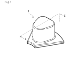
- FIG. 1 is a schematic perspective view showing an example of a powder magnetic core for a motor core according to a first embodiment.
- FIG. 2 is a cross-sectional view taken along line II-II of FIG.
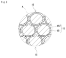
- FIG. 3 is a schematic cross-sectional view showing a region A in FIG.
- FIG. 4 is a perspective view showing an outline of a stator core according to the second embodiment.
- FIG. 5 is a schematic perspective view showing an example of a stator.
- FIG. 6 is a schematic cross-sectional view showing an example of an axial gap motor.
- One of the objectives of this disclosure is to provide a powder magnetic core for a motor core and a stator core that have excellent electrical insulation properties.
- the powder magnetic core for a motor core according to the present disclosure has excellent electrical insulation properties.
- a powder magnetic core for a motor core includes a powder compact having a plurality of coating particles, and a first insulating coating covering the surface of the powder compact.
- Each of the plurality of coating particles has an iron-based particle and a second insulating coating covering the surface of the iron-based particle.
- the thickness of the second insulating coating is 10 nm or more and 1000 nm or less.
- the first insulating coating includes a resin and Fe.
- the powder magnetic core for motor cores disclosed herein has excellent electrical insulation properties due to the first insulating coating containing resin and Fe, as shown in the test example described below.
- a second insulating coating with a thickness of 10 nm or more tends to insulate adjacent iron-based particles from each other.
- a second insulating coating with a thickness of 1000 nm or less tends to increase the relative density of the compact.
- the thickness of the first insulating coating may be 5 ⁇ m or more and 100 ⁇ m or less.
- a first insulating coating with a thickness of 5 ⁇ m or more tends to improve the electrical insulation of the powder magnetic core for the motor core. With a thickness of the first insulating coating of 100 ⁇ m or less, the powder magnetic core for the motor core is less likely to become large.
- the Fe content in the first insulating coating may be 0.5% by mass or more and 10% by mass or less.
- the powder magnetic core for motor cores described above in (3) has excellent electrical insulation properties due to the first insulating coating that contains a specific amount of Fe.
- the hardness of the first insulating coating measured by a nanoindentation method may be 200 MPa or more.
- a first insulating coating with a hardness of 200 MPa or more is likely to mechanically protect the powder compact.
- a first insulating coating with a hardness of 200 MPa or more has a relatively high cross-link density.
- a first insulating coating with a high cross-link density has excellent electrical insulation properties. In other words, a first insulating coating with a hardness of 200 MPa or more is likely to improve the electrical insulation properties of a powder magnetic core for a motor core.
- the hardness of the first insulating coating measured by a nanoindentation method may be 400 MPa or less.
- the first insulating coating which has a hardness of 400 MPa or less, is less susceptible to damage such as cracks or breakage caused by vibrations when the axial gap motor is in operation, making it easier to improve the electrical insulation of the powder magnetic core for the motor core.
- the resin may contain at least one type of resin selected from the group consisting of epoxy-based, acrylic-based, fluorine-based, and polyimide-based resins.
- the above resins are good at improving the electrical insulation of powder magnetic cores for motor cores.
- the material of the second insulating coating may be at least one selected from the group consisting of phosphate, silica, magnesium oxide, and aluminum oxide.
- the second insulating coating can reduce iron losses such as eddy current losses.
- the relative density of the powder compact may be 90% or more.
- the magnetic properties of the above-mentioned powder compact such as the saturation magnetic flux density, tend to be high.
- the powder compact may have a plurality of surfaces and corners between adjacent surfaces, and the radius of curvature of the corners may be 0.5 mm or more.
- the thickness of the first insulating coating covering the surface portion and the thickness of the first insulating coating covering the corners tend to be uniform. Corners with a radius of curvature of 0.5 mm or more are less likely to be damaged.
- the radius of curvature of the corner may be 3.0 mm or less.
- the radius of curvature of the corners is 3.0 mm or less, making it easier to increase the cross-sectional area of the compact.
- the average particle size of the iron-based particles may be 30 ⁇ m or more and 350 ⁇ m or less.
- the relative permeability of iron-based particles with an average particle size of 30 ⁇ m or more tends to be large.
- the eddy current loss of iron-based particles with an average particle size of 300 ⁇ m or less tends to be small.
- the iron-based particles are pure iron or an iron alloy, and the iron alloy may be an Fe-Si alloy or an Fe-Al alloy.
- the saturation magnetic flux density of iron-based particles made of pure iron is higher than that of iron alloys. Therefore, the saturation magnetic flux density of a powder compact having iron-based particles made of pure iron is likely to be high. In addition, iron-based particles made of pure iron have better formability than iron alloys. Therefore, the relative density of a powder compact having iron-based particles made of pure iron is likely to be high.
- the electrical resistance of iron alloys is greater than that of pure iron. Therefore, iron losses such as eddy current losses in iron-based particles made of iron alloys tend to be small. Therefore, losses in powder magnetic cores for motor cores that have iron-based particles made of iron alloys tend to be small.
- a stator core according to one embodiment of the present disclosure is a stator core for an axial gap motor, and includes a powder magnetic core for a motor core according to any one of (1) to (12) above.
- the stator core has excellent electrical insulation because it is equipped with a powder magnetic core for the motor core.
- the motor core dust core 1 according to the first embodiment includes a powder compact 10 and a first insulating coating 50.
- the powder compact 10 is composed of an aggregate of a plurality of coated particles 15.
- FIG. 3 shows an enlarged view of region A in FIG. 2.
- FIG. 2 is a cross-sectional view of the motor core dust core 1 according to the first embodiment along line II-II in FIG. 1.
- each coated particle 15 has an iron-based particle 151 and a second insulating coating 152.
- the second insulating coating 152 covers the surface of the iron-based particle 151.
- the first insulating coating 50 covers the surface of the powder compact 10 as shown in FIG. 2.
- One of the features of the motor core dust core 1 according to the first embodiment is that the first insulating coating 50 shown in FIG. 2 is composed of a specific material.
- the motor core powder core 1 of embodiment 1 shown in FIG. 1 is used to construct, for example, a stator core 7 of embodiment 2 described below with reference to FIG. 4.
- the compact 10 of the motor core powder core 1 that constructs the stator core 7 includes a yoke 30 and teeth 20 described below as shown in FIG. 2.
- the stator core 7 shown in FIG. 4 is used, for example, in a stator 8 described below with reference to FIG. 5, and an axial gap motor 9 described below with reference to FIG. 6.
- the green compact 10 shown in FIG. 2 is composed of an aggregate of a plurality of coated particles 15 as shown in FIG. 3.
- the shape of the green compact 10 can be appropriately selected.
- the green compact 10 has a plurality of surface portions 11 and corner portions 12.
- the surface portions 11 are the outer peripheral surface 31, the inner peripheral surface 32, the upper surface 33, the lower surface 34, the first side surface, and the second side surface of the yoke 30, which will be described later, and the side surface 21 and the end surface 22 of the teeth 20, which will be described later.
- the surface portions 11 are planar or curved.
- the corner portions 12 are provided between the adjacent surface portions 11.
- the corner portions 12 refer to the region between the first inflection point and the second inflection point in a cross section perpendicular to the ridge line constituting the corner portions 12.
- the first inflection point is a point where the curvature of the first surface portion 11 of the adjacent surface portions 11 changes in the cross section.
- the second inflection point is a point at which the curvature of the second surface portion 11 of the adjacent surface portions 11 changes in the cross section.
- the multiple corners 12 include corners 12 that are curved.
- the radius of curvature of the corners 12 that are curved and that are covered with the first insulating coating 50 is, for example, 0.5 mm or more.
- the thickness of the first insulating coating 50 that covers the surface portion 11 and the thickness of the first insulating coating 50 that covers the corners 12 tend to be uniform.
- the radius of curvature of the corners 12 that are curved and that are not covered with the first insulating coating 50 may be 0.5 mm or more, or may be less than 0.5 mm.
- the corners 12 that have a radius of curvature of 0.5 mm or more are less likely to be damaged.
- the radius of curvature of the corners 12 that are not covered with the first insulating coating 50 is also, for example, 0.5 mm or more.
- the radius of curvature of the corner 12 covered with the first insulating coating 50 and the radius of curvature of the corner 12 not covered with the first insulating coating 50 may be 0.8 mm or more, particularly 1.0 mm or more.
- the upper limit of the radius of curvature of the corner 12 covered with the first insulating coating 50 and the radius of curvature of the corner 12 not covered with the first insulating coating 50 is 3.0 mm in practical use. When the radius of curvature of the corner 12 is 3.0 mm or less, the cross-sectional area of the compact 10 can be easily increased.
- the radius of curvature of the corner 12 covered with the first insulating coating 50 and the radius of curvature of the corner 12 not covered with the first insulating coating 50 may be 0.5 mm or more and 3.0 mm or less, further 0.8 mm or more and 3.0 mm or less, particularly 1.0 mm or more and 3.0 mm or less.
- the corner 12 is composed of a plurality of curved surfaces with different radii of curvature, the smallest radius of curvature is set as the radius of curvature of the corner 12.
- the coated particle 15 has an iron-based particle 151 and a second insulating coating 152 .
- the iron-based particles 151 are made of a soft magnetic material.
- the soft magnetic material is pure iron or an iron alloy. Pure iron means that the purity of Fe (iron) is 99% or more. In other words, pure iron means that the Fe content is 99% or more by mass. This content is a ratio with the mass of the soft magnetic material being 100% by mass.
- the iron-based particles 151 made of pure iron have a higher saturation magnetic flux density than an iron alloy. Therefore, the saturation magnetic flux density of the powder compact 10 having the iron-based particles 151 made of pure iron is likely to be high.
- the iron-based particles 151 made of pure iron have better moldability than iron alloys. Therefore, the relative density of the powder compact 10 having the iron-based particles 151 made of pure iron is likely to be high.
- An iron alloy contains an additive element, with the remainder being Fe and unavoidable impurities.
- the iron alloy contains the most Fe.
- the iron alloy is, for example, at least one selected from the group consisting of an Fe-Si (silicon) based alloy, an Fe-Al (aluminum) based alloy, an Fe-Si-Al based alloy, and an Fe-Ni (nickel) based alloy.
- the Fe-Si based alloy is, for example, silicon steel.
- the Fe-Si-Al based alloy is, for example, sendust.
- the Fe-Ni based alloy is, for example, permalloy.
- the electrical resistance of an iron alloy is greater than that of pure iron.
- the dust core 1 for a motor core may contain both the iron-based particles 151 made of pure iron and the iron-based particles 151 made of an iron alloy.
- the average particle size of the iron-based particles 151 is, for example, 30 ⁇ m or more and 350 ⁇ m or less.
- the relative permeability of iron-based particles 151 with an average particle size of 30 ⁇ m or more tends to be large.
- the eddy current loss of iron-based particles 151 with an average particle size of 350 ⁇ m or less tends to be small.
- the average particle size of the iron-based particles 151 is furthermore 50 ⁇ m or more and 280 ⁇ m or less, particularly 70 ⁇ m or more and 260 ⁇ m or less.
- the average particle size of the iron-based particles 151 is obtained as follows.
- the cross section of the powder compact 10 is observed with a SEM (Scanning Electron Microscope).
- An observation image of the cross section is obtained.
- the magnification of the SEM is 50 times or more and 300 times or less.
- the size of the observation image is 2400 ⁇ m ⁇ 1800 ⁇ m.
- the number of observation images obtained is 50 or more.
- One observation image may be obtained for one cross section, or multiple observation images may be obtained for one cross section.
- Each of the obtained observation images is processed to extract the contours of the iron-based particles 151.
- the image processing is, for example, a binarization process.
- the area is obtained for each of all the iron-based particles 151 present in each observation image.
- the diameter of a circle having the same area as each area is obtained.
- the average value of all the obtained diameters is obtained. This average value is set as the average particle size of the iron-based particles 151.
- the second insulating coating 152 covers the iron-based particles 151.
- the second insulating coating 152 can reduce iron loss such as eddy current loss.
- the dust core 1 for motor cores having the second insulating coating 152 is easy to reduce loss.
- the material of the second insulating coating 152 is, for example, at least one selected from the group consisting of phosphate, silica, magnesium oxide, and aluminum oxide. Phosphate has excellent adhesion to the iron-based particles 151 and is also excellent in deformability.
- the second insulating coating 152 is easy to deform following the deformation of the iron-based particles 151 described above in step A of producing the compact 10 in the manufacturing method of the dust core for motor cores described later, and is difficult to damage. Therefore, such a dust core 1 for motor cores is easy to reduce loss. It is acceptable to use a material other than the above examples for the second insulating coating 152 as long as it has the effect of reducing iron loss such as eddy current loss.
- the thickness of the second insulating coating 152 is, for example, 10 nm or more and 1000 nm or less.
- the second insulating coating 152 having a thickness of 10 nm or more easily insulates adjacent iron-based particles 151 from each other.
- the relative density of the green compact 10 is easily increased by making the thickness of the second insulating coating 152 1000 nm or less.
- the thickness of the second insulating coating 152 is furthermore 30 nm or more and 700 nm or less, particularly 50 nm or more and 500 nm or less.
- the thickness of the second insulating coating 152 is obtained as follows.
- the cross section of the powder compact 10 is observed with a TEM (Transmission Electron Microscope).
- An observation image of the cross section is obtained.
- the magnification of the TEM is 100,000 times or more and 300,000 times or less.
- the size of the observation image is 2 ⁇ m ⁇ 2 ⁇ m.
- the number of observation images obtained is 10 or more.
- One observation image may be obtained per cross section, or multiple observation images may be obtained per cross section.
- the thickness of the second insulating coating 152 is measured for each of all coated particles 15 present in each observation image.
- the length of the second insulating coating 152 along the normal to the contour of the iron-based particle 151 is measured at 10 or more points per coated particle 15.
- the average value of all the above lengths is defined as the thickness of the second insulating coating 152.
- the number of measurements to obtain this thickness is 100 or more.
- the relative density of the powder compact 10 is, for example, 90% or more.
- the powder compact 10 with a relative density of 90% or more is likely to have a high saturation magnetic flux density.
- the powder compact 10 with a relative density of 90% or more is likely to have high mechanical properties such as strength.
- the powder compact 10 with a relative density of 90% or more has few voids communicating from the inside of the powder compact 10 to the outside of the powder compact 10. In some cases, there are almost no voids communicating from the inside of the powder compact 10 to the outside during the formation of the first insulating coating 50, even if the first insulating coating 50 described later is formed so as to cover the entire surface of the powder compact 10. Therefore, pinholes are unlikely to be formed in the first insulating coating 50.
- the powder compact 10 with a high relative density is likely to form a first insulating coating 50 with excellent electrical insulation.
- the relative density is further 93% or more, particularly 95% or more.
- the relative density is 99% or less. That is, the relative density is from 90% to 99%, more preferably from 93% to 99%, and particularly preferably from 95% to 99%.
- the relative density of the powder compact 10 refers to the ratio (%) of the actual density of the powder compact 10 to the true density of the powder compact 10. In other words, the relative density of the powder compact 10 is calculated by [(actual density of the powder compact 10/true density of the powder compact 10) x 100]. The actual density of the powder compact 10 can be calculated by the Archimedes method. The true density of the powder compact 10 refers to the theoretical density when no voids are contained inside.
- the yoke 30 magnetically couples adjacent teeth 20 among the teeth 20 arranged in a direction around the axis of the stator core 7.
- the shape of the yoke 30 is a sector plate. Unlike the first embodiment, the shape of the yoke 30 may be an annular plate.
- the yoke 30 of the first embodiment has an outer peripheral surface 31, an inner peripheral surface 32, an upper surface 33, a lower surface 34, a first side surface, and a second side surface.
- the upper surface 33 and the lower surface 34 are surfaces that connect the outer peripheral surface 31, the inner peripheral surface 32, the first side surface, and the second side surface.
- the upper and lower surfaces here refer to the surface with the teeth 20 of the two opposing surfaces of the yoke 30 as the upper surface, and the surface without the teeth 20 as the lower surface.
- this upper and lower surface does not necessarily coincide with the upper and lower surfaces of the axial gap motor 9. In the axial gap motor 9 shown in FIG.
- the lower surface 34 of the yoke 30 faces the inner surface of the case 92 shown in FIG. 6.
- the upper surface 33, the lower surface 34, the first side surface, and the second side surface are planar. Corners 12 are provided between the upper surface 33 and the outer peripheral surface 31, between the upper surface 33 and the inner peripheral surface 32, between the upper surface 33 and the first side surface, between the upper surface 33 and the second side surface, between the lower surface 34 and the outer peripheral surface 31, between the lower surface 34 and the inner peripheral surface 32, between the lower surface 34 and the first side surface, and between the lower surface 34 and the second side surface.
- the teeth 20 are provided with the coil 80.
- the shape of the yoke 30 is a sector plate shape as in the first embodiment, the number of teeth 20 for one yoke 30 may be one as in the first embodiment, or may be two or more, unlike the first embodiment.
- the shape of the yoke 30 is an annular plate shape, unlike the first embodiment, the number of teeth 20 for the yoke 30 is multiple.
- the teeth 20 are connected to the upper surface 33 of the yoke 30.
- the teeth 20 and the yoke 30 in this example are integrally configured. No gap that becomes a magnetic gap is generated between the integrally configured yoke 30 and the teeth 20. Therefore, the magnetic flux passes well from the teeth 20 to the yoke 30.
- the shape of the teeth 20 is prismatic or cylindrical. Prismatic or cylindrical means that the cross-sectional shape cut by a plane perpendicular to the direction along the axis of the teeth 20 is polygonal or circular. The direction along the axis of the teeth 20 is the direction perpendicular to the lower surface 34 of the yoke 30.
- the polygonal shape is a triangle or a square, etc.
- the triangle is an equilateral triangle or an isosceles triangle, etc.
- the square is a trapezoid or a rectangle, etc.
- the circle is a perfect circle or an ellipse, etc.
- the polygonal shape and the circle shape include not only geometric polygons and circles, but also a range that is substantially considered to be polygons and circles.
- the polygonal shape includes, for example, a shape with rounded corners.
- the above cross-sectional shape is uniform in the direction along the axis of the teeth 20.
- the teeth 20 may be configured in
- the shape of the teeth 20 in this example is a trapezoidal column.
- the cross-sectional shape of the teeth 20 in this example is trapezoidal.
- the cross-sectional shape of the teeth 20 in this example is uniform in the direction along the axis of the teeth 20.
- Teeth 20 with a trapezoidal column shape can easily have a large cross-sectional area.
- Teeth 20 with a trapezoidal column shape can easily reduce dead space in the powder magnetic core 1 for the motor core, making it easy to construct a stator 8 with a high space factor.
- the teeth 20 have a side surface 21 and an end surface 22.
- the side surface 21 is a surface that connects to the top surface 33 of the yoke 30.
- the end surface 22 is a surface that connects to the end of the side surface 21.
- the end of the side surface 21 is located on the opposite side to the side that connects to the top surface 33.
- the above-mentioned corner portion 12 is provided between the side surface 21 and the end surface 22.
- the first insulating coating 50 improves the electrical insulation of the powder core 1 for the motor core.
- the first insulating coating 50 covers the surface of the powder compact 10.
- the area covered by the first insulating coating 50 may be a part of the surface of the powder compact 10, or may be the entire surface of the powder compact 10.
- FIG. 2 shows a state in which the entire surface of the powder compact 10 is covered by the first insulating coating 50.
- the area covered by the first insulating coating 50 is at least the area between the yoke 30 and the teeth 20 of the powder compact 10 and the coil 80.
- the area covered by the first insulating coating 50 is at least the upper surface 33 of the yoke 30 and the side surface 21 of the teeth 20.
- the first insulating coating 50 contains a resin and Fe.
- the resin contains at least one type of resin selected from the group consisting of, for example, epoxy-based, acrylic-based, fluorine-based, and polyimide-based resins. These resins tend to improve the electrical insulation of the powder magnetic core 1.
- Fe is considered to typically exist in the form of a compound.
- the Fe content of the first insulating coating 50 is 0.5% by mass or more and 10% by mass or less. This content is the percentage with the mass of the first insulating coating 50 being 100% by mass. A first insulating coating 50 with an Fe content that satisfies the above range is likely to improve the electrical insulation of the dust core 1 for a motor core.
- the Fe content is further 0.5% by mass or more and 8% by mass or less, and particularly 1% by mass or more and 6% by mass or less.
- the Fe content is determined by area analysis of the surface of the first insulating coating 50 using SEM-EDX (Energy Dispersive X-ray Spectroscopy).
- the magnification of the SEM-EDX is 100x.
- the size of the observation field is 1000 ⁇ m x 1000 ⁇ m.
- the number of measurements is 10 or more.
- the average value is the Fe content.
- the thickness of the first insulating coating 50 is, for example, 5 ⁇ m or more and 100 ⁇ m or less.
- the first insulating coating 50 having a thickness of 5 ⁇ m or more is likely to improve the electrical insulation of the motor core powder core 1.
- the first insulating coating 50 having a thickness of 100 ⁇ m or less is unlikely to increase in size of the motor core powder core 1.
- the thickness of the first insulating coating 50 is further preferably 7 ⁇ m or more and 80 ⁇ m or less, particularly preferably 10 ⁇ m or more and 60 ⁇ m or less.
- the thickness of the first insulating coating 50 is determined using an electromagnetic induction type thickness gauge.
- the thickness of the first insulating coating 50 is measured by contacting the probe of the thickness gauge with the surface of the first insulating coating 50.
- the measurement point is the first insulating coating 50 provided on the flat surface of the powder compact 10.
- the number of measurements is 100 or more.
- the average value is the thickness of the first insulating coating 50.
- the hardness of the first insulating coating 50 is, for example, 200 MPa or more.
- the first insulating coating 50 having a hardness of 200 MPa or more easily mechanically protects the powder compact 10.
- the first insulating coating 50 having a hardness of 200 MPa or more has a relatively high crosslink density.
- the first insulating coating 50 having a high crosslink density has excellent electrical insulation. That is, the first insulating coating 50 having a hardness of 200 MPa or more easily improves the electrical insulation of the powder core 1 for a motor core.
- the hardness of the first insulating coating 50 may further be 210 MPa or more, particularly 220 MPa or more.
- the upper limit of the hardness of the first insulating coating 50 is, for example, 400 MPa.
- the first insulating coating 50 having a hardness of 400 MPa or less is less likely to be damaged, such as cracked or broken, due to vibration during driving of the axial gap motor 9, and therefore is easy to improve the electrical insulation of the powder core 1 for a motor core.
- the hardness of the first insulating coating 50 may be 200 MPa or more and 400 MPa or less, further 210 MPa or more and 380 MPa or less, particularly 220 MPa or more and 360 MPa or less.
- the hardness of the first insulating coating 50 is determined by the nanoindentation method.
- the hardness of the first insulating coating 50 is measured by pressing the surface of the first insulating coating 50 with the indenter of a nanoindenter. The number of measurements is 30 or more. The average value is the hardness of the first insulating coating 50.
- the powder magnetic core 1 for a motor core of embodiment 1 can be manufactured by a manufacturing method for a powder magnetic core for a motor core including the following steps A and B.
- a powder compact 10 is produced.
- a first insulating coating 50 is formed on the surface of the powder compact 10 .
- the green compact 10 can be produced by compressing and molding raw material powder.
- the raw powder includes a plurality of coated particles. Each coated particle has an iron-based particle and a second insulating coating.
- the material and average particle size of the iron-based particles are as described above. Iron-based particles whose average particle size falls within the above-mentioned range are easy to handle and easy to compress. Iron-based particles whose average particle size falls within the above-mentioned range are easy to produce a green compact 10 with a high relative density.
- the material and thickness of the second insulating coating are as described above.
- the second insulating coating can be formed on the surface of the iron-based particles by a known phosphate coating process. In the raw material stage, the coated particles are covered almost entirely with the second insulating coating.
- the raw powder may include a binder and a lubricant in addition to the coated particles. A lubricant may be applied to the inner peripheral surface of the die, which will be described later.
- a press molding machine can be used to pressure mold the raw material powder.
- a press molding machine is equipped with a die, an upper punch, and a lower punch.
- the die and lower punch form a cavity.
- the cavity is filled with raw material powder.
- the upper punch and lower punch pressure mold the raw material powder filled in the cavity.
- the pressure during the compacting is, for example, 500 MPa or more and 2000 MPa or less. If the pressure during the compacting is 500 MPa or more, a green compact 10 with a high relative density can be produced. If the pressure during the compacting is 2000 MPa or less, the second insulating coating is less likely to be damaged.
- the pressure during the compacting is further preferably 700 MPa or more and 1800 MPa or less, and particularly preferably 800 MPa or more and 1500 MPa or less.
- the first insulating coating 50 can be formed by causing a chemical reaction between the powder compact 10 and a chemical solution.
- the chemical solution contains a component that dissolves the iron-based particles 151 of the powder compact 10 and ionizes the Fe in the iron-based particles 151, and a resin that precipitates when the ionized Fe acts on it.
- the precipitated resin and Fe adhere to the surface of the powder compact to form a first insulating coating 50 that covers the surface of the powder compact.
- Such a chemical solution is a resin emulsion that contains an etching component that ionizes the Fe in the iron-based particles 151 that make up the powder compact 10, a surfactant, and a resin component.
- Such a chemical solution may further contain, for example, at least one of an etching-promoting component and an additive.
- the chemical reaction occurs when the powder compact 10 comes into contact with the chemical solution, specifically, when the powder compact 10 is immersed in the chemical solution.
- the thickness of the first insulating coating 50 can be adjusted by appropriately selecting the contact time between the powder compact 10 and the chemical solution. The longer the contact time, the thicker the first insulating coating 50 is likely to be. Also, the longer the contact time, the higher the Fe content in the first insulating coating 50 is likely to be.
- the contact time is, for example, 5 seconds or more and 2000 seconds or less. When the contact time is 5 seconds or more, a first insulating coating 50 having an Fe content of 0.5 mass% or more is formed. When the contact time is 2000 seconds or less, a first insulating coating 50 having an Fe content of 10 mass% or less is formed.
- the contact time is furthermore 10 seconds or more and 1800 seconds or less, particularly 30 seconds or more and 1600 seconds or less.
- the area covered by the first insulating coating 50 can be adjusted.
- the unmasked areas come into contact with the chemical solution, and so the first insulating coating 50 is formed.
- the masked areas do not come into contact with the chemical solution, and so the first insulating coating 50 is not formed.
- Masking can be performed, for example, by applying masking tape to the surface of the powder compact 10.
- the masking tape is, for example, Kapton tape. Kapton is a registered trademark.
- the powder magnetic core 1 for the motor core is heat-treated. This heat treatment hardens the resin.
- the heating temperature is, for example, from 100°C to 300°C, further from 130°C to 240°C, and particularly from 150°C to 220°C.
- the heating time is, for example, from 5 minutes to 180 minutes, further from 15 minutes to 150 minutes, and particularly from 30 minutes to 120 minutes.
- step B the powder compact 10 may be subjected to a pretreatment before it is brought into contact with the chemical solution.
- a pretreatment for example, pickling and washing with water are performed in sequence.
- the powder compact 10 may be subjected to a posttreatment.
- the posttreatment for example, washing with water is performed.
- the powder magnetic core 1 for a motor core of embodiment 1 has excellent electrical insulation properties due to the inclusion of a first insulating coating 50 that contains resin and a specific content of Fe.
- the stator core 7 of the second embodiment has a plurality of motor core powder cores 1 arranged in an annular shape.
- Each of the plurality of motor core powder cores 1 in the second embodiment is the motor core powder core 1 of the first embodiment.
- the plurality of motor core powder cores 1 in the second embodiment are combined in an annular shape such that the first side surface of the yoke 30 of the first motor core powder core 1 and the second side surface of the yoke 30 of the second motor core powder core 1 are in contact with each other among the motor core powder cores 1 adjacent in the direction around the axis of the stator core 7.
- This stator core 7 is used in the stator 8 shown in FIG. 5 and the axial gap motor 9 shown in FIG. 6.
- FIG. 6 is a cross-sectional view cut along a plane parallel to the shaft 91 of the axial gap motor 9.
- a stator 8 shown in Fig. 5 includes the stator core 7 of the second embodiment and a plurality of coils 80.
- the coils 80 are disposed on each of the teeth 20 of the stator core 7.
- Each coil 80 includes a cylindrical portion formed by winding a wire in a spiral shape.
- the coil 80 of this example is a trapezoidal cylindrical edgewise wound coil whose winding is a coated rectangular wire. Note that Fig. 5 shows only the cylindrical portion, and both ends of the winding are not shown.
- the axial gap motor 9 shown in Fig. 6 is a double stator/single rotor type.
- the double stator/single rotor type axial gap motor 9 has two stators 8, a first stator 8f and a second stator 8s, and one rotor 90.
- the end faces 22 of the teeth 20 of the first stator 8f and the second stator 8s face the rotor 90 with a gap between them.
- the rotor 90 comprises a rotor body 90a and a magnet 90b.
- the rotor body 90a is rotatably supported relative to a case 92 by a shaft 91.
- the rotor body 90a is an annular member.
- a through hole is provided in the center of the rotor body 90a.
- the shaft 91 is fixed to this through hole.
- the magnets 90b are fixed to the rotor body 90a.
- the number of magnets 90b is multiple. Specifically, the number of magnets 90b is the same as the number of teeth 20.
- the multiple magnets 90b are arranged at equal intervals around the axis of the rotor body 90a.
- the shape of each magnet 90b is flat.
- the planar shape of each magnet 90b is the same as the planar shape of the end face 22 of the tooth 20.
- Each magnet 90b is magnetized in a direction along the axis of the shaft 91.
- the magnets 90b adjacent to each other in the direction around the axis of the rotor body 90a have opposite magnetization directions.
- the magnets 90b are attracted to and repelled by each tooth 20 repeatedly by the rotating magnetic field generated by the first stator 8f and the second stator 8s, causing the rotor 90 to rotate.
- the rotating magnetic field is generated by exciting the coil 80.
- the first stator 8f, the second stator 8s, and the rotor 90 are housed in a case 92.
- the case 92 includes a peripheral wall portion 920, a first plate portion 921, and a second plate portion 922.
- the peripheral wall portion 920 surrounds the outer periphery of the first stator 8f, the second stator 8s, and the rotor 90.
- a first plate portion 921 and a second plate portion 922 are disposed at each end of the peripheral wall portion 920.
- the first stator 8f is fixed to the first plate portion 921.
- the second stator 8s is fixed to the second plate portion 922.
- a through hole is provided in the center of the first plate portion 921 and the second plate portion 922.
- a bearing 93 is provided in the through hole. The bearing 93 supports the shaft 91 so that it can rotate freely.
- the axial gap motor may be a single stator/single rotor type or a single stator/double rotor type.
- a single stator/single rotor type axial gap motor has one stator and one rotor. In a single stator/single rotor type axial gap motor, the end faces of the stator teeth and the rotor face each other with a gap between them.
- a single stator/double rotor type axial gap motor has one stator and two rotors. In a single stator/double rotor type axial gap motor, the end faces of the stator and the rotors face each other with a gap between them.
- the stator core 7 of embodiment 2 is made of the motor core powder core 1 of embodiment 1, which has excellent electrical insulation properties, and therefore has excellent electrical insulation properties. Therefore, when the stator 8 and axial gap motor 9 are constructed, the stator core 7 can reduce the distance between the motor core powder core 1 and the coil 80. Because the distance is small, the heat of the coil 80 is easily and effectively transferred to the powder compact 10. Therefore, the stator core 7 does not easily increase the temperature of the coil 80.
- Test Example The difference in electrical insulation of the powder magnetic cores due to differences in the first insulating coating provided on the powder magnetic cores was evaluated.
- sample No. 1 The dust core of sample No. 1 was produced by sequentially carrying out steps A and B in the same manner as in the above-mentioned method for producing a dust core.
- Step A A powder compact was produced by compressing raw material powder containing a plurality of coated particles.
- Each coated particle has an iron-based particle and a second insulating coating.
- the iron-based particles were made of pure iron.
- the average particle size of the iron-based particles was 200 ⁇ m. This average particle size is the particle size at which the cumulative volume in the volumetric particle size distribution measured by a laser diffraction particle size distribution measuring device is 50%.
- the second insulating coating was made of phosphate. The thickness of the second insulating coating was 100 nm.
- the pressure during press molding was 800 MPa.
- the relative density of the green compact was 95%. As described above, the relative density of the green compact was calculated by [(actual green compact density/true green compact density) x 100].
- the green compact was heated to 500°C.
- the heating time was 300 seconds.
- Step B A first insulating coating was formed on the surface of the powder compact by sequentially performing a pretreatment, a main treatment, a post-treatment, and a heat treatment.
- the pressed powder was sequentially pickled and washed with water.
- the powder compact was immersed in a chemical solution to cause a chemical reaction between the powder compact and the chemical solution. This immersion was performed while the powder compact was held in a jig.
- a resin emulsion was used as the chemical solution, which was a mixture of a resin component, an etching component, a surfactant, an etching promoter, an additive, and a solvent.
- the resin component was 1 g (solid content) of epoxy resin.
- This epoxy resin was EP-4901E (product name) manufactured by ADEKA Corporation.
- the etching component was 0.05 g of sulfuric acid.
- the surfactant was 0.2 g of ELEMINOL JS-20 (manufactured by Sanyo Chemical Industries, Ltd.).
- the main component of ELEMINOL JS-20 is sodium alkylaryl sulfosuccinate.
- the etching promoter was 0.06 g of hydrogen peroxide.
- the additive was 0.002 g of iron (III) fluoride.
- the solvent was 15.7 g of pure water.
- the immersion time, i.e., the contact time, was 1,000 seconds. The chemical solution did not come into contact with the part of the powder compact that was being held.
- the powder core was washed with water. After that, as heat treatment, the powder core was heated at 190°C for 45 minutes. Specifically, the powder core was placed in an oven at 190°C, held there for 45 minutes, and then allowed to cool at room temperature.
- the surface of the powder magnetic core of sample No. 1 has a first surface that is made up of a first insulating coating, and a second surface that is not provided with the first insulating coating.
- the second surface is made up of the surface of the powder compact.
- the average particle size of the iron-based particles in the powder core was determined as follows. An observation image of the cross section of the powder compact was obtained using an SEM. The magnification of the SEM was 50 times. The size of the observation image was 2400 ⁇ m ⁇ 1800 ⁇ m. The number of observation images obtained was 50. Each of the obtained observation images was binarized to extract the contours of the iron-based particles. The area of each of the iron-based particles present in each observation image was determined. The diameter of a circle having the same area as each area was determined. The average value of all the diameters determined was determined. This average value was taken as the average particle size of the iron-based particles. The number of measurements for determining the average particle size was 5000. As a result, the average particle size of the iron-based particles in the powder core was 200 ⁇ m.
- the thickness of the second insulating coating in the powder core was determined as follows. An observation image of the cross section of the powder compact was obtained using a TEM. The magnification of the TEM was 100,000 times. The size of the observation image was 2 ⁇ m ⁇ 2 ⁇ m. The number of observation images obtained was 10. The thickness of the second insulating coating was measured for each of all coated particles present in each observation image. The length of the second insulating coating along the normal to the contour of the iron-based particle was measured at 10 points per coated particle. The average value of all the above lengths was taken as the thickness of the second insulating coating. The number of measurements for determining this thickness was 100. As a result, the thickness of the second insulating coating in the powder core was 100 nm as described above.
- the constituent material of the first insulating coating was determined by area analysis of the surface of the first insulating coating using SEM-EDX (SUPRA35VP manufactured by ZEISS and OCTANE SUPER manufactured by EDAX). The magnification of the SEM-EDX was 100 times. The observation field size was 1000 ⁇ m ⁇ 1000 ⁇ m. The acceleration voltage was 15 kV. The number of measurements was 10. The average value was taken. As a result, the first insulating coating was composed of epoxy resin and Fe. The content of Fe in the first insulating coating was 1.5 mass%.
- the thickness of the first insulating coating was determined using an electromagnetic induction type thickness gauge.
- the thickness gauge used was SWT-9200 manufactured by Sanko Electronics Laboratory Co., Ltd.
- An L-type probe Fe-0.6EX was used for the thickness gauge probe.
- the contact point of the probe was the surface of the first insulating coating provided on the flat surface of the powder compact. 100 measurements were taken. The average value was taken as the thickness of the first insulating coating. As a result, the thickness of the first insulating coating was 30 ⁇ m.
- the hardness of the first insulating coating was determined by a nanoindentation method. The surface of the first insulating coating was pressed with the indenter of a nanoindenter. Thirty measurements were taken. The average value was taken as the hardness of the first insulating coating. As a result, the hardness of the first insulating coating of sample No. 1 was 230 MPa.
- the density of pinholes present on the surface of the first insulating coating was measured by SEM observation. The magnification of the SEM was 50 times. The size of the observation field was 1000 ⁇ m ⁇ 750 ⁇ m. The number of observation fields measured was 100. The number of pinholes present per area of the observation field was calculated. As a result, the density of pinholes present on the first insulating coating of sample No. 1 was 8 pieces / cm 2 .
- Sample No. 101 The powder magnetic cores of Sample No. 101 and Sample No. 102 were produced in the same manner as Sample No. 1, except that the constituent material and formation method of the first insulating coating were different.
- the first insulating coating was formed by spray painting.
- the paint used was EB-18M2 manufactured by Kawamura Laboratory Co., Ltd.
- the first insulating coating was formed by electrochemical painting.
- the paint used was INSULEED 3000 manufactured by Nippon Paint Industrial Coatings Co., Ltd. INSULEED is a registered trademark. These coatings were applied by applying masking tape to part of the surface of the powder compact.
- the surfaces of the powder magnetic cores of Samples No. 101 and 102, like Sample No. 1, have a first surface made of a first insulating coating and a second surface on which the first insulating coating is not provided.
- the second surface is made of the surface of the powder compact.
- the first insulating coating of Sample No. 101 and Sample No. 102 was composed of the same resin as the resin of the first insulating coating. Unlike the first insulating coating of Sample No. 1, the first insulating coating of Sample No. 101 and Sample No. 102 did not contain Fe.
- the thickness of the first insulating coating of samples No. 101 and No. 102 was similar to that of sample No. 1.
- the hardness of the first insulating coating of sample No. 101 was 32 MPa.
- the hardness of the first insulating coating of sample No. 102 was 46 MPa.
- the pinhole density in the first insulating coating of sample No. 101 was 23 pcs/cm 2.
- the pinhole density in the first insulating coating of sample No. 102 was 45 pcs/cm 2 .
- the electrical insulation of each sample powder magnetic core was evaluated. This evaluation was performed by measuring the dielectric breakdown voltage.
- the dielectric breakdown voltage was measured as follows. Electrodes were attached to the first surface and the uncoated second surface of the powder magnetic core. A constant voltage was applied between the two electrodes for one minute. The voltage applied between the two electrodes was increased stepwise by 100 V. The voltage value was measured when the detected current flowing between the two electrodes became 1 mA or more.
- the voltage value of the first insulating coating in the powder core of sample No. 1 was three times or more the voltage value of the first insulating coating in the powder core of sample No. 101.
- the voltage value of the first insulating coating in the powder core of sample No. 1 was five times or more the voltage value of the first insulating coating in the powder core of sample No. 102.
- sample No. 1 has superior electrical insulation properties compared to sample No. 101 and sample No. 102.
Landscapes
- Engineering & Computer Science (AREA)
- Power Engineering (AREA)
- Chemical & Material Sciences (AREA)
- Dispersion Chemistry (AREA)
- Iron Core Of Rotating Electric Machines (AREA)
Priority Applications (3)
| Application Number | Priority Date | Filing Date | Title |
|---|---|---|---|
| CN202480043071.1A CN121464559A (zh) | 2023-08-08 | 2024-07-16 | 电机铁芯用的压粉磁芯及定子铁芯 |
| JP2025511665A JP7808236B2 (ja) | 2023-08-08 | 2024-07-16 | モータコア用の圧粉磁心、およびステータコア |
| JP2026005767A JP2026052068A (ja) | 2023-08-08 | 2026-01-16 | 圧粉磁心 |
Applications Claiming Priority (2)
| Application Number | Priority Date | Filing Date | Title |
|---|---|---|---|
| JP2023129249 | 2023-08-08 | ||
| JP2023-129249 | 2023-08-08 |
Publications (1)
| Publication Number | Publication Date |
|---|---|
| WO2025033120A1 true WO2025033120A1 (ja) | 2025-02-13 |
Family
ID=94534055
Family Applications (1)
| Application Number | Title | Priority Date | Filing Date |
|---|---|---|---|
| PCT/JP2024/025544 Pending WO2025033120A1 (ja) | 2023-08-08 | 2024-07-16 | モータコア用の圧粉磁心、およびステータコア |
Country Status (3)
| Country | Link |
|---|---|
| JP (2) | JP7808236B2 (https=) |
| CN (1) | CN121464559A (https=) |
| WO (1) | WO2025033120A1 (https=) |
Citations (3)
| Publication number | Priority date | Publication date | Assignee | Title |
|---|---|---|---|---|
| JP2013143406A (ja) * | 2012-01-06 | 2013-07-22 | Canon Electronics Inc | 圧粉磁心の製造方法、圧粉磁心、コイル及びモータ |
| WO2019031209A1 (ja) * | 2017-08-10 | 2019-02-14 | 住友電気工業株式会社 | 圧粉磁心、及び電磁部品 |
| JP2021100329A (ja) * | 2019-12-20 | 2021-07-01 | 住友電気工業株式会社 | ステータコア、ステータ、回転電機、及びステータコアの製造方法 |
-
2024
- 2024-07-16 WO PCT/JP2024/025544 patent/WO2025033120A1/ja active Pending
- 2024-07-16 JP JP2025511665A patent/JP7808236B2/ja active Active
- 2024-07-16 CN CN202480043071.1A patent/CN121464559A/zh active Pending
-
2026
- 2026-01-16 JP JP2026005767A patent/JP2026052068A/ja active Pending
Patent Citations (3)
| Publication number | Priority date | Publication date | Assignee | Title |
|---|---|---|---|---|
| JP2013143406A (ja) * | 2012-01-06 | 2013-07-22 | Canon Electronics Inc | 圧粉磁心の製造方法、圧粉磁心、コイル及びモータ |
| WO2019031209A1 (ja) * | 2017-08-10 | 2019-02-14 | 住友電気工業株式会社 | 圧粉磁心、及び電磁部品 |
| JP2021100329A (ja) * | 2019-12-20 | 2021-07-01 | 住友電気工業株式会社 | ステータコア、ステータ、回転電機、及びステータコアの製造方法 |
Also Published As
| Publication number | Publication date |
|---|---|
| CN121464559A (zh) | 2026-02-03 |
| JP7808236B2 (ja) | 2026-01-28 |
| JPWO2025033120A1 (https=) | 2025-02-13 |
| JP2026052068A (ja) | 2026-03-23 |
Similar Documents
| Publication | Publication Date | Title |
|---|---|---|
| US6129790A (en) | Low core loss, well-bonded soft magnetic | |
| US9251946B2 (en) | Compact | |
| JP2003518903A (ja) | 電動機用のバルク状非晶質金属磁性部材 | |
| JP7219253B2 (ja) | 圧粉磁心、及び電磁部品 | |
| JP7572411B2 (ja) | コア、ステータ、及び回転電機 | |
| US12166379B2 (en) | Core piece, stator core, stator, rotary electric machine, and method for producing core piece | |
| US20240235283A1 (en) | Stator core, stator, rotary electric machine, and method of manufacturing stator core | |
| JPWO2004107367A1 (ja) | 軟磁性材料、モータコア、トランスコアおよび軟磁性材料の製造方法 | |
| JP7808236B2 (ja) | モータコア用の圧粉磁心、およびステータコア | |
| JP2017092225A (ja) | 圧粉成形体、電磁部品、及び圧粉成形体の製造方法 | |
| US11791672B2 (en) | Core, stator, and rotating electric machine | |
| JP7386694B2 (ja) | ステータコア、ステータ、回転電機、及びステータコアの製造方法 | |
| JP2012069598A (ja) | リアクトル、およびその製造方法 | |
| JP5091100B2 (ja) | 軟磁性材料およびその製造方法 | |
| WO2026053493A1 (ja) | コア片、およびアキシャルギャップ型の回転電機 | |
| JP2005295684A (ja) | マグネチックコア並びにその製造方法及びモータのコア巻線組並びにその製造方法 | |
| JP4416558B2 (ja) | モータ及びその製造方法 | |
| JP2012243912A (ja) | 圧粉成形体の製造方法、および圧粉成形体 | |
| KR20250113907A (ko) | 축 방향 모터의 고정자 코어의 제조 방법 | |
| JP2012238832A (ja) | 圧粉成形体の製造方法、圧粉成形体、リアクトル、コンバータおよび電力変換装置 | |
| HK1063529A1 (zh) | 塊狀非晶體金屬磁元件 |
Legal Events
| Date | Code | Title | Description |
|---|---|---|---|
| ENP | Entry into the national phase |
Ref document number: 2025511665 Country of ref document: JP Kind code of ref document: A |
|
| WWE | Wipo information: entry into national phase |
Ref document number: 2025511665 Country of ref document: JP |
|
| 121 | Ep: the epo has been informed by wipo that ep was designated in this application |
Ref document number: 24851549 Country of ref document: EP Kind code of ref document: A1 |
|
| WWE | Wipo information: entry into national phase |
Ref document number: 2601000809 Country of ref document: TH |