WO2025028343A1 - 作業機械 - Google Patents
作業機械 Download PDFInfo
- Publication number
- WO2025028343A1 WO2025028343A1 PCT/JP2024/026283 JP2024026283W WO2025028343A1 WO 2025028343 A1 WO2025028343 A1 WO 2025028343A1 JP 2024026283 W JP2024026283 W JP 2024026283W WO 2025028343 A1 WO2025028343 A1 WO 2025028343A1
- Authority
- WO
- WIPO (PCT)
- Prior art keywords
- object detection
- detection sensor
- work machine
- rotating body
- curved surface
- Prior art date
- Legal status (The legal status is an assumption and is not a legal conclusion. Google has not performed a legal analysis and makes no representation as to the accuracy of the status listed.)
- Pending
Links
Images



Classifications
-
- E—FIXED CONSTRUCTIONS
- E02—HYDRAULIC ENGINEERING; FOUNDATIONS; SOIL SHIFTING
- E02F—DREDGING; SOIL-SHIFTING
- E02F9/00—Component parts of dredgers or soil-shifting machines, not restricted to one of the kinds covered by groups E02F3/00 - E02F7/00
- E02F9/18—Counterweights
-
- E—FIXED CONSTRUCTIONS
- E02—HYDRAULIC ENGINEERING; FOUNDATIONS; SOIL SHIFTING
- E02F—DREDGING; SOIL-SHIFTING
- E02F9/00—Component parts of dredgers or soil-shifting machines, not restricted to one of the kinds covered by groups E02F3/00 - E02F7/00
- E02F9/26—Indicating devices
Definitions
- This disclosure relates to a work machine.
- Patent Document 1 A work machine having an object detection sensor such as a radar is disclosed, for example, in JP 2002-48490 A (Patent Document 1).
- the work machine in Patent Document 1 is equipped with multiple radars to monitor the surroundings of the work machine.
- Patent Document 1 multiple radars were required to cover the entire circumference of the work machine.
- the objective of this disclosure is to provide a work machine that can monitor a wide area of its surroundings using a small number of object detection sensors.
- the work machine disclosed herein includes a running body, a rotating body, a first object detection sensor, and a second object detection sensor.
- the rotating body is disposed on the running body and rotates relative to the running body.
- the first object detection sensor and the second object detection sensor are disposed at a distance from each other on a curved surface portion that forms a curved line in the external shape of the rotating body when viewed from above.
- This disclosure makes it possible to realize a work machine that can monitor a wide area around it using a small number of object detection sensors.
- FIG. 1 is a side view showing a configuration of a work machine in one embodiment of the present disclosure.
- FIG. FIG. 2 is a top view of the work machine shown in FIG. 1 .
- FIG. 2 is a rear view of the work machine shown in FIG.
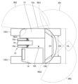
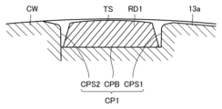
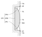
- FIG. 4 is a cross-sectional view taken along line IV-IV in FIG. 4 is a vertical cross-sectional view taken along line VV in FIG. 3.
- FIG. 11 is a rear view of the counterweight showing a modified example in which an object detection sensor is attached to the counterweight.
- the fore-aft direction is the direction in which the boom 16 extends between the base end and the tip end when viewed from above.
- the left-right direction is the direction perpendicular to the fore-aft direction when viewed from above.
- the up-down direction is the direction perpendicular to a plane that includes the fore-aft direction and the left-right direction, which are perpendicular to each other.
- the direction from the base end of the boom 16 to the tip end is the front, and the direction from the tip end of the boom 16 to the base end is the rear.
- the right and left sides are the right and left, respectively.
- the side with the ground is the bottom, and the side with the sky is the top.
- a top view refers to the perspective when the work machine 10 is viewed from above downward.
- a rear view refers to the perspective when the rotating body 13 is viewed from the rear to the front.
- Fig. 1 is a diagram showing a schematic configuration of a work machine according to an embodiment of the present disclosure.
- the work machine 10 according to this embodiment is, for example, a hydraulic excavator, for example, a small hydraulic excavator.
- the work machine 10 according to this embodiment may be, for example, a short swing type or a very short swing type hydraulic excavator.
- the work machine 10 is not limited to a hydraulic excavator, and may be any work machine 10 having a rotating body 13 and a running body 15, in which the rotating body 13 has a curved surface portion that forms a curve when viewed from above.
- a hydraulic excavator 10 which is an example of a work machine 10, has a main body 11 and a work implement 12 that is hydraulically operated.
- the main body 11 has a rotating body 13 and a running body 15.
- the running body 15 has a pair of left and right tracks 15Cr and a running motor 15M.
- the hydraulic excavator 10 can run by rotating the tracks 15Cr.
- the running motor 15M is provided as a drive source for the running body 15.
- the rotating body 13 is placed on the running body 15 and is supported by the running body 15.
- the rotating body 13 can rotate relative to the running body 15 around a rotation axis RX by a rotation motor (not shown).
- the rotation axis RX is an imaginary straight line that serves as the center of rotation of the rotating body 13.
- the rotating body 13 has a driver's cab 14.
- a driver's seat is provided in the driver's cab 14 where the operator sits. The operator sits in the driver's seat in the driver's cab 14 and can operate the work equipment 12, rotate the rotating body 13 relative to the running body 15, and travel the hydraulic excavator 10 using the running body 15.
- the rotating body 13 has an exterior panel 13a, a counterweight CW, and a drive source (e.g., an engine).
- the exterior panel 13a has, for example, an engine hood, a soil cover, a sheet metal cover, etc.
- the counterweight CW is provided to balance the weight of the work implement 12, thereby improving the stability of the main body 11 when the work machine 10 is working.
- the drive source supplies drive force to drive the work implement 12, rotate the rotating body 13, and run the running body 15.
- the drive source is located behind the cab 14.
- the drive source is covered by the exterior panel 13a, the counterweight CW, etc. Note that the drive source is not limited to an engine, and may be a motor driven by a battery.
- the work machine 12 is supported by the rotating body 13.
- the work machine 12 has a boom 16, an arm 17, and a bucket 18.
- the work machine 12 further has a boom cylinder 19a, an arm cylinder 19b, and a bucket cylinder 19c.
- the boom 16 is rotatably connected to the main body 11. Specifically, the base end of the boom 16 is rotatably connected to the rotating body 13 with the boom foot pin BF as a fulcrum. The base end of the boom 16 is disposed to the left and right of the operator's cab 14.
- the arm 17 is rotatably connected to the boom 16. Specifically, the base end of the arm 17 is rotatably connected to the tip of the boom 16 with the boom top pin BT as a fulcrum.
- the bucket 18 is rotatably connected to the arm 17. Specifically, the base end of the bucket 18 is rotatably connected to the tip of the arm 17 with the arm top pin AT as a fulcrum.
- the work machine 10 may also have a blade (not shown) attached to the running body 15.
- FIG. 2 is a top view of the work machine shown in FIG. 1.
- the rotating body 13 has a curved portion CL when viewed from above.
- the curved portion CL is a curved portion of the outer shape of the rotating body 13 when viewed from above.
- the curved portion CL is provided, for example, at the rear of the rotating body 13.
- the curved portion CL is located behind the work machine 12 (boom 16).
- the curved portion CL is also located behind the operator's cab 14.
- the curved surface portion CL is located over the entire rear end of the rotating body 13.
- the curved surface portion CL is located over the entire left-right area at the rear of the rotating body 13. Specifically, the curved surface portion CL is located over the entire area from one side to the other side of the outer shape of the rotating body 13.
- the curved surface portion CL When viewed from above, the curved surface portion CL forms a curved line that protrudes from the inside to the outside of the outer shape of the rotating body 13. In other words, when viewed from above, the curved surface portion CL forms a curved line that protrudes from the inside to the outside of the rotating body 13.
- the curve of the curved surface portion CL when viewed from above may be composed of a curve with a single radius of curvature.
- the curved surface portion CL has, for example, an arc shape centered on the rotation axis RX of the rotating body 13.
- the curved surface portion CL may also be formed from a combination of curves with multiple radii of curvature when viewed from above.
- each of the multiple curves with different radii of curvature forms a convex curve from the inside to the outside of the outer shape of the rotating body 13.
- the work machine 10 of this embodiment has an object detection sensor for detecting objects around the work machine 10.
- the work machine 10 issues a warning to the operator, or controls the turning movement and the operation of the work implement 12 to slow down or stop.
- the object detection sensor employed in the work machine 10 of this embodiment will be described below with reference to Figures 1 to 6.
- the work machine 10 of this embodiment has a first object detection sensor RD1, a second object detection sensor RD2, and a third object detection sensor RD3.
- Each of the first object detection sensor RD1, the second object detection sensor RD2, and the third object detection sensor RD3 is a sensor that detects objects (including people) in the vicinity of the work machine 10.
- Each of the object detection sensors RD1, RD2, RD3 may be, for example, a radar (Radio Detection and Ranging) that acquires information about an object by emitting radio waves.
- Each of the object detection sensors RD1, RD2, RD3 may be, for example, a LiDAR (Light Detection and Ranging) that acquires information about an object by emitting laser light.
- Each of the object detection sensors RD1, RD2, RD3 may be, for example, a millimeter wave radar that uses a receiving antenna to detect how millimeter wave band radio waves emitted from a transmitting antenna are reflected off the surface of an object and returned.
- Each of the object detection sensors RD1, RD2, RD3 may be, for example, a visual sensor including a camera, or an infrared sensor.
- the first object detection sensor RD1 and the second object detection sensor RD2 are arranged on the curved surface portion CL that forms a curve in the outer shape of the rotating body 13 when viewed from above.
- the first object detection sensor RD1 and the second object detection sensor RD2 are arranged on the curved surface portion CL so as to be spaced apart from each other when viewed from above.
- the first object detection sensor RD1 is located directly above one of the pair of tracks 15Cr (first track 15Cr), and the second object detection sensor RD2 is located directly above the other of the pair of tracks 15Cr (second track 15Cr).
- the left-right distance D1 between the first object detection sensor RD1 and the second object detection sensor RD2 is larger than the left-right distance D2 between the pair of tracks 15Cr.
- the distance D1 is the minimum dimension of an imaginary line when the first object detection sensor RD1 and the second object detection sensor RD2 are connected by an imaginary line.
- the distance D2 is also the minimum dimension of an imaginary line when the pair of tracks 15Cr are connected by an imaginary line.
- the third object detection sensor RD3 is disposed on the side of the rotating body 13.
- the third object detection sensor RD3 is located to the left and right of the boom 16 and boom cylinder 19a of the work machine 12.
- the third object detection sensor RD3 is disposed on the opposite side of the work machine 12 from the cab 14.
- the third object detection sensor RD3 is located forward of the first object detection sensor RD1 and the second object detection sensor RD2 and near the work machine 12.
- Each of the object detection sensors RD1 to RD3 is positioned so that it can detect objects outside the rotating body 13.
- the detection range IR1 of the first object detection sensor RD1 is the right side and rear side of the rotating body 13.
- the detection range IR2 of the second object detection sensor RD2 is the left side and rear side of the rotating body 13.
- the detection range IR1 of the first object detection sensor RD1 and the detection range IR2 of the second object detection sensor RD2 overlap each other behind the rotating body 13.
- the detection range IR3 of the third object detection sensor RD3 is on the right side of the rotating body 13.
- the detection range IR3 of the third object detection sensor RD3 and the detection range IR1 of the first object detection sensor RD1 overlap with each other on the right side of the rotating body 13.
- each of the object detection sensors RD1 to RD3 faces, for example, horizontally. If each of the object detection sensors RD1 to RD3 is, for example, a radar, each of the object detection sensors RD1 to RD3 emits radio waves in the horizontal direction. If each of the object detection sensors RD1 to RD3 is, for example, a LiDAR, each of the object detection sensors RD1 to RD3 emits laser light in the horizontal direction. If each of the object detection sensors RD1 to RD3 is, for example, a visual sensor, the optical axis of each of the object detection sensors RD1 to RD3 extends in the horizontal direction. If each of the object detection sensors RD1 to RD3 is, for example, an infrared sensor, each of the object detection sensors RD1 to RD3 emits infrared light in the horizontal direction.
- FIG. 3 is a rear view of the work machine shown in FIG. 1.
- the outer surface of the rotating body 13, except for the driver's cab 14, is mainly composed of the exterior panel 13a and the counterweight CW.
- the curved surface portion CL is composed of a counterweight CW and an exterior panel 13a.
- the first object detection sensor RD1 and the second object detection sensor RD2 are each attached to the exterior panel 13a.
- the first object detection sensor RD1 and the second object detection sensor RD2 are disposed in recesses CP1 and CP2, respectively.
- Each of the recesses CP1 and CP2 is provided in the curved surface portion CL.
- the recesses CP1 and CP2 are provided in the exterior panel 13a.
- Each of the recesses CP1 and CP2 is recessed toward the inside of the rotating body 13.
- the recesses CP1 and CP2 are arranged so as to sandwich the counterweight CW.
- the recesses CP1 and CP2 are arranged so as to be in contact with the counterweight CW.
- the recesses CP1 and CP2 have shapes that are symmetrical to each other with respect to the rotation axis RX when viewed from the rear.
- the first object detection sensor RD1 and the second object detection sensor RD2 are arranged so as to sandwich the counterweight CW.
- the first object detection sensor RD1 and the second object detection sensor RD2 are arranged away from the counterweight CW.
- the first object detection sensor RD1 and the second object detection sensor RD2 may be arranged in contact with the counterweight CW.
- the curved surface portion CL is divided into a lower region RL, a middle region RM, and an upper region RU.
- the middle region RM is located above the lower region RL
- the upper region RU is located above the middle region RM.
- the middle region RM is sandwiched between the lower region RL and the upper region RU.
- Both the first object detection sensor RD1 and the second object detection sensor RD2 are located in the middle region RM.
- the vertical height HC of the curved surface portion CL is the height from the bottom end of the rotating body 13 to the top end of the counterweight CW.
- the bottom end of the rotating body 13 may be the bottom end of the counterweight CW.
- the third object detection sensor RD3 is attached to the exterior panel 13a.
- the third object detection sensor RD3 is disposed in a recess CP3.
- the recess CP3 is provided in the exterior panel 13a.
- the recess CP3 is recessed toward the inside of the rotating body 13.
- the third object detection sensor RD3 is disposed in the middle region RM.
- the third object detection sensor RD3 is disposed at a lower height position in the vertical direction than both the first object detection sensor RD1 and the second object detection sensor RD2.
- the third object detection sensor RD3 may be disposed at the same height position in the vertical direction as both the first object detection sensor RD1 and the second object detection sensor RD2.
- FIGS. 4 and 5 are cross-sectional views taken along lines IV-IV and V-V in FIG. 3, respectively.
- recess CP1 has a bottom wall CPB, one side wall CPS1, the other side wall CPS2, a lower wall CPL, and an upper wall CPU.
- One side wall CPS1, the other side wall CPS2, the lower wall CPL, and the upper wall CPU each extend from the outer surface of the rotating body 13 toward the inside of the rotating body 13.
- the inner ends of one side wall CPS1, the other side wall CPS2, the lower wall CPL, and the upper wall CPU are connected to the bottom wall CPB.
- the bottom wall CPB, one side wall CPS1, lower wall CPL and upper wall CPU are each formed from an exterior panel 13a.
- the other side wall CPS2 is formed from a counterweight CW.
- the other side wall CPS2 may also be formed from an exterior panel 13a.
- the first object detection sensor RD1 is positioned so as to remain within the recess CP1 and does not protrude beyond it.
- the upper end surface TS of the first object detection sensor RD1 is located inside the recess CP1 relative to an imaginary straight line SL connecting the upper end UE and lower end LE of the recess CP1, and does not protrude outside the recess CP1.
- the upper end UE is the connection between the upper wall CPU of the recess CP1 and the outer surface of the exterior panel 13a.
- the lower end LE is the connection between the lower wall CPL of the recess CP1 and the outer surface of the exterior panel 13a.
- the second object detection sensor RD2 and the third object detection sensor RD3 are arranged so as to remain within the recesses CP2 and CP3, respectively, and are configured so as not to protrude from the recesses CP2 and CP3.
- the first object detection sensor RD1 and the second object detection sensor RD2 are described as being attached to the exterior panel 13a, but they may also be attached to the counterweight CW.
- Figure 6 is a rear view of the counterweight showing a modified example in which an object detection sensor is attached to the counterweight.
- recesses CP1 and CP2 are provided in the counterweight CW.
- Each of the recesses CP1 and CP2 is positioned so as to reach both side ends of the counterweight CW.
- Each of the recesses CP1 and CP2 is recessed from the outer surface of the rotating body 13 toward the inside of the rotating body 13.
- the first object detection sensor RD1 is positioned in the recess CP1.
- the second object detection sensor RD2 is positioned in the recess CP2.
- the first object detection sensor RD1 and the second object detection sensor RD2 are arranged at intervals from each other on the curved surface portion CL that forms a curve in the outer shape of the rotating body 13 when viewed from above. This makes it possible to detect objects in a wide range around the rotating body 13 with a small number of object detection sensors.
- the curved surface portion CL forms a convex curve from the inside to the outside of the outer shape of the rotating body 13 when viewed from above. This prevents the curved surface portion CL of the rotating body 13 from obstructing the detection range of the object detection sensors RD1 and RD2.
- the rotating body 13 has recesses CP1 and CP2 in a portion of the height direction of the curved surface portion CL.
- the first object detection sensor RD1 and the second object detection sensor RD2 are disposed in the recesses CP1 and CP2, respectively. This prevents the first object detection sensor RD1 and the second object detection sensor RD2 from protruding outward from the outer surface of the rotating body 13. This prevents the first object detection sensor RD1 and the second object detection sensor RD2 from interfering with obstacles outside the rotating body 13.
- the object detection sensors RD1, RD2 are installed too low, there is a possibility that they may erroneously detect parts of the work machine 10, such as the blade (not shown) attached to the running body 15, as an obstacle. Also, if the object detection sensors RD1, RD2 are installed too high, they will be unable to detect objects near the ground (such as a person standing on the ground) unless the object detection sensors RD1, RD2 are facing downward. However, if the object detection sensors RD1, RD2 are facing downward, there is a possibility that they may erroneously detect the ground as an obstacle.
- both the first object detection sensor RD1 and the second object detection sensor RD2 are disposed in the middle region RM between the lower region RL and the upper region RU. This prevents the first object detection sensor RD1 and the second object detection sensor RD2 from erroneously detecting a part of the work machine 10 and the ground as an obstacle.
- the third object detection sensor RD3 is disposed on the side of the rotating body 13 opposite the cab 14 with respect to the work machine 12 in a top view. This makes it possible to compensate for the blind spot of the operator in the cab 14 by detection by the third object detection sensor RD3.
- the third object detection sensor RD3 is disposed in the middle region RM sandwiched between the lower region RL and the upper region RU. This prevents the third object detection sensor RD3 from erroneously detecting a part of the work machine 10 or the ground as an obstacle.
- both the first object detection sensor RD1 and the second object detection sensor RD2 may be disposed on the counterweight CW. Also, as shown in FIG. 1 and FIG. 3, both the first object detection sensor RD1 and the second object detection sensor RD2 may be disposed on the exterior panel 13a. This reduces restrictions on the placement of the first object detection sensor RD1 and the second object detection sensor RD2, increasing the freedom of design.
- Appendix 1 A running body, A rotating body disposed on the running body and rotating relative to the running body;
- a work machine comprising: a first object detection sensor and a second object detection sensor arranged at a distance from each other on a curved surface portion that forms a curved line in the external shape of the rotating body when viewed from above.
- the rotating body has a recess in a part of the curved surface portion in a height direction, 3.
- the work machine according to claim 1 or 2 wherein each of the first object detection sensor and the second object detection sensor is disposed within the recess.
- the rotating body has a cab, A work machine supported on the rotating body;
- the work machine according to any one of Supplementary Note 1 to Supplementary Note 3, further comprising: a third object detection sensor arranged on a side of the rotating body opposite the operator's cab with respect to the work machine in a top view.
- Appendix 6 The work machine described in Appendix 5, wherein when the curved surface portion is divided into thirds in the vertical direction into a lower region, a middle region, and an upper region, the third object detection sensor is arranged in the middle region that is sandwiched between the lower region and the upper region.
- the rotating body has a counterweight, 7.
- the rotating body has a counterweight and an exterior panel made of a separate member from the counterweight, 7.
- the work machine according to any one of Supplementary Note 1 to Supplementary Note 6, wherein both the first object detection sensor and the second object detection sensor are disposed on the exterior panel.
Landscapes
- Engineering & Computer Science (AREA)
- Mining & Mineral Resources (AREA)
- Civil Engineering (AREA)
- General Engineering & Computer Science (AREA)
- Structural Engineering (AREA)
- Component Parts Of Construction Machinery (AREA)
Abstract
旋回体(13)は、走行体(15)の上に配置され、走行体(15)に対して旋回する。第1物体検出センサ(RD1)および第2物体検出センサ(RD2)は、上面視において旋回体(13)の外形のうち曲線をなす曲面部(CL)に互いに間隔を空けて配置されている。
Description
本開示は、作業機械に関する。
レーダーなどの物体検出センサを有する作業機械は、たとえば特開2002-48490号公報(特許文献1)に開示されている。特許文献1の作業機械では、作業機械の周囲を監視するために複数のレーダーが取付けられている。
しかしながら特許文献1では、作業機械の全周をカバーするために多数のレーダーが必要であった。
本開示の目的は、少ない物体検出センサの個数で周囲の広い範囲を監視できる作業機械を提供することである。
本開示の作業機械は、走行体と、旋回体と、第1物体検出センサと、第2物体検出センサとを備えている。旋回体は、走行体の上に配置され、走行体に対して旋回する。第1物体検出センサおよび第2物体検出センサは、上面視において旋回体の外形のうち曲線をなす曲面部に互いに間隔を空けて配置されている。
本開示によれば、少ない物体検出センサの個数で周囲の広い範囲を監視できる作業機械を実現することができる。
以下、本開示の実施の形態について、図面に基づいて説明する。
明細書および図面において、同一の構成要素または対応する構成要素には、同一の符号を付し、重複する説明を繰り返さない。また、図面では、説明の便宜上、構成を省略または簡略化している場合もある。また、実施の形態と変形例との少なくとも一部は、互いに任意に組み合わされてもよい。
明細書および図面において、同一の構成要素または対応する構成要素には、同一の符号を付し、重複する説明を繰り返さない。また、図面では、説明の便宜上、構成を省略または簡略化している場合もある。また、実施の形態と変形例との少なくとも一部は、互いに任意に組み合わされてもよい。
なお以下において前後方向とは、上面視においてブーム16が基端部と先端部との間で延びる方向である。左右方向とは、上面視において前後方向と直交する方向である。上下方向とは、互いに直交する前後方向と左右方向とを含む平面に直交する方向である。
ブーム16の基端部から先端部へ向かう方向が前方であり、ブーム16の先端部から基端部へ向かう方向が後方である。後方から前方を見る視点において右側、左側がそれぞれ右方、左方である。上下方向において地面のある側が下方であり、空のある側が上方である。上面視とは、作業機械10を上から下に見る視点を意味する。後面視とは、旋回体13を後から前へ見る視点を意味する。
<作業機械10の構成>
図1は、本開示の一実施形態における作業機械の構成を概略的に示す図である。図1に示されるように、本実施形態の作業機械10は、たとえば油圧ショベルであり、たとえば小型の油圧ショベルである。本実施形態の作業機械10は、たとえば後方小旋回型または超小旋回型の油圧ショベルであってもよい。ただし作業機械10は油圧ショベルに限定されず、旋回体13と走行体15とを有し、旋回体13が上面視において曲線をなす曲面部を有する作業機械10であればよい。
図1は、本開示の一実施形態における作業機械の構成を概略的に示す図である。図1に示されるように、本実施形態の作業機械10は、たとえば油圧ショベルであり、たとえば小型の油圧ショベルである。本実施形態の作業機械10は、たとえば後方小旋回型または超小旋回型の油圧ショベルであってもよい。ただし作業機械10は油圧ショベルに限定されず、旋回体13と走行体15とを有し、旋回体13が上面視において曲線をなす曲面部を有する作業機械10であればよい。
作業機械10の一例としての油圧ショベル10は、本体11と、油圧により作動する作業機12とを有している。本体11は、旋回体13と、走行体15とを有している。
走行体15は、左右一対の履帯15Crと、走行モータ15Mとを有している。油圧ショベル10は、履帯15Crの回転により走行可能である。走行モータ15Mは、走行体15の駆動源として設けられている。
旋回体13は、走行体15の上に配置され、かつ走行体15により支持されている。旋回体13は、旋回モータ(図示せず)により旋回軸RXを中心として走行体15に対して旋回可能である。旋回軸RXは、旋回体13の旋回中心となる仮想の直線である。
旋回体13は、運転室14(キャブ)を有している。運転室14内には、オペレータが着座する運転席が設けられている。オペレータは、運転室14内の運転席に着座して、作業機12の操作、走行体15に対する旋回体13の旋回操作、および走行体15による油圧ショベル10の走行操作を可能である。
旋回体13は、外装パネル13aと、カウンターウエイトCWと、駆動源(たとえばエンジン)とを有している。外装パネル13aは、たとえばエンジンフード、土砂カバー、板金カバーなどを有している。カウンターウエイトCWは、作業機12による偏った重さのつり合いをとることにより、作業機械10の作業時における本体11の安定を良くするために設けられている。駆動源は、作業機12の駆動、旋回体13の旋回、走行体15の走行などに駆動力を供給する。駆動源は、運転室14の後方に配置されている。駆動源の周囲は、外装パネル13a、カウンターウエイトCWなどにより覆われている。なお駆動源はエンジンに限定されず、バッテリーにより駆動するモータであってもよい。
作業機12は、旋回体13に支持されている。作業機12は、ブーム16と、アーム17と、バケット18とを有している。作業機12は、ブームシリンダ19aと、アームシリンダ19bと、バケットシリンダ19cとをさらに有している。
ブーム16は、本体11に回動可能に接続されている。具体的にはブーム16の基端部は、ブームフートピンBFを支点として旋回体13に回動可能に接続されている。ブーム16の基端部は、運転室14の左右方向に配置されている。アーム17は、ブーム16に回動可能に接続されている。具体的にはアーム17の基端部は、ブームトップピンBTを支点としてブーム16の先端部に回動可能に接続されている。バケット18は、アーム17に回転可能に接続されている。具体的にはバケット18の基端部は、アームトップピンATを支点としてアーム17の先端部に回動可能に接続されている。
なお作業機械10は、走行体15に取付けられたブレード(図示せず)を有していてもよい。
図2は、図1に示す作業機械の上面図である。図2に示されるように、上面視において旋回体13は曲面部CLを有している。曲面部CLは、上面視において旋回体13の外形のうち曲線をなす部分である。曲面部CLは、たとえば旋回体13の後部に設けられている。曲面部CLは、作業機12(ブーム16)の後方に位置している。また曲面部CLは、運転室14の後方に位置している。
曲面部CLは、旋回体13の後端全体に位置している。曲面部CLは、旋回体13の後部において左右方向の全体に位置している。具体的には、曲面部CLは、旋回体13の外形における一方側部から他方側部に亘って全体的に位置している。
曲面部CLは、上面視において、旋回体13の外形の内側から外側に向かって凸の曲線を構成している。つまり曲面部CLは、上面視において、旋回体13の内側から外側に向かって突き出すような曲線を構成している。
上面視における曲面部CLの曲線は、単一の曲率半径の曲線から構成されていてもよい。曲面部CLは、上面視においてたとえば旋回体13の旋回軸RXを中心とした円弧形状を有している。
また曲面部CLは、上面視において、複数の曲率半径の曲線の組合わせから構成されていてもよい。曲面部CLが複数の曲率半径の曲線の組合わせからなる場合、曲率半径が互いに異なる複数の曲線の各々が、旋回体13の外形の内側から外側に向かって凸の曲線を構成している。
本実施形態の作業機械10は、作業機械10の周囲の物体を検出するために物体検出センサを有している。物体検出センサにより作業機械10の周囲に物体を検出した場合、作業機械10は、オペレータに警告を発報する、または旋回動作および作業機12の動作を減速または停止するように制御する。以下、本実施形態の作業機械10に採用される物体検出センサについて図1~図6を用いて説明する。
図2に示されるように、本実施形態の作業機械10は、第1物体検出センサRD1と、第2物体検出センサRD2と、第3物体検出センサRD3とを有している。第1物体検出センサRD1、第2物体検出センサRD2および第3物体検出センサRD3の各々は、作業機械10の周辺の物体(人を含む)を検出するセンサである。
物体検出センサRD1、RD2、RD3の各々は、たとえば電波を射出することにより対象物の情報を取得するレーダー(Radio Detection and Ranging)である。物体検出センサRD1、RD2、RD3の各々は、たとえばレーザ光を射出して対象物の情報を取得するLiDAR(Light Detection and Ranging)であってもよい。また物体検出センサRD1、RD2、RD3の各々は、たとえば送信アンテナから発したミリ波帯の電波が物体の表面で反射して戻ってくる様子を受信アンテナで検出するミリ波レーダーであってもよい。また物体検出センサRD1、RD2、RD3の各々は、たとえばカメラを含む視覚センサであってもよく、また赤外線センサであってもよい。
第1物体検出センサRD1および第2物体検出センサRD2は、上面視において旋回体13の外形のうち曲線をなす曲面部CLに配置されている。第1物体検出センサRD1および第2物体検出センサRD2は、上面視において互いに間隔を空けるように曲面部CLに配置されている。
ブーム16の基端部から先端部へ延びる方向と履帯15Crが延びる方向とが平行な状態において、第1物体検出センサRD1は左右1対の履帯15Crの一方(第1履帯15Cr)の真上に位置し、第2物体検出センサRD2は左右1対の履帯15Crの他方(第2履帯15Cr)の真上に位置している。上面視において、第1物体検出センサRD1と第2物体検出センサRD2との左右方向の間隔D1は、左右1対の履帯15Crの左右方向の間隔D2よりも大きい。間隔D1は、第1物体検出センサRD1と第2物体検出センサRD2とを仮想の直線で繋いだときの仮想の直線の最小寸法である。また間隔D2は、左右1対の履帯15Crを仮想の直線で繋いだときの仮想の直線の最小寸法である。
第3物体検出センサRD3は、旋回体13の側部に配置されている。第3物体検出センサRD3は、作業機12のブーム16およびブームシリンダ19aの左右方向に位置している。第3物体検出センサRD3は、作業機12に対して運転室14とは反対側に配置されている。第3物体検出センサRD3は、第1物体検出センサRD1および第2物体検出センサRD2よりも前方であって作業機12の近くに位置している。
物体検出センサRD1~RD3の各々は、旋回体13の外部の物体を検出できるように配置されている。第1物体検出センサRD1の検出範囲IR1は、旋回体13の右側および後側である。第2物体検出センサRD2の検出範囲IR2は、旋回体13の左側および後側である。第1物体検出センサRD1の検出範囲IR1と第2物体検出センサRD2の検出範囲IR2とは、旋回体13の後方において互いに重複する。
第3物体検出センサRD3の検出範囲IR3は、旋回体13の右側である。第3物体検出センサRD3の検出範囲IR3と第1物体検出センサRD1の検出範囲IR1とは、旋回体13の右側において互いに重複する。
作業機械10が水平な地面に置かれている場合、物体検出センサRD1~RD3の各々は、たとえば水平方向に向いている。物体検出センサRD1~RD3の各々がたとえばレーダーである場合、物体検出センサRD1~RD3の各々は水平方向に向かって電波を射出する。また物体検出センサRD1~RD3の各々がたとえばLiDARである場合、物体検出センサRD1~RD3の各々は水平方向に向かってレーザ光を射出する。また物体検出センサRD1~RD3の各々がたとえば視覚センサである場合、物体検出センサRD1~RD3の各々の光軸は水平方向に向かって延びている。また物体検出センサRD1~RD3の各々がたとえば赤外線センサである場合、物体検出センサRD1~RD3の各々は水平方向に向かって赤外線を射出する。
図3は、図1に示す作業機械の後面図である。図1~図3に示されるように、旋回体13の外表面は、運転室14の部分を除いて、外装パネル13aとカウンターウエイトCWとにより主に構成されている。
図3に示されるように、曲面部CLは、カウンターウエイトCWと、外装パネル13aとにより構成されている。第1物体検出センサRD1および第2物体検出センサRD2の各々は、外装パネル13aに取付けられている。第1物体検出センサRD1および第2物体検出センサRD2は、それぞれ凹部CP1および凹部CP2に配置されている。凹部CP1、CP2の各々は、曲面部CLに設けられている。凹部CP1、CP2は、外装パネル13aに設けられている。凹部CP1、CP2の各々は、旋回体13の内側に向かって窪んでいる。
凹部CP1、CP2の各々は、カウンターウエイトCWを挟み込むように配置されている。凹部CP1、CP2の各々は、たとえばカウンターウエイトCWに接するように配置されている。凹部CP1、CP2は、後面視において旋回軸RXに対して互いに線対称形状を有している。
第1物体検出センサRD1および第2物体検出センサRD2の各々は、カウンターウエイトCWを挟み込むように配置されている。第1物体検出センサRD1および第2物体検出センサRD2の各々は、カウンターウエイトCWから離れて配置されている。第1物体検出センサRD1および第2物体検出センサRD2の各々は、カウンターウエイトCWに接して配置されていてもよい。
曲面部CLの上下方向の高さHCを3等分することにより、曲面部CLは、下領域RLと、中領域RMと、上領域RUとに区分けされる。下領域RLの上に中領域RMが位置し、中領域RMの上に上領域RUが位置している。中領域RMは、下領域RLと上領域RUとに挟まれている。第1物体検出センサRD1および第2物体検出センサRD2の双方は中領域RMに配置されている。
なお曲面部CLの上下方向の高さHCは、旋回体13の下端からカウンターウエイトCWの上端までの高さである。旋回体13の下端は、カウンターウエイトCWの下端であってもよい。
図1に示されるように、第3物体検出センサRD3は、外装パネル13aに取付けられている。第3物体検出センサRD3は、凹部CP3に配置されている。凹部CP3は、外装パネル13aに設けられている。凹部CP3は、旋回体13の内側に向かって窪んでいる。
第3物体検出センサRD3は中領域RMに配置されている。第3物体検出センサRD3は、第1物体検出センサRD1および第2物体検出センサRD2の双方よりも上下方向の低い高さ位置に配置されている。第3物体検出センサRD3は、第1物体検出センサRD1および第2物体検出センサRD2の双方と上下方向の同じ高さ位置に配置されていてもよい。
図4および図5は、それぞれ図3のIV-IV線およびV-V線に沿う断面図である。図4および図5に示されるように、凹部CP1は、底壁CPBと、一方側壁CPS1と、他方側壁CPS2と、下壁CPLと、上壁CPUとを有している。一方側壁CPS1、他方側壁CPS2、下壁CPLおよび上壁CPUの各々は、旋回体13の外表面から旋回体13の内側へ延びている。一方側壁CPS1、他方側壁CPS2、下壁CPLおよび上壁CPUの各々の内側端は底壁CPBに接続されている。
底壁CPB、一方側壁CPS1、下壁CPLおよび上壁CPUの各々は、外装パネル13aにより構成されている。他方側壁CPS2は、カウンターウエイトCWにより構成されている。なお他方側壁CPS2は、外装パネル13aにより構成されていてもよい。
第1物体検出センサRD1は、凹部CP1内に留まるように配置されており、凹部CP1から突き出さない。つまり図5に示されるように第1物体検出センサRD1の上端面TSは、凹部CP1の上端UEと下端LEとを繋ぐ仮想の直線SLよりも凹部CP1の内側に位置し、凹部CP1の外側に突き出さない。上端UEとは、凹部CP1の上壁CPUと外装パネル13aの外表面との接続部である。また下端LEとは、凹部CP1の下壁CPLと外装パネル13aの外表面との接続部である。
なお第2物体検出センサRD2および第3物体検出センサRD3のそれぞれについても、第1物体検出センサRD1と同様、凹部CP2および凹部CP3内に留まるように配置されており、凹部CP2および凹部CP3から突き出さないように構成されている。
上記においては第1物体検出センサRD1および第2物体検出センサRD2の各々は、外装パネル13aに取付けられた場合について説明したが、カウンターウエイトCWに取り付けられていてもよい。
図6は、物体検出センサがカウンターウエイトに取付けられた変形例を示すカウンターウエイトの後面図である。図6に示されるように、カウンターウエイトCWに凹部CP1、CP2が設けられている。凹部CP1、CP2の各々は、カウンターウエイトCWの両側端に達するように配置されている。凹部CP1、CP2の各々は、旋回体13の外表面から旋回体13の内側に向かって窪んでいる。第1物体検出センサRD1は、凹部CP1内に配置されている。第2物体検出センサRD2は、凹部CP2内に配置されている。
なお図6に示された変形例の構成のうち上記以外の構成については図1~図5に示す構成とほぼ同じであるため、同一の要素については同一の符号を付し、その説明を繰り返さない。
<効果>
次に、本実施形態の効果について説明する。
次に、本実施形態の効果について説明する。
本実施形態においては図2に示されるように、第1物体検出センサRD1および第2物体検出センサRD2の各々は、上面視において旋回体13の外形のうち曲線をなす曲面部CLに互いに間隔を空けて配置されている。このため少ない物体検出センサの個数で旋回体13の周囲を広い範囲において物体を検出することが可能となる。
また本実施形態においては図2に示されるように、曲面部CLは、上面視において旋回体13の外形の内側から外側に向かって凸の曲線を構成する。これにより旋回体13の曲面部CLが物体検出センサRD1、RD2の検出範囲の障害となることは抑制される。
また本実施形態においては図2に示されるように、旋回体13は、曲面部CLの高さ方向の一部に凹部CP1、CP2を有している。第1物体検出センサRD1および第2物体検出センサRD2のそれぞれは、凹部CP1および凹部CP2内に配置されている。これにより第1物体検出センサRD1および第2物体検出センサRD2の各々が、旋回体13の外表面から外側に突き出すことが抑制される。このため第1物体検出センサRD1および第2物体検出センサRD2の各々が、旋回体13の外部の障害物と干渉することが抑制される。
物体検出センサRD1、RD2の取付け高さが低すぎると、走行体15に取付けられたブレード(図示せず)などの作業機械10の一部を障害物として誤検知する可能性がある。また物体検出センサRD1、RD2の取付け高さが高すぎると、物体検出センサRD1、RD2を下向きにしないと地面付近の物体(たとえば地面に立つ人など)を検出できなくなる。しかし物体検出センサRD1、RD2を下向きにすると地面を障害物として誤検知する可能性がある。
本実施形態においては図3に示されるように、第1物体検出センサRD1および第2物体検出センサRD2の双方は、下領域RLと上領域RUとに挟まれる中領域RMに配置されている。これにより第1物体検出センサRD1および第2物体検出センサRD2の各々が、作業機械10の一部および地面を障害物として誤検知することが抑制される。
また本実施形態においては図2に示されるように、第3物体検出センサRD3は、上面視において作業機12に対して運転室14とは反対側の旋回体13の側面に配置されている。これにより運転室14に搭乗するオペレータの死角を第3物体検出センサRD3の検出により補うことができる。
また本実施形態においては図1に示されるように、第3物体検出センサRD3は、曲面部CLを上下方向に3等分して下領域RLと中領域RMと上領域RUとに区分けした場合に、下領域RLと上領域RUとに挟まれる中領域RMに配置されている。これにより第3物体検出センサRD3が、作業機械10の一部および地面を障害物として誤検知することが抑制される。
また本実施形態においては図6に示されるように、第1物体検出センサRD1および第2物体検出センサRD2の双方は、カウンターウエイトCWに配置されていてもよい。また図1、図3に示されるように、第1物体検出センサRD1および第2物体検出センサRD2の双方は、外装パネル13aに配置されていてもよい。これにより第1物体検出センサRD1および第2物体検出センサRD2の配置位置の制約が少なくなり、設計の自由度が高まる。
<付記>
上述したような実施形態は、以下のような技術思想を含む。
上述したような実施形態は、以下のような技術思想を含む。
(付記1)
走行体と、
前記走行体の上に配置され、前記走行体に対して旋回する旋回体と、
上面視において前記旋回体の外形のうち曲線をなす曲面部に互いに間隔を空けて配置された第1物体検出センサおよび第2物体検出センサと、を備えた、作業機械。
走行体と、
前記走行体の上に配置され、前記走行体に対して旋回する旋回体と、
上面視において前記旋回体の外形のうち曲線をなす曲面部に互いに間隔を空けて配置された第1物体検出センサおよび第2物体検出センサと、を備えた、作業機械。
(付記2)
前記曲面部は、上面視において前記旋回体の外形の内側から外側に向かって凸の曲線を構成する、付記1に記載の作業機械。
前記曲面部は、上面視において前記旋回体の外形の内側から外側に向かって凸の曲線を構成する、付記1に記載の作業機械。
(付記3)
前記旋回体は、前記曲面部の高さ方向の一部に凹部を有し、
前記第1物体検出センサおよび前記第2物体検出センサの各々は、前記凹部内に配置されている、付記1または付記2に記載の作業機械。
前記旋回体は、前記曲面部の高さ方向の一部に凹部を有し、
前記第1物体検出センサおよび前記第2物体検出センサの各々は、前記凹部内に配置されている、付記1または付記2に記載の作業機械。
(付記4)
前記第1物体検出センサおよび前記第2物体検出センサの双方は、前記曲面部を上下方向に3等分することにより下領域と中領域と上領域とに区分けした場合、前記下領域と前記上領域とに挟まれる前記中領域に配置されている、付記1から付記3のいずれか1つに記載の作業機械。
前記第1物体検出センサおよび前記第2物体検出センサの双方は、前記曲面部を上下方向に3等分することにより下領域と中領域と上領域とに区分けした場合、前記下領域と前記上領域とに挟まれる前記中領域に配置されている、付記1から付記3のいずれか1つに記載の作業機械。
(付記5)
前記旋回体は、運転室を有し、
前記旋回体に支持された作業機と、
上面視において前記作業機に対して前記運転室とは反対側の前記旋回体の側面に配置された第3物体検出センサと、をさらに備えた、付記1から付記3のいずれか1つに記載の作業機械。
前記旋回体は、運転室を有し、
前記旋回体に支持された作業機と、
上面視において前記作業機に対して前記運転室とは反対側の前記旋回体の側面に配置された第3物体検出センサと、をさらに備えた、付記1から付記3のいずれか1つに記載の作業機械。
(付記6)
前記第3物体検出センサは、前記曲面部を上下方向に3等分することにより下領域と中領域と上領域とに区分けした場合、前記下領域と前記上領域とに挟まれる前記中領域に配置されている、付記5に記載の作業機械。
前記第3物体検出センサは、前記曲面部を上下方向に3等分することにより下領域と中領域と上領域とに区分けした場合、前記下領域と前記上領域とに挟まれる前記中領域に配置されている、付記5に記載の作業機械。
(付記7)
前記旋回体は、カウンターウエイトを有し、
前記第1物体検出センサおよび前記第2物体検出センサの双方は、前記カウンターウエイトに配置されている、付記1から付記6のいずれか1つに記載の作業機械。
前記旋回体は、カウンターウエイトを有し、
前記第1物体検出センサおよび前記第2物体検出センサの双方は、前記カウンターウエイトに配置されている、付記1から付記6のいずれか1つに記載の作業機械。
(付記8)
前記旋回体は、カウンターウエイトと、前記カウンターウエイトとは別部材からなる外装パネルとを有し、
前記第1物体検出センサおよび前記第2物体検出センサの双方は、前記外装パネルに配置されている、付記1から付記6のいずれか1つに記載の作業機械。
前記旋回体は、カウンターウエイトと、前記カウンターウエイトとは別部材からなる外装パネルとを有し、
前記第1物体検出センサおよび前記第2物体検出センサの双方は、前記外装パネルに配置されている、付記1から付記6のいずれか1つに記載の作業機械。
今回開示された実施の形態はすべての点で例示であって制限的なものではないと考えられるべきである。本発明の範囲は上記した説明ではなくて請求の範囲によって示され、請求の範囲と均等の意味および範囲内でのすべての変更が含まれることが意図される。
10 作業機械、11 本体、12 作業機、13 旋回体、13a 外装パネル、14 運転室、15 走行体、15Cr 履帯、15M 走行モータ、16 ブーム、17 アーム、18 バケット、19a ブームシリンダ、19b アームシリンダ、19c バケットシリンダ、AT アームトップピン、BF ブームフートピン、BT ブームトップピン、CL 曲面部、CP1,CP2,CP3 凹部、CPB 底壁、CPL 下壁、CPS1 一方側壁、CPS2 他方側壁、CPU 上壁、CW カウンターウエイト、LE 下端、RD1 第1物体検出センサ、RD2 第2物体検出センサ、RD3 第3物体検出センサ、RL 下領域、RM 中領域、RU 上領域、RX 旋回軸、TS 上端面、UE 上端。
Claims (8)
- 走行体と、
前記走行体の上に配置され、前記走行体に対して旋回する旋回体と、
上面視において前記旋回体の外形のうち曲線をなす曲面部に互いに間隔を空けて配置された第1物体検出センサおよび第2物体検出センサと、を備えた、作業機械。 - 前記曲面部は、上面視において前記旋回体の外形の内側から外側に向かって凸の曲線を構成する、請求項1に記載の作業機械。
- 前記旋回体は、前記曲面部の高さ方向の一部に凹部を有し、
前記第1物体検出センサおよび前記第2物体検出センサの各々は、前記凹部内に配置されている、請求項1に記載の作業機械。 - 前記第1物体検出センサおよび前記第2物体検出センサの双方は、前記曲面部を上下方向に3等分することにより下領域と中領域と上領域とに区分けした場合、前記下領域と前記上領域とに挟まれる前記中領域に配置されている、請求項1に記載の作業機械。
- 前記旋回体は、運転室を有し、
前記旋回体に支持された作業機と、
上面視において前記作業機に対して前記運転室とは反対側の前記旋回体の側面に配置された第3物体検出センサと、をさらに備えた、請求項1に記載の作業機械。 - 前記第3物体検出センサは、前記曲面部を上下方向に3等分することにより下領域と中領域と上領域とに区分けした場合、前記下領域と前記上領域とに挟まれる前記中領域に配置されている、請求項5に記載の作業機械。
- 前記旋回体は、カウンターウエイトを有し、
前記第1物体検出センサおよび前記第2物体検出センサの双方は、前記カウンターウエイトに配置されている、請求項1に記載の作業機械。 - 前記旋回体は、カウンターウエイトと、前記カウンターウエイトとは別部材からなる外装パネルとを有し、
前記第1物体検出センサおよび前記第2物体検出センサの双方は、前記外装パネルに配置されている、請求項1に記載の作業機械。
Applications Claiming Priority (2)
| Application Number | Priority Date | Filing Date | Title |
|---|---|---|---|
| JP2023-127087 | 2023-08-03 | ||
| JP2023127087A JP2025022474A (ja) | 2023-08-03 | 2023-08-03 | 作業機械 |
Publications (1)
| Publication Number | Publication Date |
|---|---|
| WO2025028343A1 true WO2025028343A1 (ja) | 2025-02-06 |
Family
ID=94395259
Family Applications (1)
| Application Number | Title | Priority Date | Filing Date |
|---|---|---|---|
| PCT/JP2024/026283 Pending WO2025028343A1 (ja) | 2023-08-03 | 2024-07-23 | 作業機械 |
Country Status (2)
| Country | Link |
|---|---|
| JP (1) | JP2025022474A (ja) |
| WO (1) | WO2025028343A1 (ja) |
Citations (10)
| Publication number | Priority date | Publication date | Assignee | Title |
|---|---|---|---|---|
| JP2006016914A (ja) * | 2004-07-05 | 2006-01-19 | Hitachi Constr Mach Co Ltd | 後方監視カメラ装置 |
| JP2008184789A (ja) * | 2007-01-30 | 2008-08-14 | Shin Caterpillar Mitsubishi Ltd | 作業車の後方監視カメラ装置 |
| JP2009167747A (ja) * | 2008-01-18 | 2009-07-30 | Komatsu Ltd | 監視カメラ装置 |
| JP2013073514A (ja) * | 2011-09-28 | 2013-04-22 | Sumitomo Heavy Ind Ltd | 画像生成方法、画像生成装置、及び操作支援システム |
| JP2013189778A (ja) * | 2012-03-13 | 2013-09-26 | Kobelco Contstruction Machinery Ltd | 建設機械のカウンタウェイト装置 |
| JP2018135759A (ja) * | 2018-06-07 | 2018-08-30 | 住友重機械工業株式会社 | 作業機械用周辺監視装置 |
| JP2019035277A (ja) * | 2017-08-18 | 2019-03-07 | コベルコ建機株式会社 | 建設機械 |
| JP2019071677A (ja) * | 2019-01-28 | 2019-05-09 | 住友重機械工業株式会社 | ショベル |
| JP2020183623A (ja) * | 2019-04-26 | 2020-11-12 | 住友建機株式会社 | ショベル |
| JP2022048490A (ja) * | 2020-09-15 | 2022-03-28 | 株式会社小松製作所 | 作業車両 |
-
2023
- 2023-08-03 JP JP2023127087A patent/JP2025022474A/ja active Pending
-
2024
- 2024-07-23 WO PCT/JP2024/026283 patent/WO2025028343A1/ja active Pending
Patent Citations (10)
| Publication number | Priority date | Publication date | Assignee | Title |
|---|---|---|---|---|
| JP2006016914A (ja) * | 2004-07-05 | 2006-01-19 | Hitachi Constr Mach Co Ltd | 後方監視カメラ装置 |
| JP2008184789A (ja) * | 2007-01-30 | 2008-08-14 | Shin Caterpillar Mitsubishi Ltd | 作業車の後方監視カメラ装置 |
| JP2009167747A (ja) * | 2008-01-18 | 2009-07-30 | Komatsu Ltd | 監視カメラ装置 |
| JP2013073514A (ja) * | 2011-09-28 | 2013-04-22 | Sumitomo Heavy Ind Ltd | 画像生成方法、画像生成装置、及び操作支援システム |
| JP2013189778A (ja) * | 2012-03-13 | 2013-09-26 | Kobelco Contstruction Machinery Ltd | 建設機械のカウンタウェイト装置 |
| JP2019035277A (ja) * | 2017-08-18 | 2019-03-07 | コベルコ建機株式会社 | 建設機械 |
| JP2018135759A (ja) * | 2018-06-07 | 2018-08-30 | 住友重機械工業株式会社 | 作業機械用周辺監視装置 |
| JP2019071677A (ja) * | 2019-01-28 | 2019-05-09 | 住友重機械工業株式会社 | ショベル |
| JP2020183623A (ja) * | 2019-04-26 | 2020-11-12 | 住友建機株式会社 | ショベル |
| JP2022048490A (ja) * | 2020-09-15 | 2022-03-28 | 株式会社小松製作所 | 作業車両 |
Also Published As
| Publication number | Publication date |
|---|---|
| JP2025022474A (ja) | 2025-02-14 |
Similar Documents
| Publication | Publication Date | Title |
|---|---|---|
| JP6926020B2 (ja) | 障害物検知システム | |
| JP2019097454A (ja) | 作業車両 | |
| KR102824903B1 (ko) | 트랙터 | |
| WO2020251023A1 (ja) | 作業機械 | |
| US20230313500A1 (en) | Work vehicle | |
| WO2025028343A1 (ja) | 作業機械 | |
| CN212405311U (zh) | 自动行驶工程机械 | |
| JP2015140637A (ja) | 建設機械 | |
| CN211774106U (zh) | 自动行驶工程机械 | |
| JP2019175318A (ja) | 作業車両の走行制御システム | |
| JP7488669B2 (ja) | 高所作業車の安全装置 | |
| JP7795825B2 (ja) | 作業機 | |
| RU2800466C2 (ru) | Поворотная башня с балластом | |
| CN211773983U (zh) | 自动行驶工程机械 | |
| KR102707819B1 (ko) | 자율주행 굴삭기 | |
| US12460387B2 (en) | Work machine | |
| JP3245396B2 (ja) | 建設機械の警報装置 | |
| JP2022096950A (ja) | 作業車両 | |
| JP7713355B2 (ja) | 検知装置および作業機械 | |
| JP2025102233A (ja) | 作業車両 | |
| JP7658794B2 (ja) | 建設機械 | |
| JP7341096B2 (ja) | 作業車両 | |
| JP2026070477A (ja) | 作業機械 | |
| JP3784519B2 (ja) | 超小旋回作業機 | |
| JP2002088819A (ja) | 旋回式建設機械 |
Legal Events
| Date | Code | Title | Description |
|---|---|---|---|
| 121 | Ep: the epo has been informed by wipo that ep was designated in this application |
Ref document number: 24848998 Country of ref document: EP Kind code of ref document: A1 |