WO2025028303A1 - 細胞移動装置 - Google Patents
細胞移動装置 Download PDFInfo
- Publication number
- WO2025028303A1 WO2025028303A1 PCT/JP2024/025937 JP2024025937W WO2025028303A1 WO 2025028303 A1 WO2025028303 A1 WO 2025028303A1 JP 2024025937 W JP2024025937 W JP 2024025937W WO 2025028303 A1 WO2025028303 A1 WO 2025028303A1
- Authority
- WO
- WIPO (PCT)
- Prior art keywords
- tip
- cell
- head
- trace
- container
- Prior art date
- Legal status (The legal status is an assumption and is not a legal conclusion. Google has not performed a legal analysis and makes no representation as to the accuracy of the status listed.)
- Pending
Links
Images







Classifications
-
- C—CHEMISTRY; METALLURGY
- C12—BIOCHEMISTRY; BEER; SPIRITS; WINE; VINEGAR; MICROBIOLOGY; ENZYMOLOGY; MUTATION OR GENETIC ENGINEERING
- C12M—APPARATUS FOR ENZYMOLOGY OR MICROBIOLOGY; APPARATUS FOR CULTURING MICROORGANISMS FOR PRODUCING BIOMASS, FOR GROWING CELLS OR FOR OBTAINING FERMENTATION OR METABOLIC PRODUCTS, i.e. BIOREACTORS OR FERMENTERS
- C12M1/00—Apparatus for enzymology or microbiology
- C12M1/26—Inoculator or sampler
Definitions
- the present invention relates to a cell transfer device that transfers specific target cells from among cells contained in a first container to a second container.
- a cell moving device uses a head equipped with a suction tip to pick and hold a target cell from the culture vessel, and then releases the held cell into the work vessel.
- Patent Document 1 discloses a method for positioning the target cell and the tip opening of the suction tip by performing control to reduce the gap between the suction tip and its projected image to zero.
- Patent Document 1 requires a separate illumination system to create a projected image of the suction tip, which makes the device more complicated and expensive.
- the positioning of the tip opening relative to the target cell cannot be performed accurately to the micron level simply by positioning the suction tip and its projected image.
- the object of the present invention is to provide a cell migration device that can accurately pick target cells.
- a cell moving device is a cell moving device that moves a specific target cell among cells contained in a first container to a second container, and includes a camera that captures images of the cells contained in the first container, a head that is equipped with a tip having a tip that aspirates and discharges cells, moves to the position of the target cell in the first container based on the image captured by the camera, aspirates the target cell into the tip, moves to the second container, and discharges the target cell in the tip into the second container, and an information processing unit that corrects the actual position coordinates of the head.
- the information processing unit sets a calibration area in the first container, and operates the head so that the tip leaves a predetermined trace on the calibration area, with a predetermined location in the calibration area as the target coordinate position to which the head will move, and causes the camera to capture an image of an area including the trace to identify the actual coordinate position of the trace, and obtains a correction value for the position coordinates of the head by calculating the difference between the target coordinate position and the actual coordinate position.
- FIG. 1 is a diagram illustrating an example of the configuration of a cell migration device according to an embodiment of the present invention.
- Figure 2(A) is a cross-sectional view of a chip attached to a head and a diagram showing the moving mechanism and suction mechanism for the chip
- Figure 2(B) is a cross-sectional view of the chip during suction operation
- Figure 2(C) is an enlarged view of the main parts of Figure 2(B).
- FIG. 3 is a block diagram showing the electrical configuration of the cell migration device.
- 4(A) and (B) are diagrams for explaining problems with conventional cell picking.
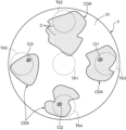
- FIG. 5 is a diagram showing a process for setting a calibration area in the first embodiment.
- FIGS. 6(A) and (B) are diagrams illustrating the operation of forming a trace by pressing the tip of the tip against a cell distribution area.
- 7(A) and (B) are schematic diagrams showing another example of trace formation in a cell distribution area.
- FIG. 8 is a diagram showing a specific example of horizontal movement of the tip in the operation of forming a trace in a cell distribution area.
- FIG. 9 is a diagram showing another example of setting the calibration area.
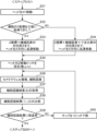
- FIG. 10 is a flowchart showing the cell picking process.
- FIG. 11 is a flowchart showing the correction process.
- FIG. 12 is a flowchart showing the correction process.
- FIG. 13 is a flowchart showing a correction process according to a modified example.
- 14A to 14D are diagrams for explaining the correction process according to the second embodiment of the present invention.
- 15(A) and (B) are diagrams showing preferred examples of the tip end portion.
- the cell migration device can pick and move various types of cells derived from living organisms.
- Cells derived from living organisms include, for example, blood cells, cells such as single cells and fertilized eggs, tissue fragments such as histocultures, cell aggregates such as spheroids and organoids, individuals such as zebrafish and nematodes, and 2D or 3D cell colonies.
- the term "cell” includes these various types of cells.
- the cell migration device of the present invention is suitable for picking and moving cells such as single cells, cell aggregates, and cell colonies, which generally require picking under a microscope.
- FIG. 1 is a diagram showing a schematic diagram of the overall configuration of a cell migration device S according to an embodiment of the present invention.
- a cell migration device S for migrating cells C between two containers i.e., between a culture plate 2 (first container) and a destination plate 4 (second container) is shown as an example.
- the cell migration device S may be configured to migrating cells C between three or more containers.
- the cell movement device S includes a light-transmitting base 1 having a horizontal mounting surface, a camera unit 5 arranged on the lower side of the base 1, and a head unit 6 arranged on the upper side of the base 1.
- a culture plate 2, which is the source of the movement of the cells C, is mounted on the first mounting position P1 of the base 1, and a destination plate 4, which is the destination of the movement of the cells C, is mounted on the second mounting position P2.
- the head unit 6 has multiple heads 61 that can be raised and lowered in the Z direction (up and down direction).
- a chip 10 that sucks and discharges the cells C is attached to the lower end of each head 61.
- the camera unit 5 and head unit 6 can move in the X direction (horizontal direction) and in the direction perpendicular to the paper surface of FIG. 1 (Y direction).
- the culture plate 2 and destination plate 4 are mounted on the upper surface of the base 1 within the movable range of the head unit 6.
- the cell movement device S picks specific target cells C by individually aspirating them into each of the multiple chips 10 from a culture plate 2 in which a large number of cells C are cultured. The picked cells C are then moved to a destination plate 4, and the cells C are ejected from the multiple chips 10 into the destination plate 4 (wells 41). Before picking the cells C, the camera unit 5 captures an image of the cells C held in the culture plate 2, and a sorting operation is performed to select good quality cells C to be moved to the destination plate 4.
- the base 1 is a flat plate having a certain rigidity and formed in part or in whole from a light-transmitting material.
- a preferred base 1 is a glass plate.
- the culture plate 2 is a container from which the cells C are moved, and is provided with multiple wells 3 for culturing the cells C.
- Each well 3 is a small container that is open at the top and has a flat bottom surface 31.
- the cultured cells C are positioned (adhered or floating) on the bottom surface 31.
- Liquid medium LCM is poured into the wells 3, and test cells are seeded therein.
- the culture plate 2 is made of a member made of a translucent resin material or glass, so that the cells C can be imaged by the camera unit 5 disposed below.
- a commercially available 6-well plate for example, Corning model number 3516 can be used.
- the destination plate 4 has a number of wells 41 into which the cells C picked from the culture plate 2 are discharged.
- the wells 41 are bottomed holes that open onto the top surface of the destination plate 4.
- Each well 41 contains the required number of cells C (usually one) together with liquid culture medium.
- the cells C contained in the well 41 are subjected to various tests such as the addition of reagents or reactants, as well as observation and culture.
- the destination plate 4 is also made of a member made of a translucent resin material or glass. For example, a commercially available 96-well plate (for example, Corning model number 3595) can be used as the destination plate 4.
- the camera unit 5 is a device that captures images of the cells C held on the culture plate 2 or the destination plate 4 from the underside of these plates, and includes a lens section 51 and a camera body 52.
- the lens section 51 is an objective lens used in optical microscopes, and includes a lens group that forms an optical image of a predetermined magnification, and a lens barrel that houses this lens group.
- the camera body 52 includes an imaging element such as a CCD image sensor.
- the lens section 51 forms an optical image of the object to be imaged on the light receiving surface of the imaging element.
- the camera unit 5 is movable in the X and Y directions below the base 1 along a guide rail 5G that extends in the left-right direction parallel to the base 1.
- the lens section 51 is also movable in the Z direction for focusing operations.
- the head unit 6 is a device provided for picking up cells C from the culture plate 2 and moving them to the destination plate 4.
- the head unit 6 includes multiple heads 61 and a head body 62 to which these heads 61 are attached.
- a tip 10 for aspirating and discharging cells C is attached to the tip of each head 61.
- the head body 62 holds the head 61 so that it can be raised and lowered in the +Z and -Z directions (up and down directions), and can move in the +X and -X directions (horizontal directions) along the guide rails 6G.
- the head body 62 can also move in the Y direction. In other words, the head 61 can move in three dimensions of XYZ.
- the general operation of the head 61 is as follows.
- the head 61, to which the chip 10 is attached, is moved in the XY direction to a coordinate position corresponding to the position of the target cell C in the well 3 (first container) to be moved, identified based on an image captured by the camera unit 5.
- the head 61 is then lowered to approach the target cell C.
- the head 61 is raised and then moved in the XY direction to the destination plate 4 (second container).
- the target cell C in the chip 10 is discharged into a specified well 41.
- FIG. 1A is a cross-sectional view of the tip 10 mounted on the head 61, and a diagram showing the movement mechanism and suction mechanism of the tip 10.
- the tip 10 is a tool that sucks or discharges the cell C in order to move the cell C, and is equipped with a tip portion 10T having a tip opening t through which the cell C can enter and exit.
- the tip 10 of this embodiment is composed of an assembly of a syringe 11 and a plunger 12.
- the syringe 11 has a tubular passage 11P therein, which serves as a suction path for the cell C.
- the plunger 12 moves back and forth within the tubular passage 11P while sliding against the inner peripheral wall of the syringe 11 that defines the tubular passage 11P.
- the syringe 11 includes a syringe base end 111 consisting of a large-diameter cylinder, and a syringe body 112 consisting of a long, thin-diameter cylinder.
- the tubular passage 11P is formed in the syringe body 112.
- the tip opening t described above is provided in the syringe tip 113 (tip end), which is the lower end of the syringe body 112.
- One end of the tubular passage 11P is connected to the tip opening t.
- the syringe base end 111 is connected to the other end side of the syringe body 112 via a tapered portion.
- the upper end portion of the syringe base end 111 is fitted and attached to the lower end of the head 61.
- the plunger 12 includes a cylindrical plunger base end 121, a needle-shaped plunger body 122 connected to the bottom of the plunger base end 121, and a plunger tip end 123 which is the bottom end of the plunger body 122.
- the plunger 12 is attached to the syringe 11 in such a manner that the plunger base end 121 is housed within the syringe base end 111 and the plunger body 122 is inserted into the tubular passage 11P of the syringe body 112.
- the plunger tip end 123 protrudes from the tip opening t.
- a rod 61R which is movable up and down within the internal space of the head 61 is attached to the top end of the plunger base end 121.
- the head body 62 is equipped with a head drive unit 64.
- the head drive unit 64 functions as a mechanism for moving the tip 10 attached to the head 61 in the vertical direction, and as a mechanism for sucking and discharging the cells C into the tip 10 through the tip opening t of the tip 10.
- the head drive unit 64 includes a head lift motor 641 and a plunger lift motor 642.
- the head lift motor 641 is a motor that serves as a drive source for raising and lowering the head 61 relative to the head body 62.
- the tip 10 attached to the lower end of the head 61 also rises and falls.
- the height position of the tip opening t of the tip portion 10T can be set to a desired position by controlling the operation of the head lift motor 641.
- the plunger lift motor 642 is a motor that serves as a drive source for raising and lowering the rod 61R within the internal space of the head 61.
- the plunger 12 attached to this rod 61R also rises and falls.
- a suction force is generated at the tip opening t.
- a discharge force is generated at the tip opening t.
- Figure 2(A) shows the state in which the plunger 12 is lowered to the lowest point. This state is the state before cells C are aspirated, or the state in which cells C aspirated into the tip 10 have been discharged. The plunger tip 123 protrudes slightly downward beyond the syringe tip 113.
- Figure 2(B) shows the state in which the plunger 12 is raised a predetermined height. This state is the state of the tip 10 during the suction operation to aspirate cells C.
- Figure 2(C) shows an enlarged view of the main parts of Figure 2(B).
- the plunger tip 123 is submerged inside the tubular passage 11P. At this time, a suction force is generated at the tip opening t, and the fluid around the tip opening t is sucked into the suction space H formed inside the tubular passage 11P by the plunger tip 123 being submerged. In other words, the culture medium LCM containing the cells C is held in the suction space H.
- the plunger 12 is moved downward, the fluid held in the suction space H is discharged from the tip opening t.
- the amount of the fluid sucked in can be adjusted by the rising height of the plunger 12, and the suction speed of the fluid can be adjusted by the rising speed of the plunger 12.
- the tip 10 may be made of resin, metal, or glass. However, it is preferable that the tip 10 is made of an elastically deformable material. As will be described in detail later, in this embodiment, the tip 10T of the tip 10 may come into contact with the bottom surface 31 of the well 3 to leave a mark, and the tip may be moved while in contact. If the tip 10 can be elastically deformed, the risk of breakage during this contact can be reduced.
- FIG. 3 is a block diagram showing the electrical configuration of the cell movement device S.
- the cell movement device S includes a control unit 7 that controls the movement of the head unit 6 (see FIG. 1) and the elevation of the head 61 (chip 10), i.e., the movement of the head 61 in three-dimensional directions.
- the control unit 7 controls the suction and discharge operations of the cells C to the chip 10, as well as the movement and image capture operations of the camera unit 5.
- the cell moving device S also includes a camera axis drive unit 53, a servo motor 54, a head unit axis drive unit 63, and a head drive unit 64.
- the camera axis drive unit 53 includes a drive motor that moves the camera unit 5 horizontally along the guide rail 5G (FIG. 1).
- the servo motor 54 rotates forward or backward to move the lens unit 51 vertically at a predetermined resolution via a power transmission mechanism (not shown). This allows the focal position of the lens unit 51 to be adjusted to the cell C contained in the well 3.
- the base 1 side may be moved vertically instead of the lens unit 51.
- the head unit axis drive unit 63 includes a drive motor that moves the head unit 6 (head body 62) horizontally in the X or Y direction along the guide rail 6G.
- the head drive unit 64 is as described above based on FIG. 2.
- the control unit 7 is made up of a processor and the like, and functions to include an axis control unit 71, a head control unit 72, an imaging control unit 73, an image processing unit 74, a memory unit 75, and a main control unit 78 by executing a predetermined program.
- the control unit 7 is provided with an input unit 76 that inputs various information to the control unit 7, and a display unit 77 that displays various information.
- the input unit 76 accepts input of various operational information from the operator.
- the display unit 77 functions as a monitor that displays images captured by the camera unit 5, etc.
- the axis control unit 71 controls the operation of the head unit axis drive unit 63.
- the axis control unit 71 controls the head unit axis drive unit 63 to move the head unit 6 to a predetermined target position in the horizontal direction.
- the movement of the head 61 (chip 10) between the culture plate 2 and the destination plate 4, the positioning vertically above the cells C contained in the well 3, and the positioning vertically above the well 41 to be discharged are realized by the control of the head unit axis drive unit 63 by the axis control unit 71.
- the axis control unit 71 also controls the camera axis drive unit 53 to control the operation of moving the camera unit 5 along the guide rail 5G. Furthermore, the operation of the head 61 for leaving a mark on the well 3 by the chip 10, which will be described later, is also controlled by the axis control unit 71.
- the head control unit 72 raises and lowers the head 61 to be controlled toward a predetermined target position by controlling the head lift motor 641 of the head drive unit 64.
- the head control unit 72 also controls the plunger lift motor 642 to generate a suction force or discharge force at the tip opening t of the tip 10 at a predetermined timing.
- the imaging control unit 73 controls the imaging operation of the culture plate 2 or the destination plate 4 by the camera unit 5, such as the exposure amount and shutter timing. Furthermore, the imaging control unit 73 provides a control pulse to the servo motor 54 for moving the lens unit 51 vertically at a predetermined pitch (e.g., a pitch of several tens of ⁇ m) for the focusing operation.
- a predetermined pitch e.g., a pitch of several tens of ⁇ m
- the image processing unit 74 performs image processing such as edge detection processing and pattern recognition processing involving feature extraction on the image data acquired by the camera body 52. Based on an image of the culture plate 2 in which the cells C are cultured, the image processing unit 74 executes processing such as recognizing the presence of the cells C on the bottom surface 31 and traces left by the chip 10 on the image. Similarly, based on an image of the well 41 to which the cells C have been moved, the image processing unit 74 executes processing to recognize the number, amount, fluorescence intensity, etc. of the cells C contained in the well 41.
- the memory unit 75 stores various setting values, data, programs, etc. for the cell movement device S.
- the memory unit 75 stores information related to the culture plate 2 used, such as the plate size, the size of the well 3, and the range of unevenness of the bottom surface 31.
- setting information such as the suction amount and suction speed in the suction operation of the cells C, and the Z-direction movement pitch and horizontal movement amount of the head 61 in controlling the leaving of a trace, is also stored in the memory unit 75.
- the main control unit 78 controls the overall operation of the camera unit 5 and the head unit 6.
- the main control unit 78 controls the camera unit 5 and the head unit 6 through the axis control unit 71, the head control unit 72, and the image control unit 73 to capture an image of the culture plate 2, pick the cell C selected as the target of movement by sucking it into the chip 10 attached to the head 61, and move the cell C to the destination plate 4.
- the main control unit 78 also performs correction control to give a predetermined trace to the chip 10 through the head 61 in a calibration area set on the bottom surface 31 of the well 3, etc., and to obtain a correction value for the amount of movement of the head 61 based on the trace.
- the calibration area is set to an area in the well 3 (first container) that can be accessed by the chip 10 and that does not interfere with the target cell to be moved during the access.
- the main control unit 78 is functionally equipped with an information processing unit 79 for the above correction control.
- the information processing unit 79 executes a process of correcting the position coordinates where the head 61 actually exists.
- the information processing unit 79 includes an area setting unit 791, a trace creating unit 792, and a correction value calculation unit 793.
- the area setting unit 791 executes a process of setting a calibration area in which a trace that serves as a reference position is to be applied during the correction control.
- the trace creating unit 792 operates the head 61 so that the tip 10 applies a predetermined trace to the calibration area, with a predetermined location in the calibration area being the target coordinate position to which the head 61 will move.
- the correction value calculation unit 793 performs a process of acquiring a correction value for the position coordinates of the head 61 by having the camera unit 5 capture an image of the area including the trace, specifying the actual coordinate position of the trace, and calculating the difference between the target coordinate position and the actual coordinate position.
- the positional deviation of the tip 10T is caused by deviation in the mounting position of the chip 10 relative to the head 61, thermal expansion and contraction of the guide rail 6G which is the axis of movement of the head 61, other mechanical errors, and even the width of the depth of focus when determining the height position of the tip 10T based on a camera image.
- the chip 10 is fitted into the bottom end of the head 61, but fitting errors inevitably occur.
- the effects of thermal expansion and contraction, mechanical errors, and depth of focus cannot be reduced to zero.
- the position of the tip 10T of the chip 10 is displaced in the X, Y, and Z directions.
- FIG. 4(A) is a diagram showing a situation in which a cell picking error occurs due to a positional deviation of the tip 10T.
- a target cell Ct to be picked is in contact with the bottom surface 31 of the well 3.
- the head 61 (chip 10) is moved to that coordinate position as the target coordinate position.
- An error in the approach height can also occur in the Z direction. In such a situation, the tip 10 fails to pick up the target cell Ct.
- the bottom surface 31 of the well 3 has non-negligible variations in height, i.e., surface irregularities.
- the thickness size of the cell C to be picked is, for example, on the order of several ⁇ m to several tens of ⁇ m.
- the bottom surface 31 is a horizontal surface macroscopically, but when observed on the order of microns, there are surface irregularities on the order of several ⁇ m to several tens of ⁇ m.
- the well 3 has a first bottom surface 31a at a certain height, a second bottom surface 31b at a position lower than the first bottom surface 31a by -ha, and a third bottom surface 31c at a position higher than the first bottom surface 31a by +hb.
- the first bottom surface 31a, the second bottom surface 31b, and the third bottom surface 31c are provided on the bottom surface 31 of one well 3, or on one well 3 and another well 3 of one culture plate 2.
- the lowering height of the tip 10T of the tip 10 is set to the height position of the first bottom surface 31a, and picking of the target cell Ct is performed.
- the cell Ct1 in contact with the first bottom surface 31a can be sucked in from the tip opening t.
- the cell Ct2 in contact with the second bottom surface 31b cannot be sucked in because the approach height of the tip 10T is insufficient by -ha.
- the tip 10T approaches the third bottom surface 31c excessively deep by +hb.
- FIG. 4B shows a state in which the third bottom surface 31c is pressed by the tip 10T and deformed, but in reality the tip 10T is bent or broken. For this reason, the cell Ct3 in contact with the third bottom surface 31c often fails to be sucked in.
- the movement correction control of the head 61 aims to eliminate the above-mentioned problems.
- the correction control of this embodiment roughly comprises the following steps 1 to 3.
- Step 1 Set a calibration area within well 3.
- Step 2 A predetermined mark is applied to the calibration area with the tip 10.
- Step 3 Obtain a correction value for the coordinate position using the trace.
- a target coordinate position is given to the drive unit of the head 61 to operate the head 61, and the tip 10T of the chip 10 actually approaches the calibration area in the well 3, leaving some kind of trace. Then, from the trace, the actual coordinate position that the tip 10T actually approached is identified, and the difference between the target coordinate position and the actual coordinate position is found. Based on the deviation between the two, a correction value for the coordinate position that is the movement target of the head 61 is derived.
- steps 1 to 3 is described in detail below.
- FIG. 5 is a diagram showing an example of the setting process of the calibration area in step 1 executed by the area setting unit 791 of the information processing unit 79.
- the bottom surface 31 of the well 3 as the culture surface has a cell distribution area CDA where cells are relatively densely gathered, and other areas have relatively sparsely distributed cells.
- the area setting unit 791 sets a calibration area on the bottom surface 31 to which the tip 10T of the tip 10 actually approaches in the correction control.
- FIG. 5 shows an example in which five circular tip correction positions TA1, TA2, TA3, TA4, and TA5 are set as the calibration area.
- the tip correction position TA1 is located at the center of the bottom surface 31, and the tip correction positions TA2 to TA5 are located at 90 degree intervals in the circumferential direction near the periphery of the bottom surface 31.
- the tip correction positions TA1 to TA5 may be fixedly determined in advance, or may be determined according to the occurrence status of the cell distribution area CDA on the bottom surface 31.
- the calibration area is the cell distribution area CDA that exists at tip correction position TA3 and contains unused cell groups other than target cell Ct1.
- the calibration area is the cell distribution area CDA that overlaps tip correction position TA4 and contains cell groups other than target cell Ct2.
- FIGS. 6(A) and (B) are diagrams showing the implementation status of the trace imparting process of step 2, which is executed by the trace creation unit 792.
- the trace creation unit 792 presses the syringe tip 113, which is the tip of the chip 10, against the cell distribution area CDA, and controls the operation of the head 61 through the axis control unit 71 so as to form a void EA as a trace in the cell distribution area CDA.
- the syringe tip 113 faces the cell C in the cell distribution area CDA on the bottom surface 31 without contacting it.
- the upper diagram in FIG. 6(B) shows the state in which the syringe tip 113 is pressed against the bottom surface 31 in the cell distribution area CDA.
- the lower diagram in FIG. 6(B) shows the state in which the pressing causes the cell C to escape to the periphery of the syringe tip 113, resulting in the formation of a void EA in the cell distribution area CDA where almost no cell C is present.
- the void EA formed in the cell distribution area CDA where many cells C gather can be easily confirmed in the camera image. In other words, a trace that is easily confirmed on the image can be formed by the simple action of pressing the tip of the chip 10 against the cell distribution area CDA.
- the trace creation unit 792 gives the axis control unit 71 the target coordinate position to which the head 61 is to be moved, and moves the head in the XY direction. After the movement, the trace creation unit 792 lowers the head 61 at a high first speed until the syringe tip 113 is located at a predetermined opposing height.
- the first speed is the normal descent speed or the maximum speed when the head 61 is in operation.
- the predetermined opposing height is set taking into consideration the upper limit of the height dimensional tolerance of the bottom surface 31 and the mechanical error of the head unit 6. After the predetermined opposing height, the trace creation unit 792 lowers the head 61 at a second speed that is slower than the first speed.
- the descent at the second speed includes a mode in which the head 61 is simply lowered at a low speed, a mode in which the head 61 is lowered stepwise at a predetermined pitch, and the like.
- the trace creation unit 792 gradually lowers the head 61 at a pitch of several ⁇ m, for example.
- the camera unit 5 captures an image of the cell distribution area CDA, and the pressing trace of the chip 10 is confirmed.
- the trace creating unit 792 confirms the void portion EA as exemplified in FIG. 6(B), it raises the head 61.
- the first speed and the second speed may be the same. That is, the second speed may be equal to or lower than the first speed.
- the head 61 may be lowered stepwise while maintaining the lowering speed at the same speed as the first speed when descending after the predetermined facing height.
- the predetermined opposing height which is the point at which the descent mode of the head 61 is switched from high-speed descent to low-speed descent (stepwise descent), may be changed depending on whether the height position of the cell C has been accurately acquired. This is to shorten as much as possible the period during which the stepwise descent of the head 61 at a predetermined pitch and the image capture by the camera unit 5 are performed, thereby speeding up the process of leaving a trace.
- the height position of the cell C that is, the Z coordinate
- the trace creation unit 792 sets the height position obtained by adding the upper limit of the mechanical error of the head unit 6 to the Z coordinate of the cell C as the predetermined opposing height. This allows the tip 10 to be lowered at high speed until just before the syringe tip 113 of the tip 10 presses against the cell C, which contributes to improving the tact time.
- the trace creation unit 792 sets the height position obtained by adding the upper limit of the height dimensional tolerance of the bottom surface 31 and the upper limit of the mechanical error of the head unit 6 to the provisionally acquired Z coordinate of cell C as the specified opposing height. For example, if the height dimensional tolerance of the bottom surface 31 is ⁇ 100 ⁇ m and the mechanical error of the head unit 6 is ⁇ 50 ⁇ m, the height obtained by adding 150 ⁇ m to the provisionally acquired Z coordinate of cell C is set as the specified opposing height. This makes it possible to reliably acquire images before and after the syringe tip 113 presses against cell C during the process of gradually lowering the head 61.
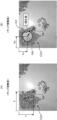
- Figures 7(A) and (B) are schematic diagrams showing the correction value acquisition process of step 3 executed by the correction value calculation unit 793.
- the correction value calculation unit 793 calculates a movement correction value for the head 61 from the difference between the target coordinate position and the actual coordinate position of the void portion EA.
- the target coordinate position PA (X, Y) set by the trace creation unit 792 is shown in the cell distribution area CDA in Figure 7(A). If there is no positional deviation of the tip 10T of the chip 10, the syringe tip 113 will come into contact with the target coordinate position PA.
- Figure 7 (B) shows a void EA that is actually formed in the cell distribution area CDA by providing the target coordinate position PA to the axis control unit 71 and operating the head 61 to press the tip of the tip 10 against it.
- the void EA has a size that corresponds to the outer diameter of the syringe tip 113.
- the correction value calculation unit 793 determines the center position of the void EA based on an image including the void EA, and treats this center position as the actual coordinate position PB. For example, a process can be applied in which the outline of the void EA is found by edge detection image processing, and the obtained outline is replaced with an approximate circle to determine the center position.
- the actual coordinate position PB (Xa, Ya) is misaligned with respect to the target coordinate position PA (X, Y).
- the correction value calculation unit 793 calculates the difference between the two coordinates, and uses this difference as the correction value for the XY movement of the head 61 in the XY plane.
- the correction value for the head 61 in the Z direction perpendicular to the XY plane is obtained based on the Z coordinate position where the tip 10 is pressed against the bottom surface 31, detected by the stepwise descent of the tip 10 performed in step 2. Such a correction value is calculated for each well 3 and for each type of tip 10.
- the correction value calculation unit 793 may refer to information relating to the tip shape of the chip 10 when identifying the void EA from an image including the void EA. As illustrated in FIG. 6B, if a cell distribution area CDA where many cells C are densely packed is present on the bottom surface 31 of the well 3, it is relatively easy to identify the void EA on the image. However, if only a cell distribution area CDA with low cell density is present on the bottom surface 31, it may be difficult to distinguish between the areas with low cell density and the void EA on the image.
- the memory unit 75 stores information related to the tip shape of the tip 10, such as the outer diameter, thickness, and opening diameter of the tip opening t of the syringe tip 113.
- the void portion EA formed by pressing the tip of the tip 10 is a trace that generally follows the tip shape of the tip 10. Therefore, by referring to the above information, it becomes easier to identify the void portion EA on the image. For example, the void portion EA can be detected by using a template corresponding to the tip portion 10T and performing a matching process on an image including the void portion EA.
- the trace creation unit 792 may be caused to press the tip of the chip 10 against the cell distribution area CDA, and then execute a trace-imparting process in which the chip 10 is moved horizontally in a predetermined direction. This trace-imparting process makes it possible to form a longitudinal void in the cell distribution area CDA.
- FIG. 8 shows an example of forming a longitudinal void EAa in the cell distribution area by horizontally moving the tip 10.
- the trace creating unit 792 lowers the head 61, for example, at 5 ⁇ m intervals, to bring the tip 10T into contact with the cell distribution area CDA.
- the trace creating unit 792 moves the head 61, for example, by about 50 ⁇ m in the X direction. This operation causes the contact trace of the tip 10T to extend in the X direction, forming a longitudinal void EAa in the X direction.
- a void EAa has the advantage that it is easier to identify on the image than a void formed by simply pressing the tip of the tip against it.
- the trace creation unit 792 acquires an image including the void EAa, and causes the image processing unit 74 to execute a process to obtain the contour of the void EAa. If the area of the void EAa is too small compared to the area of the tip 10T, for example, if it is less than 50%, the trace creation unit 792 lowers the head 61 by one pitch and then repeatedly moves it in the X direction. The same operation is repeated until the area of the void EAa reaches a predetermined size.
- the correction value calculation unit 793 treats the position corresponding to the start end SE of the tip 10 in the longitudinal gap EAa in the moving direction as the actual coordinate position PB.
- the tip 10 When the tip 10 is moved in a predetermined direction with the tip 10T in contact with the cell distribution area CDA or the bottom surface 31, the tip 10 bends as shown in FIG. 8. When bending occurs, a deviation occurs in the positional relationship between the axial center of the head 61 and the tip 10T of the tip 10. For this reason, an error occurs when the end of the tip 10 in the moving direction is taken as the actual coordinate position PB. Since the tip 10 is unlikely to bend at the start end SE, the inclusion of errors in the actual coordinate position PB can be suppressed.
- FIG. 9 is a diagram showing another example of setting the calibration area.
- Circular coating layers 32 (variable object areas) are provided at four locations near the outer periphery of the bottom surface 31 of the well 3.
- the coating layer 32 is a layer on which a trace may be formed by contact with the tip 10T of the chip 10. Examples of the coating layer 32 include an easily peelable ink coating layer and a coating layer of a gel-like material.
- the area setting unit 791 of the information processing unit 79 designates the coating layer 32 as the calibration area.
- the trace creating unit 792 presses the tip 10T of the tip 10 against the coating layer 32 to form a trace on the coating layer 32.
- the correction value calculating unit 793 identifies an actual coordinate position from the imprinted trace, and derives a correction value from the difference between the target coordinate position set for imprinting the trace and the actual coordinate position.
- the material forming the calibration area is not limited to the coating layer 32, and may be any variable object whose state can be changed by contact with the tip 10T of the tip 10.
- the calibration area may be formed of minute objects such as beads or powder.
- [Cell picking control flow] 10 is a flowchart showing the cell picking process.
- the main controller 78 receives a selection of a target cell Ct to be moved from the culture plate 2 to the destination plate 4 from the user via the input unit 76 (step S1). At the time of this selection, an image of the bottom surface 31 of the well 3, which is the cell culture surface, captured by the camera unit 5 is displayed on the display unit 77. The user identifies the target cell Ct while visually checking the display unit 77, and inputs the selection into the input unit 76.
- the information processing unit 79 acquires the address of the well 3 in which the selected target cell Ct exists (step S2). For example, when the above-mentioned 6-well plate is used as the culture plate 2, the well address previously assigned to the well is acquired in order to identify which of the 6 wells the target cell Ct exists in.
- the information processing unit 79 checks whether or not a correction process has been performed on the tip 10 currently attached to the head 61 for the well 3 at the acquired address (step S3).
- the correction process is a process for correcting the XYZ movement amount of the head 61 described above, taking into account the positional misalignment of the tip 10T of the tip 10 and the variation in height of the bottom surface 31 of the well 3, etc. If a correction value has already been acquired for the well 3 containing the target cell Ct, that is, if the correction value is stored in the memory unit 75 (YES in step S3), the information processing unit 79 corrects the coordinate position of the target cell Ct identified on the image with the correction value (step S4).
- the coordinate position after correction in step S4 becomes the coordinate position to which the head 61 is to be moved.
- the axis control unit 71 moves the head unit 6 in the XY directions so that the head 61 moves toward the coordinate position.
- the head control unit 72 lowers the head 61 (Z movement) and generates negative pressure at the tip opening t of the tip 10 to suck in the target cell Ct (step S5). Thereafter, the head unit 6 is moved to the destination plate 4.
- the information processing unit 79 executes a process to acquire the correction value (step S6).
- FIGS. 11 and 12 are flow charts showing the correction process.
- the information processing unit 79 acquires XYZ information, which is information on the XY position and height position for the well 3 at the address acquired in step S2, from the memory unit 75 (step S11).
- the area setting unit 791 sets the tip correction position, which is the calibration area where the tip 10 is to leave a trace, on the bottom surface 31 of the well 3 (step S12).
- the processing of step S12 corresponds to the processing of setting the tip correction positions TA1 to TA5 shown in FIG. 5.
- the main controller 78 causes the camera axis driver 53 to move the camera unit 5 in the XY direction and the imaging controller 73 to perform an imaging operation, thereby acquiring an image of the bottom surface 31 of the well 3 (step S13).
- the image processor 74 performs a predetermined image processing on the acquired image, and a recognition process of the cells C distributed on the bottom surface 31 is executed (step S14).
- a cell group that can leave a trace with the chip 10 for example, a cell distribution area CDA as exemplified in FIG. 5, has been recognized (step S15). If the cell distribution area CDA has not been recognized (NO in step S15), the main controller 78 causes the display unit 77 to display an error message and to display a message encouraging the addition of cells C to the well 3 (step S16).
- the trace creation unit 792 determines a trace position where a trace is to be left on the tip 10 (step S17).
- the trace position is set in an area where cells other than the target cell Ct gather in the tip correction position determined in step S12.
- the trace position is set in the cell distribution area CDA present in the tip correction position TA3, within the unused cell group surrounding the target cell Ct1.
- the trace creation unit 792 acquires the XY coordinate values of the trace position (step S18). These XY coordinate values correspond to the target coordinate position PA illustrated in FIG. 7, and are the XY coordinates to which the head 61 is moved in the operation of leaving the trace.
- the trace creation unit 792 further acquires the Z coordinate of the XY coordinate position (step S19).
- the trace creation unit 792 refers to the data on the height dimensional tolerance of the bottom surface 31 stored in the memory unit 75, and the mechanical error data of the head unit 6.
- the head 61 is moved in the XY direction, and after that movement, it is lowered (moved in the Z direction) (step S20).
- the camera unit 5 acquires an image of the bottom surface 31 of the well 3, and performs a recognition process of the cells C distributed on the bottom surface 31 based on the image (step S21).
- the trace creation unit 792 acquires the cell recognition result of step S21 (step S22), and performs a comparison process with the cell recognition result previously acquired in step S14 (step S23). As this comparison process, for example, an image subtraction process can be applied.
- step S20 If there is a difference between the two cell recognition results, the tip 10T of the tip 10 comes into contact with the cell distribution area CDA by lowering the head 61 in step S20, and a trace is left. If there is no difference between the two cell recognition results (NO in step S24), this means that a trace has not yet been left, so the head 61 is lowered so that the tip 10 is lowered by one pitch (e.g., 5 ⁇ m) (step S25). The process then returns to step S21 and is repeated. In other words, the height of the tip 10T is gradually lowered, and the degree of the trace is checked on the image.
- one pitch e.g., 5 ⁇ m
- the correction value calculation unit 793 identifies the location related to the difference, i.e., the trace caused by the contact of the tip 10, on the image as the void area EA illustrated in FIG. 7(B) (step S26). Furthermore, the correction value calculation unit 793 obtains the outline of the void area EA and calculates its center position to obtain the coordinates of the position where the tip 10T of the tip 10 actually contacts the cell distribution area CDA (step S27). The coordinates become the actual coordinate position PB shown in FIG. 7(B).
- the correction value calculation unit 793 derives an XY correction value for moving the head 61 by determining the difference between the actual coordinate position PB acquired in step S28 and the target coordinate position PA identified in step S18 (step S28). Furthermore, the correction value calculation unit 793 derives a Z correction value based on the Z height of the tip 10T when the contact mark of the tip 10 is confirmed (step S29). These XYZ correction values are stored in the memory unit 75 and are used during the correction in step S4 of FIG. 10.
- FIG. 13 is a flowchart showing a correction process according to a modified example, which is an example of changing the manner in which the head 61 is lowered depending on whether the Z coordinate of cell C has been accurately acquired.
- the flowchart in FIG. 13 shows a process that replaces step 19 in FIG. 11 to step S26 in FIG. 12.
- step S20 of the above embodiment an example is shown in which the head 61 is simply moved sequentially in the XY direction and the Z direction.
- the trace creation unit 792 determines whether the Z coordinate of cell C has been accurately acquired by the imaging so far (step S32).
- the trace creation unit 792 sets the predetermined facing height at which the descent of the head 61 is switched from high-speed descent to gradual descent to a height position obtained by adding the upper limit of the mechanical error of the head unit 6 to the Z coordinate of cell C. Then, the trace creation unit 792 controls the head drive unit 64 via the head control unit 72 to move the head 61 in the Z direction at high speed (high-speed descent) until the tip 10T of the tip 10 reaches the facing height (step S33).
- the trace creation unit 792 sets the facing height to a height position obtained by adding the upper limit of the height dimensional tolerance of the bottom surface 31 and the upper limit of the mechanical error of the head unit 6 to the provisionally acquired Z coordinate of cell C. Then, the trace creation unit 792 quickly lowers the head 61 until the tip 10T of the tip 10 reaches the facing height (step S34).
- the trace creation unit 792 sets the Z movement pitch of the head 61 after the facing height (step S35). For example, it sends an instruction signal to the head control unit 72 to gradually lower the head 61 at a pitch of several ⁇ m.
- the camera unit 5 captures an image of the cell distribution area CDA for each pitch of the downward movement of the head 61, and a process of confirming the pressing trace of the chip 10 is performed.
- the camera unit 5 acquires an image of the well 3, and a process of recognizing the cells C distributed on the bottom surface 31 is performed based on the image (step S36).
- the trace creation unit 792 acquires the cell recognition result of step S36 (step S37), and performs a comparison process with the cell recognition result previously acquired in step S14 (step S38). If there is no difference between the two cell recognition results (NO in step S39), the head 61 is lowered by one pitch (step S40). Then, the process returns to step S36 and is repeated.
- step S39 if a difference is confirmed between the two cell recognition results (YES in step S39), the process proceeds to step S26 in FIG. 12.
- step S32 the execution period of the loop of steps S36 to S40, which takes time, can be shortened.
- FIG. 14 (A) to (D) are diagrams for explaining the correction process according to the second embodiment of the present invention.
- the liquid medium LCM is poured into the well 3, and picking of a cell C that is cultured in contact with the bottom surface 31 is exemplified.
- the cells may be cultured in a gel-like medium GCM.
- the present invention can also be applied to the movement of cells in the gel-like medium GCM.
- a large number of cells including a target cell Cpa that is the target of suction in correction control and its surrounding cells Cn, are cultured in a gel culture medium GCM.
- the target cell Cpa and the surrounding cells Cn are spaced apart in the XY direction, and are also spaced apart in the Z direction.
- the area setting unit 791 of the information processing unit 79 sets a certain three-dimensional area in the gelatinous medium GCM as the calibration area.
- the calibration area includes the target cell Cpa and surrounding cells Cn.
- the trace creation unit 792 identifies the XYZ coordinates of the target cell Cpa from the camera image, and determines these coordinates as the target coordinate position to which the head 61 is moved. This target coordinate position is given to the axis control unit 71 and head control unit 72, and the head 61 is moved to the XY coordinates of the target coordinate position, while the tip 10T of the tip 10 is lowered to the Z coordinate of the target coordinate position. Then, the tip 10 is caused to perform a suction operation.
- Figure 14 (B) is an image of the gelatinous medium GCM in the calibration area after the suction operation has been performed. Even though the suction operation was performed aiming at the target cell Cpa, the target cell Cpa remains in the gelatinous medium GCM. On the other hand, it can be seen that the surrounding cell Cn has disappeared and instead been sucked into the chip 10. When a cell is sucked into the gelatinous medium GCM, the area where the cell temporarily existed becomes hollow, leaving a trace. That is, as shown in Figure 14 (C), after the surrounding cell Cn has been sucked in, a suction mark Cna remains.
- the correction value calculation unit 793 identifies the coordinate position of the suction mark Cna and treats this as the actual coordinate position. The correction value calculation unit 793 then determines the difference between the target coordinate position, which is the coordinate of the target cell Cpa to be suctioned, and the actual coordinate position, which is the coordinate of the suction mark Cna where suction was actually performed. Based on this difference, the XY correction value and Z correction value for moving the head 61 are obtained, as shown in FIG. 13(D).
- the present invention is not limited to the above embodiment, and various modifications are possible.
- the target coordinate position to which the head 61 moves to form a trace is set in the cell distribution area CDA.
- one cell or one bead
- the center of two or three adjacent cells may be set as the target coordinate position.
- a correction value for the position coordinate of the head 61 may be derived based on a trace of the shift of the one cell caused by the chip 10 coming into contact with the one cell.
- the position of the cell that the chip 10 eventually comes into contact with may be treated as the target coordinate position, and a correction value may be derived.
- FIGS 15(A) and (B) show desirable shapes of the tip of the tip 10.
- the tip 10T1 of Figure 15(A) has a shape in which the outer circumferential surface tapers toward the tip.
- the tip 10T2 of Figure 15(B) has a shape in which the diameter tapers in a stepped manner toward the tip.
- a target coordinate position is given to the driving unit of the head 61 to operate the head 61, and a trace is actually made with the tip 10 in the calibration area of the well 3 of the culture plate 2.
- the trace is then used to obtain a correction value for the coordinate position to which the head 61 is to be moved.
- the deviation between the target coordinate position PA and the actual coordinate position PB is found, and a correction value is derived. Therefore, even if there is variation in the height of the bottom surface 31 of the well 3 or a positional deviation of the tip 10T of the tip 10 attached to the head 61, an accurate correction value can be obtained. Therefore, small target cells Ct having a size of several ⁇ m to several tens of ⁇ m can be accurately picked.
- a cell movement device is a cell movement device that moves a specific target cell among cells contained in a first container to a second container, and includes a camera that captures images of the cells contained in the first container, a head that is equipped with a tip having a tip that aspirates and discharges cells, moves to the position of the target cell in the first container based on the image captured by the camera, aspirates the target cell into the tip, moves to the second container, and discharges the target cell in the tip into the second container, and an information processing unit that corrects the actual position coordinates of the head, and the information processing unit sets a calibration area in the first container and sets a predetermined location in the calibration area as a target coordinate position to which the head will move, operates the head so that the tip leaves a predetermined trace on the calibration area, causes the camera to capture an image of an area including the trace and identifies the actual coordinate position of the trace, and obtains a correction value for the position coordinates of the head by calculating the difference between the target coordinate position
- this cell movement device With this cell movement device, a target coordinate position is given and the head is operated, and a trace is actually made with the tip in the calibration area of the first container. The trace is then used to obtain a correction value for the coordinate position.
- a correction value is derived. Therefore, even if there is variation in the height of the culture surface of the first container or a positional misalignment of the tip attached to the head, an accurate correction value can be obtained. Therefore, small target cells measuring several ⁇ m to several tens of ⁇ m in size can be accurately picked.
- the information processing unit sets the calibration region to a cell distribution area in the first container where cells other than the target cells gather, and presses the tip of the tip against the cell distribution area as the trace to form a gap in the cell distribution area.
- a trace is formed by pressing the tip of the tip against an area where cells are distributed.
- the tip of the tip is pressed against an area where cells are distributed to a certain extent, the cells that were present in the pressed area are forced to escape to the periphery of the pressed area.
- the pressed area becomes a void area where there are no cells or where the number of cells is extremely small.
- Such voids are easily visible in a camera image.
- a trace that is easy to see on an image can be formed by the simple action of pressing the tip of the tip.
- the information processing unit can determine the center position of the gap based on an image including the gap, and treat the center position as the actual coordinate position.
- the gap formed by pressing the tip against the surface has a certain area. For this reason, it is desirable to identify any position of the gap as the actual coordinate position. According to the above aspect, the actual coordinate position can be identified by a rational and simple method of finding the center position of the gap.
- the information processing unit refer to information regarding the tip shape of the tip when identifying the void from an image that includes the void.
- the tip shape of the tip is referenced, making it easier to identify the voids formed by pressing the tip of the tip on the image.
- the information processing unit may press the tip of the tip against the cell distribution area and then move the tip in a predetermined direction to form a longitudinal gap in the cell distribution area in the predetermined direction.
- longitudinal voids can be formed in the cell distribution area by pressing the tip of the tip against the cell and then moving it.
- Such voids have the advantage that they are easier to identify on an image than voids formed by simply pressing the tip of the tip against the cell.
- the information processing unit prefferably treats the position corresponding to the start end of the tip's movement direction in the longitudinal gap as the actual coordinate position.
- the tip When the tip is moved in a specific direction, bending of the tip occurs, which can cause a misalignment in the positional relationship between the axial center of the head and the tip tip.
- the starting point of the tip's movement direction is treated as the actual coordinate position, so the effects of the bending can be eliminated.
- the tip of the tip is pressed against the cell distribution area by lowering the head, and it is preferable that the information processing unit lowers the head at a first speed until the tip of the tip is positioned at a predetermined opposing height, and after the predetermined height, lowers the head at a second speed that is equal to or lower than the first speed.
- the head is lowered at a first speed up to the opposing height, and then at a slower second speed. Therefore, it is possible to shorten the tact time of the process of leaving a mark by pressing the tip against the cell.
- the information processing unit lowers the head at a predetermined pitch after the predetermined height, and causes the camera to perform an image capture operation after each pitch of the descent.
- This aspect makes it possible to reliably capture the traces formed by the head tip pressing against the cell distribution area.
- the first container has a flat bottom surface, cells are positioned on top of the bottom surface, and when the height position of the cell has been accurately acquired, the information processing unit sets the opposing height to a height obtained by adding the mechanical error of the head to the height position of the cell, and when the height position of the cell has been provisionally acquired but the accuracy is unknown, set the opposing height to a height obtained by adding the height dimensional tolerance of the bottom surface of the first container and the mechanical error of the head to the provisionally acquired height position of the cell.
- the manner in which the head 61 descends is changed depending on whether the height position of the cell has been accurately obtained. This makes it possible to shorten the tact time of the process that leaves a trace, while reliably obtaining images before and after the tip hits the cell.
- the information processing unit may set the calibration region to a variable object area in the first container in which a variable object capable of changing its state upon contact with the chip is disposed, and may press the tip of the chip against the variable object area to form a trace in the variable object area as the trace.
- a trace can be formed by pressing the tip of the tip against the variable object area, making it possible to avoid pressing the tip of the tip against the cells in the first container.
- the information processing unit obtains correction values in the X and Y directions on the XY plane as correction values for the position coordinates of the head. It is further preferable that the information processing unit obtains a correction value in the Z direction perpendicular to the XY plane.
- the movement of the head can be accurately controlled in the XY plane. Furthermore, by acquiring a correction value in the Z direction, the three-dimensional movement of the head in the XYZ directions can be accurately controlled.
- the present invention provides a cell migration device that can accurately pick target cells.
Landscapes
- Life Sciences & Earth Sciences (AREA)
- Chemical & Material Sciences (AREA)
- Engineering & Computer Science (AREA)
- Bioinformatics & Cheminformatics (AREA)
- Health & Medical Sciences (AREA)
- Wood Science & Technology (AREA)
- Biotechnology (AREA)
- Organic Chemistry (AREA)
- Zoology (AREA)
- Microbiology (AREA)
- Sustainable Development (AREA)
- Biomedical Technology (AREA)
- Biochemistry (AREA)
- General Engineering & Computer Science (AREA)
- General Health & Medical Sciences (AREA)
- Genetics & Genomics (AREA)
- Medicinal Chemistry (AREA)
- Apparatus Associated With Microorganisms And Enzymes (AREA)
Priority Applications (1)
| Application Number | Priority Date | Filing Date | Title |
|---|---|---|---|
| JP2025537845A JPWO2025028303A1 (https=) | 2023-07-31 | 2024-07-19 |
Applications Claiming Priority (2)
| Application Number | Priority Date | Filing Date | Title |
|---|---|---|---|
| JP2023-124538 | 2023-07-31 | ||
| JP2023124538 | 2023-07-31 |
Publications (1)
| Publication Number | Publication Date |
|---|---|
| WO2025028303A1 true WO2025028303A1 (ja) | 2025-02-06 |
Family
ID=94395215
Family Applications (1)
| Application Number | Title | Priority Date | Filing Date |
|---|---|---|---|
| PCT/JP2024/025937 Pending WO2025028303A1 (ja) | 2023-07-31 | 2024-07-19 | 細胞移動装置 |
Country Status (2)
| Country | Link |
|---|---|
| JP (1) | JPWO2025028303A1 (https=) |
| WO (1) | WO2025028303A1 (https=) |
Citations (4)
| Publication number | Priority date | Publication date | Assignee | Title |
|---|---|---|---|---|
| JP2008092857A (ja) * | 2006-10-11 | 2008-04-24 | Olympus Corp | 細胞分離装置及び細胞分離方法 |
| JP2015056593A (ja) * | 2013-09-13 | 2015-03-23 | 株式会社日立ハイテクインスツルメンツ | ダイボンダ及び半導体製造方法 |
| JP6173331B2 (ja) | 2011-11-17 | 2017-08-02 | ビオメリューBiomerieux | サンプリング工具の変位を操縦する光学的方法 |
| WO2022145086A1 (ja) * | 2020-12-28 | 2022-07-07 | ヤマハ発動機株式会社 | 細胞移動装置 |
-
2024
- 2024-07-19 WO PCT/JP2024/025937 patent/WO2025028303A1/ja active Pending
- 2024-07-19 JP JP2025537845A patent/JPWO2025028303A1/ja active Pending
Patent Citations (4)
| Publication number | Priority date | Publication date | Assignee | Title |
|---|---|---|---|---|
| JP2008092857A (ja) * | 2006-10-11 | 2008-04-24 | Olympus Corp | 細胞分離装置及び細胞分離方法 |
| JP6173331B2 (ja) | 2011-11-17 | 2017-08-02 | ビオメリューBiomerieux | サンプリング工具の変位を操縦する光学的方法 |
| JP2015056593A (ja) * | 2013-09-13 | 2015-03-23 | 株式会社日立ハイテクインスツルメンツ | ダイボンダ及び半導体製造方法 |
| WO2022145086A1 (ja) * | 2020-12-28 | 2022-07-07 | ヤマハ発動機株式会社 | 細胞移動装置 |
Also Published As
| Publication number | Publication date |
|---|---|
| JPWO2025028303A1 (https=) | 2025-02-06 |
Similar Documents
| Publication | Publication Date | Title |
|---|---|---|
| CN110763752B (zh) | 单细胞萃取电喷雾质谱分析系统和方法 | |
| US7667890B2 (en) | Cytological imaging systems and methods | |
| US12123888B2 (en) | Apparatus and method for picking biological sample | |
| CN106525622B (zh) | 硬度测试设备和硬度测试方法 | |
| CN101799417B (zh) | 生物芯片的扫描方法以及实施该扫描方法的装置 | |
| US11525995B2 (en) | Imaging system | |
| JP5826250B2 (ja) | マイクロ操作ツールを無衝突で位置決めする方法 | |
| JP7283846B2 (ja) | 生体試料を採取するための装置及び方法 | |
| WO2017110005A1 (ja) | 対象物のピックアップ方法 | |
| JP4831972B2 (ja) | マイクロマニピュレーションシステム | |
| JP6913184B2 (ja) | 生体対象物処理装置 | |
| JPWO2019163270A1 (ja) | 生体対象物のピックアップ装置 | |
| JP2021184769A (ja) | 細胞吸引支援装置および細胞吸引支援装置の制御方法 | |
| CN112322713B (zh) | 成像方法、装置及系统及存储介质 | |
| JP7525657B2 (ja) | 細胞移動装置 | |
| WO2025028303A1 (ja) | 細胞移動装置 | |
| JP5315429B2 (ja) | 動的接触角計および動的接触角の測定方法 | |
| CN113237425B (zh) | 单摄像头辅助坐标测量机测量微小工件的自动引导方法 | |
| WO2018074086A1 (ja) | 細胞移動装置 | |
| JP5120055B2 (ja) | 微小物体回収装置および微小物体回収方法 | |
| CN118275714A (zh) | 在自动样本处置设备中精确定位机械臂的方法和设备 | |
| CN111699243B (zh) | 摄像系统以及生物对象物移动装置 | |
| JP2023019080A (ja) | 観察システム、プログラム、及び観察方法 | |
| JP2003149094A (ja) | スポッティング装置 | |
| WO2025037480A1 (ja) | 細胞移動装置および方法 |
Legal Events
| Date | Code | Title | Description |
|---|---|---|---|
| 121 | Ep: the epo has been informed by wipo that ep was designated in this application |
Ref document number: 24848958 Country of ref document: EP Kind code of ref document: A1 |
|
| ENP | Entry into the national phase |
Ref document number: 2025537845 Country of ref document: JP Kind code of ref document: A |
|
| WWE | Wipo information: entry into national phase |
Ref document number: 2025537845 Country of ref document: JP |
|
| WWE | Wipo information: entry into national phase |
Ref document number: 2024848958 Country of ref document: EP |
|
| NENP | Non-entry into the national phase |
Ref country code: DE |