WO2025028186A1 - カテーテル - Google Patents
カテーテル Download PDFInfo
- Publication number
- WO2025028186A1 WO2025028186A1 PCT/JP2024/024770 JP2024024770W WO2025028186A1 WO 2025028186 A1 WO2025028186 A1 WO 2025028186A1 JP 2024024770 W JP2024024770 W JP 2024024770W WO 2025028186 A1 WO2025028186 A1 WO 2025028186A1
- Authority
- WO
- WIPO (PCT)
- Prior art keywords
- region
- tubular member
- longitudinal direction
- catheter
- outer edge
- Prior art date
- Legal status (The legal status is an assumption and is not a legal conclusion. Google has not performed a legal analysis and makes no representation as to the accuracy of the status listed.)
- Pending
Links
Images






Classifications
-
- A—HUMAN NECESSITIES
- A61—MEDICAL OR VETERINARY SCIENCE; HYGIENE
- A61M—DEVICES FOR INTRODUCING MEDIA INTO, OR ONTO, THE BODY; DEVICES FOR TRANSDUCING BODY MEDIA OR FOR TAKING MEDIA FROM THE BODY; DEVICES FOR PRODUCING OR ENDING SLEEP OR STUPOR
- A61M25/00—Catheters; Hollow probes
-
- A—HUMAN NECESSITIES
- A61—MEDICAL OR VETERINARY SCIENCE; HYGIENE
- A61M—DEVICES FOR INTRODUCING MEDIA INTO, OR ONTO, THE BODY; DEVICES FOR TRANSDUCING BODY MEDIA OR FOR TAKING MEDIA FROM THE BODY; DEVICES FOR PRODUCING OR ENDING SLEEP OR STUPOR
- A61M25/00—Catheters; Hollow probes
- A61M25/0021—Catheters; Hollow probes characterised by the form of the tubing
-
- A—HUMAN NECESSITIES
- A61—MEDICAL OR VETERINARY SCIENCE; HYGIENE
- A61M—DEVICES FOR INTRODUCING MEDIA INTO, OR ONTO, THE BODY; DEVICES FOR TRANSDUCING BODY MEDIA OR FOR TAKING MEDIA FROM THE BODY; DEVICES FOR PRODUCING OR ENDING SLEEP OR STUPOR
- A61M25/00—Catheters; Hollow probes
- A61M25/01—Introducing, guiding, advancing, emplacing or holding catheters
Definitions
- the present invention relates to a catheter.
- Patent Document 1 discloses such a catheter, which includes a first tubular member that extends in the longitudinal direction, has a distal end and a proximal end, and into which a wire is inserted, and a second tubular member that has a distal end and a proximal end and is adjacent to the first tubular member in the radial direction, the distal end of the first tubular member being located proximal to the distal end of the second tubular member, the proximal end of the first tubular member being located proximal to the proximal end of the second tubular member, the first tubular member having a reinforcing part having an inner layer containing at least one selected from the group consisting of polytetrafluoroethylene and tetrafluoroethylene-perfluoroalkylvinylether copolymer and a reinforcing member, and the first tubular member having a reinforcing part having an inner layer containing at least one selected from the group consisting of polytetra
- Patent Document 1 Conventional catheters such as those described in Patent Document 1 can be difficult to insert into blood vessels that have continuous three-dimensional meanderings, such as coronary arteries.
- the present invention was made in consideration of the above circumstances, and its purpose is to provide a catheter that is easy to insert into meandering parts of the body.
- a catheter according to an embodiment of the present invention that can solve the above problems is as follows.
- a first tubular member extending in a longitudinal direction; a second cylindrical member extending in the longitudinal direction and adjacent to the first cylindrical member in a radial direction; an outer member extending in the longitudinal direction and having a portion that contains at least a portion of the first tubular member and at least a portion of the second tubular member, a distal end of the first tubular member is located proximal to a distal end of the second tubular member; a proximal end of the first tubular member is located proximal to a proximal end of the second tubular member;
- the catheter has an outer member having a first region extending in the longitudinal direction distal to the proximal end of the second tubular member, and a second region extending in the longitudinal direction and located distal to the first region, wherein a ratio of the major axis to the minor axis in the radial cross section of the first region is 1.0 to 1.1
- the inventor's research has revealed that a catheter with a circular radial cross-sectional shape, such as that of Patent Document 1, is difficult to bend along the shape of a meandering section where three-dimensional meandering continues, such as in a coronary artery. Furthermore, the inventor's research has revealed that if the radial cross-sectional shape is elliptical, the catheter will be easier to bend along the shape of the meandering section, but will be harder to push in.
- the catheter will be easier to bend along the shape of the meandering section and easier to push in. This makes it easier to insert the catheter into a meandering section inside the body.
- the catheter according to the embodiment is preferably any one of the following [2] to [22].
- the shape of the outer edge of the first region in the radial cross section is a circle or an ellipse
- the catheter according to claim 1, wherein the shape of the outer edge of the second region in the radial cross section is an ellipse or a part of an ellipse.
- the outer member is tubular and has an inner cavity extending in the longitudinal direction, and at least a portion of the first tubular member and at least a portion of the second tubular member are disposed in the inner cavity.
- the outer member has a columnar body extending in the longitudinal direction and containing a resin, The catheter according to any one of [1] to [11], wherein at least a portion of the first tubular member and at least a portion of the second tubular member are disposed within the cylindrical body. [14] further comprising an outer tubular member extending in the longitudinal direction, The catheter according to any one of [1] to [13], wherein the outer tubular member has an inner cavity extending in the longitudinal direction, and a portion of the first tubular member is disposed in the inner cavity. [15] A catheter as described in [14], wherein the outer tubular member is located proximal to the proximal end of the second tubular member.
- a catheter described in [16] or [17] wherein the length of the fourth region in the longitudinal direction is longer than the sum of the length of the first region in the longitudinal direction and the length of the second region in the longitudinal direction.
- the present invention provides a catheter with the above configuration that is easy to insert into tortuous areas inside the body.
- FIG. 1 is a side view of a catheter according to a first embodiment.
- FIG. 2 is a longitudinal cross-sectional view of region R1 in FIG.
- FIG. 3 is a longitudinal cross-sectional view of region R2 in FIG.
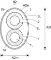
- FIG. 4 is a cross-sectional view of the catheter of FIG. 1 taken along line AA.
- FIG. 5 is a cross-sectional view of the catheter of FIG. 1 taken along line BB.
- FIG. 6 is a cross-sectional view of the catheter of FIG. 1 taken along the line CC.
- FIG. 7 is a cross-sectional view of the catheter of FIG. 1 taken along line DD.
- FIG. 8 is a cross-sectional view of the catheter of FIG. 1 taken along line EE.
- FIG. 1 is a side view of a catheter according to a first embodiment.
- FIG. 2 is a longitudinal cross-sectional view of region R1 in FIG.
- FIG. 3 is a longitudinal cross-sectional view of region R2 in FIG
- FIG. 9 is a longitudinal cross-sectional view of region R2 in a modification of the catheter of FIG.
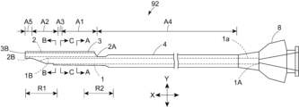
- FIG. 10 is a side view of the catheter according to the second embodiment.
- FIG. 11 is a longitudinal cross-sectional view of region R1 in FIG.
- FIG. 12 is a longitudinal cross-sectional view of region R2 in FIG.
- FIG. 13 is a cross-sectional view of the catheter of FIG. 10 taken along line AA.
- FIG. 14 is a cross-sectional view of the catheter of FIG. 10 taken along line BB.
- FIG. 15 is a cross-sectional view of the catheter of FIG. 10 taken along the line CC.
- FIG. 16 is a cross-sectional view of a variation of the catheter of FIG.
- the catheter according to the embodiment has a first tubular member extending in the longitudinal direction, a second tubular member extending in the longitudinal direction and adjacent to the first tubular member in the radial direction, and an outer member extending in the longitudinal direction and having a portion containing at least a part of the first tubular member and at least a part of the second tubular member, the distal end of the first tubular member being located proximal to the distal end of the second tubular member, the proximal end of the first tubular member being located proximal to the proximal end of the second tubular member, the outer member having a first region extending in the longitudinal direction distal to the proximal end of the second tubular member, and a second region extending in the longitudinal direction and located distal to the first region, the ratio of the major axis to the minor axis in the radial cross section of the first region being 1.0 to 1.1, and the ratio of the major axis to the minor axis in the radial cross section of the
- the inventors' investigations have revealed that a catheter with a circular radial cross-sectional shape is difficult to bend along the shape of a meandering section where three-dimensional meandering continues, such as in a coronary artery.
- the inventors' investigations have also revealed that if the radial cross-sectional shape is elliptical, the catheter will be easier to bend along the shape of the meandering section, but will be harder to push in.
- the inventors' investigations have further revealed that by positioning the second region, where the major axis/minor axis value in the radial cross-section is 1.2 to 2.0, more distally than the first region, where the major axis/minor axis value is 1.0 to 1.1, the catheter will be easier to bend along the shape of the meandering section and easier to push in. This makes it easier to insert the catheter into a meandering section inside the body.
- Fig. 1 is a side view of a catheter according to a first embodiment.
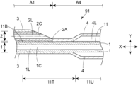
- Fig. 2 is a longitudinal cross-sectional view of region R1 in Fig. 1.
- Fig. 3 is a longitudinal cross-sectional view of region R2 in Fig. 1.
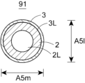
- Fig. 4 is a cross-sectional view A-A of the catheter in Fig. 1.
- Fig. 5 is a cross-sectional view B-B of the catheter in Fig. 1.
- Fig. 6 is a cross-sectional view C-C of the catheter in Fig. 1.
- Fig. 7 is a cross-sectional view D-D of the catheter in Fig. 1.
- Fig. 1 is a side view of a catheter according to a first embodiment.
- Fig. 2 is a longitudinal cross-sectional view of region R1 in Fig. 1.
- Fig. 3 is a longitudinal cross-sectional view of region R2 in Fig. 1.
- Fig. 4 is a cross-sectional view A-
- FIG. 8 is a cross-sectional view E-E of the catheter in Fig. 1.
- Fig. 9 is a longitudinal cross-sectional view of region R2 in a modified version of the catheter in Fig. 1.
- Fig. 16 is a cross-sectional view of a modified version of the catheter in Fig. 5.
- the catheter according to the first embodiment is a catheter 91 having a first tubular member 1 extending in the longitudinal direction X and a second tubular member 2 extending in the longitudinal direction X and adjacent to the first tubular member 1 in the radial direction Y.
- the outer surface of the first tubular member 1 and the outer surface of the second tubular member 2 are adjacent to each other in the radial direction Y.
- the first tubular member 1 has an inner lumen 1L extending in the longitudinal direction X.
- the second tubular member 2 has an inner lumen 2L extending in the longitudinal direction X.
- the catheter 91 By inserting, for example, a guide wire into each of the inner lumen 1L and the inner lumen 2L, the catheter 91 can be guided in multiple directions, making it easier to insert the catheter 91 into various branching parts of the coronary artery, for example. In addition, it is easier to search for the entrance of a stenosis, which is a lesion, by inserting a search wire into the inner lumen 1L or the inner lumen 2L. Of these, it is preferable to insert a probing wire into the lumen 1L. The tip of the probing wire may be bent.
- the first tubular member 1 and the second tubular member 2 each preferably have one or more layers extending in the longitudinal direction X, and more preferably have multiple layers.
- the multiple layers preferably have an inner layer and an outer layer that contains at least a part of the inner layer.
- the multiple layers may further have an intermediate layer located between the inner layer and the outer layer.
- the number of intermediate layers is not limited to one, and may be two or more. It is preferable that each of the multiple layers contains a material different from that of the adjacent layer.
- the inner layer of the first tubular member 1 and the inner layer of the second tubular member 2 each preferably contain at least one resin selected from the group consisting of polyolefin resins and fluorine-based resins.
- the polyolefin resin is preferably polyethylene, polypropylene, an ethylene-propylene copolymer, or a mixture thereof.
- the polyethylene is preferably high-density polyethylene with a specific gravity of 0.942 or more.
- the fluororesin is preferably polytetrafluoroethylene, tetrafluoroethylene-perfluoroalkylvinylether copolymer, tetrafluoroethylene-hexafluoropropylene copolymer, tetrafluoroethylene-ethylene copolymer, polyvinylidene fluoride, polychlorotrifluoroethylene, ethylene-chlorotrifluoroethylene copolymer, or a mixture thereof.
- the inner layer of the first cylindrical member 1 and the inner layer of the second cylindrical member 2 may each contain at least one selected from the group consisting of polyamide resin, polyester resin, polyurethane resin, polyolefin resin, fluorine resin, vinyl chloride resin, silicone resin, and natural rubber.
- the inner layer of the first cylindrical member 1 and the inner layer of the second cylindrical member 2 may contain different resins, preferably the same resin, and more preferably the same resin.
- the outer layer of the first tubular member 1 and the outer layer of the second tubular member 2 each preferably contain a flexible resin.
- the outer layers contain a flexible resin, which makes it easier for the catheter 91 to bend.
- the flexible resin preferably contains at least one type selected from the group consisting of polyethylene, polyurethane, polyurethane-based thermoplastic elastomer, styrene-based thermoplastic elastomer, polyamide elastomer, and polyamide, and more preferably contains at least one type selected from the group consisting of polyurethane and polyamide elastomer.
- the polyethylene is preferably a low-density polyethylene with a specific gravity of 0.91 to 0.92.
- the Shore D hardness of the material of the outer layer is preferably smaller than or equal to the Shore D hardness of the material of the inner layer, and is preferably smaller. This makes the catheter 91 easier to bend.
- the Shore D hardness may be measured, for example, using a durometer type D in accordance with ISO 7619.
- the intermediate layer preferably contains a different material than the inner or outer layer, but may contain the same material as the inner or outer layer.
- the inner layer, middle layer, and outer layer are preferably fixed to the adjacent layers. This makes it difficult for each layer to twist or kink. Examples of the manner of fixing include welding and adhesion. Although not shown, a reinforcing member may be disposed as the middle layer.
- the first tubular member 1 is preferably provided with a reinforcing member. This makes it easier to prevent the wire from breaking through the first tubular member 1.
- the second tubular member 2 is preferably not provided with a reinforcing member. This makes it easier to improve the flexibility of the second tubular member 2.
- the reinforcing member is preferably a braided body in which wire is braided, a coil body in which wire is wound in a spiral shape, or a combination of these. This makes it easier to prevent the wire from breaking through the first tubular member 1. Of these, the braided body is more preferable because it is easier to improve the rigidity.
- wires contained in the reinforcing member include metal wires and fibers.
- the metal wire preferably contains stainless steel, titanium, nickel-titanium alloy, cobalt-chromium alloy, tungsten alloy, or an alloy thereof. Of these, stainless steel is more preferable.
- the metal wire may be a single wire or a twisted wire.
- the distal end of the reinforcing member is preferably located closer to the proximal end of the first opening 1E and more preferably closer to the proximal end 2A of the second tubular member 2.
- the proximal end of the reinforcing member is preferably located closer to the proximal end 2A of the second tubular member 2, and more preferably located within the handle portion 8. This makes it easier to prevent the wire from breaking through the first tubular member 1.
- the distal end 1B of the first tubular member 1 is located proximal to the distal end 2B of the second tubular member 2. This makes it easier for the catheter 91 to bend in the portion distal to the distal end 1B of the first tubular member 1.
- the proximal end 1A of the first tubular member 1 is located proximal to the proximal end 2A of the second tubular member 2.
- the catheter 91 has an outer member 3 that extends in the longitudinal direction X and has a portion that contains at least a portion of the first tubular member 1 and at least a portion of the second tubular member 2.
- the outer member 3 can protect the first tubular member 1 and the second tubular member 2, and can also make it easier to prevent the wire from breaking through from inside the catheter 91.
- the outer member 3 preferably contains at least one selected from the group consisting of polyethylene, polyurethane, polyurethane-based thermoplastic elastomer, styrene-based thermoplastic elastomer, polyamide elastomer, and polyamide. Of these, at least one selected from the group consisting of polyurethane and polyamide elastomer is more preferable.
- the outer member 3 has a first region A1 extending in the longitudinal direction X distally from the proximal end 2A of the second tubular member 2, and a second region A2 extending in the longitudinal direction X and located distally of the first region A1.
- the ratio of the major axis A1l to the minor axis A1m in the cross section of the first region A1 in the radial direction Y is 1.0 to 1.1.
- the ratio of the major axis A2l to the minor axis A2m in the cross section of the second region A2 in the radial direction Y is 1.2 to 2.0.
- the catheter 91 Since the major axis A1l/minor axis A1m value of the first region A1 is 1.0 to 1.1, the catheter 91 is less likely to twist in meandering parts of the body, making it easier to transmit forces from the proximal side to the distal side. On the other hand, by setting the value of the major axis A2l/minor axis A2m of the second region A2 distal to the first region A1 to 1.2 to 2.0, the catheter 91 can be easily curved along the shape of the meandering part in the body.
- the value of the major axis A2l/minor axis A2m is preferably 1.2 to 1.9, more preferably 1.2 to 1.7, and even more preferably 1.2 to 1.5.
- the outer member 3 only needs to have the first region A1 distal to the proximal end 2A of the second cylindrical member 2, and the first region A1 may be located distal to the proximal end 2A of the second cylindrical member 2.
- the length of the major axis A1l of the first region A1 is preferably 0.5 mm or more and 2.0 mm or less, and more preferably 0.7 mm or more and 1.6 mm or less.
- the major axis of each region in the radial Y cross section refers to the length of the longest line segment that connects two points on the outer edge of each region in the radial Y cross section and passes through the centroid. If the cross section is a part of an ellipse, as described below, the major axis of the circumscribing imaginary ellipse is the major axis in the radial Y cross section.
- the minor axis of each region in the radial Y cross section refers to the length of the shortest line segment that connects two points on the outer edge of each region in the radial Y cross section and passes through the centroid.
- the minor axis of the circumscribing imaginary ellipse is the minor axis in the radial Y cross section. If the outer edge of the radial Y cross section is a circle, the major and minor axes are the same length.
- the shape of the outer edge A1e in the cross section in the radial direction Y of the first region A1 is preferably a circle or an ellipse, and more preferably a circle. This makes it difficult for the first region A1 to twist in meandering parts inside the body, making it easier for the catheter 91 to transmit force from the proximal side to the distal side.
- the shape of the outer edge A1e in the cross section in the radial direction Y of the first region A1 may be a rounded polygon or the like.
- the first region A1 may have parts whose cross-sectional shapes in the radial direction Y are different from each other.
- the shape of the outer edge A2e in the cross section in the radial direction Y of the second region A2 is preferably an ellipse. This allows the second region A2 to bend easily along the shape of the meandering part inside the body, and the catheter 91 to bend easily along the shape of the meandering part inside the body.
- the shape of the outer edge A2e in the cross section in the radial direction Y of the second region A2 is preferably a partial ellipse.
- the partial ellipse shape is the shape after a part of the ellipse is cut out.
- the shape of the outer edge A2e in the cross section in the radial direction Y of the second region A2 may be a rounded polygon or the like.
- the second region A2 may have parts whose cross-sectional shapes in the radial direction Y are different from each other.
- the area of the region surrounded by the outer edge A1e in the radial Y cross section of the first region A1 is preferably larger than or equal to the area of the region surrounded by the outer edge A2e in the radial Y cross section of the second region A2, and more preferably larger. This makes it easier to insert the catheter 91 into a tortuous portion of the body.
- the area of the region surrounded by the outer edge A1e in the radial Y cross section of the first region A1 is preferably 1.00 times or more and 2.00 times or less, and more preferably 1.01 times or more and 1.50 times or less, of the area of the region surrounded by the outer edge A2e in the radial Y cross section of the second region A2.
- the major axis A2l of the second region A2 is preferably larger than or equal to the major axis A1l of the first region A1, and more preferably larger than the major axis A1l of the first region A1. This makes it easier for the second region A2 to transmit force from the proximal side to the distal side.
- the major axis A2l of the second region A2 may be smaller than the major axis A1l of the first region A1. In this case, the flexibility of the second region A2 is improved.
- the shortest distance in the radial direction Y from the outer edge A2e of the second region A2 of the outer member 3 to the outer edge 1e of the first tubular member 1 is preferably longer than or equal to the shortest distance from the outer edge A1e of the first region A1 of the outer member 3 to the outer edge 1e of the first tubular member 1, and more preferably longer than the shortest distance from the outer edge A1e to the outer edge 1e.
- the shortest distance in the second region A2 is measured in a portion of the second region A2 whose cross-sectional shape in the radial direction Y is an ellipse. The same applies to the shortest distance in the second region A2 below.
- the shortest distance from the outer edge A2e of the second region A2 of the outer member 3 to the outer edge 1e of the first tubular member 1 may be shorter than the shortest distance from the outer edge A1e of the first region A1 of the outer member 3 to the outer edge 1e of the first tubular member 1.
- the second region A2 in the vicinity of the first tubular member 1 is less likely to twist when inserted into the serpentine portion.
- the shortest distance from the outer edge A2e of the second region A2 of the outer member 3 to the outer edge 2e of the second tubular member 2 is preferably longer than or equal to the shortest distance from the outer edge A1e of the first region A1 of the outer member 3 to the outer edge 2e of the second tubular member 2, and more preferably longer than the shortest distance from the outer edge A1e to the outer edge 2e.
- the shortest distance in the second region A2 is measured in a portion of the second region A2 whose cross-sectional shape in the radial direction Y is an ellipse. The same applies to the shortest distance in the second region A2 below.
- the shortest distance from the outer edge A2e of the second region A2 of the outer member 3 to the outer edge 2e of the second tubular member 2 may be shorter than the shortest distance from the outer edge A1e of the first region A1 of the outer member 3 to the outer edge 2e of the second tubular member 2.
- the second region A2 in the vicinity of the second tubular member 2 is less likely to twist when inserted into the serpentine portion.
- the length of the second region A2 in the longitudinal direction X is shorter than the length of the first region A1 in the longitudinal direction X. This makes it easier to insert the catheter 91 into a tortuous portion of the body.
- the length of the first region A1 in the longitudinal direction X is 1.1 times or more and 30 times or less, and more preferably 1.2 times or more and 20 times or less, of the length of the second region A2 in the longitudinal direction X.
- the outer member 3 has a third region A3 between the first region A1 and the second region A2 in the longitudinal direction X, and it is preferable that the ratio of the major axis A3l to the minor axis A3m in the cross section of the third region A3 in the radial direction Y is greater than 1.1 and less than 1.2.
- the third region A3 makes it easier to avoid bending due to a sudden change in shape between the first region A1 and the second region A2. Therefore, it is more preferable that the first region A1 and the third region A3 are adjacent to each other in the longitudinal direction X, and that the third region A3 and the second region A2 are adjacent to each other in the longitudinal direction X.
- the length of the third region A3 in the longitudinal direction X is preferably 1 mm or more and 20 mm or less, and more preferably 3 mm or more and 10 mm or less.
- the value of major axis A3l/minor axis A3m of the third region A3 decreases from the proximal side to the distal side. This makes it easier to avoid bending due to the sudden change in shape between the first region A1 and the second region A2. It is preferable that the shape of the outer edge A3e of the third region A3 in the cross section in the radial direction Y is elliptical. This makes it easier to achieve the above-mentioned effects.
- the shape of the outer edge A3e of the third region A3 in the cross section in the radial direction Y may be a rounded polygon or the like.
- the distal end 3B of the outer member 3 is located distal to the distal end 2B of the second tubular member 2.
- At least a portion of the inner surface of the outer member 3 is fixed to the outer surfaces of the first tubular member 1 and the second tubular member 2. This makes it difficult for the outer member 3 to twist or twist. Examples of the manner of fixing include welding, adhesion, etc.
- the length in the longitudinal direction X from the distal end 3B of the outer member 3 to the distal end 2B of the second tubular member 2 is preferably greater than the maximum thickness of the second tubular member 2. This improves the flexibility of the catheter 91 near its distal end.
- the outer surfaces of the first tubular member 1 and the second tubular member 2 may not be in contact with each other, or may be in contact with each other and fixed.
- Examples of the fixing method include welding, adhesion, etc.
- the outer surface of the first tubular member 1 and the outer surface of the second tubular member 2 are not in contact with each other, they are preferably fixed to each other via the resin of the outer member 3.
- the shapes of the first lumen 1L and the second lumen 2L are preferably circular, elliptical, arched, or a combination of these, and more preferably circular or elliptical.
- the catheter 91 it is preferable that the first lumen 1L and the second lumen 2L are not connected to each other. In the cross section of the radial direction Y, the first lumen 1L may have a larger area than the second lumen 2L, may have a smaller area than the second lumen 2L, or may have the same area as the second lumen 2L.
- the first tubular member 1 preferably has a first opening 1E that communicates with the inner cavity 1L.
- the first opening 1E can be used as an entrance or exit for the wire.
- the second tubular member 2 preferably has a second opening 2E that communicates with the inner cavity 2L.
- the second opening 2E can be used as an entrance or exit for the wire.
- the outer member 3 preferably has a protuberance 34 that protrudes away from the central axis 2C on the side closer to the first tubular member 1 in the radial direction Y than the distal end 1B of the first tubular member 1. This allows the tip of the wire inserted into the first tubular member 1 to be guided in a different direction from the tip of the wire inserted into the second tubular member 2, making it easier to treat bifurcation lesions, etc. This also makes it harder for the wires to become entangled.
- the protuberance 34 is preferably adjacent to the distal end 1B of the first tubular member 1. This makes it easier to guide the wire coming out of the first opening 1E by the protuberance 34.
- the protuberance 34 has a first inclined portion inclined in a direction away from the central axis 2C as it approaches the distal side, and a second inclined portion inclined so as to approach the central axis 2C as it approaches the distal side. It is preferable that the second inclined portion is located more distal than the first inclined portion. The first inclined portion makes it easier to guide the wire coming out of the first opening 1E. The second inclined portion makes it easier to insert into the body.
- the shape of the outer surface of the first inclined portion and the second inclined portion in the cross section X is preferably linear or curved, and more preferably linear.
- the shape of the second inclined portion in the cross section X is linear, the shape of the second inclined portion is a so-called tapered shape.
- the second tubular member 2 may not have a protruding portion that protrudes away from the central axis 2C on the side distal to the distal end 1B of the first tubular member 1 and closer to the first tubular member 1 in the radial direction Y. This reduces the outer diameter of the catheter 91 by the amount of the protruding portion, making it easier for the catheter 91 to bend.
- the outer diameters of the first tubular member 1 and the second tubular member 2 are preferably 0.2 mm or more and 0.8 mm or less, and more preferably 0.3 mm or more and 0.7 mm or less. This makes it easier to insert the catheter 91 into the tortuous portion of the coronary artery.
- a handle portion 8 is preferably disposed at the proximal end 1a of the first tubular member 1.
- the proximal end 1a of the first tubular member 1 is preferably disposed within the handle portion 8.
- the practitioner can insert the catheter 91 into the body by grasping and pushing the handle portion 8.
- the outer shape of the handle portion 8 may be such that the practitioner can grasp it with his/her fingers.
- the handle portion 8 is preferably a resin molded product obtained by injection molding or the like. Examples of resins include polyolefin resins such as polyethylene and polypropylene, polycarbonate resins, and (meth)acrylic resins. Of these resins, transparent resins such as polycarbonate and polymethyl methacrylate are preferred. This makes it easier to see inside the handle portion 8, making it easier to insert the wire.
- the proximal end 1A of the first tubular member 1 is preferably located within the handle portion 8. This improves pushability.
- the handle portion 8 preferably has an inner cavity that communicates with the inner cavity 1L of the first tubular member 1 and extends in the longitudinal direction X, and a wire can be inserted through this inner cavity.
- the catheter 91 preferably further has an outer tubular member 4 extending in the longitudinal direction X.
- the outer tubular member 4 preferably has an inner cavity 4L extending in the longitudinal direction X, and a part of the first tubular member 1 is preferably disposed in the inner cavity 4L.
- the outer tubular member 4 can form a double tube structure (coaxial structure), which can improve the transmission of the pushing force while protecting the first tubular member 1.
- the outer tubular member 4 preferably has a fixed part fixed to the first tubular member 1 at the distal end and a non-fixed part not fixed to the first tubular member 1 on the proximal side of the fixed part. The non-fixed part can make it easier to release the force associated with the insertion of the wire into the first tubular member 1.
- the non-fixed part is longer than the fixed part in the longitudinal direction X. This can reduce the risk of the wire breaking through the first tubular member 1.
- the outer tubular member 4 preferably has a fixed part fixed to the handle part 8 at the proximal end.
- the outer tubular member 4 is preferably located proximal to the proximal end 2A of the second tubular member 2. This allows the outer diameter of the outer tubular member 4 to be reduced.
- the outer tubular member 4 preferably contains the same resin as the outer member 3 or a harder resin, and more preferably is made of a harder resin. A harder resin can improve pushability.
- the distal end of the outer tubular member 4 and the proximal end of the outer member 3 are preferably fixed to each other.
- the outer tubular member 4 has a fourth region A4 extending in the longitudinal direction X from the proximal end 2A of the second tubular member 2 to the proximal side, and the ratio of the major axis A4l to the minor axis A4m in the cross section of the fourth region A4 in the radial direction Y is preferably 1.0 to 1.1.
- major axis A4l/minor axis A4m be 1.0 to 1.1, the catheter 91 is less likely to twist in meandering parts of the body, making it easier to transmit force from the proximal side to the distal side.
- the outer tubular member 4 may have a fourth region A4 proximal to the proximal end 2A of the second tubular member 2, and the fourth region A4 may be located proximal to the proximal end 2A of the second tubular member 2.
- the major axis A2l of the second region A2 is smaller than the major axis A4l of the fourth region A4. This makes it easier for the second region A2 to bend in meandering areas within the body. It is preferable that the major axis A2l is 0.99 times or less, and more preferably 0.98 times or less, of the major axis A4l. On the other hand, it is preferable that the major axis A2l is 0.5 times or more, and more preferably 0.6 times or more, of the major axis A4l. This can improve the pushability of the second region A2.
- the length of the fourth region A4 in the longitudinal direction X is longer than the sum of the length of the first region A1 in the longitudinal direction X and the length of the second region A2 in the longitudinal direction X.
- the length of the fourth region A4 is preferably at least twice the sum of the lengths of the first region A1 and the second region A2, and more preferably at least three times. Meanwhile, this ratio is preferably 14 times or less, and more preferably 6 times or less. This can reduce the length of the catheter 91.
- the sum of the lengths of the first region A1 and the second region A2 in the longitudinal direction X is preferably 5 cm or more and 50 cm or less, and more preferably 10 cm or more and 40 cm or less.
- the outer member 3 has a fifth region A5 extending in the longitudinal direction X and located distal to the second region A2.
- the ratio of the major axis A5l to the minor axis A5m in the radial cross section of the fifth region A5 is preferably 1.0 to 1.1.
- the fifth region A5 includes the distal end of the catheter 91.
- the fifth region A5 is adjacent to the second region A2 in the longitudinal direction X, but other regions may exist between the fifth region A5 and the second region A2.
- the ratio of the major axis to the minor axis of the other regions in the radial cross section Y is preferably greater than 1.1 and less than 1.2. This makes it easier to avoid bending due to sudden shape changes.
- the outer member 3 preferably has a columnar body 5 extending in the longitudinal direction X and containing resin, and at least a part of the first cylindrical member 1 and at least a part of the second cylindrical member 2 are disposed within the columnar body 5. That is, at least a part of the first cylindrical member 1 and the second cylindrical member 2 are preferably sealed by the columnar body 5 extending in the longitudinal direction X and containing resin. This makes it easier to maintain the shapes of the lumen 1L and the lumen 2L extending in the longitudinal direction X even if the catheter 91 is curved.
- the columnar body 5 has at least the first region A1 and the second region A2, and further has a third region A3 and/or a fifth region A5.
- the resin of the columnar body 5 may be present between the first cylindrical member 1 and the second cylindrical member 2.
- the cylinder 5 preferably has an elliptical cylindrical portion, a cylindrical portion, or an elliptical cylindrical portion and a cylindrical portion. It is more preferable that the cylinder 5 has a plurality of elliptical cylindrical portions with different major axis/minor axis values. It is preferable that the plurality of elliptical cylindrical portions are adjacent to each other in the longitudinal direction X. Each elliptical cylindrical portion may be a portion with a constant major axis/minor axis value, or a portion with a change in major axis/minor axis value toward the distal side. Furthermore, when the cylinder 5 has an elliptical cylindrical portion and a cylindrical portion, it is preferable that the elliptical cylindrical portion and the cylindrical portion are adjacent to each other in the longitudinal direction X.
- the columnar body 5 can be formed, for example, by arranging two or more tubes with different major axis/minor axis values side by side in the longitudinal direction X, placing the first cylindrical member 1 and the second cylindrical member 2 inside these tubes while overlapping them in the radial direction Y, and heating and fusing these tubes to the first cylindrical member 1 and the second cylindrical member 2.
- the columnar body 5 can be formed by preparing a tube with a major axis/minor axis value of 1.0 to 1.1, placing the first cylindrical member 1 and the second cylindrical member 2 inside the tube while overlapping them in the radial direction Y, and fusing the tube to the first cylindrical member 1 and the second cylindrical member 2 while heating the tube and sandwiching a part of the tube with plates or the like from both sides in the radial direction toward the inside.
- the second region A2 can also be formed by setting the major axis/minor axis value of the part sandwiched by the plates or the like to 1.2 to 2.0. The same applies to the other regions.
- the first tubular member 1 may have an X-ray opaque marker 6A proximal to the proximal end of the first opening 1E and distal to a point 1 cm proximally away from the proximal end of the first opening 1E. This makes it easier to grasp the position of the first opening 1E.
- the second tubular member 2 may have an X-ray opaque marker 6B at a position distal to the distal end 1B of the first tubular member 1 and proximal to the distal end 2B of the second tubular member 2. This makes it easier to grasp the position of the curved part of the catheter 91 when inserting the catheter 91 into a tortuous part inside the body, making insertion easier.
- the radiopaque marker is preferably ring-shaped.
- the radiopaque marker preferably contains a radiopaque material, and more preferably consists of a radiopaque material.
- the radiopaque material is preferably at least one selected from the group consisting of lead, barium, iodine, tungsten, gold, platinum, iridium, platinum-iridium alloy, stainless steel, titanium, cobalt-chromium alloy, palladium, bismuth, and tantalum.
- the catheter 91 extends in the longitudinal direction X, is disposed within at least the first region A1 and the fourth region A4, and has a linear member 11 whose distal end 11B is located within the first region A1. This can improve pushability.
- the linear member 11 preferably contains a metal, and more preferably is made of a metal.
- the metal is preferably stainless steel, nickel titanium, cobalt chrome, or an alloy thereof. This can further improve pushability.
- the linear member 11 is preferably linear in shape.
- the linear member 11 is preferably a solid member that does not have an internal cavity. This can further improve pushability.
- the number of linear members 11 in the catheter 91 may be one, or two or more.
- the linear member 11 has a constant diameter section 11U that extends in the longitudinal direction X and has a constant radial length. It is more preferable that the linear member 11 further has a tapered section 11T that is located distal to the constant diameter section 11U and that tapers toward the distal side.
- the proximal end of the linear member 11 is preferably located within the handle portion 8.
- the proximal end of the linear member 11 is preferably fixed to the first tubular member 1, the handle portion 8, or the outer tubular member 4. This can further improve pushability.
- the catheter 91 may further have a tip extending in the longitudinal direction X. It is preferable that the tip has an inner cavity extending in the longitudinal direction X, and that at least the distal end of the second tubular member 2 is disposed within the inner cavity. This makes it easier for the tip and the second tubular member 2 to bend integrally.
- At least a portion of the inner surface of the tip is fixed to the outer surface of the second tubular member 2. This makes it easier for the tip and the second tubular member 2 to bend as a unit. Examples of the manner of fixing include welding, adhesion, etc.
- the chip preferably contains a flexible resin.
- the flexible resin preferably contains at least one selected from the group consisting of polyethylene, polyurethane, polyurethane-based thermoplastic elastomer, styrene-based thermoplastic elastomer, polyamide elastomer, and polyamide, and more preferably contains at least one selected from the group consisting of polyurethane and polyamide elastomer.
- the polyethylene is preferably a low-density polyethylene having a specific gravity of 0.91 to 0.92.
- the tip has a region in which the ratio of the major axis to the minor axis in a cross section in the radial direction Y is 1.0 to 1.1. It is preferable that this region includes the distal end of the tip. This makes it easier to prevent deformation, such as twisting, of the distal end of the tip. It is more preferable that the tip consists of this region.
- the catheter 91 can be preferably used to treat narrowing or dilating blocked areas of blood vessels and other passageways in the body, and can be preferably used in performing coronary intervention (PCI) for lesions at the bifurcation of coronary arteries, etc.
- PCI coronary intervention
- Figure 10 is a side view of a catheter according to the second embodiment.
- Figure 11 is a longitudinal cross-sectional view of region R1 in Figure 10.
- Figure 12 is a longitudinal cross-sectional view of region R2 in Figure 10.
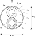
- Figure 13 is a cross-sectional view of the catheter in Figure 10 taken along line A-A.
- Figure 14 is a cross-sectional view of the catheter in Figure 10 taken along line B-B.
- Figure 15 is a cross-sectional view of the catheter in Figure 10 taken along line C-C.
- the catheter according to the second embodiment is a catheter 92 having a first tubular member 1 extending in the longitudinal direction X, a second tubular member 2 extending in the longitudinal direction X and adjacent to the first tubular member 1 in the radial direction Y, and an outer member 3 extending in the longitudinal direction X and having a portion that contains at least a portion of the first tubular member 1 and at least a portion of the second tubular member 2.
- a catheter 92 having a first tubular member 1 extending in the longitudinal direction X, a second tubular member 2 extending in the longitudinal direction X and adjacent to the first tubular member 1 in the radial direction Y, and an outer member 3 extending in the longitudinal direction X and having a portion that contains at least a portion of the first tubular member 1 and at least a portion of the second tubular member 2.
- the outer member 3 is cylindrical and has a lumen 3L extending in the longitudinal direction X, and it is preferable that at least a part of the first cylindrical member 1 and at least a part of the second cylindrical member 2 are disposed in the lumen 3L.
- This makes it possible to protect the first cylindrical member 1 and the second cylindrical member 2, and also allows each cylindrical member to move to some extent due to the gap between the outer member 3 and the first cylindrical member 1 and the gap between the outer member 3 and the second cylindrical member 2, so that the force of the wire can be released from inside the catheter 92. As a result, it is possible to easily prevent the wire from breaking through.
- the distal end of the cylindrical outer member 3 is preferably fixed to the first cylindrical member 1 and the second cylindrical member 2.
- the proximal end of the cylindrical outer member 3 is preferably fixed to the first cylindrical member 1 and the second cylindrical member 2. This makes it difficult for the cylindrical outer member 3 to twist or twist. Examples of the fixing method include welding and adhesion.
- the first region A1 and second region A2 of the cylindrical outer member 3 can be formed, for example, by joining two or more tubes with different major axis/minor axis values in the longitudinal direction X.
- a tube with a major axis/minor axis value of 1.0 to 1.1 can be prepared, and the second region A2 with a major axis/minor axis value of 1.2 to 2.0 can be formed by heating a portion of the tube and sandwiching it between plates or the like from both radial sides toward the inside while heating it. The same applies to the other regions.
- the cylindrical outer member 3 has at least a first region A1 and a second region A2, and more preferably has a third region A3 and/or a fifth region A5.
- first region A1 and a second region A2 and more preferably has a third region A3 and/or a fifth region A5.
- the first tubular member 1 and the second tubular member 2 are preferably fixed to each other in the radial direction Y.
- the outer surface of the first tubular member 1 and the outer surface of the second tubular member 2 are preferably fixed to each other in the radial direction Y. This makes the first tubular member 1 and the second tubular member 2 less likely to twist or distort. Examples of the manner of fixing include welding, adhesion, etc.
Landscapes
- Health & Medical Sciences (AREA)
- Life Sciences & Earth Sciences (AREA)
- Biophysics (AREA)
- Pulmonology (AREA)
- Engineering & Computer Science (AREA)
- Anesthesiology (AREA)
- Biomedical Technology (AREA)
- Heart & Thoracic Surgery (AREA)
- Hematology (AREA)
- Animal Behavior & Ethology (AREA)
- General Health & Medical Sciences (AREA)
- Public Health (AREA)
- Veterinary Medicine (AREA)
- Media Introduction/Drainage Providing Device (AREA)
Abstract
体内の蛇行部に挿入し易いカテーテルを提供する。長手方向に延在する第1筒状部材と、長手方向に延在し第1筒状部材と径方向に隣り合う第2筒状部材と、長手方向に延在し、第1筒状部材の少なくとも一部と第2筒状部材の少なくとも一部とを内包する部分を有する外側部材と、を有し、第1筒状部材の遠位端は第2筒状部材の遠位端よりも近位側に位置し、第1筒状部材の近位端は第2筒状部材の近位端よりも近位側に位置し、外側部材は、第2筒状部材の近位端から遠位側において、長手方向に延在する第1領域と、長手方向に延在し、第1領域よりも遠位側に位置する第2領域とを有しており、第1領域の径方向の断面における短径に対する長径の比の値は1.0~1.1であり、第2領域の径方向の断面における短径に対する長径の比の値は1.2~2.0であるカテーテル。
Description
本発明は、カテーテルに関する。
人体の病変部を検査・処置するために血管等に挿入することが可能なカテーテルが用いられている。このようなカテーテルとして、例えば特許文献1には、長手方向に延び、遠位端と近位端とを有し、ワイヤが挿入される第1筒状部材と、遠位端と近位端とを有し、前記第1筒状部材と径方向に隣接する第2筒状部材とを備え、前記第1筒状部材の遠位端は、前記第2筒状部材の遠位端よりも近位側に位置し、前記第1筒状部材の近位端は、前記第2筒状部材の近位端よりも近位側に位置し、前記第1筒状部材は、ポリテトラフルオロエチレン、及びテトラフルオロエチレン・パーフルオロアルキルビニルエーテル共重合体よりなる群から選択される少なくとも1種を含む内層と補強部材とを有する補強部を有し、前記第1筒状部材は、前記補強部の遠位端よりも遠位側には前記ポリテトラフルオロエチレンと前記テトラフルオロエチレン・パーフルオロアルキルビニルエーテル共重合体と前記補強部材とを含まない樹脂製の延在部を有するカテーテルが開示されている。
特許文献1のような従来のカテーテルは、冠動脈のように3次元の蛇行が連続するような血管に挿入する際に、挿入し難い場合があった。本発明は上記事情に鑑みてなされたものであり、その目的は、体内の蛇行部に挿入し易いカテーテルを提供することにある。
上記課題を解決することのできた本発明の実施の形態に係るカテーテルは、以下の通りである。
[1]長手方向に延在する第1筒状部材と、
前記長手方向に延在し、前記第1筒状部材と径方向に隣り合う第2筒状部材と、
前記長手方向に延在し、前記第1筒状部材の少なくとも一部と前記第2筒状部材の少なくとも一部とを内包する部分を有する外側部材と、を有するカテーテルであって、
前記第1筒状部材の遠位端は、前記第2筒状部材の遠位端よりも近位側に位置し、
前記第1筒状部材の近位端は、前記第2筒状部材の近位端よりも近位側に位置し、
前記外側部材は、前記第2筒状部材の前記近位端から遠位側において、前記長手方向に延在する第1領域と、前記長手方向に延在し、前記第1領域よりも遠位側に位置する第2領域とを有しており、前記第1領域の前記径方向の断面における短径に対する長径の比の値は1.0~1.1であり、前記第2領域の前記径方向の断面における短径に対する長径の比の値は1.2~2.0であるカテーテル。
[1]長手方向に延在する第1筒状部材と、
前記長手方向に延在し、前記第1筒状部材と径方向に隣り合う第2筒状部材と、
前記長手方向に延在し、前記第1筒状部材の少なくとも一部と前記第2筒状部材の少なくとも一部とを内包する部分を有する外側部材と、を有するカテーテルであって、
前記第1筒状部材の遠位端は、前記第2筒状部材の遠位端よりも近位側に位置し、
前記第1筒状部材の近位端は、前記第2筒状部材の近位端よりも近位側に位置し、
前記外側部材は、前記第2筒状部材の前記近位端から遠位側において、前記長手方向に延在する第1領域と、前記長手方向に延在し、前記第1領域よりも遠位側に位置する第2領域とを有しており、前記第1領域の前記径方向の断面における短径に対する長径の比の値は1.0~1.1であり、前記第2領域の前記径方向の断面における短径に対する長径の比の値は1.2~2.0であるカテーテル。
本発明者の検討により、特許文献1のような径方向の断面形状が円状のカテーテルは、冠動脈のように3次元の蛇行が連続する蛇行部において、蛇行部の形状に沿って湾曲し難いことが分かった。更に、本発明者の検討により、径方向の断面形状を楕円状にすれば、蛇行部の形状に沿ってカテーテルは湾曲し易くなる一方で、押し込み難くなることが分かった。更に本発明者が検討した結果、径方向の断面における長径/短径の値が1.2~2.0である第2領域を、長径/短径の値が1.0~1.1である第1領域よりも遠位側に配置することにより、カテーテルは蛇行部の形状に沿って湾曲し易くなり、且つ押し込み易くなることが分かった。これによりカテーテルは体内の蛇行部に挿入し易くなる。
更に実施の形態に係るカテーテルは、以下の[2]~[22]のいずれかであることが好ましい。
[2]前記第1領域の前記径方向の断面における外縁の形状は、円または楕円であり、
前記第2領域の前記径方向の断面における外縁の形状は、楕円または楕円の一部形状である[1]に記載のカテーテル。
[3]前記外側部材は、前記長手方向における前記第1領域と前記第2領域の間に第3領域を有しており、前記第3領域の前記径方向の断面における短径に対する長径の比の値が1.1超、1.2未満である[1]または[2]に記載のカテーテル。
[4]前記第2領域の前記長手方向における長さは、前記第1領域の前記長手方向における長さよりも短い[1]~[3]のいずれかに記載のカテーテル。
[5]前記第1領域の前記径方向の断面における外縁により囲まれた領域の面積は、前記第2領域の前記径方向の断面における外縁により囲まれた領域の面積よりも大きいか、または同じである[1]~[4]のいずれかに記載のカテーテル。
[6]前記第2領域の前記長径は、前記第1領域の前記長径よりも大きいか、または同じ長さである[1]~[5]のいずれかに記載のカテーテル。
[7]前記第2領域の前記長径は、前記第1領域の前記長径よりも小さい[1]~[5]のいずれかに記載のカテーテル。
[8]前記径方向において、前記外側部材の前記第2領域の外縁から前記第1筒状部材の外縁までの最短距離は、前記外側部材の前記第1領域の外縁から前記第1筒状部材の外縁までの最短距離よりも長いか、または同じ長さである[1]~[7]のいずれかに記載のカテーテル。
[9]前記径方向において、前記外側部材の前記第2領域の外縁から前記第1筒状部材の外縁までの最短距離は、前記外側部材の前記第1領域の外縁から前記第1筒状部材の外縁までの最短距離よりも短い[1]~[7]のいずれかに記載のカテーテル。
[10]前記径方向において、前記外側部材の前記第2領域の外縁から前記第2筒状部材の外縁までの最短距離は、前記外側部材の前記第1領域の外縁から前記第2筒状部材の外縁までの最短距離よりも長いか、または同じ長さである[1]~[9]のいずれかに記載のカテーテル。
[11]前記径方向において、前記外側部材の前記第2領域の外縁から前記第2筒状部材の外縁までの最短距離は、前記外側部材の前記第1領域の外縁から前記第2筒状部材の外縁までの最短距離よりも短い[1]~[9]のいずれかに記載のカテーテル。
[12]前記外側部材は、筒状であり、前記長手方向に延在する内腔を有しており、前記内腔に前記第1筒状部材の少なくとも一部と前記第2筒状部材の少なくとも一部が配置されている[1]~[11]のいずれかに記載のカテーテル。
[13]前記外側部材は、前記長手方向に延在し樹脂を含む柱体を有し、
前記第1筒状部材の少なくとも一部と前記第2筒状部材の少なくとも一部が前記柱体内に配置されている[1]~[11]のいずれかに記載のカテーテル。
[14]更に、前記長手方向に延在している外側筒状部材を有し、
前記外側筒状部材は、前記長手方向に延在する内腔を有しており、前記内腔に前記第1筒状部材の一部が配置されている[1]~[13]のいずれかに記載のカテーテル。
[15]前記外側筒状部材は、前記第2筒状部材の前記近位端よりも近位側に位置する[14]に記載のカテーテル。
[16]前記外側筒状部材は、前記第2筒状部材の前記近位端から近位側において、前記長手方向に延在する第4領域を有しており、前記第4領域の前記径方向の断面における短径に対する長径の比の値は1.0~1.1である[14]または[15]に記載のカテーテル。
[17]前記第2領域の前記長径は、前記第4領域の前記長径よりも小さい[16]に記載のカテーテル。
[18]前記第4領域の前記長手方向における長さは、前記第1領域の前記長手方向における長さと前記第2領域の前記長手方向における長さの合計よりも長い[16]または[17]に記載のカテーテル。
[19]前記長手方向に延在し、少なくとも前記第1領域と前記第4領域内に配置されており、且つ遠位端が前記第1領域内に位置する線状部材を有している[16]~[18]のいずれかに記載のカテーテル。
[20]前記外側部材は、前記長手方向に延在し、前記第2領域よりも遠位側に位置する第5領域を有しており、前記第5領域の前記径方向の断面における短径に対する長径の比の値は1.0~1.1である[1]~[19]のいずれかに記載のカテーテル。
[21]前記第1筒状部材と前記第2筒状部材は前記径方向において互いに固定されている[1]~[20]のいずれかに記載のカテーテル。
[22]前記第1筒状部材の近位端部にはハンドル部が配置されている[1]~[21]のいずれかに記載のカテーテル。
[2]前記第1領域の前記径方向の断面における外縁の形状は、円または楕円であり、
前記第2領域の前記径方向の断面における外縁の形状は、楕円または楕円の一部形状である[1]に記載のカテーテル。
[3]前記外側部材は、前記長手方向における前記第1領域と前記第2領域の間に第3領域を有しており、前記第3領域の前記径方向の断面における短径に対する長径の比の値が1.1超、1.2未満である[1]または[2]に記載のカテーテル。
[4]前記第2領域の前記長手方向における長さは、前記第1領域の前記長手方向における長さよりも短い[1]~[3]のいずれかに記載のカテーテル。
[5]前記第1領域の前記径方向の断面における外縁により囲まれた領域の面積は、前記第2領域の前記径方向の断面における外縁により囲まれた領域の面積よりも大きいか、または同じである[1]~[4]のいずれかに記載のカテーテル。
[6]前記第2領域の前記長径は、前記第1領域の前記長径よりも大きいか、または同じ長さである[1]~[5]のいずれかに記載のカテーテル。
[7]前記第2領域の前記長径は、前記第1領域の前記長径よりも小さい[1]~[5]のいずれかに記載のカテーテル。
[8]前記径方向において、前記外側部材の前記第2領域の外縁から前記第1筒状部材の外縁までの最短距離は、前記外側部材の前記第1領域の外縁から前記第1筒状部材の外縁までの最短距離よりも長いか、または同じ長さである[1]~[7]のいずれかに記載のカテーテル。
[9]前記径方向において、前記外側部材の前記第2領域の外縁から前記第1筒状部材の外縁までの最短距離は、前記外側部材の前記第1領域の外縁から前記第1筒状部材の外縁までの最短距離よりも短い[1]~[7]のいずれかに記載のカテーテル。
[10]前記径方向において、前記外側部材の前記第2領域の外縁から前記第2筒状部材の外縁までの最短距離は、前記外側部材の前記第1領域の外縁から前記第2筒状部材の外縁までの最短距離よりも長いか、または同じ長さである[1]~[9]のいずれかに記載のカテーテル。
[11]前記径方向において、前記外側部材の前記第2領域の外縁から前記第2筒状部材の外縁までの最短距離は、前記外側部材の前記第1領域の外縁から前記第2筒状部材の外縁までの最短距離よりも短い[1]~[9]のいずれかに記載のカテーテル。
[12]前記外側部材は、筒状であり、前記長手方向に延在する内腔を有しており、前記内腔に前記第1筒状部材の少なくとも一部と前記第2筒状部材の少なくとも一部が配置されている[1]~[11]のいずれかに記載のカテーテル。
[13]前記外側部材は、前記長手方向に延在し樹脂を含む柱体を有し、
前記第1筒状部材の少なくとも一部と前記第2筒状部材の少なくとも一部が前記柱体内に配置されている[1]~[11]のいずれかに記載のカテーテル。
[14]更に、前記長手方向に延在している外側筒状部材を有し、
前記外側筒状部材は、前記長手方向に延在する内腔を有しており、前記内腔に前記第1筒状部材の一部が配置されている[1]~[13]のいずれかに記載のカテーテル。
[15]前記外側筒状部材は、前記第2筒状部材の前記近位端よりも近位側に位置する[14]に記載のカテーテル。
[16]前記外側筒状部材は、前記第2筒状部材の前記近位端から近位側において、前記長手方向に延在する第4領域を有しており、前記第4領域の前記径方向の断面における短径に対する長径の比の値は1.0~1.1である[14]または[15]に記載のカテーテル。
[17]前記第2領域の前記長径は、前記第4領域の前記長径よりも小さい[16]に記載のカテーテル。
[18]前記第4領域の前記長手方向における長さは、前記第1領域の前記長手方向における長さと前記第2領域の前記長手方向における長さの合計よりも長い[16]または[17]に記載のカテーテル。
[19]前記長手方向に延在し、少なくとも前記第1領域と前記第4領域内に配置されており、且つ遠位端が前記第1領域内に位置する線状部材を有している[16]~[18]のいずれかに記載のカテーテル。
[20]前記外側部材は、前記長手方向に延在し、前記第2領域よりも遠位側に位置する第5領域を有しており、前記第5領域の前記径方向の断面における短径に対する長径の比の値は1.0~1.1である[1]~[19]のいずれかに記載のカテーテル。
[21]前記第1筒状部材と前記第2筒状部材は前記径方向において互いに固定されている[1]~[20]のいずれかに記載のカテーテル。
[22]前記第1筒状部材の近位端部にはハンドル部が配置されている[1]~[21]のいずれかに記載のカテーテル。
本発明によれば、上記構成により、体内の蛇行部に挿入し易いカテーテルを提供することができる。
以下では、下記実施の形態に基づき本発明をより具体的に説明するが、本発明はもとより下記実施の形態によって制限を受けるものではなく、前・後記の趣旨に適合し得る範囲で適当に変更を加えて実施することも勿論可能であり、それらはいずれも本発明の技術的範囲に包含される。なお、各図面において、便宜上、部材符号等を省略する場合もあるが、かかる場合、明細書や他の図面を参照するものとする。また、図面における種々部材の寸法は、本発明の特徴の理解に資することを優先しているため、実際の寸法とは異なる場合がある。
実施の形態に係るカテーテルは、長手方向に延在する第1筒状部材と、長手方向に延在し、第1筒状部材と径方向に隣り合う第2筒状部材と、長手方向に延在し、第1筒状部材の少なくとも一部と第2筒状部材の少なくとも一部とを内包する部分を有する外側部材と、を有するカテーテルであって、第1筒状部材の遠位端は、第2筒状部材の遠位端よりも近位側に位置し、第1筒状部材の近位端は、第2筒状部材の近位端よりも近位側に位置し、外側部材は、第2筒状部材の近位端から遠位側において、長手方向に延在する第1領域と、長手方向に延在し、第1領域よりも遠位側に位置する第2領域とを有しており、第1領域の径方向の断面における短径に対する長径の比の値は1.0~1.1であり、第2領域の径方向の断面における短径に対する長径の比の値は1.2~2.0である。
本発明者の検討により、径方向の断面形状が円状のカテーテルは、冠動脈のように3次元の蛇行が連続する蛇行部において、蛇行部の形状に沿って湾曲し難いことが分かった。更に、本発明者の検討により、径方向の断面形状を楕円状にすれば、蛇行部の形状に沿ってカテーテルは湾曲し易くなる一方で、押し込み難くなることが分かった。更に本発明者が検討した結果、径方向の断面における長径/短径の値が1.2~2.0である第2領域を、長径/短径の値が1.0~1.1である第1領域よりも遠位側に配置することにより、カテーテルは蛇行部の形状に沿って湾曲し易くなり、且つ押し込み易くなることが分かった。これによりカテーテルは体内の蛇行部に挿入し易くなる。
以下では図1~図9、図16を参照して、第1の実施の形態に係るカテーテルについて説明する。図1は、第1の実施の形態に係るカテーテルの側面図である。図2は、図1の領域R1の長手方向の断面図である。図3は、図1の領域R2の長手方向の断面図である。図4は、図1のカテーテルのA-A断面図である。図5は、図1のカテーテルのB-B断面図である。図6は、図1のカテーテルのC-C断面図である。図7は、図1のカテーテルのD-D断面図である。図8は、図1のカテーテルのE-E断面図である。図9は、図1のカテーテルの変形例における領域R2の長手方向の断面図である。図16は、図5のカテーテルの変形例の断面図である。
図1、図2、図3に示す通り、第1の実施の形態に係るカテーテルは、長手方向Xに延在する第1筒状部材1と、長手方向Xに延在し、第1筒状部材1と径方向Yに隣り合う第2筒状部材2とを有するカテーテル91である。具体的には、第1筒状部材1の外側面と第2筒状部材2の外側面が径方向Yにおいて互いに隣り合っていることが好ましい。第1筒状部材1は、長手方向Xに延在する内腔1Lを有していることが好ましい。第2筒状部材2は、長手方向Xに延在する内腔2Lを有していることが好ましい。内腔1Lと内腔2Lのそれぞれに、例えばガイドワイヤを挿入することにより、多方向にカテーテル91を誘導することができるため、例えば冠状動脈血管の様々な分岐部にカテーテル91を挿入し易くすることができる。また、内腔1Lまたは内腔2Lに探索用のワイヤを挿入することにより、病変部である狭窄部の入り口等を探索し易くすることができる。このうち内腔1Lに探索用のワイヤを挿入することが好ましい。探索用のワイヤの先端部は屈曲していてもよい。
第1筒状部材1と第2筒状部材2は、それぞれ、長手方向Xに延在する1つまたは複数の層を有していることが好ましく、複数の層を有していることがより好ましい。複数の層は、内層と、内層の少なくとも一部を内包する外層とを有していることが好ましい。複数の層は、更に、内層と外層の間に位置する中間層を有していてもよい。中間層の数は、1つに限らず2つ以上であってもよい。複数の層は、それぞれ隣接する層と異なる素材を含むことが好ましい。第1筒状部材1の内層と第2筒状部材2の内層は、それぞれ、ポリオレフィン系樹脂とフッ素系樹脂よりなる群から選択される少なくとも1種の樹脂を含むことが好ましい。これにより内腔1L、内腔2Lに挿入するワイヤの摺動性を向上させることができる。ポリオレフィン系樹脂は、ポリエチレン、ポリプロピレン、エチレン-プロピレン共重合体、またはこれらの混合物が好ましい。ポリエチレンは比重0.942以上の高密度ポリエチレンであることが好ましい。フッ素系樹脂は、ポリテトラフルオロエチレン、テトラフルオロエチレン・パーフルオロアルキルビニルエーテル共重合体、テトラフルオロエチレン・ヘキサフルオロプロピレン共重合体、テトラフルオロエチレン・エチレン共重合体、ポリビニリデンフルオライド、ポリクロロトリフルオロエチレン、エチレン-クロロトリフロオロエチレンコポリマー、またはこれらの混合物であることが好ましい。第1筒状部材1の内層と第2筒状部材2の内層は、それぞれ、ポリアミド系樹脂、ポリエステル系樹脂、ポリウレタン系樹脂、ポリオレフィン系樹脂、フッ素系樹脂、塩化ビニル系樹脂、シリコーン系樹脂、及び天然ゴムよりなる群から選択される少なくとも1種を含んでいてもよい。第1筒状部材1の内層と第2筒状部材2の内層は、互いに異なる樹脂を含んでいてもよく、同じ樹脂を含んでいることが好ましく、同じ樹脂からなることがより好ましい。
第1筒状部材1の外層と第2筒状部材2の外層は、それぞれ柔軟性樹脂を含むことが好ましい。外層が柔軟性樹脂を含むことによりカテーテル91は湾曲し易くなる。柔軟性樹脂は、ポリエチレン、ポリウレタン、ポリウレタン系熱可塑性エラストマー、スチレン系熱可塑性エラストマー、ポリアミドエラストマー、及びポリアミドからなる群より選ばれる少なくとも1種を含むことが好ましく、ポリウレタン及びポリアミドエラストマーからなる群より選ばれる少なくとも1種を含むことがより好ましい。ポリエチレンは、比重が0.91~0.92の低密度ポリエチレンであることが好ましい。
外層の素材のショアD硬度は、内層の素材のショアD硬度よりも小さいか、または同じであることが好ましく、小さいことがより好ましい。これにより、カテーテル91は湾曲し易くなる。ショアD硬度は、例えばデュロメータタイプDでISO7619に沿って測定すればよい。
中間層は、内層または外層と異なる素材を含んでいることが好ましいが、内層または外層と同じ素材を含んでいてもよい。
内層、中間層、外層は、それぞれ隣接する層に固定されていることが好ましい。これにより各層がよれたり捻れたりし難くなる。固定の態様としては、例えば溶着、接着等が挙げられる。図示していないが、中間層として補強部材が配置されていてもよい。
第1筒状部材1は、補強部材を備えていることが好ましい。これによりワイヤによる第1筒状部材1の突き破りを防止し易くすることができる。一方、第2筒状部材2は、補強部材を備えていないことが好ましい。これにより第2筒状部材2の柔軟性を向上し易くすることができる。
補強部材は、線材が編組された編組体、線材が螺旋状に巻回されたコイル体、またはこれらの組み合わせであることが好ましい。これにより、ワイヤによる第1筒状部材1の突き破りを防止し易くすることができる。これらのうち編組体が剛性を向上し易いため、補強部材は編組体であることがより好ましい。補強部材に含まれる線材として、例えば金属線、繊維等が挙げられる。金属線は、ステンレス鋼、チタン、ニッケルチタン合金、コバルトクロム合金、タングステン合金、またはこれらの合金を含むことが好ましい。このうちステンレス鋼がより好ましい。金属線は、単線であってもよいし、撚線であってもよい。繊維として、ポリアリレート繊維、アラミド繊維、超高分子量ポリエチレン繊維、PBO繊維、炭素繊維、またはこれらの混繊が好ましい。繊維は、モノフィラメントであってもよいし、マルチフィラメントであってもよい。補強部材は、第1筒状部材1の位置をX線透視下等で確認し易くするため、X線不透過性物質を含んでいてもよい。X線不透過性物質は、鉛、バリウム、ヨウ素、タングステン、金、白金、イリジウム、白金イリジウム合金、ステンレス、チタン、コバルトクロム合金、パラジウム、ビスマス、及びタンタルよりなる群から選択される少なくとも1種であることが好ましい。
図示していないが、補強部材の遠位端は、第1開口部1Eの近位端よりも近位側であって、第2筒状部材2の近位端2Aより遠位側に位置することが好ましい。一方、補強部材の近位端は、第2筒状部材2の近位端2Aよりも近位側に位置することが好ましく、ハンドル部8内に位置することがより好ましい。これによりワイヤによる第1筒状部材1の突き破りを防止し易くできる。
図2に示す通り、第1筒状部材1の遠位端1Bは、第2筒状部材2の遠位端2Bよりも近位側に位置している。これにより、カテーテル91は第1筒状部材1の遠位端1Bよりも遠位側の部分において湾曲し易くなる。
図1、図3に示す通り、第1筒状部材1の近位端1Aは、第2筒状部材2の近位端2Aよりも近位側に位置している。これにより、カテーテル91のうち第2筒状部材2の近位端2Aよりも近位側の部分を、例えば二重管構造(コアキシャル構造)の構造として、第2筒状部材2の近位端2Aよりも遠位側の第1筒状部材1と第2筒状部材2とが径方向Yに重なっている構造とは異なる構造とすることができ、異なる機能を発揮させることができる。
図1、図2、図3に示す通り、カテーテル91は、長手方向Xに延在し、第1筒状部材1の少なくとも一部と第2筒状部材2の少なくとも一部とを内包する部分を有する外側部材3を有している。外側部材3により、第1筒状部材1と第2筒状部材2を保護することができると共に、カテーテル91の内部からのワイヤの突き破りを防止し易くすることができる。
外側部材3は、ポリエチレン、ポリウレタン、ポリウレタン系熱可塑性エラストマー、スチレン系熱可塑性エラストマー、ポリアミドエラストマー、及びポリアミドからなる群から選択される少なくとも1種を含むことが好ましい。このうちポリウレタン、及びポリアミドエラストマーよりなる群から選択される少なくとも1種がより好ましい。
図1に示す通り、外側部材3は、第2筒状部材2の近位端2Aから遠位側において、長手方向Xに延在する第1領域A1と、長手方向Xに延在し、第1領域A1よりも遠位側に位置する第2領域A2とを有している。図4に示す通り、第1領域A1の径方向Yの断面における短径A1mに対する長径A1lの比の値は1.0~1.1である。図5に示す通り、第2領域A2の径方向Yの断面における短径A2mに対する長径A2lの比の値は1.2~2.0である。第1領域A1の長径A1l/短径A1mの値が1.0~1.1であることにより、カテーテル91は体内の蛇行部において捻れ難くなるため、近位側から遠位側に向かう力を伝達し易くなる。一方、第1領域A1よりも遠位側の第2領域A2の長径A2l/短径A2mの値が1.2~2.0であることにより、カテーテル91は体内の蛇行部の形状に沿って湾曲し易くなる。長径A2l/短径A2mの値は、好ましくは1.2~1.9であり、より好ましくは1.2~1.7であり、更に好ましくは1.2~1.5である。なお外側部材3は、第2筒状部材2の近位端2Aから遠位側において、第1領域A1を有していればよく、第1領域A1は、第2筒状部材2の近位端2Aよりも遠位側に位置していてもよい。第1領域A1の長径A1lの長さは、0.5mm以上、2.0mm以下であることが好ましく、0.7mm以上、1.6mm以下であることがより好ましい。
本書において、各領域の径方向Yの断面における長径は、各領域の径方向Yの断面における外縁上の2点を結び且つ図心を通る線分のうち最も長い線分の長さのことを意味する。また当該断面形状が、後述する楕円の一部形状である場合には、外接する仮想楕円の長径を、径方向Yの断面における長径とする。また本書において、各領域の径方向Yの断面における短径は、各領域の径方向Yの断面における外縁上の2点を結び且つ図心を通る線分のうち最も短い線分の長さのことを意味する。また当該断面形状が、後述する楕円の一部形状である場合には、外接する仮想楕円の短径を、径方向Yの断面における短径とする。なお径方向Yの断面における外縁の形状が円形である場合には、長径と短径の長さは同じ長さとなる。
図4に示す通り、第1領域A1の径方向Yの断面における外縁A1eの形状は、円または楕円であることが好ましく、円であることがより好ましい。これにより、第1領域A1は体内の蛇行部において捻れ難くなるため、カテーテル91は近位側から遠位側に向かう力を伝達し易くなる。第1領域A1の径方向Yの断面における外縁A1eの形状は、角丸多角形等の形状であってもよい。第1領域A1は、径方向Yの断面形状が互いに異なる部分を有していてもよい。
図5に示す通り、第2領域A2の径方向Yの断面における外縁A2eの形状は、楕円であることが好ましい。これにより、第2領域A2は体内の蛇行部の形状に沿って湾曲し易くなるため、カテーテル91は、体内の蛇行部の形状に沿って湾曲し易くなる。また例えば第1開口部1E近傍では、第2領域A2の径方向Yの断面における外縁A2eの形状は、楕円の一部形状であることが好ましい。楕円の一部形状とは、楕円の一部を切り欠いた後の形状である。なお第2領域A2の径方向Yの断面における外縁A2eの形状は、角丸多角形等の形状であってもよい。第2領域A2は、径方向Yの断面形状が互いに異なる部分を有していてもよい。
図4、図5に示す通り、第1領域A1の径方向Yの断面における外縁A1eにより囲まれた領域の面積は、第2領域A2の径方向Yの断面における外縁A2eにより囲まれた領域の面積よりも大きいか、または同じであることが好ましく、大きいことがより好ましい。これにより、カテーテル91は体内の蛇行部に一層、挿入し易くなる。第1領域A1の径方向Yの断面における外縁A1eにより囲まれた領域の面積は、第2領域A2の径方向Yの断面における外縁A2eにより囲まれた領域の面積の1.00倍以上、2.00倍以下であることが好ましく、1.01倍以上、1.50倍以下であることがより好ましい。
第2領域A2の長径A2lは、第1領域A1の長径A1lよりも大きいか、または同じ長さであることが好ましく、第1領域A1の長径A1lよりも大きいことがより好ましい。これにより、第2領域A2は、近位側から遠位側に向かう力を伝達し易くなる。
図4、図16に示す通り、第2領域A2の長径A2lは、第1領域A1の長径A1lよりも小さくてもよい。この場合、第2領域A2の柔軟性が向上する。
図4、図5に示す通り、径方向Yにおいて、外側部材3の第2領域A2の外縁A2eから第1筒状部材1の外縁1eまでの最短距離は、外側部材3の第1領域A1の外縁A1eから第1筒状部材1の外縁1eまでの最短距離よりも長いか、または同じ長さであることが好ましく、外縁A1eから外縁1eまでの最短距離よりも長いことがより好ましい。これにより、例えば第2領域A2の蛇行している部分にワイヤを挿入しても、ワイヤは第1筒状部材1と第2領域A2とを突き破り難くなる。第2領域A2の当該最短距離は、第2領域A2のうち径方向Yの断面形状が楕円である部分において測定するものとする。以下、第2領域A2の当該最短距離について同様である。
図4、図16に示す通り、径方向Yにおいて、外側部材3の第2領域A2の外縁A2eから第1筒状部材1の外縁1eまでの最短距離は、外側部材3の第1領域A1の外縁A1eから第1筒状部材1の外縁1eまでの最短距離よりも短くてもよい。この場合、第1筒状部材1近傍における第2領域A2が蛇行部への挿入時によれ難くなる。
径方向Yにおいて、外側部材3の第2領域A2の外縁A2eから第2筒状部材2の外縁2eまでの最短距離は、外側部材3の第1領域A1の外縁A1eから第2筒状部材2の外縁2eまでの最短距離よりも長いか、または同じ長さであることが好ましく、外縁A1eから外縁2eまでの最短距離よりも長いことがより好ましい。これにより、例えば第2領域A2の蛇行している部分にワイヤを挿入しても、ワイヤは第2筒状部材2と第2領域A2とを突き破り難くなる。第2領域A2の当該最短距離は、第2領域A2のうち径方向Yの断面形状が楕円である部分において測定するものとする。以下、第2領域A2の当該最短距離について同様である。
図4、図16に示す通り、径方向Yにおいて、外側部材3の第2領域A2の外縁A2eから第2筒状部材2の外縁2eまでの最短距離は、外側部材3の第1領域A1の外縁A1eから第2筒状部材2の外縁2eまでの最短距離よりも短くてもよい。この場合、第2筒状部材2近傍における第2領域A2が蛇行部への挿入時によれ難くなる。
図1に示す通り、第2領域A2の長手方向Xにおける長さは、第1領域A1の長手方向Xにおける長さよりも短いことが好ましい。これにより、カテーテル91を体内の蛇行部に一層、挿入し易くなる。具体的には、第1領域A1の長手方向Xにおける長さは、第2領域A2の長手方向Xにおける長さの1.1倍以上、30倍以下であることが好ましく、1.2倍以上、20倍以下であることがより好ましい。
図1、図6に示す通り、外側部材3は、長手方向Xにおける第1領域A1と第2領域A2の間に第3領域A3を有しており、第3領域A3の径方向Yの断面における短径A3mに対する長径A3lの比の値が1.1超、1.2未満であることが好ましい。第3領域A3により、第1領域A1と第2領域A2の間の急な形状変化に伴う屈曲を回避し易くなる。そのため、長手方向Xにおいて第1領域A1と第3領域A3は隣接し、且つ長手方向Xにおいて第3領域A3と第2領域A2は隣接していることがより好ましい。長手方向Xにおける第3領域A3の長さは、1mm以上、20mm以下であることが好ましく、3mm以上、10mm以下であることがより好ましい。
第3領域A3は、近位側から遠位側に向かうに従って長径A3l/短径A3mの値が小さくなることが好ましい。これにより第1領域A1と第2領域A2の間の急な形状変化に伴う屈曲をより一層、回避し易くなる。第3領域A3の径方向Yの断面における外縁A3eの形状は楕円であることが好ましい。これにより上記効果が発揮され易くなる。なお第3領域A3の径方向Yの断面における外縁A3eの形状は、角丸多角形等の形状であってもよい。
図2に示す通り、外側部材3の遠位端3Bは、第2筒状部材2の遠位端2Bよりも遠位側に位置していることが好ましい。柔軟な素材により形成された外側部材3をこのように配置することにより、カテーテル91の第2筒状部材2の遠位端2Bよりも遠位側の部分の柔軟性を向上させることができる。
外側部材3の内側面の少なくとも一部は、第1筒状部材1と第2筒状部材2の外側面に固定されていることが好ましい。これにより外側部材3がよれたり捻れたりし難くなる。固定の態様としては、例えば溶着、接着等が挙げられる。
外側部材3の遠位端3Bから第2筒状部材2の遠位端2Bまでの長手方向Xにおける長さは、第2筒状部材2の最大厚みよりも大きいことが好ましい。これにより、カテーテル91の遠位端の近傍の柔軟性を向上させることができる。
図4、図5、図6等に示す通り、第1筒状部材1と第2筒状部材2の外側面は、互いに接触していなくてもよいし、互いに接触して固定されていてもよい。固定の態様としては、例えば溶着、接着等が挙げられる。第1筒状部材1の外側面と第2筒状部材2の外側面が接触していない場合には、これらは外側部材3の樹脂を介して互いに固定されていることが好ましい。また図4、図5、図6等に示す通り、カテーテル91の径方向Yの断面において、第1内腔1Lと第2内腔2Lの形状は、それぞれ円形、楕円形、弓形、またはこれらの組み合わせ形状であることが好ましく、円形または楕円形であることがより好ましい。これによりカテーテル91は湾曲し易くなる。カテーテル91内において、第1内腔1Lと第2内腔2Lは連通していないことが好ましい。径方向Yの断面において、第1内腔1Lは、第2内腔2Lより面積が大きくてもよく、第2内腔2Lより面積が小さくてもよく、第2内腔2Lと面積が同じであってもよい。
図2に示す通り、第1筒状部材1は、内腔1Lに連通する第1開口部1Eを有していることが好ましい。第1開口部1Eをワイヤの入口、または出口とすることができる。
図2に示す通り、第2筒状部材2は、内腔2Lに連通する第2開口部2Eを有していることが好ましい。第2開口部2Eをワイヤの入口、または出口とすることができる。
外側部材3は、第1筒状部材1の遠位端1Bよりも遠位側であって、径方向Yにおける第1筒状部材1に近い側において、中心軸2Cから離れる方向に隆起している隆起部34を有することが好ましい。これにより第1筒状部材1に挿入するワイヤの先端を第2筒状部材2に挿入するワイヤの先端とは異なる向きに誘導することができるため、分岐部病変等に対する処置を行い易くすることができる。またこれにより、それぞれのワイヤを絡み難くすることができる。隆起部34は第1筒状部材1の遠位端1Bに隣接していることが好ましい。これにより第1開口部1Eから出てきたワイヤを隆起部34により誘導し易くなる。
図2に示す通り、第1筒状部材1の中心軸1Cと第2筒状部材2の中心軸2Cとを含む長手方向Xの断面を断面Xとしたとき、隆起部34は、断面Xにおいて、遠位側に向かうに従って中心軸2Cから離れる方向に傾斜している第1傾斜部と、遠位側に向かうに従って中心軸2Cに近づくように傾斜している第2傾斜部とを有していることが好ましい。第2傾斜部は、第1傾斜部よりも遠位側に位置することが好ましい。第1傾斜部により、第1開口部1Eから出てきたワイヤを誘導し易くなる。第2傾斜部により、体内に挿入し易くなる。断面Xにおける第1傾斜部と第2傾斜部の外側面の形状は、直線状または湾曲状であることが好ましく、直線状であることがより好ましい。断面Xの第2傾斜部の外側面が直線状である場合、第2傾斜部の形状はいわゆるテーパ形状である。
一方、図示していないが第2筒状部材2は、第1筒状部材1の遠位端1Bよりも遠位側であって、径方向Yにおける第1筒状部材1に近い側において、中心軸2Cから離れる方向に隆起している隆起部を有していなくてもよい。これにより、隆起部の分だけカテーテル91の外径が小さくなるため、カテーテル91が湾曲し易くなる。
第1筒状部材1と第2筒状部材2の外径は、それぞれ、0.2mm以上、0.8mm以下であることが好ましく、0.3mm以上、0.7mm以下であることがより好ましい。これによりカテーテル91を冠状動脈血管の蛇行部に一層、挿入し易くなる。
図1に示す通り、第1筒状部材1の近位端部1aにはハンドル部8が配置されていることが好ましい。具体的にはハンドル部8内に第1筒状部材1の近位端部1aが配置されていることが好ましい。施術者は、ハンドル部8を把持して押すことにより、カテーテル91を体内に挿入することができる。ハンドル部8の外形は、施術者が指で把持できるような形状になっていればよい。ハンドル部8は、射出成形等により得られる樹脂成形品であることが好ましい。樹脂として、例えば、ポリエチレン、ポリプロピレン等のポリオレフィン系樹脂、ポリカーボネート系樹脂、(メタ)アクリル系樹脂等が挙げられる。これらの樹脂のうちポリカーボネート、ポリメタクリル酸メチル等の透明性樹脂が好ましい。これによりハンドル部8の内部が見え易くなって、ワイヤを挿入し易くすることができる。
第1筒状部材1の近位端1Aは、ハンドル部8内に位置することが好ましい。これによりプッシャビリティーを向上させることができる。
ハンドル部8は、第1筒状部材1の内腔1Lに連通し、長手方向Xに延在する内腔を有していることが好ましい、当該内腔からワイヤを挿入することができる。
図1、図3に示す通り、カテーテル91は、更に、長手方向Xに延在している外側筒状部材4を有していることが好ましい。外側筒状部材4は、長手方向Xに延在する内腔4Lを有しており、内腔4Lに第1筒状部材1の一部が配置されていることが好ましい。外側筒状部材4により、二重管構造(コアキシャル構造)を形成することができ、第1筒状部材1を保護しつつ、押し込み力の伝達性を向上することができる。具体的には、外側筒状部材4は、遠位端部において第1筒状部材1に固定されている固定部と、固定部よりも近位側において第1筒状部材1に固定されていない非固定部を有していることが好ましい。非固定部により、第1筒状部材1へのワイヤの挿入に伴う力を逃がし易くすることができる。そのため、長手方向Xにおいて非固定部は固定部よりも長いことが好ましい。これによりワイヤによる第1筒状部材1の突き破りのリスクを低減することができる。また、外側筒状部材4は、近位端部においてハンドル部8に固定されている固定部を有していることが好ましい。
外側筒状部材4は、第2筒状部材2の近位端2Aよりも近位側に位置することが好ましい。これにより外側筒状部材4の外径を低減することができる。
外側筒状部材4は、外側部材3と同じ樹脂かより硬い樹脂を含んでいることが好ましく、より硬い樹脂からなることがより好ましい。より硬い樹脂によりプッシャビリティーを向上させることができる。また、外側筒状部材4の遠位端と外側部材3の近位端は、互いに固定されいることが好ましい。
図1、図7に示す通り、外側筒状部材4は、第2筒状部材2の近位端2Aから近位側において、長手方向Xに延在する第4領域A4を有しており、第4領域A4の径方向Yの断面における短径A4mに対する長径A4lの比の値は1.0~1.1であることが好ましい。長径A4l/短径A4mの値が1.0~1.1であることにより、カテーテル91は体内の蛇行部において捻れ難くなるため、近位側から遠位側に向かう力を伝達し易くなる。
外側筒状部材4は、第2筒状部材2の近位端2Aから近位側において、第4領域A4を有していればよく、第4領域A4は、第2筒状部材2の近位端2Aよりも近位側に位置していてもよい。
図5、図7に示す通り、第2領域A2の長径A2lは、第4領域A4の長径A4lよりも小さいことが好ましい。これにより第2領域A2は体内の蛇行部において一層、湾曲し易くなる。長径A2lは、長径A4lの0.99倍以下であることが好ましく、0.98倍以下であることがより好ましい。一方、長径A2lは、長径A4lの0.5倍以上であることが好ましく、0.6倍以上であることがより好ましい。これにより第2領域A2のプッシャビリティーを向上させることができる。
図1に示す通り、第4領域A4の長手方向Xにおける長さは、第1領域A1の長手方向Xにおける長さと第2領域A2の長手方向Xにおける長さの合計よりも長いことが好ましい。これにより、カテーテル91のプッシャビリティーを向上させることができる。長手方向Xにおいて、第4領域A4の長さは、第1領域A1と第2領域A2の長さの合計の2倍以上であることが好ましく、3倍以上であることがより好ましい。一方、当該倍率は、14倍以下であることが好ましく、6倍以下であることがより好ましい。これによりカテーテル91の長さを低減することができる。長手方向Xにおける第1領域A1と第2領域A2の長さの合計は、5cm以上、50cm以下であることが好ましく、10cm以上、40cm以下であることがより好ましい。
図1、図8に示す通り、外側部材3は、長手方向Xに延在し、第2領域A2よりも遠位側に位置する第5領域A5を有しており、第5領域A5の径方向Yの断面における短径A5mに対する長径A5lの比の値は1.0~1.1であることが好ましい。長径A5l/短径A5mの値が1.0~1.1であることにより、カテーテル91の遠位端近傍の捻れ等の変形を防止し易くなる。そのため第5領域A5は、カテーテル91の遠位端を含んでいることが好ましい。長手方向Xにおいて第5領域A5は第2領域A2と隣接していることが好ましいが、第5領域A5と第2領域A2の間に他の領域が存在していてもよい。他の領域の径方向Yの断面における短径に対する長径の比の値は1.1超、1.2未満であることが好ましい。これにより急な形状変化に伴う屈曲を回避し易くなる。
図4~図6等に示す通り、外側部材3は、長手方向Xに延在し樹脂を含む柱体5を有し、第1筒状部材1の少なくとも一部と第2筒状部材2の少なくとも一部が柱体5内に配置されていることが好ましい。即ち、第1筒状部材1と第2筒状部材2の少なくとも一部は、長手方向Xに延在し樹脂を含む柱体5により封止されていることが好ましい。これにより、カテーテル91が湾曲しても長手方向Xに延在する内腔1Lと内腔2Lの形状が維持され易くなる。柱体5は、少なくとも第1領域A1と第2領域A2を有し、更に第3領域A3および/または第5領域A5を有していることがより好ましい。各領域の詳細については、上述した筒状の外側部材3の各領域の記載を参照すればよい。なお第1筒状部材1と第2筒状部材2の間には、柱体5の樹脂が存在していてもよい。
柱体5は、楕円柱状部、円柱状部、または楕円柱状部と円柱状部を有していることが好ましい。柱体5は、長径/短径の値が互いに異なる複数の楕円柱状部を有していることがより好ましい。複数の楕円柱状部は長手方向Xに隣り合っていることが好ましい。各楕円柱状部は、長径/短径の値が一定である部分であってもよく、長径/短径の値が遠位側に向かうに従って変化する部分であってもよい。また柱体5が楕円柱状部と円柱状部を有する場合、楕円柱状部と円柱状部は長手方向Xに隣り合っていることが好ましい。
柱体5は、例えば長径/短径の値が異なる2つ以上のチューブを長手方向Xに隣り合うように配置し、第1筒状部材1と第2筒状部材2を径方向Yに重ねた状態でこれらのチューブの内部に配置し、これらのチューブを加熱して第1筒状部材1と第2筒状部材2に溶着させることによって形成することができる。その他に柱体5は、長径/短径の値が1.0~1.1であるチューブを用意し、第1筒状部材1と第2筒状部材2を径方向Yに重ねた状態でチューブの内部に配置し、チューブを加熱しながらチューブの一部を径方向の両側から内側に向かって板等により挟みながら、チューブを第1筒状部材1と第2筒状部材2に溶着させることによって形成することができる。この場合、板等により挟んだ部分の長径/短径の値が1.2~2.0とすることにより第2領域A2を形成することもできる。他の領域についても同様である。
図2に示す通り、第1筒状部材1は、第1開口部1Eの近位端よりも近位側であって、第1開口部1Eの近位端から近位側に1cm離れた点よりも遠位側において、X線不透過性マーカー6Aを有していてもよい。これにより、第1開口部1Eの位置を把握し易くすることができる。
第2筒状部材2は、第1筒状部材1の遠位端1Bよりも遠位側であって、第2筒状部材2の遠位端2Bよりも近位側の位置に、X線不透過性マーカー6Bを有していてもよい。これにより、体内の蛇行部にカテーテル91を挿入するときに、カテーテル91の湾曲部の位置を把握し易くなるため、挿入し易くなる。
X線不透過性マーカーは、リング状であることが好ましい。X線不透過性マーカーは、X線不透過性物質を含むことが好ましく、X線不透過性物質からなることがより好ましい。X線不透過性物質は、鉛、バリウム、ヨウ素、タングステン、金、白金、イリジウム、白金イリジウム合金、ステンレス、チタン、コバルトクロム合金、パラジウム、ビスマス、及びタンタルよりなる群から選択される少なくとも1種であることが好ましい。
図9に示す通り、カテーテル91は、長手方向Xに延在し、少なくとも第1領域A1と第4領域A4内に配置されており、且つ遠位端11Bが第1領域A1内に位置する線状部材11を有していることが好ましい。これによりプッシャビリティーを向上することができる。
線状部材11は、金属を含むことが好ましく、金属からなることがより好ましい。金属は、ステンレス、ニッケルチタン、コバルトクロム、またはこれらの合金が好ましい。これによりプッシャビリティーを一層、向上することができる。
線状部材11の形状は、直線状であることが好ましい。線状部材11は、内腔を有していない中実部材であることが好ましい。これによりプッシャビリティーを一層、向上することができる。カテーテル91が有する線状部材11の数は、1本であってもよいし、2本以上であってもよい。
線状部材11は、長手方向Xに延在し径方向の長さが一定である定径部11Uを有していることが好ましい。線状部材11は、更に、定径部11Uよりも遠位側に位置し、遠位側に向かって先細り形状になっているテーパ部11Tを有していることがより好ましい。
図示していないが線状部材11の近位端は、ハンドル部8内に位置することが好ましい。線状部材11の近位端部は、第1筒状部材1、ハンドル部8、または外側筒状部材4に固定されていることが好ましい。これによりプッシャビリティーを一層、向上することができる。
図示していないが、カテーテル91は、更に、長手方向Xに延在するチップを有していてもよい。チップは、長手方向Xに延在する内腔を有し、内腔内に少なくとも第2筒状部材2の遠位端部が配置されていることが好ましい。これにより、チップと第2筒状部材2は、一体的に湾曲し易くなる。
チップの内側面の少なくとも一部は、第2筒状部材2の外側面に固定されていることが好ましい。これによりチップと第2筒状部材2は、より一層、一体的に湾曲し易くなる。固定の態様としては、例えば溶着、接着等が挙げられる。
チップは、柔軟性樹脂を含むことが好ましい。柔軟性樹脂は、ポリエチレン、ポリウレタン、ポリウレタン系熱可塑性エラストマー、スチレン系熱可塑性エラストマー、ポリアミドエラストマー、及びポリアミドからなる群より選ばれる少なくとも1種を含むことが好ましく、ポリウレタン及びポリアミドエラストマーからなる群より選ばれる少なくとも1種を含むことがより好ましい。ポリエチレンは、比重が0.91~0.92の低密度ポリエチレンであることが好ましい。
チップは、径方向Yの断面における短径に対する長径の比の値が1.0~1.1である領域を有していることが好ましい。当該領域は、チップの遠位端を含むことが好ましい。これによりチップの遠位端部の捻れ等の変形を防止し易くなる。チップは当該領域からなることがより好ましい。
カテーテル91は、体内の血管等の通路の狭窄や閉塞部位を拡張する治療に好ましく用いることができ、冠状動脈血管の分岐部病変等に対する冠血管インターベンション(PCI)の施行により好ましく用いることができる。
以下では、図10~図15を参照しながら、第2の実施の形態に係るカテーテルについて説明する。図10は、第2の実施の形態に係るカテーテルの側面図である。図11は、図10の領域R1の長手方向の断面図である。図12は、図10の領域R2の長手方向の断面図である。図13は、図10のカテーテルのA-A断面図である。図14は、図10のカテーテルのB-B断面図である。図15は、図10のカテーテルのC-C断面図である。第2の実施の形態に係るカテーテルのうち、第1の実施の形態に係るカテーテルと重複する部分の詳細な説明は省略する。
第2の実施の形態に係るカテーテルは、長手方向Xに延在する第1筒状部材1と、長手方向Xに延在し、第1筒状部材1と径方向Yに隣り合う第2筒状部材2と、長手方向Xに延在し、第1筒状部材1の少なくとも一部と第2筒状部材2の少なくとも一部とを内包する部分を有する外側部材3を有するカテーテル92である。各部の詳細はカテーテル91の説明を参照すればよい。
図10~図15に示すようにカテーテル92において、外側部材3は、筒状であり、長手方向Xに延在する内腔3Lを有しており、内腔3Lに第1筒状部材1の少なくとも一部と第2筒状部材2の少なくとも一部が配置されていることが好ましい。これにより、第1筒状部材1と第2筒状部材2を保護することができると共に、外側部材3と第1筒状部材1の間の隙間、外側部材3と第2筒状部材2との間の隙間により、各筒状部材がある程度動くことができるためカテーテル92の内部からのワイヤの力を逃がすことができる。その結果、ワイヤの突き破りを防止し易くすることができる。筒状の外側部材3は、遠位端部が第1筒状部材1と第2筒状部材2に固定されていることが好ましい。筒状の外側部材3は、近位端部が第1筒状部材1と第2筒状部材2に固定されていることが好ましい。これにより筒状の外側部材3は、よれたり捻れたりし難くなる。固定の態様としては、例えば溶着、接着等が挙げられる。
筒状の外側部材3の第1領域A1と第2領域A2等は、例えば長径/短径の値が異なる2つ以上のチューブを長手方向Xに結合することにより形成することができる。その他に、長径/短径の値が1.0~1.1であるチューブを用意し、チューブの一部を加熱しながら径方向の両側から内側に向かって板等により挟みこむことにより、長径/短径の値が1.2~2.0である第2領域A2を形成してもよい。他の領域についても同様である。
筒状の外側部材3は、少なくとも第1領域A1と第2領域A2を有し、更に第3領域A3および/または第5領域A5を有していることがより好ましい。各領域の詳細については、上述した筒状の外側部材3の各領域の記載を参照すればよい。
カテーテル92において、第1筒状部材1と第2筒状部材2は径方向Yにおいて互いに固定されていることが好ましい。具体的には、第1筒状部材1の外側面と第2筒状部材2の外側面は径方向Yにおいて互いに固定されていることが好ましい。これにより第1筒状部材1と第2筒状部材2は、よれたり捻れたりし難くなる。固定の態様としては、例えば溶着、接着等が挙げられる。
本願は、2023年8月1日に出願された日本国特許出願第2023-125557号に基づく優先権の利益を主張するものである。2023年8月1日に出願された日本国特許出願第2023-125557号の明細書の全内容が、本願に参考のため援用される。
1 第1筒状部材
1a 近位端部
1e 外縁
1A 近位端
1B 遠位端
1C 中心軸
1E 第1開口部
1L 内腔
2 第2筒状部材
2e 外縁
2A 近位端
2B 遠位端
2C 中心軸
2E 第2開口部
2L 内腔
3 外側部材
3B 遠位端
3L 内腔
4 外側筒状部材
4L 内腔
5 柱体
6A、6B X線不透過性マーカー
8 ハンドル部
11 線状部材
11B 遠位端
11U 定径部
11T テーパ部
34 隆起部
91、92 カテーテル
A1 第1領域
A1e 外縁
A1l 長径
A1m 短径
A2 第2領域
A2e 外縁
A2l 長径
A2m 短径
A3 第3領域
A3e 外縁
A3l 長径
A3m 短径
A4 第4領域
A4l 長径
A4m 短径
A5 第5領域
A5l 長径
A5m 短径
X 長手方向
Y 径方向
1a 近位端部
1e 外縁
1A 近位端
1B 遠位端
1C 中心軸
1E 第1開口部
1L 内腔
2 第2筒状部材
2e 外縁
2A 近位端
2B 遠位端
2C 中心軸
2E 第2開口部
2L 内腔
3 外側部材
3B 遠位端
3L 内腔
4 外側筒状部材
4L 内腔
5 柱体
6A、6B X線不透過性マーカー
8 ハンドル部
11 線状部材
11B 遠位端
11U 定径部
11T テーパ部
34 隆起部
91、92 カテーテル
A1 第1領域
A1e 外縁
A1l 長径
A1m 短径
A2 第2領域
A2e 外縁
A2l 長径
A2m 短径
A3 第3領域
A3e 外縁
A3l 長径
A3m 短径
A4 第4領域
A4l 長径
A4m 短径
A5 第5領域
A5l 長径
A5m 短径
X 長手方向
Y 径方向
Claims (22)
- 長手方向に延在する第1筒状部材と、
前記長手方向に延在し、前記第1筒状部材と径方向に隣り合う第2筒状部材と、
前記長手方向に延在し、前記第1筒状部材の少なくとも一部と前記第2筒状部材の少なくとも一部とを内包する部分を有する外側部材と、を有するカテーテルであって、
前記第1筒状部材の遠位端は、前記第2筒状部材の遠位端よりも近位側に位置し、
前記第1筒状部材の近位端は、前記第2筒状部材の近位端よりも近位側に位置し、
前記外側部材は、前記第2筒状部材の前記近位端から遠位側において、前記長手方向に延在する第1領域と、前記長手方向に延在し、前記第1領域よりも遠位側に位置する第2領域とを有しており、前記第1領域の前記径方向の断面における短径に対する長径の比の値は1.0~1.1であり、前記第2領域の前記径方向の断面における短径に対する長径の比の値は1.2~2.0であるカテーテル。 - 前記第1領域の前記径方向の断面における外縁の形状は、円または楕円であり、
前記第2領域の前記径方向の断面における外縁の形状は、楕円または楕円の一部形状である請求項1に記載のカテーテル。 - 前記外側部材は、前記長手方向における前記第1領域と前記第2領域の間に第3領域を有しており、前記第3領域の前記径方向の断面における短径に対する長径の比の値が1.1超、1.2未満である請求項1または2に記載のカテーテル。
- 前記第2領域の前記長手方向における長さは、前記第1領域の前記長手方向における長さよりも短い請求項1または2に記載のカテーテル。
- 前記第1領域の前記径方向の断面における外縁により囲まれた領域の面積は、前記第2領域の前記径方向の断面における外縁により囲まれた領域の面積よりも大きいか、または同じである請求項1または2に記載のカテーテル。
- 前記第2領域の前記長径は、前記第1領域の前記長径よりも大きいか、または同じ長さである請求項1または2に記載のカテーテル。
- 前記第2領域の前記長径は、前記第1領域の前記長径よりも小さい請求項1または2に記載のカテーテル。
- 前記径方向において、前記外側部材の前記第2領域の外縁から前記第1筒状部材の外縁までの最短距離は、前記外側部材の前記第1領域の外縁から前記第1筒状部材の外縁までの最短距離よりも長いか、または同じ長さである請求項1または2に記載のカテーテル。
- 前記径方向において、前記外側部材の前記第2領域の外縁から前記第1筒状部材の外縁までの最短距離は、前記外側部材の前記第1領域の外縁から前記第1筒状部材の外縁までの最短距離よりも短い請求項1または2に記載のカテーテル。
- 前記径方向において、前記外側部材の前記第2領域の外縁から前記第2筒状部材の外縁までの最短距離は、前記外側部材の前記第1領域の外縁から前記第2筒状部材の外縁までの最短距離よりも長いか、または同じ長さである請求項1または2に記載のカテーテル。
- 前記径方向において、前記外側部材の前記第2領域の外縁から前記第2筒状部材の外縁までの最短距離は、前記外側部材の前記第1領域の外縁から前記第2筒状部材の外縁までの最短距離よりも短い請求項1または2に記載のカテーテル。
- 前記外側部材は、筒状であり、前記長手方向に延在する内腔を有しており、前記内腔に前記第1筒状部材の少なくとも一部と前記第2筒状部材の少なくとも一部が配置されている請求項1または2に記載のカテーテル。
- 前記外側部材は、前記長手方向に延在し樹脂を含む柱体を有し、
前記第1筒状部材の少なくとも一部と前記第2筒状部材の少なくとも一部が前記柱体内に配置されている請求項1または2に記載のカテーテル。 - 更に、前記長手方向に延在している外側筒状部材を有し、
前記外側筒状部材は、前記長手方向に延在する内腔を有しており、前記内腔に前記第1筒状部材の一部が配置されている請求項1または2に記載のカテーテル。 - 前記外側筒状部材は、前記第2筒状部材の前記近位端よりも近位側に位置する請求項14に記載のカテーテル。
- 前記外側筒状部材は、前記第2筒状部材の前記近位端から近位側において、前記長手方向に延在する第4領域を有しており、前記第4領域の前記径方向の断面における短径に対する長径の比の値は1.0~1.1である請求項14に記載のカテーテル。
- 前記第2領域の前記長径は、前記第4領域の前記長径よりも小さい請求項16に記載のカテーテル。
- 前記第4領域の前記長手方向における長さは、前記第1領域の前記長手方向における長さと前記第2領域の前記長手方向における長さの合計よりも長い請求項16に記載のカテーテル。
- 前記長手方向に延在し、少なくとも前記第1領域と前記第4領域内に配置されており、且つ遠位端が前記第1領域内に位置する線状部材を有している請求項16に記載のカテーテル。
- 前記外側部材は、前記長手方向に延在し、前記第2領域よりも遠位側に位置する第5領域を有しており、前記第5領域の前記径方向の断面における短径に対する長径の比の値は1.0~1.1である請求項1または2に記載のカテーテル。
- 前記第1筒状部材と前記第2筒状部材は前記径方向において互いに固定されている請求項1または2に記載のカテーテル。
- 前記第1筒状部材の近位端部にはハンドル部が配置されている請求項1または2に記載のカテーテル。
Priority Applications (2)
| Application Number | Priority Date | Filing Date | Title |
|---|---|---|---|
| JP2025537797A JPWO2025028186A1 (ja) | 2023-08-01 | 2024-07-09 | |
| CN202480043377.7A CN121419807A (zh) | 2023-08-01 | 2024-07-09 | 导管 |
Applications Claiming Priority (2)
| Application Number | Priority Date | Filing Date | Title |
|---|---|---|---|
| JP2023-125557 | 2023-08-01 | ||
| JP2023125557 | 2023-08-01 |
Publications (1)
| Publication Number | Publication Date |
|---|---|
| WO2025028186A1 true WO2025028186A1 (ja) | 2025-02-06 |
Family
ID=94395146
Family Applications (1)
| Application Number | Title | Priority Date | Filing Date |
|---|---|---|---|
| PCT/JP2024/024770 Pending WO2025028186A1 (ja) | 2023-08-01 | 2024-07-09 | カテーテル |
Country Status (3)
| Country | Link |
|---|---|
| JP (1) | JPWO2025028186A1 (ja) |
| CN (1) | CN121419807A (ja) |
| WO (1) | WO2025028186A1 (ja) |
Citations (2)
| Publication number | Priority date | Publication date | Assignee | Title |
|---|---|---|---|---|
| WO2020255736A1 (ja) * | 2019-06-19 | 2020-12-24 | 株式会社カネカ | カテーテル、及びカテーテルの製造方法 |
| JP2023004052A (ja) * | 2021-06-25 | 2023-01-17 | 朝日インテック株式会社 | カテーテル |
-
2024
- 2024-07-09 JP JP2025537797A patent/JPWO2025028186A1/ja active Pending
- 2024-07-09 CN CN202480043377.7A patent/CN121419807A/zh active Pending
- 2024-07-09 WO PCT/JP2024/024770 patent/WO2025028186A1/ja active Pending
Patent Citations (2)
| Publication number | Priority date | Publication date | Assignee | Title |
|---|---|---|---|---|
| WO2020255736A1 (ja) * | 2019-06-19 | 2020-12-24 | 株式会社カネカ | カテーテル、及びカテーテルの製造方法 |
| JP2023004052A (ja) * | 2021-06-25 | 2023-01-17 | 朝日インテック株式会社 | カテーテル |
Also Published As
| Publication number | Publication date |
|---|---|
| CN121419807A (zh) | 2026-01-27 |
| JPWO2025028186A1 (ja) | 2025-02-06 |
Similar Documents
| Publication | Publication Date | Title |
|---|---|---|
| AU2002354761B2 (en) | Torqueable soft tip medical device and method of usage | |
| JP4547374B2 (ja) | アンバランスな補強部材を含む医療用装置及びその製造方法 | |
| KR102315805B1 (ko) | 대형 루멘 안내 카테터 | |
| AU2002354761A1 (en) | Torqueable soft tip medical device and method of usage | |
| JPWO2020162287A1 (ja) | 延長カテーテル、及びその製造方法 | |
| CN115666698B (zh) | 导管 | |
| JP7444879B2 (ja) | カテーテル、及びカテーテルの製造方法 | |
| JPWO2020162286A1 (ja) | 延長カテーテル、及びその製造方法 | |
| WO2022158418A1 (ja) | カテーテル | |
| CN113993569B (zh) | 导管 | |
| WO2025028186A1 (ja) | カテーテル | |
| JP2025023674A (ja) | カテーテル | |
| JP2025023675A (ja) | カテーテル | |
| WO2025033067A1 (ja) | カテーテル | |
| WO2025028183A1 (ja) | カテーテル | |
| WO2025028184A1 (ja) | カテーテル | |
| WO2025028185A1 (ja) | カテーテル | |
| WO2025197466A1 (ja) | カテーテル | |
| JP7738429B2 (ja) | カテーテル | |
| JP7693332B2 (ja) | カテーテル | |
| CN216022317U (zh) | 一种造影导丝 | |
| WO2022158417A1 (ja) | カテーテル | |
| WO2025204939A1 (ja) | カテーテル及びカテーテルの製造方法 | |
| JP2024012725A (ja) | カテーテル | |
| JP2018201575A (ja) | カテーテルおよびその製造方法 |
Legal Events
| Date | Code | Title | Description |
|---|---|---|---|
| 121 | Ep: the epo has been informed by wipo that ep was designated in this application |
Ref document number: 24848845 Country of ref document: EP Kind code of ref document: A1 |
|
| ENP | Entry into the national phase |
Ref document number: 2025537797 Country of ref document: JP Kind code of ref document: A |
|
| WWE | Wipo information: entry into national phase |
Ref document number: 2025537797 Country of ref document: JP |
|
| NENP | Non-entry into the national phase |
Ref country code: DE |