WO2025027994A1 - 親水性ガラスを製造する方法および親水性ガラス - Google Patents
親水性ガラスを製造する方法および親水性ガラス Download PDFInfo
- Publication number
- WO2025027994A1 WO2025027994A1 PCT/JP2024/019337 JP2024019337W WO2025027994A1 WO 2025027994 A1 WO2025027994 A1 WO 2025027994A1 JP 2024019337 W JP2024019337 W JP 2024019337W WO 2025027994 A1 WO2025027994 A1 WO 2025027994A1
- Authority
- WO
- WIPO (PCT)
- Prior art keywords
- glass
- glass substrate
- gas
- hydrophilic
- etching process
- Prior art date
- Legal status (The legal status is an assumption and is not a legal conclusion. Google has not performed a legal analysis and makes no representation as to the accuracy of the status listed.)
- Pending
Links
Images


Classifications
-
- C—CHEMISTRY; METALLURGY
- C03—GLASS; MINERAL OR SLAG WOOL
- C03C—CHEMICAL COMPOSITION OF GLASSES, GLAZES OR VITREOUS ENAMELS; SURFACE TREATMENT OF GLASS; SURFACE TREATMENT OF FIBRES OR FILAMENTS MADE FROM GLASS, MINERALS OR SLAGS; JOINING GLASS TO GLASS OR OTHER MATERIALS
- C03C15/00—Surface treatment of glass, not in the form of fibres or filaments, by etching
-
- C—CHEMISTRY; METALLURGY
- C03—GLASS; MINERAL OR SLAG WOOL
- C03C—CHEMICAL COMPOSITION OF GLASSES, GLAZES OR VITREOUS ENAMELS; SURFACE TREATMENT OF GLASS; SURFACE TREATMENT OF FIBRES OR FILAMENTS MADE FROM GLASS, MINERALS OR SLAGS; JOINING GLASS TO GLASS OR OTHER MATERIALS
- C03C23/00—Other surface treatment of glass not in the form of fibres or filaments
Definitions
- the present invention relates to a method for producing hydrophilic glass and to hydrophilic glass.
- Such hydrophilic glass can be produced by forming a hydrophilic membrane on the surface of a glass substrate or by attaching a hydrophilic film.
- hydrophilic glass has a problem of low durability. For example, with conventional hydrophilic glass, after a certain period of continued use, the hydrophilic film may fall off and/or peel off, causing it to disappear. For this reason, there is a demand for hydrophilic glass with higher durability.
- the present invention has been made in consideration of this background, and aims to provide a method for producing hydrophilic glass that can maintain its hydrophilicity for a longer period of time. It also aims to provide hydrophilic glass that can maintain its hydrophilicity for a longer period of time.
- a hydrophilic glass in the present invention, there is also provided a hydrophilic glass, a glass substrate having a first surface and a second surface opposed to each other; the first surface has a ratio of a surface area to a projected area of a target portion in the range of 1.15 to 2.00, and has an uneven surface with a difference between a maximum height and a minimum height of 100 nm or less; the textured surface extends from and is integrally formed with a bulk of the glass substrate;
- a hydrophilic glass is provided having a haze of 0.2 or less.
- the present invention can provide a method for producing hydrophilic glass that can maintain its hydrophilicity for a longer period of time.
- the present invention can also provide hydrophilic glass that can maintain its hydrophilicity for a longer period of time.
- FIG. 2 is a diagram showing an example of a flow of a method for producing hydrophilic glass according to an embodiment of the present invention.
- 1 is a schematic perspective view of a glass substrate according to an embodiment of the present invention; 1 is a photograph showing an example of the surface morphology of an uneven surface according to one embodiment of the present invention (sample 1).
- 1 is a photograph showing an example of the surface morphology of an uneven surface according to one embodiment of the present invention (sample 2).
- 1 is a photograph showing an example of the surface morphology of an uneven surface according to one embodiment of the present invention (sample 3).
- 1 is a photograph showing an example of the surface morphology of an uneven surface according to one embodiment of the present invention (sample 4).
- 1 is a photograph showing an example of the cross-sectional shape of a concave-convex surface according to one embodiment of the present invention (sample 1).
- 1 is a photograph showing an example of the cross-sectional shape of a textured surface according to one embodiment of the present invention (sample 2).
- 1 is a photograph showing an example of the cross-sectional shape of a concave-convex surface according to one embodiment of the present invention (sample 3).
- 1 is a photograph showing an example of the cross-sectional shape of a textured surface according to one embodiment of the present invention (sample 4).
- 1 is a graph showing the change over time in the water droplet contact angle ⁇ when a hydrophilic glass according to an embodiment of the present invention (sample 1) and a comparative glass (sample 11) are kept in an atmospheric environment.
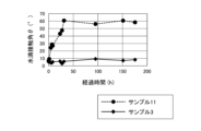
- 1 is a graph showing the change over time in the water droplet contact angle ⁇ when a hydrophilic glass according to one embodiment of the present invention (sample 3) and a comparative glass (sample 11) are held in an environment containing organic substances (DOP; dioctyl phthalate and DBP; dibutyl phthalate) present in the air.
- DOP organic substances
- the hydrophilicity can disappear after a certain period of continued use.
- hydrophilic glass is constructed by attaching a hydrophilic film to a glass substrate, the hydrophilicity will be lost if the hydrophilic film is peeled off. Therefore, conventional hydrophilic glass has the problem that it is difficult to maintain its hydrophilicity over a long period of time.
- one embodiment of the present invention provides a method for producing hydrophilic glass, comprising the steps of: (1) treating a first surface of a glass substrate by a gas etching process using hydrogen fluoride gas or a plasma etching process using CF4 gas; (2) cleaning the first surface of the glass substrate with an acid; A method is provided.
- a fluoride layer is formed on the first surface of the glass substrate in step (1), and this fluoride layer is removed in step (2).
- the surface of the glass substrate from which the fluoride layer has been removed has fine irregularities on the order of nanometers. As a result, after step (2), a hydrophilic irregular surface can be formed on the first surface of the glass substrate.
- the uneven surface that exhibits hydrophilicity is different from conventional hydrophilic surfaces formed by attaching a hydrophilic film to the surface of a glass substrate, and from hydrophilic surfaces formed by depositing a hydrophilic membrane on the surface of a glass substrate. That is, in the hydrophilic glass according to one embodiment of the present invention, the uneven surface extends from the bulk of the glass substrate and is integrally formed with the glass substrate.
- the uneven surface formed by one embodiment of the present invention has the characteristic of being less prone to peeling.
- hydrophilic glass produced according to one embodiment of the present invention to maintain its hydrophilic properties for a long period of time.
- the size of the fluoride particles formed can be adjusted by controlling the processing conditions in step (1), and as a result, after step (2), a rough surface with the desired unevenness can be obtained relatively easily.
- FIG. 1 shows an example of a flow chart for a method of producing hydrophilic glass according to one embodiment of the present invention.
- a method for producing hydrophilic glass according to one embodiment of the present invention includes the following steps: (1) A step of treating a first surface of a glass substrate by a gas etching process using hydrogen fluoride gas or a plasma etching process using CF4 gas (step S110); (2) acid-cleaning the first surface of the glass substrate (step S120); has.
- Step S110 First, a glass substrate to be processed is prepared.
- the shape and composition of the glass substrate are not particularly limited.
- the glass substrate may be made of, for example, soda-lime glass, alkali-free glass, aluminosilicate glass, or quartz glass.
- the glass substrate may have a thickness of, for example, 0.5 mm to 10 mm.
- the glass substrate has a first surface and a second surface that face each other. In the following description, as an example, a case in which the first surface of the glass substrate is to be treated will be described.
- etching process a gas etching process or a plasma etching process
- the etching process includes either a gas etching process using hydrogen fluoride gas (hereinafter simply referred to as “gas processing”) or a plasma etching process using CF4 gas (hereinafter simply referred to as “plasma processing”). Examples of each process will be described below.
- the glass substrate is placed in a processing chamber.
- the inside of the processing chamber may be heated.
- the heating temperature is, for example, in the range of 250° C. to 650° C.
- the process gas may contain a carrier gas such as argon or nitrogen.
- the concentration of hydrogen fluoride gas contained in the process gas is not particularly limited, but is, for example, in the range of 0.1 vol% to 10 vol%.
- the process gas etches the first surface of the glass substrate, forming fluoride on the first surface.
- the plasma generating device may be an atmospheric pressure plasma device that generates plasma at atmospheric pressure.
- Step S120 The glass substrate is then subjected to an acid cleaning process, which removes the fluoride formed in step S110 from the first surface.
- the acid used in the cleaning process is not particularly limited as long as it can properly remove fluoride.
- the acid may include, for example, at least one of hydrochloric acid, sulfuric acid, nitric acid, and acetic acid.
- An acidic detergent may also be used.
- the resulting uneven surface has a "specific surface area" in the range of 1.15 to 2.00.
- specific surface area refers to the ratio of the actual surface area to the projected area (i.e., apparent area) of the target part.
- the “specific surface area” is preferably in the range of 1.18 to 1.60.
- the difference between the maximum height and the minimum height (hereinafter referred to as the "unevenness difference ⁇ H") is, for example, 100 nm or less. It is preferable that the unevenness difference ⁇ H is in the range of 20 nm to 80 nm.
- the uneven surface having these characteristics causes hydrophilicity to appear on the first surface side of the glass substrate.
- the water droplet contact angle ⁇ on the uneven surface of the glass substrate is, for example, in the range of 0° to 10°.
- the water droplet contact angle ⁇ may also be in the range of 3° to 8°.
- the uneven surface obtained by the first method is different from the surface of a conventional applied hydrophilic film or the surface of a formed hydrophilic film, in that it extends from the bulk of the glass substrate and is formed integrally with the glass substrate. For this reason, problems such as peeling are unlikely to occur with the uneven surface. As a result, with the first method, the first surface of the glass substrate can continue to exhibit hydrophilicity for a long period of time.
- the water droplet contact angle ⁇ on an uneven surface can still be less than 10° even after being kept in the air for one month.
- FIG. 2 shows a schematic perspective view of a hydrophilic glass (hereinafter referred to as "first glass”) according to one embodiment of the present invention.
- the first glass 100 has a glass substrate 110 having a first surface 112 and a second surface 114 facing each other.
- the composition of the glass substrate 110 is not particularly limited.
- the glass substrate 110 may be composed of, for example, soda-lime glass, alkali-free glass, aluminosilicate glass, or quartz glass.
- the glass substrate 110 has a rectangular first surface 112 and a rectangular second surface 114.
- the shapes of the first surface 112 and the second surface 114 of the glass substrate 110 are not particularly limited.
- the first surface 112 and the second surface 114 may be circular or elliptical, or may be polygonal.
- the thickness of the glass substrate 110 is not particularly limited.
- the thickness of the glass substrate 110 may be in the range of 0.5 mm to 50 mm, for example.
- the first glass 100 has an uneven surface 120 at least on the side of the first surface 112 of the glass substrate 110.
- the uneven surface 120 may be the entire first surface 112 or a part of the first surface 112.
- the first glass 100 may also have an uneven surface on the side of the second surface 114 of the glass substrate 110.
- the textured surface 120 is not a surface composed of a separate "phase" that has an interface with the bulk of the glass substrate 110, such as a film applied to the first surface 112 of the glass substrate 110 and/or a film deposited on the first surface 112. That is, the textured surface 120 extends from the bulk of the glass substrate 110 and is integrally formed with the bulk.
- the uneven surface 120 is It is characterized in that (i) the specific surface area is in the range of 1.15 to 2.00, and (ii) the difference between the maximum height and the minimum height (that is, the unevenness difference ⁇ H) is 100 nm or less.
- the uneven surface 120 of the first glass 100 has hydrophilic properties.
- the water droplet contact angle ⁇ on the uneven surface 120 is 10° or less.
- the uneven surface 120 of the first glass 100 extends from the bulk of the glass substrate 110 and is integrally formed with the bulk. Therefore, the first glass 100 can significantly avoid the problem of the film and/or membrane peeling off during use and the loss of hydrophilicity.
- the water droplet contact angle ⁇ of the uneven surface 120 can be maintained at 10° or less even after being left in the air for more than one month.
- the first glass 100 having these characteristics can be manufactured by a method for manufacturing hydrophilic glass according to one embodiment of the present invention, such as the first method described above. That is, the first glass 100 can be obtained through the etching process and acid washing process described above.
- a fluorine-based gas or plasma is used to etch the glass substrate. For this reason, even after acid cleaning, a small amount of fluorine remains on the uneven surface.
- the first glass 100 may be characterized in that, when the fluorine concentration in the uneven surface 120 is F1 and the fluorine concentration in the bulk of the glass substrate 110 is F2, the difference between F1 and F2 (F1-F2) is 0.5 at% or more and 10 at% or less. In particular, it is preferable that the difference (F1-F2) is in the range of 1.0 at% to 4.0 at%.
- bulk fluorine concentration of the glass substrate means the fluorine concentration at the center of the thickness of the glass substrate.
- the unevenness of the uneven surface 120 of the first glass 100 is extremely small, on the order of nanometers. Therefore, the first glass 100 may be characterized by a haze of 0.2 or less. Such a first glass 100 can be applied to components that need to be "transparent.”
- Examples 1 to 4 are examples, and Example 11 is a comparative example.
- Example 1 A glass having an uneven surface was produced by the following method.
- the glass substrate was made of soda lime glass and had dimensions of 50 mm length x 50 mm width x 1.0 mm thickness.
- a plasma treatment device equipped with a nozzle head was used.
- the nozzle head has a double-tube structure with a central flow path and an annular flow path surrounding it.
- Argon gas (300 sccm) was supplied to the central passage, and a mixed gas of argon gas (1000 sccm) and CF 4 gas (150 sccm) was supplied to the annular passage.
- the glass substrate was fixed to a holder so that the first surface of the glass substrate faced upward, and the nozzle head was placed on top of the glass substrate.
- the distance between the glass substrate and the nozzle head was 24 mm.
- the plasma power was 150 W.
- the glass substrate was heated to 500°C, plasma was sprayed from the nozzle head, and the nozzle head was scanned in one direction (+X direction) across the glass substrate.
- the nozzle head was then moved approximately 2 mm in the direction perpendicular to the X direction (Y direction) (i.e., a pitch of 2 mm), and the nozzle head was similarly scanned in one direction (-X direction) across the glass substrate.
- This back and forth scanning was repeated to perform plasma treatment on the entire first surface of the glass substrate.
- the obtained glass substrate was subjected to an acid cleaning process.
- Hydrochloric acid was used as the acid, and the glass substrate was cleaned at room temperature.
- Example 1 glass was obtained that had an uneven surface on the first surface side.
- the obtained glass is called "Sample 1.”
- Example 2 A glass substrate having an uneven surface was produced in the same manner as in Example 1. However, in this Example 2, the glass substrate was not heated during the plasma treatment.
- Example 2 After the acid cleaning process, glass with an uneven surface was obtained. The resulting glass is called "Sample 2.”
- Example 3 A glass having an uneven surface was produced in the same manner as in Example 1. However, in this Example 3, a gas treatment was carried out as the etching treatment instead of a plasma treatment.
- the glass substrate was placed horizontally in a reactor and heated to 650°C. In this state, a processing gas was supplied to the upper surface (first surface) of the glass substrate to etch the first surface.
- a mixture of nitrogen and HF gas was used as the processing gas.
- the HF gas concentration was 10 vol%.
- the processing time was 8 seconds.
- Example 3 After the acid cleaning process, glass with an uneven surface was obtained. The resulting glass is called "Sample 3.”
- Example 4 A glass having an uneven surface was produced in the same manner as in Example 3. However, in this Example 4, the temperature of the glass substrate during the gas treatment was set to 500° C., and the treatment time was set to 5 seconds.
- Example 4 After the acid cleaning process, glass with an uneven surface was obtained. The resulting glass is called "Sample 4.”
- Example 11 The glass substrate used in Example 1 was simply washed with water to obtain “Sample 11.”
- Haze Measurement Haze measurements were carried out on each sample using a haze meter (HM-150L2; Murakami Color Research Laboratory) in accordance with JIS K 7136.
- the specific surface area of the first surface of each sample was measured using an AFM (Dimension Icon; Bruker).
- the contact angle of each sample was also measured again after a specified period of time had elapsed.
- FIG. 3 to 6 show examples of the surface morphology of the uneven surface in Samples 1 to 4, respectively.
- Figs. 7 to 10 show examples of the cross-sectional morphology of the uneven surface in Samples 1 to 4, respectively.
- Figure 11 shows the change over time in the water droplet contact angle ⁇ measured for Sample 1 and Sample 11.
- Figure 12 shows the change over time in the water droplet contact angle ⁇ measured for Sample 3 and Sample 11.
- Figure 11 shows the change in the water droplet contact angle ⁇ when the sample is kept in an air environment, with the horizontal axis representing the number of days.
- Figure 12 shows the change in the water droplet contact angle ⁇ when the sample is kept in a simulated exhaust gas environment, with the horizontal axis representing time.
- (Aspect 1) A method for producing hydrophilic glass, comprising the steps of: (1) treating a first surface of a glass substrate by a gas etching process using hydrogen fluoride gas or a plasma etching process using CF4 gas; (2) cleaning the first surface of the glass substrate with an acid; method.
- a hydrophilic glass a glass substrate having a first surface and a second surface opposed to each other; the first surface has a ratio of a surface area to a projected area of a target portion in the range of 1.15 to 2.00, and has an uneven surface with a difference between a maximum height and a minimum height of 100 nm or less; the textured surface extends from and is integrally formed with a bulk of the glass substrate; A hydrophilic glass having a haze of 0.2 or less.
Landscapes
- Chemical & Material Sciences (AREA)
- Life Sciences & Earth Sciences (AREA)
- Engineering & Computer Science (AREA)
- Chemical Kinetics & Catalysis (AREA)
- General Chemical & Material Sciences (AREA)
- Geochemistry & Mineralogy (AREA)
- Materials Engineering (AREA)
- Organic Chemistry (AREA)
- Surface Treatment Of Glass (AREA)
Priority Applications (1)
| Application Number | Priority Date | Filing Date | Title |
|---|---|---|---|
| JP2025537687A JPWO2025027994A1 (https=) | 2023-07-31 | 2024-05-27 |
Applications Claiming Priority (2)
| Application Number | Priority Date | Filing Date | Title |
|---|---|---|---|
| JP2023-124300 | 2023-07-31 | ||
| JP2023124300 | 2023-07-31 |
Publications (1)
| Publication Number | Publication Date |
|---|---|
| WO2025027994A1 true WO2025027994A1 (ja) | 2025-02-06 |
Family
ID=94395047
Family Applications (1)
| Application Number | Title | Priority Date | Filing Date |
|---|---|---|---|
| PCT/JP2024/019337 Pending WO2025027994A1 (ja) | 2023-07-31 | 2024-05-27 | 親水性ガラスを製造する方法および親水性ガラス |
Country Status (2)
| Country | Link |
|---|---|
| JP (1) | JPWO2025027994A1 (https=) |
| WO (1) | WO2025027994A1 (https=) |
Citations (3)
| Publication number | Priority date | Publication date | Assignee | Title |
|---|---|---|---|---|
| JP2014080333A (ja) * | 2012-10-17 | 2014-05-08 | Asahi Glass Co Ltd | 表面処理されたガラス基体の製造方法 |
| WO2014123089A1 (ja) * | 2013-02-07 | 2014-08-14 | 旭硝子株式会社 | ガラス製造方法 |
| JP2020523277A (ja) * | 2017-06-16 | 2020-08-06 | コーニング インコーポレイテッド | ガラス基板の表面を処理する方法 |
-
2024
- 2024-05-27 JP JP2025537687A patent/JPWO2025027994A1/ja active Pending
- 2024-05-27 WO PCT/JP2024/019337 patent/WO2025027994A1/ja active Pending
Patent Citations (3)
| Publication number | Priority date | Publication date | Assignee | Title |
|---|---|---|---|---|
| JP2014080333A (ja) * | 2012-10-17 | 2014-05-08 | Asahi Glass Co Ltd | 表面処理されたガラス基体の製造方法 |
| WO2014123089A1 (ja) * | 2013-02-07 | 2014-08-14 | 旭硝子株式会社 | ガラス製造方法 |
| JP2020523277A (ja) * | 2017-06-16 | 2020-08-06 | コーニング インコーポレイテッド | ガラス基板の表面を処理する方法 |
Also Published As
| Publication number | Publication date |
|---|---|
| JPWO2025027994A1 (https=) | 2025-02-06 |
Similar Documents
| Publication | Publication Date | Title |
|---|---|---|
| JP6706626B2 (ja) | フッ化アニールした膜でコーティングした物品 | |
| EP2065736B1 (en) | Anti-reflection structure body, method of producing the same and method of producing optical member | |
| CN116695048A (zh) | 钇基喷涂涂层和制造方法 | |
| JP7700794B2 (ja) | 耐食性部材 | |
| CN104201095A (zh) | 一种晶边刻蚀工艺 | |
| CN114262160B (zh) | 防眩光玻璃及其制备方法 | |
| CN107949901B (zh) | 利用等离子体蚀刻的防反射表面的制造方法及形成防反射表面的基板 | |
| WO2014061615A1 (ja) | 反射防止性を有するガラスの製造方法および反射防止性を有するガラス | |
| JP2009054984A (ja) | 成膜装置部品及びその製造方法 | |
| WO2012020295A1 (en) | Optical elements having long-lasting hydrophilic and anti-fog properties and method for their preparation | |
| WO2025027994A1 (ja) | 親水性ガラスを製造する方法および親水性ガラス | |
| WO2010005019A1 (ja) | 無機薄膜及びその製造方法、並びにガラス | |
| WO2011027872A1 (ja) | 無機構造物及びその製造方法、並びに無機薄膜の製造方法 | |
| KR20160016136A (ko) | 화학기상증착용 쿼츠 지그의 표면 처리 방법, 쿼츠 지그의 표면 처리용 조성물 및 그에 의해 제작된 쿼츠 지그 | |
| KR20230107643A (ko) | 내균열성 플루오로-어닐링된 필름으로 코팅된 물품 및 제조 방법 | |
| WO2024190771A1 (ja) | 積層部材及びその製造方法、並びに積層用基材 | |
| TWI668320B (zh) | 提高抗汙膜之附著力的方法 | |
| KR102272710B1 (ko) | 중공 나노 기둥이 구비된 유리의 제조방법 및 이를 이용하여 제조된 중공 나노 기둥이 구비된 유리 | |
| JP7819747B2 (ja) | ガラス部材の製造方法 | |
| TW202126599A (zh) | 石英玻璃之製造方法 | |
| EP4491595A1 (en) | Water-repellent glass | |
| JP2004143583A (ja) | 石英ガラス部品及びその製造方法並びにそれを用いた装置 | |
| TWI700257B (zh) | 具隔熱與自潔之玻璃及其製造方法 | |
| US11994651B2 (en) | Anti-reflective transparent oleophobic surfaces and methods of manufacturing thereof | |
| JP2001048591A (ja) | 表面撥水性ガラス及びその製造方法 |
Legal Events
| Date | Code | Title | Description |
|---|---|---|---|
| 121 | Ep: the epo has been informed by wipo that ep was designated in this application |
Ref document number: 24848655 Country of ref document: EP Kind code of ref document: A1 |
|
| ENP | Entry into the national phase |
Ref document number: 2025537687 Country of ref document: JP Kind code of ref document: A |
|
| WWE | Wipo information: entry into national phase |
Ref document number: 2025537687 Country of ref document: JP |
|
| NENP | Non-entry into the national phase |
Ref country code: DE |