WO2025027862A1 - コア片、ステータコア、ステータ、アキシャルギャップモータ、コア片製造装置、及びコア片製造方法 - Google Patents
コア片、ステータコア、ステータ、アキシャルギャップモータ、コア片製造装置、及びコア片製造方法 Download PDFInfo
- Publication number
- WO2025027862A1 WO2025027862A1 PCT/JP2023/028475 JP2023028475W WO2025027862A1 WO 2025027862 A1 WO2025027862 A1 WO 2025027862A1 JP 2023028475 W JP2023028475 W JP 2023028475W WO 2025027862 A1 WO2025027862 A1 WO 2025027862A1
- Authority
- WO
- WIPO (PCT)
- Prior art keywords
- core piece
- lower punch
- teeth
- punch
- flange
- Prior art date
- Legal status (The legal status is an assumption and is not a legal conclusion. Google has not performed a legal analysis and makes no representation as to the accuracy of the status listed.)
- Pending
Links
Images















Classifications
-
- H—ELECTRICITY
- H02—GENERATION; CONVERSION OR DISTRIBUTION OF ELECTRIC POWER
- H02K—DYNAMO-ELECTRIC MACHINES
- H02K1/00—Details of the magnetic circuit
- H02K1/02—Details of the magnetic circuit characterised by the magnetic material
-
- H—ELECTRICITY
- H02—GENERATION; CONVERSION OR DISTRIBUTION OF ELECTRIC POWER
- H02K—DYNAMO-ELECTRIC MACHINES
- H02K1/00—Details of the magnetic circuit
- H02K1/06—Details of the magnetic circuit characterised by the shape, form or construction
- H02K1/12—Stationary parts of the magnetic circuit
- H02K1/18—Means for mounting or fastening magnetic stationary parts on to, or to, the stator structures
-
- H—ELECTRICITY
- H02—GENERATION; CONVERSION OR DISTRIBUTION OF ELECTRIC POWER
- H02K—DYNAMO-ELECTRIC MACHINES
- H02K15/00—Processes or apparatus specially adapted for manufacturing, assembling, maintaining or repairing of dynamo-electric machines
- H02K15/02—Processes or apparatus specially adapted for manufacturing, assembling, maintaining or repairing of dynamo-electric machines of stator or rotor bodies
-
- H—ELECTRICITY
- H02—GENERATION; CONVERSION OR DISTRIBUTION OF ELECTRIC POWER
- H02K—DYNAMO-ELECTRIC MACHINES
- H02K21/00—Synchronous motors having permanent magnets; Synchronous generators having permanent magnets
- H02K21/12—Synchronous motors having permanent magnets; Synchronous generators having permanent magnets with stationary armatures and rotating magnets
- H02K21/24—Synchronous motors having permanent magnets; Synchronous generators having permanent magnets with stationary armatures and rotating magnets with magnets axially facing the armatures, e.g. hub-type cycle dynamos
Definitions
- the present invention relates to a core piece of a stator core of an axial gap motor, a stator core of an axial gap motor, a stator of an axial gap motor, an axial gap motor, a core piece manufacturing device, and a core piece manufacturing method.
- Patent Document 1 describes a core piece that constitutes a stator core of an axial gap motor.
- This core piece is a powder compact, and includes a columnar first member (teeth portion) extending in the axial direction of the stator core, a plate-shaped second member (first flange portion) provided on the first end side of the first member in the axial direction, and a plate-shaped third member (second flange portion) provided on the second end side of the first member in the axial direction.
- Each of the first member, second member, and third member has an outer peripheral surface disposed on the outer peripheral side of the stator core, an inner peripheral surface disposed on the inner peripheral side of the stator core, and a first side surface and a second side surface connected to the outer peripheral surface and the inner peripheral surface.
- the end of the first side surface on the outer peripheral surface side and the end of the second side surface on the outer peripheral surface side are parallel to each other in each of the first member, second member, and third member, and the end of the first side surface on the inner peripheral surface side and the end of the second side surface on the inner peripheral surface side are parallel to each other.
- the present disclosure therefore aims to provide a core piece, a stator core, a stator, an axial gap motor, a core piece manufacturing device, and a core piece manufacturing method that can increase magnetic flux density.
- the core piece according to the present disclosure is a core piece of a stator core of an axial gap motor, formed by pressing soft magnetic powder coated with an insulating material, and includes a teeth portion having a peripheral surface extending in a first direction around which a winding is wound, a first flange portion connected to one end of the teeth portion in the first direction and protruding from the teeth portion in a direction perpendicular to the first direction, and a second flange portion connected to an end of the teeth portion opposite the first flange portion in the first direction and protruding from the teeth portion in a direction perpendicular to the first direction, the peripheral surface of the teeth portion having an inner peripheral portion located on one side in a second direction perpendicular to the first direction, an outer peripheral portion located opposite the inner peripheral portion in the second direction, and a first side peripheral portion and a second side peripheral portion connected to the inner peripheral portion and the outer peripheral portion, and the first inner peripheral portion, which is the end of the first side peripheral portion on the inner peripheral portion side,
- the circumferential surface of the teeth around which the winding is wound has an inner circumference, an outer circumference, a first side circumference, and a second side circumference
- the first inner circumference end portion which is the end portion on the inner circumference side of the first side circumference
- moves toward the second inner circumference end portion which is the end portion on the inner circumference side of the second side circumference, as it moves toward the inner circumference. Therefore, when the winding is wound around the circumferential surface of the teeth, it is easy to align the winding with the first inner circumference end portion and the inner circumference. This makes it possible to suppress floating of the winding from the teeth near the connection portion between the first inner circumference end portion and the inner circumference, thereby increasing the magnetic flux density.
- the first inner periphery side end portion may be a curved surface that curves toward the second inner periphery side end portion.
- the first inner periphery side end portion is a curved surface that curves toward the second inner periphery side end portion, it becomes easier to align the winding with the first inner periphery side end portion and the inner periphery.
- the first inner circumferential side end portion may be an inclined surface that slopes toward the second inner circumferential side end portion.
- the first inner circumferential side end portion since the first inner circumferential side end portion is an inclined surface that slopes toward the second inner circumferential side end portion, the first inner circumferential side end portion can be easily formed.
- the second inner circumferential side end may be directed toward the first inner circumferential side end as it approaches the inner circumferential portion.
- the winding since the second inner circumferential side end is directed toward the first inner circumferential side end as it approaches the inner circumferential portion, when the winding is wound around the circumferential surface of the teeth, the winding can be easily aligned along the second inner circumferential side end and the inner circumferential portion. This makes it possible to suppress the winding from floating away from the teeth in the vicinity of the connection between the second inner circumferential side end and the inner circumferential portion, thereby further increasing the magnetic flux density.
- the second inner periphery side end portion may be a curved surface that curves toward the first inner periphery side end portion.
- the second inner periphery side end portion is a curved surface that curves toward the first inner periphery side end portion, it becomes easier to align the winding with the second inner periphery side end portion and the inner periphery.
- the second inner circumferential side end portion may be an inclined surface that slopes toward the first inner circumferential side end portion.
- the second inner circumferential side end portion since the second inner circumferential side end portion is an inclined surface that slopes toward the first inner circumferential side end portion, the second inner circumferential side end portion can be easily formed.
- the stator core according to the present disclosure is a stator core for an axial gap motor, and includes the core pieces described in any one of [1] to [6]. Since this stator core includes the above-mentioned core pieces, the magnetic flux density can be increased.
- the stator according to the present disclosure is a stator for an axial gap motor, and includes the stator core described in [7] and a winding wound around the core piece of the stator core. Since this stator has the stator core described above, the magnetic flux density can be increased.
- the axial gap motor according to the present disclosure includes the stator described in [8] and a rotor arranged to be rotatable relative to the stator. Since this axial gap motor has the stator described above, it is possible to increase the magnetic flux density.
- the core piece manufacturing apparatus is a core piece manufacturing apparatus for manufacturing a core piece as described in any one of [1] to [6], comprising: a die having a forming hole; an upper punch inserted into the forming hole from above; a first lower punch inserted into the forming hole from below; and a second lower punch inserted into the forming hole from below, wherein the upper punch has an upper pressing surface for teeth that forms a teeth portion of the core piece between itself and the first lower punch, and an upper pressing surface for a first flange portion and an upper pressing surface for a second flange portion that form a first flange portion and a second flange portion of the core piece between itself and the second lower punch,
- the punch has a lower pressing surface for the teeth that forms the teeth between itself and the upper punch
- the second lower punch has a lower pressing surface for the first flange and a lower pressing surface for the second flange that form the first flange and the second flange between itself and the upper punch, the upper pressing
- the upper punch has an upper pressing surface for the teeth which forms the teeth portion of the core piece between it and the first lower punch, and an upper pressing surface for the first flange portion and an upper pressing surface for the second flange portion which form the first and second flange portions of the core piece between it and the second lower punch
- the first lower punch has a lower pressing surface for the teeth which forms the teeth portion between it and the upper punch
- the second lower punch has a lower pressing surface for the first flange portion and a lower pressing surface for the second flange portion which form the first and second flange portions between it and the upper punch
- the upper pressing surface for the teeth of the upper punch has a shape corresponding to the outer periphery of the teeth portion
- the lower pressing surface for the teeth of the first lower punch has a bottom surface shaped relative to the inner periphery of the teeth portion, a first bottom surface shaped corresponding to the first inner periphery side end portion of the teeth portion, and a second bottom surface shaped corresponding to the second inner
- the above-mentioned core pieces can be compacted by inserting a first lower punch and a second lower punch into the forming hole of the die, supplying soft magnetic powder coated with an insulating material from above into the forming hole, inserting an upper punch into the forming hole, and pressing the soft magnetic powder with the upper punch and the first lower punch and second lower punch. This makes it possible to manufacture core pieces that can increase the magnetic flux density.
- the first lower punch has a first main lower punch and a first auxiliary lower punch that can move up and down relative to the first main lower punch, and the first main lower punch may have a part of the lower pressing surface for the teeth, and the first auxiliary lower punch may have the remaining part of the lower pressing surface for the teeth.
- the first lower punch has a first main lower punch that has a part of the lower pressing surface for the teeth, and a first auxiliary lower punch that has the remaining part of the lower pressing surface for the teeth and is movable up and down relative to the first main lower punch. Therefore, after the core piece is powder-compressed, the first auxiliary lower punch can be moved upward relative to the first main lower punch to easily extract the core piece from the first lower punch.
- the first main lower punch may have a first bottom surface and a portion of the bottom surface of the lower pressing surface for the teeth, and the first auxiliary lower punch may have the remaining portion of the bottom surface of the lower pressing surface for the teeth.
- the first main lower punch has a first bottom surface and a portion of the bottom surface of the lower pressing surface for the teeth, and the first auxiliary lower punch has the remaining portion of the bottom surface of the lower pressing surface for the teeth. Therefore, after the core piece has been powder-compressed, the first auxiliary lower punch can be moved upward relative to the first main lower punch to easily extract the core piece from the first lower punch.
- the core piece manufacturing method is a method for manufacturing a core piece of a stator core of an axial gap motor using a core piece manufacturing apparatus according to any one of [10] to [12], and includes a lower punch inserting step of inserting a first lower punch and a second lower punch into a forming hole of a die, a powder supplying step of supplying soft magnetic powder coated with an insulating material from above into the forming hole after the lower punch inserting step, a pressing step of inserting an upper punch into the forming hole after the powder supplying step, and pressing the soft magnetic powder supplied into the forming hole with the upper punch and the first lower punch and the second lower punch to form a core piece formed by pressing the soft magnetic powder, and an extraction step of extracting the core piece from the forming hole after the pressing step.
- the first lower punch and the second lower punch are inserted into the forming hole, soft magnetic powder coated with an insulating material is supplied from above into the forming hole, the upper punch is inserted into the forming hole, and the soft magnetic powder supplied to the forming hole is pressed by the upper punch and the first lower punch and the second lower punch, thereby compacting the above-mentioned core piece. Then, after the core piece has been compacted, it is removed from the forming hole, thereby producing a core piece that can increase the magnetic flux density.
- the upper punch and the second lower punch may be moved upward in the ejection step.
- the upper punch and the second lower punch are moved upward, so that the core piece can be easily ejected from the molding hole.
- the first lower punch has a first main lower punch having a part of the lower pressing surface for the teeth, and a first auxiliary lower punch having the remaining part of the lower pressing surface for the teeth and movable in the vertical direction relative to the first main lower punch, and in the ejection step, the upper punch may be moved upward and the first auxiliary lower punch may be moved upward relative to the first main lower punch.
- the upper punch after the core piece is powder-compressed, the upper punch may be moved upward and the first auxiliary lower punch may be moved upward relative to the first main lower punch, thereby ejecting the core piece from the first main lower punch and easily ejecting the core piece from the molding hole.
- the magnetic flux density can be increased.
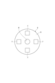
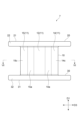
- FIG. 1 is a schematic cross-sectional view showing an axial gap motor according to an embodiment.
- FIG. 2 is a schematic diagram showing a stator core according to the embodiment.
- FIG. 3 is a perspective view showing a core piece according to the embodiment.
- FIG. 4 is a perspective view showing a core piece according to the embodiment.
- FIG. 5 is a front view showing a core piece according to the embodiment.
- FIG. 6 is a bottom view showing a core piece according to the embodiment.
- FIG. 7 is a cross-sectional view taken along line VII-VII shown in FIG.
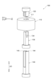
- FIG. 8 is an exploded perspective view showing the core piece manufacturing apparatus according to the first embodiment.
- FIG. 9 is a front view showing the core piece manufacturing apparatus according to the first embodiment.
- FIG. 10 is a side view showing the core piece manufacturing apparatus according to the first embodiment.
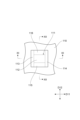
- FIG. 11 is a plan view showing a portion of the die.
- FIG. 12 is a cross-sectional view taken along line XII-XII shown in FIG.
- FIG. 13 is a cross-sectional view taken along line XIII-XIII shown in FIG.
- FIG. 14 is a perspective view showing the upper punch.
- FIG. 15 is a perspective view showing the first lower punch.
- FIG. 16 is a perspective view showing the first lower punch.
- FIG. 17 is a front view showing the first lower punch.
- FIG. 18 is a cross-sectional view showing the lower punch inserting step.
- FIG. 19 is a cross-sectional view showing the lower punch inserting step.
- FIG. 19 is a cross-sectional view showing the lower punch inserting step.
- FIG. 20 is a cross-sectional view showing the powder supplying step.
- FIG. 21 is a cross-sectional view showing the powder supplying process.
- FIG. 22 is a cross-sectional view showing the pressing process.
- FIG. 23 is a cross-sectional view showing the pressing process.
- FIG. 24 is a cross-sectional view showing the extraction process.
- FIG. 25 is a cross-sectional view showing the extraction process.
- FIG. 26 is an exploded perspective view showing a core piece manufacturing apparatus according to the second embodiment.
- FIG. 27 is a front view showing a core piece manufacturing apparatus according to the second embodiment.
- FIG. 28 is a side view showing a core piece manufacturing apparatus according to the second embodiment.
- FIG. 29 is a cross-sectional view showing the lower punch inserting step.
- FIG. 30 is a cross-sectional view showing the lower punch inserting step.
- FIG. 31 is a cross-sectional view showing the powder supplying process.
- FIG. 32 is a cross-sectional view showing the powder supplying process.
- FIG. 33 is a cross-sectional view showing the pressing process.
- FIG. 34 is a cross-sectional view showing the pressing process.
- FIG. 35 is a cross-sectional view showing the extraction process.
- FIG. 36 is a cross-sectional view showing the extraction process.
- FIG. 1 is a schematic cross-sectional view showing an axial gap motor according to an embodiment.
- the axial gap motor 1 according to this embodiment includes a stator 2, a rotor 3 arranged rotatably relative to the stator 2, and a shaft 4 fixed to the rotor 3.
- the stator 2 and the rotor 3 are arranged to be spaced apart in the axial direction of the shaft 4.
- FIG. 2 is a schematic diagram showing a stator according to an embodiment.
- a stator 2 according to this embodiment is a stator for an axial gap motor 1.
- the stator 2 includes a stator core 5 having a plurality of core pieces 7, and a winding 6 wound around each of the plurality of core pieces 7.
- the stator core 5 is a portion of the stator 2 excluding the winding 6.
- a shaft hole 8 through which the shaft 4 is inserted is formed in the center of the stator core 5.
- FIG. 3 is a perspective view showing a core piece according to the embodiment.
- Fig. 4 is a perspective view showing a core piece according to the embodiment.
- Fig. 5 is a front view showing a core piece according to the embodiment.
- Fig. 6 is a bottom view showing a core piece according to the embodiment.
- Fig. 7 is a cross-sectional view taken along line VII-VII shown in Fig. 6.
- the core piece 7 according to this embodiment is a core piece of the stator core 5 of the axial gap motor 1.
- the core piece 7 is a part that constitutes a part of the stator core 5 of the axial gap motor 1.
- the core piece 7 is a compact formed by pressing soft magnetic powder coated with an insulating material.
- the material of the soft magnetic powder is, for example, pure iron, iron silicon, or iron cobalt.
- the average particle size of the soft magnetic powder is, for example, 3 ⁇ m to 300 ⁇ m, 30 ⁇ m to 200 ⁇ m, or 50 ⁇ m to 150 ⁇ m.
- the material of the insulating material is, for example, an insulating coating containing phosphoric acid, silicone, or the like.
- the average particle size of the soft magnetic powder is measured using a robot shifter (model number: RPS-205) manufactured by Seishin Enterprise Co., Ltd.
- the core piece 7 has a teeth portion 10, a first flange portion 20, and a second flange portion 30.
- the teeth portion 10 extends in the first direction D1 and has a peripheral surface 11 around which the winding 6 (see FIG. 1) is wound.
- the teeth portion 10 extends in the first direction D1 in a columnar shape, and its side surface forms the peripheral surface 11.
- the first flange portion 20 is connected to one end of the teeth portion 10 in the first direction D1, and protrudes from the teeth portion 10 in a direction perpendicular to the first direction D1.
- the direction perpendicular to the first direction D1 is referred to as the second direction D2
- the direction perpendicular to the first direction D1 and the second direction D2 is referred to as the third direction D3.
- the first flange portion 20 protrudes from the teeth portion 10 when viewed from the first direction D1.
- the first flange portion 20 protrudes from one end of the teeth portion 10 in the first direction D1 in directions along the second direction D2 and the third direction D3.
- the first flange 20 has a first outer surface 21, which is the surface opposite the second flange 30 in the first direction D1, a first inner surface 22, which is the surface on the second flange 30 side in the first direction D1, a first lower end face 23, which is an end face on one side in the second direction D2, a first upper end face 24, which is an end face opposite the first lower end face 23 in the second direction D2, a first front end face 25, which is an end face on one side in the third direction D3, and a first rear end face 26, which is an end face opposite the first front end face 25 in the third direction D3.
- the first flange 20 is formed, for example, in a rectangular plate shape. That is, the first flange 20 is formed, for example, in a rectangular shape when viewed from the front, which is the viewing direction as seen from the first direction D1.
- the second flange portion 30 is connected to the end of the teeth portion 10 opposite the first flange portion 20 in the first direction D1, and protrudes from the teeth portion 10 in a direction perpendicular to the first direction D1.
- the second flange portion 30 protrudes from the teeth portion 10 when viewed from the first direction D1.
- the second flange portion 30 protrudes in directions along the second direction D2 and third direction D3 from the end of the teeth portion 10 opposite the first flange portion 20 in the first direction D1.
- the second flange portion 30 has a second outer surface 31, which is a surface opposite to the first flange portion 20 in the first direction D1, a second inner surface 32, which is a surface on the first flange portion 20 side in the first direction D1, a second lower end surface 33, which is an end surface on one side in the second direction D2, a second upper end surface 34, which is an end surface opposite to the second lower end surface 33 in the second direction D2, a second front end surface 35, which is an end surface on one side in the third direction D3, and a second rear end surface 36, which is an end surface opposite to the second front end surface 35 in the third direction D3.
- the direction of the second lower end surface 33 relative to the second upper end surface 34 in the second direction D2 is the same as the direction of the first lower end surface 23 relative to the first upper end surface 24 in the second direction D2.
- the direction of the second front end surface 35 relative to the second rear end surface 36 in the third direction D3 is the same as the direction of the first front end surface 25 relative to the first rear end surface 26 in the third direction D3.
- the second flange 30 is formed, for example, in a rectangular plate shape. That is, the second flange 30 is formed, for example, in a rectangular shape when viewed from the front, which is the viewing direction as seen from the first direction D1.
- the circumferential surface 11 of the teeth portion 10 has an inner circumferential portion 12, an outer circumferential portion 13, a first side circumferential portion 14, and a second side circumferential portion 15.
- the inner circumferential portion 12, the outer circumferential portion 13, the first side circumferential portion 14, and the second side circumferential portion 15 form the entire circumference of the circumferential surface 11.
- the inner circumferential portion 12 is located on one side in the second direction D2.
- the side in the second direction D2 on which the inner circumferential portion 12 is located refers to the center side of the stator core 5, that is, the side of the shaft hole 8 of the stator core 5.
- the inner circumferential portion 12 is formed, for example, in a flat shape and extends in a direction along the first direction D1 and the third direction D3.
- the outer peripheral portion 13 is located on the opposite side of the inner peripheral portion 12 in the second direction D2.
- the opposite side of the inner peripheral portion 12 in the second direction D2 where the outer peripheral portion 13 is located means the opposite side of the center of the stator core 5, that is, the opposite side of the shaft hole 8 of the stator core 5.
- the outer peripheral portion 13 is formed, for example, in a planar shape and extends in a direction along the first direction D1 and the third direction D3.
- the length of the outer peripheral portion 13 in the third direction D3 is longer than the length of the inner peripheral portion 12 in the third direction D3.
- the direction of the outer peripheral portion 13 relative to the inner peripheral portion 12 in the second direction D2 is the same as the direction of the second lower end face 33 relative to the second upper end face 34 in the second direction D2 and the direction of the first lower end face 23 relative to the first upper end face 24 in the second direction D2.
- the first side periphery 14 and the second side periphery 15 are connected to the inner periphery 12 and the outer periphery 13 so as to face each other. That is, the first side periphery 14 is connected to one edge of the inner periphery 12 in the third direction D3 and one edge of the outer periphery 13 in the third direction D3.
- the second side periphery 15 is connected to the edge of the inner periphery 12 opposite the first side periphery 14 in the third direction D3 and the edge of the outer periphery 13 opposite the first side periphery 14 in the third direction D3.
- the first side circumferential portion 14 has a first inner circumferential end portion 14a, a first outer circumferential end portion 14b, and a first central circumferential portion 14c.
- the first inner circumferential end portion 14a is the end portion of the first side circumferential portion 14 on the inner circumferential portion 12 side.
- the first outer circumferential end portion 14b is the end portion of the first side circumferential portion 14 on the outer circumferential portion 13 side.
- the first central circumferential portion 14c is disposed between the first inner circumferential end portion 14a and the first outer circumferential end portion 14b, and is a portion that is connected to the first inner circumferential end portion 14a and the first outer circumferential end portion 14b.
- the second side periphery 15 has a second inner periphery end 15a, a second outer periphery end 15b, and a second central periphery 15c.
- the second inner periphery end 15a is the end of the second side periphery 15 on the inner periphery 12 side.
- the second outer periphery end 15b is the end of the second side periphery 15 on the outer periphery 13 side.
- the second central periphery 15c is located between the second inner periphery end 15a and the second outer periphery end 15b, and is a portion that is connected to the second inner periphery end 15a and the second outer periphery end 15b.
- the first inner circumference side end portion 14a and the second inner circumference side end portion 15a are not formed parallel to each other, but are formed so as to approach each other toward the inner circumference portion 12.
- the first inner circumferential end 14a is directed toward the second inner circumferential end 15a as it approaches the inner circumferential portion 12.
- the first inner circumferential end 14a may be a curved surface that curves toward the second inner circumferential end 15a, or may be an inclined surface that slopes toward the second inner circumferential portion 15. That is, the first inner circumferential end 14a may be formed as a curved surface that curves toward the second inner circumferential end 15a, so that it approaches the second inner circumferential end 15a as it approaches the inner circumferential portion 12.
- the first inner circumferential end 14a may be formed as an inclined surface that slopes toward the second inner circumferential end 15a with respect to the second direction D2, so that it approaches the second inner circumferential end 15a as it approaches the inner circumferential portion 12.
- the first inner circumferential end 14a may be formed, for example, in an arc shape.
- the drawing shows an example in which the first inner peripheral end portion 14a is formed in an arc shape.
- the second inner circumferential end portion 15a is directed toward the first inner circumferential end portion 14a as it approaches the inner circumferential portion 12.
- the second inner circumferential end portion 15a may be a curved surface that curves toward the first inner circumferential end portion 14a, or may be an inclined surface that inclines toward the first inner circumferential end portion 14a. That is, the second inner circumferential end portion 15a may be formed as a curved surface that curves toward the first inner circumferential end portion 14a, so as to be directed toward the first inner circumferential end portion 14a as it approaches the inner circumferential portion 12.
- the second inner circumferential end portion 15a may be formed as an inclined surface that inclines toward the first inner circumferential end portion 14a with respect to the second direction D2, so as to be directed toward the first inner circumferential end portion 14a as it approaches the inner circumferential portion 12.
- the second inner circumferential end portion 15a may be formed, for example, in an arc shape.
- the drawing shows an example in which the second inner peripheral end portion 15a is formed in an arc shape.
- the first outer peripheral end 14b and the second outer peripheral end 15b extend in the first direction D1 and the second direction D2, and are formed parallel to each other. In other words, the first outer peripheral end 14b and the second outer peripheral end 15b form parallel surfaces.
- the first central side peripheral portion 14c and the second central side peripheral portion 15c are not formed parallel to each other, but are formed so as to approach each other toward the inner peripheral portion 12.
- the first central side peripheral portion 14c approaches the second central side peripheral portion 15c as it approaches the inner peripheral portion 12.
- the first central side peripheral portion 14c is, for example, an inclined surface that inclines toward the second central side peripheral portion 15c with respect to the second direction D2 as it approaches the inner peripheral portion 12.
- the first inner peripheral side end portion 14a and the first central side peripheral portion 14c may be inclined surfaces that incline at the same angle with respect to the second direction D2.
- the second central side peripheral portion 15c approaches the first central side peripheral portion 14c as it approaches the inner peripheral portion 12.
- the second central side peripheral portion 15c is, for example, an inclined surface that inclines toward the first central side peripheral portion 14c with respect to the second direction D2 as it approaches the inner peripheral portion 12.
- the second inner peripheral side end portion 15a and the second central side peripheral portion 15c may be inclined surfaces that incline at the same angle with respect to the second direction D2.
- connection portion between the teeth portion 10 and the first flange portion 20 is formed in a curved shape.
- the end of the teeth portion 10 on the second flange portion 30 side gradually widens as it reaches the second flange portion 30.
- the connection portion between the teeth portion 10 and the second flange portion 30 is formed in a curved shape.
- the circumferential surface 11 of the teeth 10 around which the winding 6 is wound has an inner circumferential portion 12, an outer circumferential portion 13, a first side circumferential portion 14, and a second side circumferential portion 15, and the first inner circumferential end portion 14a, which is the end portion of the first side circumferential portion 14 on the inner circumferential portion 12 side, moves toward the second inner circumferential end portion 15a, which is the end portion of the second side circumferential portion 15 on the inner circumferential portion 12 side, as it moves toward the inner circumferential portion 12.
- the winding 6 when the winding 6 is wound around the circumferential surface 11 of the teeth 10, the winding 6 can be easily aligned with the first inner circumferential end portion 14a and the inner circumferential portion 12. This makes it possible to suppress the winding 6 from floating from the teeth 10 in the vicinity of the connection portion between the first inner circumferential end portion 14a and the inner circumferential portion 12, thereby increasing the magnetic flux density.
- the first inner periphery side end portion 14a is a curved surface that curves toward the second inner periphery side end portion 15a, making it easier to align the winding 6 with the first inner periphery side end portion 14a and the inner periphery portion 12.
- the first inner circumference side end 14a is an inclined surface that slopes toward the second inner circumference side end 15a, making it easy to form the first inner circumference side end 14a.
- the second inner circumferential end portion 15a approaches the first inner circumferential end portion 14a as it approaches the inner circumferential portion 12, so when the winding 6 is wound around the circumferential surface 11 of the teeth portion 10, the winding 6 can be easily aligned along the second inner circumferential end portion 15a and the inner circumferential portion 12. This makes it possible to suppress the winding 6 from floating away from the teeth portion 10 in the vicinity of the connection between the second inner circumferential end portion 15a and the inner circumferential portion 12, thereby further increasing the magnetic flux density.
- the second inner periphery side end portion 15a is a curved surface that curves toward the first inner periphery side end portion 14a, making it easier to align the winding 6 with the second inner periphery side end portion 15a and the inner periphery portion 12.
- the second inner circumference side end 15a is an inclined surface that is inclined toward the first inner circumference side end 14a, so that the second inner circumference side end 15a can be easily formed.
- the stator core 5 according to this embodiment includes the above-mentioned core pieces 7, which allows for increased magnetic flux density.
- the stator 2 according to this embodiment has the stator core 5 described above, which allows for increased magnetic flux density.
- the axial gap motor 1 has the stator 2 described above, which allows for increased magnetic flux density.
- the core piece manufacturing apparatus is a powder compaction apparatus for manufacturing the core pieces 7.
- Figure 8 is an exploded perspective view showing a core piece manufacturing apparatus according to the first embodiment.
- Figure 9 is a front view showing a core piece manufacturing apparatus according to the first embodiment.
- Figure 10 is a side view showing a core piece manufacturing apparatus according to the first embodiment.
- the core piece manufacturing apparatus 100 according to this embodiment comprises a die 110 having a forming hole 111, an upper punch 120 inserted into the forming hole 111 from above U, a first lower punch 130 inserted into the forming hole 111 from below D, and a second lower punch 140 inserted into the forming hole 111 from below D.
- FIG. 11 is a plan view showing a portion of the die.
- FIG. 12 is a cross-sectional view taken along line XII-XII in FIG. 11.
- FIG. 13 is a cross-sectional view taken along line XIII-XIII in FIG. 11.
- the die 110 is a mold for compacting the core piece 7.
- the die 110 is formed with a molding hole 111 for forming the core piece 7.
- the molding hole 111 passes through the die 110 in the up-down direction UD.
- the molding hole 111 has the same cross section throughout the entire area in the up-down direction UD.
- the molding hole 111 is composed of a teeth space 112 for forming the teeth 10 of the core piece 7, a first flange space 113 for forming the first flange 20 of the core piece 7, a second flange space 114 for forming the second flange 30 of the core piece 7, and a first punch space 115 and a second punch space 116 adjacent to the teeth space 112, the first flange space 113, and the second flange space 114.
- Each of the teeth space 112, the first flange space 113, the second flange space 114, the first punch space 115, and the second punch space 116 penetrates the die 110 in the vertical direction UD and has the same cross section throughout the entire area of the vertical direction UD.
- the directions perpendicular to each other in the horizontal direction are the first horizontal direction D11 and the second horizontal direction D12.
- the first flange space 113 and the second flange space 114 are arranged to face each other in the first horizontal direction D11.
- the teeth space 112 is arranged in the center in the second horizontal direction D12 between the first flange space 113 and the second flange space 114 in the first horizontal direction D11.
- the first punch space 115 is arranged on one side of the teeth space 112 in the second horizontal direction D12 between the first flange space 113 and the second flange space 114 in the first horizontal direction D11.
- the second punch space 116 is arranged on the opposite side of the first punch space 115 of the teeth space 112 in the second horizontal direction D12 between the first flange space 113 and the second flange space 114 in the first horizontal direction D11.
- Figure 14 is a perspective view showing the upper punch.
- the upper punch 120 is a punch that is inserted into the forming hole 111 from above U.
- the upper punch 120 is positioned above U of the forming hole 111 and is movable in the up-down direction UD.
- the upper punch 120 can be inserted into and removed from the forming hole 111 from above U of the die 110.
- the upper punch 120 has an upper pressing portion 121 for teeth arranged above the U of the space 112 for teeth in the forming hole 111, an upper pressing portion 122 for the first flange arranged above the U of the space 113 for the first flange in the forming hole 111, and an upper pressing portion 123 for the second flange arranged above the U of the space 114 for the second flange in the forming hole 111.
- the portion between the upper pressing portion 122 for the first flange and the upper pressing portion 123 for the second flange other than the upper pressing portion 121 for teeth is cut out so that the upper punch 120 cannot be inserted into the space 115 for the first punch and the space 116 for the second punch.
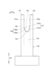
- the lower surface of the upper pressing portion for teeth 121 is formed with an upper pressing surface for teeth 124 which forms the teeth portion 10 of the core piece 7 between it and the first lower punch 130.
- the lower surface of the upper pressing surface for first flange 125 is formed with an upper pressing surface for first flange 125 which forms the first flange portion 20 of the core piece 7 between it and the second lower punch 140.
- the lower surface of the upper pressing portion for second flange 123 is formed with an upper pressing surface for second flange 126 which forms the second flange portion 30 of the core piece 7 between it and the second lower punch 140.
- the upper pressing surface 124 for the teeth is formed by a part of the lower surface of the upper punch 120 and is inserted into the space 112 for the teeth in the forming hole 111.
- the upper pressing surface 124 for the teeth has a shape corresponding to the outer periphery 13 of the teeth portion 10.
- the upper pressing surface 125 for the first flange is formed by a part of the lower surface of the upper punch 120, and is inserted into the space 113 for the first flange in the forming hole 111.
- the upper pressing surface 125 for the first flange has a shape corresponding to the first upper end surface 24 of the first flange 20.
- the upper pressing surface 125 for the first flange is located above the upper pressing surface 124 for the teeth in the vertical direction UD.
- the upper pressing surface 126 for the second flange is formed by a part of the lower surface of the upper punch 120, and is inserted into the space 114 for the second flange in the forming hole 111.
- the upper pressing surface 126 for the second flange has a shape corresponding to the second upper end surface 34 of the second flange 30.
- the upper pressing surface 126 for the second flange is located above the upper pressing surface 124 for the teeth in the vertical direction UD.
- Figure 15 is a perspective view of the first lower punch.
- Figure 16 is a perspective view of the first lower punch.
- Figure 17 is a front view of the first lower punch.
- the first lower punch 130 is a punch that is inserted into the forming hole 111 from below D.
- the first lower punch 130 is positioned below D of the forming hole 111 and is movable in the up and down direction UD.
- the first lower punch 130 is insertable into and removable from the forming hole 111 from below D of the die 110.
- the first lower punch 130 has a first mold portion 131 arranged below D of the first punch space 115 of the forming hole 111, a second mold portion 132 arranged below D of the second punch space 116 of the forming hole 111, and a lower tooth pressing portion 133 arranged below D of the teeth space 112 of the forming hole 111.
- the first lower punch 130 is formed in a U-shape that is open to the upper U.
- the first mold portion 131 and the second mold portion 132 face each other in the second horizontal direction D12 and are arranged so as to be spaced apart in the second horizontal direction D12.
- the lower pressing portion for teeth 133 is arranged between the lower portion of the first mold portion 131 and the lower portion of the second mold portion 132. In other words, the first mold portion 131 and the second mold portion 132 extend further upward U than the lower pressing portion for teeth 133.
- a space that is open to the upper U and the first horizontal direction D11 is formed between the first mold portion 131, the second mold portion 132, and the lower pressing portion for teeth 133.
- the upper surface of the lower pressing portion 133 for teeth is formed with a lower pressing surface 134 for teeth, which forms the teeth portion 10 of the core piece 7 between the upper punch 120 and the lower pressing surface 134 for teeth.
- the lower pressing surface 134 for teeth is formed by a part of the upper surface of the first lower punch 130 and is inserted into the space 112 for teeth of the forming hole 111.
- the lower pressing surface 134 for teeth has a bottom surface 135 having a shape corresponding to the inner periphery 12 of the teeth portion 10, a first side surface 136 having a shape corresponding to the first side periphery 14 of the teeth portion 10, and a second side surface 137 having a shape corresponding to the second side periphery 15 of the teeth portion 10.
- the end of the first side surface 136 on the bottom surface 135 side is a first side bottom surface 136a having a shape corresponding to the first inner periphery side end 14a of the first side periphery 14.
- the end of the second side surface 137 on the bottom surface 135 side is a second side bottom surface 137a having a shape corresponding to the second inner periphery side end 15a of the second side periphery 15.
- the bottom surface 135 is formed, for example, in a planar shape and extends in a direction along the first horizontal direction D11 and the second horizontal direction D12.
- First side bottom surface 136a and first side bottom surface 136a are not formed parallel to each other, but are formed so as to approach each other toward bottom surface 135.
- the first bottom surface 136a is directed toward the second bottom surface 137a as it approaches the bottom surface 135.
- the first bottom surface 136a may be a curved surface that curves toward the second bottom surface 137a, or may be an inclined surface that inclines toward the second bottom surface 137a. That is, the first bottom surface 136a may be formed as a curved surface that curves toward the second bottom surface 137a, so that it approaches the bottom surface 135.
- the first bottom surface 136a may also be formed as an inclined surface that inclines toward the second bottom surface 137a with respect to the up-down direction UD, so that it approaches the second bottom surface 137a as it approaches the bottom surface 135.
- the first bottom surface 136a may be formed, for example, in an arc shape.
- the drawings show a case in which the first bottom surface 136a is formed in an arc shape as an example.
- the second bottom surface 137a is directed toward the first bottom surface 136a as it approaches the bottom surface 135.
- the second bottom surface 137a may be a curved surface that curves toward the first bottom surface 136a, or may be an inclined surface that inclines toward the first bottom surface 136a. That is, the second bottom surface 137a may be formed as a curved surface that curves toward the first bottom surface 136a, so that it approaches the first bottom surface 136a as it approaches the bottom surface 135.
- the second bottom surface 137a may be formed as an inclined surface that inclines toward the first bottom surface 136a with respect to the up-down direction UD, so that it approaches the first bottom surface 136a as it approaches the bottom surface 135.
- the second bottom surface 137a may be formed, for example, in an arc shape.
- the drawings show a case in which the second bottom surface 137a is formed in an arc shape as an example.
- the portion 136b of the first side surface 136 other than the first bottom surface 136a forms the first central side peripheral portion 14c of the teeth portion 10.
- the portion 137b of the second side surface 137 other than the second bottom surface 137a forms the second central side peripheral portion 15c of the teeth portion 10.
- the portion 136b of the first side surface 136 and the portion 137b of the second side surface 137 are not formed parallel to each other, but are formed so as to approach each other toward the bottom surface 135.
- the inner surface 131a of the first mold portion 131 facing the second mold portion 132 forms the first outer periphery side end portion 14b of the teeth portion 10.
- the inner surface 132a of the second mold portion 132 facing the first mold portion 131 forms the second outer periphery side end portion 15b of the teeth portion 10.
- the inner surface 131a of the first mold portion 131 and the inner surface 132a of the second mold portion 132 are formed parallel to each other and face each other in the second horizontal direction D12. In other words, the inner surface 131a of the first mold portion 131 and the inner surface 132a of the second mold portion 132 are parallel surfaces.
- first flange inner pressing surface 138 that forms the first inner surface 22 of the first flange 20 of the core piece 7.
- second flange inner pressing surface 139 that forms the second inner surface 32 of the second flange 30 of the core piece 7.
- the first flange inner pressing surface 138 is formed by a part of the surface on one side in the first horizontal direction D11 of the first mold portion 131, the second mold portion 132, and the lower tooth pressing portion 133, and is inserted into the boundary between the tooth space 112, the first punch space 115, and the second punch space 116 of the molding hole 111 and the first flange space 113.
- the first flange inner pressing surface 138 has a shape corresponding to the first inner surface 22 of the first flange 20.
- the second flange inner pressing surface 139 is formed by a part of the surface of the first mold portion 131, the second mold portion 132, and the lower tooth pressing portion 133 opposite the first flange inner pressing surface 138 in the first horizontal direction D11, and is inserted into the boundary between the tooth space 112, the first punch space 115, and the second punch space 116 of the molding hole 111 and the second flange space 114.
- the second flange inner pressing surface 139 has a shape corresponding to the second inner surface 32 of the second flange 30.
- the second lower punch 140 is a punch that is inserted into the forming hole 111 from below D.
- the second lower punch 140 is disposed below D of the forming hole 111 and is movable in the up-down direction UD.
- the second lower punch 140 is capable of being inserted into and removed from the forming hole 111 from below D of the die 110.
- the second lower punch 140 has a first flange lower pressing portion 141 arranged below D of the first flange space 113 of the forming hole 111, and a second flange lower pressing portion 142 arranged below D of the second flange space 114 of the forming hole 111.
- the second lower punch 140 is formed in a U-shape that is open to the upper U.
- the first flange lower pressing portion 141 and the second flange lower pressing portion 142 face each other in the first horizontal direction D11 and are arranged so as to be spaced apart in the first horizontal direction D11.
- the portion between the first flange lower pressing portion 141 and the second flange lower pressing portion 142 is cut out so that the second lower punch 140 cannot be inserted into the tooth space 112, the first punch space 115, and the second punch space 116.
- a space that is open to the upper U and the second horizontal direction D12 is formed between the first flange lower pressing portion 141 and the second flange lower pressing portion 142.
- the upper surface of the first flange lower pressing portion 141 is formed with a first flange lower pressing surface 143 which forms the first flange 20 of the core piece 7 between the upper punch 120.
- the upper surface of the second flange lower pressing portion 142 is formed with a second flange lower pressing surface 144 which forms the second flange 30 of the core piece 7 between the upper punch 120.
- the lower pressing surface 143 for the first flange is formed by the upper surface of the lower pressing portion 141 for the first flange, and is inserted into the space 113 for the first flange in the molding hole 111.
- the lower pressing surface 143 for the first flange has a shape corresponding to the first lower end surface 23 of the first flange 20.
- the second flange lower pressing surface 144 is formed by the upper surface of the second flange lower pressing portion 142 and is inserted into the second flange space 114 of the molding hole 111.
- the second flange lower pressing surface 144 has a shape corresponding to the second lower end surface 33 of the second flange 30.
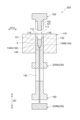
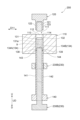
- the upper punch 120 has an upper pressing surface 124 for teeth that forms the teeth portion 10 of the core piece 7 between itself and the first lower punch 130, and an upper pressing surface 125 for a first flange portion and an upper pressing surface 126 for a second flange portion that form the first flange portion 20 and the second flange portion 30 of the core piece 7 between itself and the second lower punch 140
- the first lower punch 130 has a lower pressing surface 134 for teeth that forms the teeth portion 10 between itself and the upper punch 120
- the second lower punch 140 has a lower pressing surface 134 for teeth that forms the teeth portion 10 between itself and the upper punch 120
- the upper punch 120 has a first flange portion lower pressing surface 143 and a second flange portion lower pressing surface 144 which form the first flange portion 20 and the second flange portion 30, and the upper punch 120's teeth upper pressing surface 124 has a shape corresponding to the outer periphery 13 of the teeth portion 10, and the first lower punch 130'
- the first lower punch 130 and the second lower punch 140 are inserted into the forming hole 111 of the die 110, the soft magnetic powder 9 coated with an insulating material is supplied from above into the forming hole 111, the upper punch 120 is inserted into the forming hole 111, and the soft magnetic powder 9 is pressed by the upper punch 120 and the first lower punch 130 and the second lower punch 140, thereby making it possible to compact the above-mentioned core piece 7.
- This makes it possible to manufacture a core piece 7 that can increase the magnetic flux density.
- the core piece manufacturing method according to the first embodiment is a method for manufacturing the above-mentioned core piece 7 using the above-mentioned core piece manufacturing apparatus 100.
- the core piece manufacturing method includes a preparation process, a lower punch insertion process performed after the preparation process, a powder supply process performed after the lower punch insertion process, a pressing process performed after the powder supply process, and an extraction process performed after the pressing process.
- the above-mentioned core piece manufacturing device 100 and soft magnetic powder coated with an insulating material are prepared.
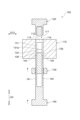
- FIGS. 18 and 19 are cross-sectional views showing the lower punch insertion process. As shown in FIG. 18 and FIG. 19, in the lower punch insertion process, the first lower punch 130 and the second lower punch 140 are inserted into the forming hole 111 of the die 110.
- the first mold portion 131 of the first lower punch 130 is inserted into the first punch space 115 of the forming hole 111, the second mold portion 132 of the first lower punch 130 is inserted into the second punch space 116 of the forming hole 111, and the teeth lower pressing portion 133 of the first lower punch 130 is inserted into the teeth space 112 of the forming hole 111. Then, the first mold portion 131 is disposed in the first punch space 115, the second mold portion 132 is disposed in the second punch space 116, and the teeth lower pressing surface 134 of the teeth lower pressing portion 133 is disposed in the teeth space 112.
- the bottom of the tooth space 112 is formed by the tooth lower pressing surface 134, the area near the tooth lower pressing surface 134 in the first punch space 115 is blocked by the first mold part 131, and the area near the tooth lower pressing surface 134 in the second punch space 116 is blocked by the second mold part 132.
- the first flange lower pressing portion 141 of the second lower punch 140 is inserted into the first flange space 113 of the forming hole 111, and the second flange lower pressing portion 142 of the second lower punch 140 is inserted into the second flange space 114 of the forming hole 111.
- the first flange lower pressing surface 143 of the second lower punch 140 is placed in the first flange space 113 of the forming hole 111, and the second flange lower pressing surface 144 of the second lower punch 140 is placed in the second flange space 114 of the forming hole 111.
- the first flange lower pressing surface 143 forms the bottom of the first flange space 113
- the second flange lower pressing surface 144 forms the bottom of the second flange space 114.
- the positions in the up-down direction UD of the first lower punch 130 and the second lower punch 140 are set so that the first flange lower pressing surface 143 and the second flange lower pressing surface 144 are at a lower position D than the tooth lower pressing surface 134.
- a space open to the upper U is formed in the forming hole 111 by the die 110, the first flange lower pressing surface 143 and the second flange lower pressing surface 144 of the second lower punch 140, and the inner surface 131a, inner surface 132a, tooth lower pressing surface 134, first flange inner pressing surface 138, and second flange inner pressing surface 139 of the first lower punch 130.
- FIGS. 20 and 21 are cross-sectional views showing the powder supplying process.
- soft magnetic powder 9 coated with an insulating material is supplied from the upper U to the forming hole 111.
- the soft magnetic powder 9 supplied to the forming hole 111 is supplied to a space open to the upper U, which is formed by the die 110, the first flange lower pressing surface 143 and the second flange lower pressing surface 144 of the second lower punch 140, and the inner surface 131a, inner surface 132a, teeth lower pressing surface 134, first flange inner pressing surface 138, and second flange inner pressing surface 139 of the first lower punch 130.
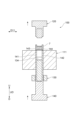
- Figures 22 and 23 are cross-sectional views showing the pressing process. As shown in Figures 20 to 23, in the pressing process, the upper punch 120 is inserted into the forming hole 111 of the die 110, and the soft magnetic powder 9 supplied to the forming hole 111 is pressed by the upper punch 120, the first lower punch 130, and the second lower punch 140 to form the core piece 7 formed by pressing the soft magnetic powder 9.
- the upper punch 120 is moved (lowered) downward D, and the upper pressing portion 121 for the teeth of the upper punch 120 is pressed into the space 112 for the teeth of the forming hole 111, the upper pressing portion 122 for the first flange portion of the upper punch 120 is pressed into the space 113 for the first flange portion of the forming hole 111, and the upper pressing portion 123 for the second flange portion of the upper punch 120 is pressed into the space 114 for the second flange portion of the forming hole 111.
- the first lower punch 130 is moved (raised) upward U, the first die portion 131 of the first lower punch 130 is further inserted into the first punch space 115 of the forming hole 111, the second die portion 132 of the first lower punch 130 is further inserted into the second punch space 116 of the forming hole 111, and the teeth lower pressing portion 133 of the first lower punch 130 is pressed into the teeth space 112 of the forming hole 111.
- the amount of movement of the second lower punch 140 upward U is made greater than the amount of movement of the first lower punch 130 upward U.
- the soft magnetic powder 9 supplied to the forming hole 111 is pressed by the upper punch 120, the first lower punch 130, and the second lower punch 140 to be molded into the core piece 7. That is, the soft magnetic powder 9 is pressed by the upper pressing surface 124 for teeth of the upper punch 120 and the lower pressing surface 134 for teeth of the first lower punch 130 to be molded into the teeth portion 10 of the core piece 7. In addition, the soft magnetic powder 9 is pressed by the upper pressing surface 125 for first flange of the upper punch 120 and the lower pressing surface 143 for first flange of the second lower punch 140 to be molded into the first flange portion 20 of the core piece 7.
- the soft magnetic powder 9 is pressed by the upper pressing surface 126 for the second flange of the upper punch 120 and the lower pressing surface 144 for the second flange of the second lower punch 140, thereby forming the second flange 30 of the core piece 7.
- the core piece 7 is formed by pressing the soft magnetic powder 9, that is, it is a compact of the soft magnetic powder 9.
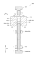
- Figures 24 and 25 are cross-sectional views showing the ejection process. As shown in Figures 22 to 25, in the ejection process, the core piece 7 is ejected from the molding hole 111.
- the upper punch 120 is moved (raised) upward U so that the upper punch 120 is ejected from the forming hole 111 and positioned above the die 110.
- the second lower punch 140 is also moved (raised) upward U so that the first flange lower pressing surface 143 and the second flange lower pressing surface 144 are flush with the upper surface of the die 110 or positioned above the die 110.
- the first flange 20 and the second flange 30 of the core piece 7 are pushed up by the first flange lower pressing portion 141 and the second flange lower pressing portion 142, and the core piece 7 is ejected from the first lower punch 130 and the forming hole 111.
- the core piece 7 is removed from the core piece manufacturing device 100, completing the manufacturing of the core piece 7.
- the first lower punch 130 and the second lower punch 140 are inserted into the forming hole 111, soft magnetic powder 9 coated with an insulating material is supplied from above into the forming hole 111, the upper punch 120 is inserted into the forming hole 111, and the soft magnetic powder 9 supplied into the forming hole 111 is pressed by the upper punch 120 and the first lower punch 130 and the second lower punch 140, thereby compacting the above-mentioned core piece 7. Then, after the core piece 7 has been compacted, it is possible to manufacture a core piece 7 that can increase the magnetic flux density by extracting the core piece from the forming hole 111.
- the upper punch 120 and the second lower punch 140 can be moved upward to easily remove the core piece 7 from the molding hole 111.
- the core piece manufacturing apparatus according to the second embodiment is basically the same as the core piece manufacturing apparatus according to the first embodiment, and differs from the core piece manufacturing apparatus according to the first embodiment only in that the first lower punch is divided into a first main lower punch and a first sub-lower punch. Therefore, only the differences from the core piece manufacturing apparatus according to the first embodiment will be described below, and the same matters as those in the core piece manufacturing apparatus according to the first embodiment will be omitted.
- Figure 26 is an exploded perspective view showing a core piece manufacturing apparatus according to the second embodiment.
- Figure 27 is a front view showing a core piece manufacturing apparatus according to the second embodiment.
- Figure 28 is a side view showing a core piece manufacturing apparatus according to the second embodiment.
- the core piece manufacturing apparatus 200 according to this embodiment comprises a die 110 having a forming hole 111, an upper punch 120 inserted into the forming hole 111 from above U, a first lower punch 230 inserted into the forming hole 111 from below D, and a second lower punch 140 inserted into the forming hole 111 from below D.
- the first lower punch 230 like the first lower punch 130 of the first embodiment (see Figures 15 to 17), has a first mold portion 131, a second mold portion 132, and a lower pressing portion for teeth 133.
- a lower pressing surface for teeth 134 is formed on the upper surface of the lower pressing portion for teeth 133.
- the lower pressing surface for teeth 134 has a bottom surface 135, a first side surface 136 (first side bottom surface 136a and portion 136b), and a second side surface 137 (second side bottom surface 137a and portion 137b).
- the first lower punch 230 has a first main lower punch 230A and a first auxiliary lower punch 230B that can move in the up-down direction UD relative to the first main lower punch 230A.
- the first main lower punch 230A has a first mold portion 131, a second mold portion 132, and a part of the lower pressing portion for teeth 133.
- the first main lower punch 230A has a slit extending in the vertical direction UD into which the first auxiliary lower punch 230B is inserted so as to be movable in the vertical direction UD.
- the slit of the first main lower punch 230A is formed in the lower pressing portion for teeth 133.
- the first main lower punch 230A has a part 134A of the lower pressing surface for teeth 134.
- the part 134A of the lower pressing surface for teeth 134 is composed of, for example, a part of the bottom surface 135, a first side surface 136 (first side bottom surface 136a and part 136b), and a second side surface 137 (second side bottom surface 137a and part 137b).
- the first auxiliary lower punch 230B has a remaining portion of the lower pressing portion for teeth 133.
- the first auxiliary lower punch 230B is inserted into a slit formed in the first main lower punch 230A so that it can move in the up and down direction UD relative to the first main lower punch 230A.
- the first auxiliary lower punch 230B has a remaining portion 134B of the lower pressing surface for teeth 134.
- the remaining portion 134B of the lower pressing surface for teeth 134 is constituted by, for example, a remaining portion of the bottom surface 135.
- the first lower punch 230 has a first main lower punch 230A having a portion 134A of the lower pressing surface for teeth 134, and a first auxiliary lower punch 230B having the remaining portion 134B of the lower pressing surface for teeth 134 and capable of moving in the vertical direction UD relative to the first main lower punch 230A. Therefore, after the core piece 7 has been powder-pressed, the first auxiliary lower punch 230B can be moved upward U relative to the first main lower punch 230A, thereby making it possible to easily extract the core piece 7 from the first main lower punch 230A.
- the first main lower punch 230A has the first side 136 (first side bottom surface 136a and portion 136b) and second side 137 (second side bottom surface 137a and portion 137b) of the lower pressing surface for teeth 134, and a portion of the bottom surface 135, and the first auxiliary lower punch 230B has the remaining portion of the bottom surface 135 of the lower pressing surface for teeth 134. Therefore, after the core piece 7 has been powder-compressed, the first auxiliary lower punch 230B can be moved upward U relative to the first main lower punch 230A, thereby making it possible to easily extract the core piece 7 from the first main lower punch 230A.
- the core piece manufacturing method according to the second embodiment is basically the same as the core piece manufacturing method according to the first embodiment, but differs from the core piece manufacturing method according to the first embodiment only in that the above-mentioned core piece 7 is manufactured using the above-mentioned core piece manufacturing device 200. Therefore, only the points that differ from the core piece manufacturing method according to the first embodiment will be described below, and the points that are the same as those in the core piece manufacturing method according to the first embodiment will be omitted.
- the core piece manufacturing method includes a preparation process, a lower punch insertion process performed after the preparation process, a powder supply process performed after the lower punch insertion process, a pressing process performed after the powder supply process, and an extraction process performed after the pressing process.
- the above-mentioned core piece manufacturing device 200 and soft magnetic powder coated with an insulating material are prepared.
- 29 and 30 are cross-sectional views showing the lower punch insertion process. As shown in Figs. 29 and 30, in the lower punch insertion process, the first lower punch 230 and the second lower punch 140 are inserted into the forming hole 111 of the die 110.
- a portion 134A of the lower pressing surface 134 for teeth of the first main lower punch 230A and the remaining portion 134B of the lower pressing surface 134 for teeth of the first auxiliary lower punch 230B are aligned, and the lower pressing surface 134 for teeth of the first lower punch 230 is formed by the first main lower punch 230A and the first auxiliary lower punch 230B.
- the first lower punch 230 (first main lower punch 230A and first auxiliary lower punch 230B) and the second lower punch 140 are inserted into the forming hole 111 of the die 110.
- the formation of the lower pressing surface 134 for teeth by the first main lower punch 230A and the first auxiliary lower punch 230B may be performed after the first main lower punch 230A and the first auxiliary lower punch 230B are inserted into the forming hole 111.
- Figures 31 and 32 are cross-sectional views showing the powder supplying process. As shown in Figures 29 to 32, in the powder supplying process, soft magnetic powder 9 coated with an insulating material is supplied from above U into the molding hole 111.
- Figures 33 and 34 are cross-sectional views showing the pressing process. As shown in Figures 31 to 34, in the pressing process, the upper punch 120 is inserted into the forming hole 111 of the die 110, and the soft magnetic powder supplied to the forming hole 111 is pressed by the upper punch 120, the first lower punch 230, and the second lower punch 140 to form the core piece 7 made of the pressed soft magnetic powder.
- Figures 35 and 36 are cross-sectional views showing the ejection process. As shown in Figures 33 to 36, in the ejection process, the core piece 7 is ejected from the molding hole 111.
- the upper punch 120 is moved (raised) upward U so that the upper punch 120 is ejected from the forming hole 111 and positioned above the die 110.
- the first auxiliary lower punch 230B is moved (raised) upward U relative to the first main lower punch 230A so that the remaining portion 134B of the teeth lower pressing surface 134 of the first auxiliary lower punch 230B is flush with the upper surface of the die 110 or positioned higher than the die 110.
- the first main lower punch 230A is not moved (raised) upward U, but the first main lower punch 230A may be moved (raised) upward U to the extent that the first auxiliary lower punch 230B can be moved (raised) upward U relative to the first main lower punch 230A.
- the teeth portion 10 of the core piece 7 is pushed up by the first auxiliary lower punch 230B, and the core piece 7 is extracted from the first main lower punch 230A and the forming hole 111.
- the second lower punch 140 may be moved (raised) upward U so that the first flange lower pressing surface 143 and the second flange lower pressing surface 144 are flush with the upper surface of the die 110 or positioned above the die 110.
- the core piece 7 is removed from the core piece manufacturing device 200, completing the manufacturing of the core piece 7.
- the upper punch 120 is moved upward and the first auxiliary lower punch 230B is moved upward U relative to the first main lower punch 230A, so that the core piece 7 can be easily extracted from the first main lower punch 230A and the core piece 7 can be easily extracted from the molding hole 111.
- the shape of the core piece may be changed as long as the first inner circumferential side end of the first side circumferential portion moves toward the second inner circumferential side end as it moves toward the inner circumferential portion.
- the second inner circumference side end of the teeth portion may not extend toward the first inner circumference side end as it approaches the inner circumference, but may extend in the first and second directions similar to the second outer circumference side end. Also, the inner and outer circumference portions of the teeth portion may not extend in the first and third directions.
- the first and second flanges do not have to be formed in a rectangular plate shape.
- the length of the first upper end face in the third direction is longer than the length of the first lower end face in the third direction, and the first front end face and the first rear end face may be formed so as to approach each other toward the first lower end.
- the length of the second upper end face in the third direction is longer than the length of the second lower end face in the third direction, and the second front end face and the second rear end face may be formed so as to approach each other toward the second lower end.
- the first and second flanges may have the same shape or different shapes.
- the present disclosure can be used as a core piece, a stator core, a stator, an axial gap motor, a core piece manufacturing device, and a core piece manufacturing method.
- first flange portion upper pressing portion 123... second flange portion upper pressing portion, 124... teeth upper pressing surface, 125... first flange portion upper pressing surface, 126... second flange portion upper pressing surface, 130... first lower punch, 131... first mold portion, 131a... inner surface, 132... second mold portion, 132a... inner surface, 133... teeth lower pressing portion, 134... teeth lower pressing surface, 135... bottom surface, 136... first side surface, 136a... first side bottom surface, 136b... portion, 137... second side surface, 137a... second side bottom surface, 137b...
Landscapes
- Engineering & Computer Science (AREA)
- Power Engineering (AREA)
- Manufacturing & Machinery (AREA)
- Iron Core Of Rotating Electric Machines (AREA)
Priority Applications (3)
| Application Number | Priority Date | Filing Date | Title |
|---|---|---|---|
| JP2025538174A JPWO2025027862A1 (https=) | 2023-08-03 | 2023-08-03 | |
| PCT/JP2023/028475 WO2025027862A1 (ja) | 2023-08-03 | 2023-08-03 | コア片、ステータコア、ステータ、アキシャルギャップモータ、コア片製造装置、及びコア片製造方法 |
| CN202380096287.XA CN121002753A (zh) | 2023-08-03 | 2023-08-03 | 铁芯片、定子铁芯、定子、轴向间隙马达、铁芯片制造装置及铁芯片制造方法 |
Applications Claiming Priority (1)
| Application Number | Priority Date | Filing Date | Title |
|---|---|---|---|
| PCT/JP2023/028475 WO2025027862A1 (ja) | 2023-08-03 | 2023-08-03 | コア片、ステータコア、ステータ、アキシャルギャップモータ、コア片製造装置、及びコア片製造方法 |
Publications (1)
| Publication Number | Publication Date |
|---|---|
| WO2025027862A1 true WO2025027862A1 (ja) | 2025-02-06 |
Family
ID=94394946
Family Applications (1)
| Application Number | Title | Priority Date | Filing Date |
|---|---|---|---|
| PCT/JP2023/028475 Pending WO2025027862A1 (ja) | 2023-08-03 | 2023-08-03 | コア片、ステータコア、ステータ、アキシャルギャップモータ、コア片製造装置、及びコア片製造方法 |
Country Status (3)
| Country | Link |
|---|---|
| JP (1) | JPWO2025027862A1 (https=) |
| CN (1) | CN121002753A (https=) |
| WO (1) | WO2025027862A1 (https=) |
Citations (1)
| Publication number | Priority date | Publication date | Assignee | Title |
|---|---|---|---|---|
| WO2021225050A1 (ja) * | 2020-05-08 | 2021-11-11 | 住友電気工業株式会社 | コア片、ステータコア、ステータ、回転電機、及びコア片の製造方法 |
-
2023
- 2023-08-03 WO PCT/JP2023/028475 patent/WO2025027862A1/ja active Pending
- 2023-08-03 JP JP2025538174A patent/JPWO2025027862A1/ja active Pending
- 2023-08-03 CN CN202380096287.XA patent/CN121002753A/zh active Pending
Patent Citations (1)
| Publication number | Priority date | Publication date | Assignee | Title |
|---|---|---|---|---|
| WO2021225050A1 (ja) * | 2020-05-08 | 2021-11-11 | 住友電気工業株式会社 | コア片、ステータコア、ステータ、回転電機、及びコア片の製造方法 |
Also Published As
| Publication number | Publication date |
|---|---|
| CN121002753A (zh) | 2025-11-21 |
| JPWO2025027862A1 (https=) | 2025-02-06 |
Similar Documents
| Publication | Publication Date | Title |
|---|---|---|
| KR20190005974A (ko) | 압분 자심, 스테이터 코어 및 스테이터 | |
| JP5583391B2 (ja) | 固定子積層鉄心 | |
| JP2010252560A (ja) | 回転電機用ランデル型鉄心の成形方法および一対のランデル型鉄心 | |
| WO2025027862A1 (ja) | コア片、ステータコア、ステータ、アキシャルギャップモータ、コア片製造装置、及びコア片製造方法 | |
| JP3888078B2 (ja) | コイル部品の製造方法およびその装置 | |
| JP2011109773A (ja) | 固定子鉄心及びその製造方法 | |
| JP5036064B2 (ja) | 偏肉形状部品の圧粉体成形方法および圧粉体成形金型装置 | |
| JP3425731B2 (ja) | セグメント形圧粉成形体成形方法及び装置 | |
| JP3693496B2 (ja) | 圧粉体の成形方法 | |
| KR100566513B1 (ko) | 파이프재의 홈부 성형 방법 | |
| JP5862927B2 (ja) | 湾曲板状部品の圧粉体成形金型装置 | |
| CN212147242U (zh) | 一种盘式电机及定子模具 | |
| WO2025238853A1 (ja) | コア片、ステータコア、ステータ、及びアキシャルギャップモータ | |
| JP2023050016A (ja) | 圧縮成形用金型、焼結磁石の製造方法、焼結磁石、ロータ、及びロータの製造方法 | |
| WO2025238852A1 (ja) | コア片、ステータコア、ステータ、及びアキシャルギャップモータ | |
| JP3788952B2 (ja) | 樹脂成形品の製造方法及びその装置 | |
| JPWO2025027862A5 (https=) | ||
| JPS59209042A (ja) | スキユ−を有する回転電機積層鉄心の製造方法 | |
| JPH0568938B2 (https=) | ||
| JP4465087B2 (ja) | 粉末成形体の製造方法 | |
| CN210911017U (zh) | 一种具有稳定离型结构的模仁 | |
| JPH0799756A (ja) | 電動機の固定子の製造方法 | |
| JP2011098392A (ja) | 切削工具の切刃部材の製造方法及び該製造方法に用いられる圧粉体のプレス成形金型 | |
| JP3612103B2 (ja) | マグネットホルダユニットおよびその生産方法 | |
| JP2008278685A (ja) | ステータおよびその製造方法 |
Legal Events
| Date | Code | Title | Description |
|---|---|---|---|
| 121 | Ep: the epo has been informed by wipo that ep was designated in this application |
Ref document number: 23947659 Country of ref document: EP Kind code of ref document: A1 |
|
| ENP | Entry into the national phase |
Ref document number: 2025538174 Country of ref document: JP Kind code of ref document: A |
|
| WWE | Wipo information: entry into national phase |
Ref document number: 2025538174 Country of ref document: JP |
|
| NENP | Non-entry into the national phase |
Ref country code: DE |