WO2025023020A1 - モータ制御装置及びモータ制御方法 - Google Patents
モータ制御装置及びモータ制御方法 Download PDFInfo
- Publication number
- WO2025023020A1 WO2025023020A1 PCT/JP2024/024902 JP2024024902W WO2025023020A1 WO 2025023020 A1 WO2025023020 A1 WO 2025023020A1 JP 2024024902 W JP2024024902 W JP 2024024902W WO 2025023020 A1 WO2025023020 A1 WO 2025023020A1
- Authority
- WO
- WIPO (PCT)
- Prior art keywords
- current
- phase
- motor control
- timing
- motor
- Prior art date
- Legal status (The legal status is an assumption and is not a legal conclusion. Google has not performed a legal analysis and makes no representation as to the accuracy of the status listed.)
- Pending
Links
Images



Classifications
-
- H—ELECTRICITY
- H02—GENERATION; CONVERSION OR DISTRIBUTION OF ELECTRIC POWER
- H02P—CONTROL OR REGULATION OF ELECTRIC MOTORS, ELECTRIC GENERATORS OR DYNAMO-ELECTRIC CONVERTERS; CONTROLLING TRANSFORMERS, REACTORS OR CHOKE COILS
- H02P21/00—Arrangements or methods for the control of electric machines by vector control, e.g. by control of field orientation
- H02P21/22—Current control, e.g. using a current control loop
-
- H—ELECTRICITY
- H02—GENERATION; CONVERSION OR DISTRIBUTION OF ELECTRIC POWER
- H02P—CONTROL OR REGULATION OF ELECTRIC MOTORS, ELECTRIC GENERATORS OR DYNAMO-ELECTRIC CONVERTERS; CONTROLLING TRANSFORMERS, REACTORS OR CHOKE COILS
- H02P27/00—Arrangements or methods for the control of AC motors characterised by the kind of supply voltage
- H02P27/04—Arrangements or methods for the control of AC motors characterised by the kind of supply voltage using variable-frequency supply voltage, e.g. inverter or converter supply voltage
- H02P27/06—Arrangements or methods for the control of AC motors characterised by the kind of supply voltage using variable-frequency supply voltage, e.g. inverter or converter supply voltage using DC to AC converters or inverters
- H02P27/08—Arrangements or methods for the control of AC motors characterised by the kind of supply voltage using variable-frequency supply voltage, e.g. inverter or converter supply voltage using DC to AC converters or inverters with pulse width modulation
Definitions
- the present invention relates to a motor control device and a motor control method.
- the motor control PWM inverter of Patent Document 1 has a current sensor on the DC bus of the inverter main circuit, and a phase current calculation unit that calculates the phase current based on the detection value of the current sensor and the PWM pulse output from a PWM pulse generation means, and the PWM pulse generation means outputs the PWM pulse with the timing interval between the rise or fall of the PWM pulse between each phase being equal to or greater than a predetermined value.
- phase current is detected at a constant current detection timing regardless of whether the motor is in regenerative or power running operation. Therefore, if the phase current is detected at a constant current detection timing regardless of whether the motor is in regenerative or power running operation, it may not be possible to detect the phase current that is desired to be detected (more specifically, the peak current).
- the desired phase current since it is not possible to detect the desired phase current, if the actual phase current becomes larger than the detected value of the phase current, an overcurrent state occurs in which a current exceeding the command current flows, which can cause the inverter circuit and/or motor to overheat.
- the present invention was made in consideration of the current situation, and its purpose is to provide a motor control device and a motor control method that can detect the desired phase current in both regenerative and power running operations when a three-phase brushless motor is driven by a 120-degree rectangular wave.
- the motor control device and motor control method according to the present invention switches the current detection timing within the current acquisition period depending on whether the three-phase brushless motor is in regenerative operation or power operation.
- the desired phase current can be detected in both regenerative and power running modes.
- FIG. 1 is a system diagram of an internal combustion engine for a vehicle.
- FIG. 1 is a diagram showing a control system for a three-phase brushless motor.
- 4 is a time chart showing a control operation of an inverter.
- FIG. 2 is a diagram showing the four quadrants of inverter control.
- 4 is a time chart showing changes in phase current during power running;
- 4 is a time chart showing changes in phase current during regenerative operation.
- 4 is a functional block diagram showing details of a current acquiring unit.
- FIG. 1 is a diagram showing an internal combustion engine for a vehicle equipped with a three-phase brushless motor to which a motor control device and a motor control method according to the present invention are applied.
- the internal combustion engine 101 is provided with an intake air flow rate sensor 103 in an intake duct 102 for detecting an intake air flow rate QA of the internal combustion engine 101 .
- the intake valve 105 opens and closes the intake port of the combustion chamber 104 of each cylinder.
- the fuel injection valve 106 injects fuel into the intake port 102a of each cylinder.
- the fuel injected by the fuel injection valve 106 is drawn into the combustion chamber 104 together with air through the intake valve 105, and is ignited and burned by spark ignition from the spark plug 107.
- the combustion pressure then pushes the piston 108 down toward the crankshaft 109, driving the crankshaft 109 to rotate.
- an exhaust valve 110 opens and closes the exhaust port of the combustion chamber 104 , and when the exhaust valve 110 opens, exhaust gas within the combustion chamber 104 is discharged to an exhaust pipe 111 .
- the exhaust pipe 111 is equipped with a catalytic converter 112 that incorporates a catalyst such as a three-way catalyst.
- the intake valve 105 opens and closes in accordance with the rotational position of an intake camshaft 115 a which is rotated by a crankshaft 109 . Further, the exhaust valve 110 opens and closes in accordance with the rotational position of an exhaust camshaft 115 b which is rotated by the crankshaft 109 .
- VVT mechanism 114 An electric variable valve timing mechanism 114 (hereinafter referred to as VVT mechanism 114) changes the rotational phase of the intake camshaft 115a relative to the crankshaft 109 by controlling the rotational speed of the three-phase brushless motor 12, thereby continuously changing the valve timing of the intake valve 105, which is an engine valve, in the advance and retard directions.
- VVT mechanism 114 includes a phase change mechanism that is disposed between a timing sprocket (not shown) and intake camshaft 115a and changes the relative rotational phase between the timing sprocket and intake camshaft 115a.
- the phase change mechanism includes a three-phase brushless motor 12 and a speed reduction mechanism that reduces the rotational speed of the three-phase brushless motor 12 and transmits the reduced rotational speed to the intake camshaft 115a.
- a reduced rotational force is transmitted to intake camshaft 115a, causing intake camshaft 115a to rotate forward or reverse relative to the timing sprocket, thereby changing the relative rotational phase between intake camshaft 115a and the timing sprocket.
- the ignition module 116 is directly attached to the spark plug 107 and supplies ignition energy to the spark plug 107 .
- the ignition module 116 includes an ignition coil and a power transistor that controls the energization of the ignition coil.
- the control system that controls the operation of the internal combustion engine 101 includes an engine control module 201 (hereinafter referred to as ECM 201) that controls fuel injection by the fuel injection valve 106 and ignition by the spark plug 107, and a VVT controller 202 that controls the VVT mechanism 114.
- ECM 201 engine control module
- VVT controller 202 corresponds to a motor control device that controls the three-phase brushless motor 12 of the VVT mechanism 114 .
- the ECM 201 and the VVT controller 202 are electronic control devices.
- the ECM 201 includes a microcomputer 201a
- the VVT controller 202 includes a microcomputer 202a.
- the microcomputers 201a and 202a each include a processor, a non-volatile memory, a volatile memory, and the like.
- the ECM 201 acquires signals output by various sensors and performs calculations according to programs stored in a non-volatile memory, thereby calculating and outputting the operation amounts of the fuel injection valve 106, the ignition module 116, and the like.
- the VVT controller 202 acquires signals sent by the ECM 201 and signals output by various sensors, and performs calculations according to programs stored in a non-volatile memory to calculate and output the operation amount of the VVT mechanism 114, specifically, the three-phase brushless motor 12.
- the internal combustion engine 101 is equipped with the intake air flow sensor 103 mentioned above, a crank angle sensor 203 that outputs a crank angle signal POS for each predetermined angular position of the crankshaft 109, an accelerator opening sensor 206 that detects the depression amount of the accelerator pedal 207, in other words, the accelerator opening ACC, a cam angle sensor 204 that outputs a cam angle signal CAM for each predetermined angular position of the intake camshaft 115a, a water temperature sensor 208 that detects the temperature TW of the cooling water of the internal combustion engine 101, and an air-fuel ratio sensor 209 that is installed in the exhaust pipe 111 upstream of the catalytic converter 112 and detects the air-fuel ratio AF based on the oxygen concentration in the exhaust.
- a crank angle sensor 203 that outputs a crank angle signal POS for each predetermined angular position of the crankshaft 109
- an accelerator opening sensor 206 that detects the depression amount of the accelerator pedal 207, in other words, the accelerator opening ACC
- the crank angle signal POS output by the crank angle sensor 203 is a pulse signal for each unit crank angle, and the signal output pattern is set so that one or a series of multiple pulses are missing for each crank angle corresponding to the stroke phase difference between the cylinders.
- the position where the pulse signal is missing in the crank angle signal POS is detected as a reference crank angle position.
- the cam angle signal CAM outputted by the cam angle sensor 204 is outputted for each crank angle corresponding to the stroke phase difference between the cylinders.
- the ECM 201 acquires signals output by these various sensors, and further acquires an on/off signal from an ignition switch 205 , which is a main switch for starting and stopping the internal combustion engine 101 .
- the three-phase brushless motor 12 of the VVT mechanism 114 is equipped with Hall sensors 12u, 12v, and 12w as motor rotational position sensors for detecting the positional relationship between the rotor and the three-phase coils, i.e., the U-phase coil, the V-phase coil, and the W-phase coil. Then, the VVT controller 202 acquires the motor rotational position signals output by the Hall sensors 12u, 12v, and 12w.
- the ECM 201 calculates a target rotational phase, which is a target value of the rotational phase of the intake camshaft 115a relative to the crankshaft 109, based on the engine operating conditions such as the engine load and engine speed obtained from the output signals of the various sensors described above, and also calculates an actual rotational phase based on the crank angle signal POS and the cam angle signal CAM. Then, the ECM 201 calculates a target rotational speed of the three-phase brushless motor 12 so that the actual rotational phase approaches the target rotational phase, and transmits a signal of the target rotational speed (in other words, a rotational speed command signal) to the VVT controller 202.
- a target rotational phase which is a target value of the rotational phase of the intake camshaft 115a relative to the crankshaft 109, based on the engine operating conditions such as the engine load and engine speed obtained from the output signals of the various sensors described above, and also calculates an actual rotational phase based on the crank angle signal POS and the cam angle
- the VVT controller 202 determines a target value of the motor current based on the actual rotational speed and the target rotational speed of the three-phase brushless motor 12, and controls the AC power supplied to the three-phase brushless motor 12 based on the actual motor current and the target value.
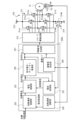
- FIG. 2 is a diagram showing a drive circuit 210 for the three-phase brushless motor 12 provided in the VVT controller 202 and a control function for the three-phase brushless motor 12 by a microcomputer 202 a of the VVT controller 202 .
- the microcomputer 202 a of the VVT controller 202 drives the three-phase brushless motor 12 with 120° rectangular wave drive that sequentially switches two phases to which a voltage is applied out of the three phases of the three-phase brushless motor 12 .
- the microcomputer 202a is a control unit that executes each step of a motor control method for driving the three-phase brushless motor 12 with a 120-degree rectangular wave.
- the 120-degree rectangular wave drive is also called 120-degree energization or simply rectangular wave drive.
- the three-phase brushless motor 12 has a cylindrical stator and a rotor equipped with a permanent magnet.
- the stator is provided with star-connected three-phase coils having phases U, V, and W.
- the rotor is rotatably provided in a space formed in the center of the stator.
- the Hall sensors 12u, 12v, and 12w are arranged around the rotor at 120 degree intervals.
- the microcomputer 202a determines the rotational position of the rotor from the sensor signals of the Hall sensors 12u, 12v, and 12w, and switches the selection pattern of the two phases to be energized every 60 electrical degrees according to the rotational position of the rotor.
- the drive circuit 210 of the three-phase brushless motor 12 includes an inverter 211 that supplies AC power to the three-phase brushless motor 12 , a DC power supply 212 for the inverter 211 , and an inverter drive circuit 213 .
- the inverter 211 is configured by connecting semiconductor switching elements 211a to 211f, such as FETs, in a three-phase bridge configuration.
- the gate terminals of the semiconductor switching elements 211 a - 211 f of the inverter 211 are connected to the output port of the inverter drive circuit 213 .
- the semiconductor switching elements 211a to 211f are switched on and off by gate control signals that the inverter drive circuit 213 outputs to the gate terminals of the semiconductor switching elements 211a to 211f.
- a shunt resistor 214A for detecting the motor current is disposed on the DC bus between the inverter 211 and the ground GND.
- a current sensor 214 that detects the motor current is configured by a shunt resistor 214A and an operational amplifier 214B that amplifies the voltage drop across the shunt resistor 214A.
- the shunt current signal output by the operational amplifier 214B that is, the detection signal of the phase current, is an analog signal of the potential difference [V] generated across the shunt resistor 214A.
- the microcomputer 202 a of the VVT controller 202 acquires the shunt current signal output by the current sensor 214 and the target rotation speed signal output by the ECM 201 , and outputs a PWM (Pulse Width Modulation) signal to the inverter drive circuit 213 .
- PWM Pulse Width Modulation
- the current acquisition unit 221 acquires a shunt current signal, which is an analog voltage signal, from the current sensor 214, and outputs the shunt current signal sampled at a predetermined current detection timing (in other words, current sampling timing) within the current acquisition period as a real phase current signal.
- a current acquisition period (in other words, a sampling period or a current detection period) during which the current acquisition unit 221 performs sampling processing of the shunt current signal will be described.
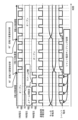
- FIG. 3 illustrates PWM control of the semiconductor switching elements 211a-211f in 120-degree rectangular wave driving.
- the microcomputer 202a employs lower-arm chopper control in which the semiconductor switching element of the upper arm of the inverter 211 is fixed on and the semiconductor switching element of the lower arm is PWM-controlled to be turned on and off.
- the microcomputer 202a fixes the semiconductor switching element 211c, which is the upper arm of the V phase, to on, and PWM-controls the on/off of the semiconductor switching element 211f, which is the lower arm of the W phase, based on a command voltage.
- the semiconductor switching element 211c is turned on, so that the terminal voltage of the V phase becomes the power supply potential
- the semiconductor switching element 211f is turned on, so that the terminal voltage of the W phase becomes the ground potential.
- a potential difference occurs between the V phase and the W phase, and a current flows from the V phase to the W phase.
- the microcomputer 202a samples the current flowing through the shunt resistor 214A during the on period of the semiconductor switching element of the lower arm, which is the timing when a phase current appears in the shunt resistor 214A, to detect the current value of the energized phase, i.e., the actual phase current.
- the on-period of the lower-arm semiconductor switching element becomes the current acquisition period.
- the microcomputer 202a can employ upper arm chopper control for PWM control of the semiconductor switching elements 211a-211f, in which the semiconductor switching elements of the lower arm are fixed on and the semiconductor switching elements of the upper arm are PWM-controlled to be turned on and off.
- the microcomputer 202a can perform complementary PWM (in other words, upper and lower complementary switching) in 120-degree rectangular wave driving.
- Complementary PWM is a switching control in which a semiconductor switching element in a lower arm and a semiconductor switching element in an upper arm are turned on and off in opposite phases.
- the signal of the actual phase current obtained by the current obtaining section 221 through sampling processing during the current obtaining period is obtained by the current control section 222 .
- the current control unit 222 sets a command voltage so as to bring the actual phase current closer to the target phase current.
- the rotation speed control unit 223 receives a signal of the target rotation speed and a signal of the actual rotation speed output by the ECM 201, and sets a target current so as to bring the actual rotation speed closer to the target rotation speed. Then, the rotation speed control unit 223 outputs a target current signal to the current control unit 222 .
- the rotation speed calculation unit 224 acquires the motor rotation position signals output by the Hall sensors 12u, 12v, and 12w, and determines the actual rotation speed of the three-phase brushless motor 12 based on the motor rotation position signals. Then, the rotation speed calculation unit 224 outputs a signal of the actual rotation speed of the three-phase brushless motor 12 to the rotation speed control unit 223 .
- the command voltage/duty converter 225 receives a command voltage signal from the current controller 222, and also receives a signal of the voltage of the DC power supply 212, that is, the power supply voltage. Then, the command voltage/duty conversion unit 225 calculates a command duty ratio for applying the command voltage to the three-phase brushless motor 12 from the command voltage and the power supply voltage.
- the current conduction phase determination unit 226 acquires the motor rotational position signals output by the Hall sensors 12u, 12v, and 12w, and by combining each motor rotational position signal, creates and outputs current conduction phase switching information (in other words, current conduction mode command information) every 60 degrees of rotation.
- the PWM signal generating unit 227 obtains a command duty ratio signal from the command voltage/duty conversion unit 225 , and obtains current conduction phase switching information from the current conduction phase determining unit 226 . Then, the PWM signal generating unit 227 generates PWM signals for each of the semiconductor switching elements 211a-211f of the inverter 211 based on the command duty ratio signal and the current-carrying phase switching information.
- the inverter drive circuit 213 acquires the PWM signal generated by the PWM signal generation unit 227, and generates and outputs gate signals (in other words, on/off control signals) for each of the semiconductor switching elements 211a-211f of the inverter 211 based on the PWM signal.
- the microcomputer 202a performs four-quadrant operation in which the powering (in other words, driving) and regenerative (in other words, braking) operations of the three-phase brushless motor 12 are performed in both forward and reverse rotation, thereby enabling highly responsive control of the valve timing.
- the current acquisition unit 221 has a function of switching the current detection timing within the current acquisition period between when the three-phase brushless motor 12 is in power running operation and when the three-phase brushless motor 12 is in regenerative operation.
- FIG. 4 shows the correlation between each operation mode of the four-quadrant operation and the motor rotation speed and motor current (in other words, motor torque).
- the first quadrant is a forward rotation and power running mode
- the second quadrant is a forward rotation and regenerative running mode
- the third quadrant is a reverse rotation and power running mode
- the fourth quadrant is a reverse rotation and regenerative running mode.
- powering operation is a mode in which current flows from DC power supply 212 to three-phase brushless motor 12
- regenerative operation is a mode in which power is returned from three-phase brushless motor 12 to DC power supply 212; if the power is positive, it is powering operation, and if the power is negative, it is regenerative operation. That is, the current obtaining unit 221 can determine whether the motor is in powering operation or regenerative operation based on the direction of the motor voltage and the direction of the motor current, and switch the current detection timing within the current obtaining period.
- the time chart of FIG. 5 illustrates an example of changes in the actual phase current, that is, the current flowing through the shunt resistor 214A, when the operation mode of the three-phase brushless motor 12 is the power operation.
- the actual phase current increases monotonically within the current acquisition period. Therefore, during powering operation, the current obtaining unit 221 can obtain the peak current, which is the peak value of the phase current, by setting the current detection timing based on the end timing of the current obtaining period.
- the time chart of FIG. 6 illustrates an example of a change in the actual phase current, that is, the current flowing through the shunt resistor 214A, when the operation mode of the three-phase brushless motor 12 is the regenerative operation.
- the operation mode of the three-phase brushless motor 12 is the regenerative operation
- the actual phase current monotonically decreases within the current acquisition period. Therefore, when the current acquisition unit 221 is in regenerative operation, if it sets the current detection timing based on the end timing of the current acquisition period, as is the case when the current acquisition unit 221 is in powering operation, it will not be able to acquire the peak current and will detect a phase current that is lower than the peak current.
- the current acquisition unit 221 when the current acquisition unit 221 acquires a current lower than the peak current during regenerative operation, and the inverter 211 is controlled to be driven based on this phase current, an overcurrent state occurs in which a current exceeding the command current flows, which may cause the inverter 211 and the three-phase brushless motor 12 to overheat. Therefore, the current acquisition unit 221 switches the current detection timing between power running operation and regenerative operation, thereby making it possible to acquire the peak current in both power running operation and regenerative operation, thereby preventing the inverter 211 and the three-phase brushless motor 12 from overheating.
- the current acquisition unit 221 acquires the peak current by sampling the shunt current signal based on the end timing of the current acquisition period. Furthermore, during regenerative operation in which the real phase current monotonically decreases during the current acquisition period, the current acquisition unit 221 acquires the peak current by sampling the shunt current signal based on the start timing of the current acquisition period. This allows the current obtaining unit 221 to obtain the peak current during both power running and regenerative operation, and makes it possible to prevent an overcurrent state in which a current exceeding the command current flows.
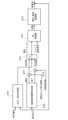
- FIG. 7 is a functional block diagram of the current obtaining unit 221.
- the powering/regeneration determination unit 221A acquires a command voltage signal from the current control unit 222, and further acquires an actual phase current signal that is a sampling result during a current acquisition period.
- the powering/regenerative determination unit 221A determines whether the operation is regenerative or powering based on the direction of the command voltage (in other words, the motor voltage) and the direction of the actual phase current (in other words, the motor current), and outputs a signal indicating whether the operation is regenerative or powering, i.e., an operation mode signal or a powering/regenerative determination signal.
- a signal indicating whether the operation is regenerative or powering i.e., an operation mode signal or a powering/regenerative determination signal.
- the powering/regenerative determination unit 221A can prevent the occurrence of hunting by determining whether the operation is powering or regenerative based on the target phase current instead of the actual phase current.
- the powering/regeneration determination unit 221A is configured to have hysteresis in the threshold value used for comparing with the actual phase current in the sign determination process, thereby causing the determination of switching the current detection timing to have hysteresis, thereby making it possible to prevent hunting from occurring.
- the powering/regenerative determination unit 221A can prevent hunting from occurring by determining a transition between powering operation and regenerative operation after a predetermined number of consecutive determinations of powering operation or regenerative operation.
- the current acquisition period determination unit 221B acquires a command duty ratio signal from the command voltage/duty conversion unit 225, and outputs signals indicating the start timing and end timing of the current acquisition period.
- the PWM control is lower-arm chopper control
- the ON period of the semiconductor switching element of the lower arm becomes the current acquisition period.
- the timing when the semiconductor switching element of the lower arm switches from off to on is the start timing of the current acquisition period, and the timing when the semiconductor switching element of the lower arm switches from on to off is the end timing of the current acquisition period.
- the adder 221C adds a predetermined time required for the rise of the shunt current signal to the start timing of the current acquisition period output by the current acquisition period determination unit 221B, and outputs the result as the current detection timing during regenerative operation.
- the current detection timing during regenerative operation is set based on the start timing of the current acquisition period, and is the point when a predetermined time (first set time) required for the shunt current signal to rise has elapsed from the start timing of the current acquisition period.
- the predetermined time required for the shunt current signal to rise is determined based on the allowable current detection error and the response speed (in other words, the time constant) of the shunt current signal.
- the subtraction unit 221D subtracts a predetermined time required for analog-to-digital conversion (AD conversion) of the shunt current signal from the end timing of the current acquisition period output by the current acquisition period determination unit 221B, and outputs the result as the current detection timing during powering operation.
- the current detection timing during powering operation is set based on the end timing of the current acquisition period, and is a point that precedes the end timing of the current acquisition period by a predetermined time (second set time) required for AD conversion of the shunt current signal.
- the current obtaining unit 221 sets the current detection timing during powering operation to be later than the current detection timing during regenerative operation.
- the real phase current decreases monotonically within the current acquisition period, so that the peak current can be detected by setting the current detection timing based on the start timing of the current acquisition period.
- the real phase current increases monotonically within the current acquisition period, so that the peak current can be detected by setting the current detection timing based on the end timing of the current acquisition period.
- the current detection timing switching unit 221E acquires the current detection timing during regenerative operation output by the addition unit 221C and the current detection timing during powering operation output by the subtraction unit 221D, and further acquires the judgment signal for powering operation and regenerative operation output by the powering/regenerative operation judgment unit 221A.
- the current detection timing switching unit 221E outputs the current detection timing in regenerative operation determined by the addition unit 221C.
- the current detection timing switching unit 221E outputs the current detection timing in powering operation determined by the subtraction unit 221D.
- the current detection timing switching unit 221E selects the current detection timing based on the start timing of the current acquisition period, and when the three-phase brushless motor 12 is in power operation, the current detection timing switching unit 221E selects the current detection timing based on the end timing of the current acquisition period. Therefore, when the three-phase brushless motor 12 is switched from regenerative operation to powering operation, the current detection timing is changed to a later timing within the current acquisition period, and conversely, when the three-phase brushless motor 12 is switched from powering operation to regenerative operation, the current detection timing is changed to an earlier timing within the current acquisition period.
- the AD converter 221F acquires the current detection timing output by the current detection timing switching unit 221E and the shunt current signal (analog voltage signal) output by the current sensor 214. Then, the AD converter 221F performs analog-to-digital conversion (AD conversion) on the shunt current signal, which is an analog voltage signal, at the current detection timing, and outputs the digital voltage signal obtained by the AD conversion. That is, the AD converter 221F samples the output of the current sensor 214 at the current detection timing.
- AD conversion analog-to-digital conversion
- the voltage-current converter 221G converts the digital voltage signal acquired from the AD converter 221F into a digital current signal, that is, a digital signal of the real-phase current, based on conversion characteristics according to the resistance value of the shunt resistor 214A and the gain of the operational amplifier 214B. Then, the voltage-current converter 221G outputs a digital signal of the actual phase current obtained by the conversion process to the current controller 222.
- the current obtaining unit 221 switches the current detection timing between the regenerative operation and the power running operation of the three-phase brushless motor 12, and samples the shunt current signal at the current detection timing.
- This allows the microcomputer 202a to detect the peak current, which is the phase current to be detected, in both regenerative operation and power running operation. Therefore, during regenerative operation, the microcomputer 202a obtains a phase current that is lower than the peak current and controls the inverter 211 to prevent an overcurrent state from occurring, which would cause the inverter 211 and the three-phase brushless motor 12 to overheat.
- the three-phase brushless motor 12 in the above embodiment is equipped with Hall sensors 12u, 12v, and 12w as rotational position sensors that detect the motor position, but the motor control device and motor control method of the present invention can also be applied to a sensorless three-phase brushless motor that does not have a rotational position sensor.
- the motor rotational position is detected by detecting the zero-cross point of the induced voltage appearing in the non-energized phase.
- the current sensor for detecting the phase currents is not limited to one sensor using a shunt resistor arranged on the DC bus of inverter 211, but may include a U-phase current sensor, a V-phase current sensor, and a W-phase current sensor that individually detect the current of each phase.
- the U-phase current sensor is arranged between the U-phase midpoint and the U-phase coil of inverter 211
- the V-phase current sensor is arranged between the V-phase midpoint and the V-phase coil of inverter 211
- the W-phase current sensor is arranged between the W-phase midpoint and the W-phase coil of inverter 211.
- the current acquisition unit 221 can select either the actual phase current sampled at a current detection timing based on the end timing of the current acquisition period, or the actual phase current sampled at a current detection timing based on the start timing of the current acquisition period, based on the result of distinguishing between regenerative operation and powering operation.
- the microcomputer 202a powering/regenerative determination unit 221A
- the microcomputer 202a can determine whether the operation is regenerative or powering, based on the motor rotation speed and motor torque.
- the three-phase brushless motor 12 is not limited to a motor used as an actuator for the VVT mechanism 114, and the motor control device and motor control method according to the present invention can be applied to a three-phase brushless motor that is operated in regenerative and power running mode by 120-degree rectangular wave drive.
Landscapes
- Engineering & Computer Science (AREA)
- Power Engineering (AREA)
- Control Of Motors That Do Not Use Commutators (AREA)
Priority Applications (1)
| Application Number | Priority Date | Filing Date | Title |
|---|---|---|---|
| JP2025535711A JPWO2025023020A1 (https=) | 2023-07-25 | 2024-07-10 |
Applications Claiming Priority (2)
| Application Number | Priority Date | Filing Date | Title |
|---|---|---|---|
| JP2023-120572 | 2023-07-25 | ||
| JP2023120572 | 2023-07-25 |
Publications (1)
| Publication Number | Publication Date |
|---|---|
| WO2025023020A1 true WO2025023020A1 (ja) | 2025-01-30 |
Family
ID=94374343
Family Applications (1)
| Application Number | Title | Priority Date | Filing Date |
|---|---|---|---|
| PCT/JP2024/024902 Pending WO2025023020A1 (ja) | 2023-07-25 | 2024-07-10 | モータ制御装置及びモータ制御方法 |
Country Status (2)
| Country | Link |
|---|---|
| JP (1) | JPWO2025023020A1 (https=) |
| WO (1) | WO2025023020A1 (https=) |
Citations (5)
| Publication number | Priority date | Publication date | Assignee | Title |
|---|---|---|---|---|
| JP2010124566A (ja) * | 2008-11-18 | 2010-06-03 | Toyota Motor Corp | 交流電動機の制御装置およびそれを搭載した電動車両 |
| JP2016092989A (ja) * | 2014-11-06 | 2016-05-23 | 日立オートモティブシステムズ株式会社 | モータ制御装置 |
| WO2019239628A1 (ja) * | 2018-06-11 | 2019-12-19 | 三菱電機株式会社 | コンバータ及びモータ制御装置 |
| WO2020217853A1 (ja) * | 2019-04-26 | 2020-10-29 | 工機ホールディングス株式会社 | 電気機器 |
| WO2022180896A1 (ja) * | 2021-02-24 | 2022-09-01 | 日立Astemo株式会社 | インバータ制御装置、電動車両システム |
-
2024
- 2024-07-10 JP JP2025535711A patent/JPWO2025023020A1/ja active Pending
- 2024-07-10 WO PCT/JP2024/024902 patent/WO2025023020A1/ja active Pending
Patent Citations (5)
| Publication number | Priority date | Publication date | Assignee | Title |
|---|---|---|---|---|
| JP2010124566A (ja) * | 2008-11-18 | 2010-06-03 | Toyota Motor Corp | 交流電動機の制御装置およびそれを搭載した電動車両 |
| JP2016092989A (ja) * | 2014-11-06 | 2016-05-23 | 日立オートモティブシステムズ株式会社 | モータ制御装置 |
| WO2019239628A1 (ja) * | 2018-06-11 | 2019-12-19 | 三菱電機株式会社 | コンバータ及びモータ制御装置 |
| WO2020217853A1 (ja) * | 2019-04-26 | 2020-10-29 | 工機ホールディングス株式会社 | 電気機器 |
| WO2022180896A1 (ja) * | 2021-02-24 | 2022-09-01 | 日立Astemo株式会社 | インバータ制御装置、電動車両システム |
Also Published As
| Publication number | Publication date |
|---|---|
| JPWO2025023020A1 (https=) | 2025-01-30 |
Similar Documents
| Publication | Publication Date | Title |
|---|---|---|
| JP6951538B2 (ja) | モータ駆動装置及びモータ駆動装置の制御方法 | |
| US10749453B1 (en) | Drive device and drive method of brushless motor | |
| JP5396101B2 (ja) | 可変動弁機構の制御装置 | |
| US5415139A (en) | Control system for controlling excess air ratio of internal combustion engine using a generator-motor | |
| JP2004147415A (ja) | 電動機の運転制御装置 | |
| JP4048785B2 (ja) | 電動機用制御装置 | |
| JP5356077B2 (ja) | 車両用モータの制御装置 | |
| WO2025023020A1 (ja) | モータ制御装置及びモータ制御方法 | |
| JP3688273B2 (ja) | 電動機の回転駆動制御装置 | |
| US20130249458A1 (en) | Universal control unit for brushed or brushless dc motor | |
| CN108377669B (zh) | 无刷电机的驱动装置及驱动方法 | |
| JP2008115752A (ja) | 電動過給機の制御装置 | |
| JP2010193539A (ja) | 3相モータの電流検出装置 | |
| JP2019024284A (ja) | 尿素噴射制御装置 | |
| JP2001145381A (ja) | モータの制御装置 | |
| US20260088746A1 (en) | Motor Control Apparatus and Motor Control Method | |
| JP2004229385A (ja) | 電動機の制御装置 | |
| JP7169218B2 (ja) | アクチュエータ制御装置 | |
| JP2010187425A (ja) | 自動車用ブラシレスモータの制御装置 | |
| JPH04251592A (ja) | 電動車両の車輪駆動用モータの制御装置 | |
| JP7545345B2 (ja) | ブラシレスモータの制御装置及び制御方法 | |
| JP7149398B2 (ja) | モータ駆動装置及びモータ駆動装置の制御方法 | |
| US12375014B2 (en) | Brushless motor control device and brushless motor control method | |
| JP2870205B2 (ja) | 排気ガス還流弁制御装置 | |
| CN110809668B (zh) | 发动机控制装置及发动机控制方法 |
Legal Events
| Date | Code | Title | Description |
|---|---|---|---|
| 121 | Ep: the epo has been informed by wipo that ep was designated in this application |
Ref document number: 24845401 Country of ref document: EP Kind code of ref document: A1 |
|
| ENP | Entry into the national phase |
Ref document number: 2025535711 Country of ref document: JP Kind code of ref document: A |
|
| WWE | Wipo information: entry into national phase |
Ref document number: 2025535711 Country of ref document: JP |
|
| NENP | Non-entry into the national phase |
Ref country code: DE |