WO2025022639A1 - 全固体電池 - Google Patents
全固体電池 Download PDFInfo
- Publication number
- WO2025022639A1 WO2025022639A1 PCT/JP2023/027553 JP2023027553W WO2025022639A1 WO 2025022639 A1 WO2025022639 A1 WO 2025022639A1 JP 2023027553 W JP2023027553 W JP 2023027553W WO 2025022639 A1 WO2025022639 A1 WO 2025022639A1
- Authority
- WO
- WIPO (PCT)
- Prior art keywords
- region
- solid
- electrode layer
- state battery
- positive electrode
- Prior art date
- Legal status (The legal status is an assumption and is not a legal conclusion. Google has not performed a legal analysis and makes no representation as to the accuracy of the status listed.)
- Pending
Links
Images


Classifications
-
- H—ELECTRICITY
- H01—ELECTRIC ELEMENTS
- H01M—PROCESSES OR MEANS, e.g. BATTERIES, FOR THE DIRECT CONVERSION OF CHEMICAL ENERGY INTO ELECTRICAL ENERGY
- H01M10/00—Secondary cells; Manufacture thereof
- H01M10/05—Accumulators with non-aqueous electrolyte
- H01M10/056—Accumulators with non-aqueous electrolyte characterised by the materials used as electrolytes, e.g. mixed inorganic/organic electrolytes
- H01M10/0561—Accumulators with non-aqueous electrolyte characterised by the materials used as electrolytes, e.g. mixed inorganic/organic electrolytes the electrolyte being constituted of inorganic materials only
- H01M10/0562—Solid materials
-
- H—ELECTRICITY
- H01—ELECTRIC ELEMENTS
- H01M—PROCESSES OR MEANS, e.g. BATTERIES, FOR THE DIRECT CONVERSION OF CHEMICAL ENERGY INTO ELECTRICAL ENERGY
- H01M10/00—Secondary cells; Manufacture thereof
- H01M10/05—Accumulators with non-aqueous electrolyte
- H01M10/058—Construction or manufacture
-
- Y—GENERAL TAGGING OF NEW TECHNOLOGICAL DEVELOPMENTS; GENERAL TAGGING OF CROSS-SECTIONAL TECHNOLOGIES SPANNING OVER SEVERAL SECTIONS OF THE IPC; TECHNICAL SUBJECTS COVERED BY FORMER USPC CROSS-REFERENCE ART COLLECTIONS [XRACs] AND DIGESTS
- Y02—TECHNOLOGIES OR APPLICATIONS FOR MITIGATION OR ADAPTATION AGAINST CLIMATE CHANGE
- Y02E—REDUCTION OF GREENHOUSE GAS [GHG] EMISSIONS, RELATED TO ENERGY GENERATION, TRANSMISSION OR DISTRIBUTION
- Y02E60/00—Enabling technologies; Technologies with a potential or indirect contribution to GHG emissions mitigation
- Y02E60/10—Energy storage using batteries
-
- Y—GENERAL TAGGING OF NEW TECHNOLOGICAL DEVELOPMENTS; GENERAL TAGGING OF CROSS-SECTIONAL TECHNOLOGIES SPANNING OVER SEVERAL SECTIONS OF THE IPC; TECHNICAL SUBJECTS COVERED BY FORMER USPC CROSS-REFERENCE ART COLLECTIONS [XRACs] AND DIGESTS
- Y02—TECHNOLOGIES OR APPLICATIONS FOR MITIGATION OR ADAPTATION AGAINST CLIMATE CHANGE
- Y02P—CLIMATE CHANGE MITIGATION TECHNOLOGIES IN THE PRODUCTION OR PROCESSING OF GOODS
- Y02P70/00—Climate change mitigation technologies in the production process for final industrial or consumer products
- Y02P70/50—Manufacturing or production processes characterised by the final manufactured product
Definitions
- the present invention relates to an all-solid-state battery.
- All-solid-state batteries that use solid electrolytes are known.
- those that have a configuration in which the solid electrolyte is supported by a porous body are known.
- By supporting the solid electrolyte in a porous body it is possible to give the electrolyte layer self-supporting properties and flexibility, making it easier to handle.
- Patent Document 1 JP 2016-031789 A discloses a solid electrolyte sheet that is a sheet containing a nonwoven fabric and a solid electrolyte on the surface and inside of the nonwoven fabric, where the weight of the nonwoven fabric is 8 g or less per square meter and the thickness of the nonwoven fabric is 10 ⁇ m or more and 25 ⁇ m or less.
- the electrolyte layer contains a porous material
- the presence of the porous material inhibits ion conduction. This can potentially weaken the output of the solid-state battery.
- the object of the present invention is therefore to provide a technology that can improve ionic conductivity in an all-solid-state battery having a structure in which a solid electrolyte is supported on a porous body.
- the all-solid-state battery according to the present invention comprises an electrolyte layer, and a positive electrode layer and a negative electrode layer arranged to sandwich the electrolyte layer in the stacking direction.
- the electrolyte layer comprises a first region including at least a solid electrolyte, and a second region arranged to surround the first region and including a solid electrolyte and a porous body. When viewed along the stacking direction, at least a portion of the first region overlaps with the positive electrode layer and the negative electrode layer.
- the density of the solid electrolyte in the first region is greater than the density of the solid electrolyte in the second region, and/or the density of the porous body in the first region is less than the density of the porous body in the second region.
- FIG. 1 is a schematic cross-sectional view showing an all-solid-state battery according to a first embodiment.
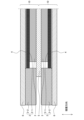
- FIG. 2 is an exploded perspective view showing the all-solid-state battery.
- FIG. 3 is a schematic cross-sectional view showing the all-solid-state battery 1 according to Modification Example 1-1.
- FIG. 4 is a plan view of the modified example 1-1.
- FIG. 5 is a schematic cross-sectional view showing an all-solid-state battery according to Modification 1-2.
- FIG. 6 is a schematic cross-sectional view showing an all-solid-state battery according to Modification 1-3.
- FIG. 7 is a schematic cross-sectional view showing an all-solid-state battery according to the third embodiment.
- FIG. 1 is a schematic cross-sectional view showing an all-solid-state battery according to a first embodiment.
- FIG. 2 is an exploded perspective view showing the all-solid-state battery.
- FIG. 3 is a schematic cross-sectional view showing the all-solid-state battery 1 according
- FIG. 8 is a schematic cross-sectional view showing an all-solid-state battery according to a fourth embodiment.
- FIG. 9 is a schematic cross-sectional view showing an all-solid-state battery according to the fifth embodiment.
- FIG. 10 is a plan view showing a portion of the all-solid-state battery according to the sixth embodiment.
- FIG. 11 is a plan view showing the modified example 6-1.
- FIG. 12 is a plan view showing the modified example 6-2.
- an “all-solid-state battery” is a secondary battery in which the electrolyte layer, the positive electrode layer, and the negative electrode layer are all substantially solid. Each layer may be “substantially” solid, and a small amount of liquid material may be used.
- FIG. 1 is a schematic cross-sectional view showing an all-solid-state battery 1 according to this embodiment.
- Fig. 2 is an exploded perspective view showing the all-solid-state battery 1.
- the all-solid-state battery 1 includes an electrolyte layer 2, a positive electrode layer 3, a negative electrode layer 4, a positive electrode current collector foil 5, and a negative electrode current collector foil 6.
- the electrolyte layer 2 is sandwiched between the positive electrode layer 3 and the negative electrode layer 4.
- the positive electrode current collector foil 5 and the negative electrode current collector foil 6 are disposed on the outer surfaces of the positive electrode layer 3 and the negative electrode layer 4, respectively. That is, in the all-solid-state battery 1, the positive electrode current collector foil 5, the positive electrode layer 3, the electrolyte layer 2, the negative electrode layer 4, and the negative electrode current collector foil 6 are stacked in this order along the stacking direction.
- a laminated structure consisting of an electrolyte layer 2, a positive electrode layer 3, a negative electrode layer 4, a positive electrode current collector foil 5, and a negative electrode current collector foil 6 is defined as one unit 10.
- a plurality of (two) units 10 are laminated.
- the all-solid-state battery 1 does not necessarily need to include a plurality of units 10.
- the unit 10 may be a single unit.
- the configuration shown in FIG. 2 corresponds to one unit 10.
- the positive electrode layer 3 is configured to absorb lithium during discharge and release lithium as lithium ions during charge.
- the positive electrode layer 3 is formed, for example, from a material containing a resin binder and a positive electrode active material dispersed in the resin binder.
- a lithium metal composite oxide can be used as the positive electrode active material.
- the thickness of the positive electrode layer 3 is, for example, 30 to 1000 ⁇ m, preferably 10 to 500 ⁇ m.
- the negative electrode layer 4 is configured to absorb lithium during charging and release lithium as lithium ions during discharging.
- the negative electrode layer 4 can be formed from a material containing a resin binder and a negative electrode active material dispersed in the resin binder.
- the negative electrode layer 4 may be realized by metallic lithium that precipitates between the electrolyte layer 2 and the negative electrode current collector foil 6 during charging. That is, the all-solid-state battery 1 may be a so-called precipitation-type secondary battery. In such a precipitation-type secondary battery, there may be almost no metallic lithium present as the negative electrode layer 4 in a fully discharged state. However, at least the metallic lithium that precipitates during charging functions as the negative electrode layer 4, and therefore is included in the all-solid-state battery 1 according to this embodiment.
- the electrolyte layer 2 is the part through which lithium ions are conducted during charging and discharging.
- the electrolyte layer 2 has electronic insulating properties and also functions as a separator that provides insulation between the positive electrode layer 3 and the negative electrode layer 4.
- the electrolyte layer 2 is a composite containing a solid electrolyte and a porous body.
- the solid electrolyte is filled into the pores of the porous body and is supported by the porous body.
- a nonwoven fabric for example, a nonwoven fabric can be used.
- the nonwoven fabric include polyester nonwoven fabric, polyethylene nonwoven fabric, and nonwoven fabric made of cellulose fibers.
- the thickness of the porous body is, for example, 5 to 100 ⁇ m, and preferably 7 to 20 ⁇ m.
- the specific material of the solid electrolyte is not particularly limited.
- a sulfide solid electrolyte can be used as the solid electrolyte.
- the sulfide solid electrolyte can be an LPS-based material (e.g., argyrodite (Li 6 PS 5 Cl)) or an LGPS-based material (e.g., Li 10 GeP 2 S 12 ).
- the configuration of the electrolyte layer 2 is devised.
- the configuration of the electrolyte layer 2 is described in detail below.
- the electrolyte layer 2 has a first region 2-1 and a second region 2-2.
- the first region 2-1 is surrounded by the second region 2-2.
- both the first region 2-1 and the second region 2-2 have a porous body and a solid electrolyte supported by the porous body. In each region, the pores of the porous body are filled with the solid electrolyte.
- the first region 2-1 is a region where ions are mainly conducted during charging and discharging. When viewed along the stacking direction, the first region 2-1 overlaps with the positive electrode layer 3 and the negative electrode layer 4 (hereinafter, these may be collectively referred to as the electrode layers).
- the second region 2-2 is a region that surrounds the first region 2-1.
- the outer peripheral edge of the second region 2-2 is located outside the outer peripheral edge of the electrode layer.
- the density of the solid electrolyte and/or the density of the porous body are different between the first region 2-1 and the second region 2-2. Specifically, at least one of the following conditions (A) and (B) is satisfied between the first region 2-1 and the second region 2-2.
- A) The density of the solid electrolyte in the first region 2-1 is greater than the density of the solid electrolyte in the second region 2-2.
- B) The density of the porous body in the first region 2-1 is smaller than the density of the porous body in the second region 2-2.
- the density of the porous body may be the same between the first region 2-1 and the second region 2-2, and the density of the solid electrolyte may be different.
- the density of the solid electrolyte may be the same between the first region 2-1 and the second region 2-2, and the density of the porous body may be different.
- the density of the solid electrolyte and the density of the porous body may both be different between the first region 2-1 and the second region 2-2.
- a high density solid electrolyte or a low density porous body may be referred to as “rich in solid electrolyte.”
- a high density porous body or a low density solid electrolyte may be referred to as “rich in porous body.”
- lithium ions are conducted mainly in the first region 2-1, which is the region that overlaps with the electrode layer.
- the first region 2-1 is rich in solid electrolyte, ion conduction is unlikely to be impeded by the porous body. In other words, even though the solid electrolyte is supported by the porous body, it is possible to suppress the decrease in ion conductivity caused by the porous body.
- the second region 2-2 is rich in porous material, so that the occurrence of cracks at the ends of the electrolyte layer 2 can be suppressed.
- the second region 2-2 since the second region 2-2 has insulating properties and its outer peripheral end is located outside the electrode layer, short circuits due to lithium precipitation that wraps around the ends are also prevented.
- the second region 2-2 is more flexible than the first region 2-1. Specifically, it is preferable that the elastic modulus of the second region 2-2 is smaller than that of the first region 2-1.
- the second region 2-2 has higher flexibility than the first region 2-1, it is possible to ensure uniform surface pressure.
- adjacent layers must be firmly bonded to obtain the desired charge/discharge characteristics. For this reason, the all-solid-state battery 1 is usually pressurized so as to be compressed along the stacking direction.
- the second region 2-2 has higher flexibility, the presence of the second region 2-2 makes it difficult to prevent pressure from being applied to the first region 2-1. Therefore, it becomes easier to apply pressure to the first region 2-1 with uniform surface pressure. This makes it easier to obtain the desired battery characteristics.
- a solid electrolyte is contained not only in the first region 2-1 but also in the second region 2-2. Therefore, the second region 2-2 also has a certain degree of function as an electrolyte layer (ion conduction function). For example, even if a part of the second region 2-2 unintentionally overlaps with the positive electrode layer 3 and the negative electrode layer 4 due to misalignment during manufacturing, the deterioration of the battery's performance can be minimized.
- the method for manufacturing the all-solid-state battery 1 in this embodiment is not particularly limited.
- a free-standing film to be used as the electrolyte layer 2 can be obtained by applying a slurry containing a solid electrolyte onto a porous body, allowing the slurry to penetrate into the porous body, and drying it.
- a second region 2-2 can be formed in addition to the first region 2-1.
- the obtained free-standing film can be used as the electrolyte layer 2 and laminated with the positive electrode layer 3, the negative electrode layer 4, the positive electrode current collector foil 5, and the negative electrode current collector foil 6 to obtain the all-solid-state battery 1.
- the outer peripheral end of the first region 2-1 when viewed along the stacking direction, the outer peripheral end of the first region 2-1 is located inside the outer peripheral ends of the positive electrode layer 3 and the negative electrode layer 4.
- the outer peripheral end of the positive electrode layer 3 is aligned with the outer peripheral end of the negative electrode layer 4.
- This configuration is preferable because it makes the end of the first region 2-1 less likely to crack. If the outer peripheral end of the first region 2-1 is located outside the positive electrode layer 3 and the negative electrode layer 4, the end of the first region 2-1 will not be supported in the stacking direction and will be more likely to crack. In contrast, if the outer peripheral end of the first region 2-1 is located inside each electrode layer, the end of the first region 2-1 will be less likely to crack, and reliability will be improved.
- the positional relationship between the first region 2-1, the positive electrode layer 3, and the outer periphery of the negative electrode layer 4 can be changed as appropriate depending on the application, etc. Below, the positional relationship between the outer periphery is explained with reference to modified examples.
- FIG. 3 is a schematic cross-sectional view showing an all-solid-state battery 1 according to Modification 1-1.
- Fig. 4 is a plan view of this modification, showing the positions of the outer peripheral ends of the electrolyte layer 2, the positive electrode layer 3, and the negative electrode layer 4.
- the outer peripheral end of the negative electrode layer 4 when viewed along the stacking direction, is located outside the outer peripheral end of the positive electrode layer 3.
- the outer peripheral end of the first region 2-1 is located inside the outer peripheral end of the positive electrode layer 3.
- the other points are the same as the configuration shown in Fig. 1.
- the outer peripheral edge of the negative electrode layer 4 may be positioned outside the outer peripheral edge of the positive electrode layer 3 in order to prevent excessive precipitation of lithium at the ends. Even in such a case, if the outer peripheral edge of the first region 2-1 is positioned inside the outer peripheral edge of the positive electrode layer 3, the end of the first region 2-1 is less likely to crack, and reliability can be improved.
- (Variation 1-2) 5 is a schematic cross-sectional view showing an all-solid-state battery 1 according to Modification 1-2.
- the outer peripheral edge of the first region 2-1 coincides with the outer peripheral edge of the positive electrode layer 3.
- the outer peripheral edge of the negative electrode layer 4 is located outside the outer peripheral edge of the positive electrode layer 3.
- this modification has the end of the first region 2-1 located on the outside, making it more susceptible to cracking.
- the area of the first region 2-1 is larger. Therefore, the ionic conductivity between the positive electrode layer 3 and the negative electrode layer 4 can be further increased.
- (Variation 1-3) 6 is a schematic cross-sectional view showing an all-solid-state battery 1 according to Modification 1-3.
- the outer peripheral end of the first region 2-1 when viewed along the stacking direction, the outer peripheral end of the first region 2-1 is located outside the outer peripheral end of the positive electrode layer 3.
- the outer peripheral end of the first region 2-1 coincides with the outer peripheral end of the negative electrode layer 4, or is located inside the outer peripheral end of the negative electrode layer 4.
- FIG. 6 shows, as a specific example, a case where the outer peripheral end of the first region 2-1 coincides with the outer peripheral end of the negative electrode layer 4.
- the other configurations are the same as those of Modification 1-2.
- the outer peripheral edge of the first region 2-1 is located further outward than in modification 1-2. Therefore, the edge of the first region 2-1 is more likely to crack than in modification 1-2. However, because the area of the first region 2-1 is larger, the ionic conductivity between the positive electrode layer 3 and the negative electrode layer 4 can be further increased compared to modification 1-2.
- the porous body is frame-shaped.
- the solid electrolyte is present in both the first region 2-1 and the second region 2-2. The solid electrolyte in the first region 2-1 is supported by the porous body in the second region 2-2.
- the density of the porous body in the first region 2-1 can be said to be zero. Therefore, condition (B) (see below) described in the first embodiment is necessarily satisfied. (B) The density of the porous body in the first region 2-1 is smaller than the density of the porous body in the second region 2-2.
- the density of the solid electrolyte in the first region 2-1 and the density of the solid electrolyte in the second region 2-2 may be the same or different.
- the ionic conductivity does not decrease during charging and discharging. In other words, this is more preferable from the viewpoint of ionic conductivity.
- the method for producing the electrolyte layer 2 in this embodiment is not particularly limited. For example, first, a frame-shaped porous body is prepared. Then, a slurry containing a solid electrolyte is supplied onto the porous body. Then, the slurry is filled into the pores of the porous body and into the frame using an applicator or the like. Thereafter, a drying process is carried out as necessary. In this way, a free-standing film to be used as the electrolyte layer 2 can be obtained.
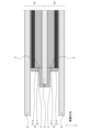
- FIG. 7 is a schematic cross-sectional view showing an all-solid-state battery 1 according to this embodiment.
- the second region 2-2 is thicker than the first region 2-1.
- the outer peripheral edges of the positive electrode collector foil 5 and the negative electrode collector foil 6 are located outside the outer peripheral edges of the electrode layers (positive electrode layer 3 and negative electrode layer 4).
- the second region 2-2 has a thickness that allows it to contact the positive electrode collector foil 5 and the negative electrode collector foil 6 in the stacking direction.
- the second region 2-2 is thick, so it is possible to fill gaps in the stacking direction. That is, the outer peripheral edge of the second region 2-2 is located outside the outer peripheral edge of the electrode layer. If the thickness of the second region 2-2 were less than the thickness of the first region 2-1, spaces would be created on both sides of the second region in the stacking direction. As a result, the second region 2-2 would be easily damaged by vibration, etc.
- the second region 2-2 is thick, so it is possible to eliminate the spaces that are created on both sides in the stacking direction. That is, the second region 2-2 is fixed from both sides in the stacking direction. This makes it possible to more reliably prevent damage to the second region 2-2 due to vibration, etc.
- FIG. 8 is a schematic cross-sectional view showing an all-solid-state battery 1 according to this embodiment.
- the electrolyte layer 2 is bent between the first region 2-1 and the second region 2-2.
- the second region 2-2 is joined to the side surface of the positive electrode layer 3.
- the second region 2-2 is also joined to the surface of the positive electrode current collector foil 5.
- the outer peripheral edge of the positive electrode current collector foil 5 is located outside the outer peripheral edge of the positive electrode layer 3.
- the second region 2-2 is bent so as to follow the side surface of the positive electrode layer 3 and the surface of the positive electrode current collector foil 5.
- the second region 2-2 is fixed to the positive electrode layer 3 and the positive electrode current collecting foil 5. This makes it possible to more reliably prevent damage to the second region 2-2 due to vibrations and the like. As a result, the insulation at the end of the electrolyte layer 2 can be improved, and reliability can be further improved.
- the second region 2-2 is bonded to both the positive electrode layer 3 and the positive electrode current collector foil 5. However, it is sufficient that the second region 2-2 is bonded to either the positive electrode layer 3 or the positive electrode current collector foil 5.
- the second region 2-2 may also be fixed to the negative electrode side, rather than to the positive electrode side. In other words, the second region 2-2 may be bonded to at least one of the negative electrode layer 4 and the negative electrode current collector foil 6. Even when these configurations are adopted, the second region 2-2 is fixed, so damage due to vibration, etc. can be prevented.
- FIG. 9 is a schematic cross-sectional view showing the all-solid-state battery 1 according to this embodiment.
- the second region 2-2 also covers the end face of the positive electrode current collector foil 5.
- the second region 2-2 may be joined to the negative electrode side instead of the positive electrode side.
- the second region 2-2 may be arranged so as to cover the end face of the negative electrode current collector foil 6.
- FIG. 10 is a plan view showing a portion of the all-solid-state battery 1 according to this embodiment.
- FIG. 10 shows the layout of the first region 2-1, the second region 2-2, the positive electrode layer 3, and the negative electrode layer 4.
- the first region 2-1 is divided into multiple regions. That is, the first region 2-1 has multiple first region elements (2-2-1, 2-1-2). When viewed along the stacking direction, each of the first region elements (2-2-1, 2-1-2) overlaps with an electrode layer (positive electrode layer 3 and negative electrode layer 4).
- FIG. 11 is a plan view showing modified example 6-1.
- the first region 2-1 has a plurality of first region elements (2-1-1 to 2-1-5). Some of the plurality of first region elements (2-1-1 to 2-1-5) protrude outside the electrode layer (positive electrode layer 3 and negative electrode layer 4) in some regions. However, any of the plurality of first region elements (2-1-1 to 2-1-5) overlaps the electrode layer (positive electrode layer 3 and negative electrode layer 4) at least in part.
- (Variation 6-2) 12 is a plan view showing a modified example 6-2.
- the first region 2-1 is divided into four first region elements (2-1-1 to 2-1-4). Even when such a configuration is adopted, it is possible to prevent a decrease in ionic conductivity in each of the first region elements (2-2-1 to 2-1-4), and a certain effect is achieved.
- An all-solid-state battery comprising: an electrolyte layer 2 including a porous body and a solid electrolyte supported by the porous body; and a cathode layer 3 and an anode layer 4 arranged to sandwich the electrolyte layer 2 in a stacking direction, wherein the electrolyte layer 2 comprises a first region 2-1 including at least a solid electrolyte, and a second region 2-2 arranged to surround the first region 2-1 and including a solid electrolyte and a porous body, wherein at least a portion of the first region 2-1 overlaps with the cathode layer 3 and the anode layer 4 when viewed along the stacking direction, and a density of the solid electrolyte in the first region 2-1 is greater than a density of the solid electrolyte in the second region 2-2 and/or a density of the porous body in the first region 2-1 is less than a density of the porous body in the second region 2-2.
- the solid electrolyte is densely present in the first region 2-1, or the porous body is sparse, so that the solid electrolyte is supported by the porous body while still suppressing a decrease in ionic conductivity.
- This configuration makes it less likely that cracks will occur at the ends of the first region 2-1.
- the area of the first region 2-1 is large, which can further improve ionic conductivity.
- the area of the first region 2-1 is larger, which can further improve ionic conductivity.
- This configuration makes it more difficult for cracks to occur in the second region 2-2, improving reliability.
- This configuration makes it possible to eliminate the spaces that occur on both sides of the second region 2-2 in the stacking direction, and to fix the second region 2-2 in place. As a result, damage to the second region 2-2 due to the effects of vibrations and the like can be more reliably prevented.
- Appendix 8 The all-solid-state battery according to any one of appendices 1 to 7, further comprising a positive electrode current collector foil 5 disposed on the positive electrode layer 3, and a negative electrode current collector foil 6 disposed on the negative electrode layer 4, wherein the second region 2-2 is in contact with a side surface of the positive electrode layer 3 or the positive electrode current collector foil 5, and/or is in contact with a side surface of the negative electrode layer 4 or the negative electrode current collector foil 6.
- This configuration allows the second region 2-2 to be fixed, and damage to the second region 2-2 due to the effects of vibrations and the like can be more reliably prevented.
- This configuration makes it possible to more reliably prevent short circuits between the positive and negative electrodes.
- the ionic conductivity can be improved in the areas where each first region element overlaps with the electrode layer, so a certain degree of effect can be achieved.
Landscapes
- Chemical & Material Sciences (AREA)
- Engineering & Computer Science (AREA)
- Manufacturing & Machinery (AREA)
- Chemical Kinetics & Catalysis (AREA)
- Electrochemistry (AREA)
- General Chemical & Material Sciences (AREA)
- Physics & Mathematics (AREA)
- Condensed Matter Physics & Semiconductors (AREA)
- General Physics & Mathematics (AREA)
- Inorganic Chemistry (AREA)
- Secondary Cells (AREA)
Priority Applications (3)
| Application Number | Priority Date | Filing Date | Title |
|---|---|---|---|
| PCT/JP2023/027553 WO2025022639A1 (ja) | 2023-07-27 | 2023-07-27 | 全固体電池 |
| JP2025535523A JPWO2025022639A1 (https=) | 2023-07-27 | 2023-07-27 | |
| CN202380100781.9A CN121569382A (zh) | 2023-07-27 | 2023-07-27 | 全固态电池 |
Applications Claiming Priority (1)
| Application Number | Priority Date | Filing Date | Title |
|---|---|---|---|
| PCT/JP2023/027553 WO2025022639A1 (ja) | 2023-07-27 | 2023-07-27 | 全固体電池 |
Publications (1)
| Publication Number | Publication Date |
|---|---|
| WO2025022639A1 true WO2025022639A1 (ja) | 2025-01-30 |
Family
ID=94374570
Family Applications (1)
| Application Number | Title | Priority Date | Filing Date |
|---|---|---|---|
| PCT/JP2023/027553 Pending WO2025022639A1 (ja) | 2023-07-27 | 2023-07-27 | 全固体電池 |
Country Status (3)
| Country | Link |
|---|---|
| JP (1) | JPWO2025022639A1 (https=) |
| CN (1) | CN121569382A (https=) |
| WO (1) | WO2025022639A1 (https=) |
Citations (2)
| Publication number | Priority date | Publication date | Assignee | Title |
|---|---|---|---|---|
| JP2020173953A (ja) * | 2019-04-10 | 2020-10-22 | 本田技研工業株式会社 | 固体電解質シート、全固体電池、セパレータ及びリチウムイオン電池 |
| WO2022195926A1 (ja) * | 2021-03-16 | 2022-09-22 | ビークルエナジージャパン株式会社 | 固体電解質シート、及びこれを使用した固体電解質二次電池 |
-
2023
- 2023-07-27 WO PCT/JP2023/027553 patent/WO2025022639A1/ja active Pending
- 2023-07-27 JP JP2025535523A patent/JPWO2025022639A1/ja active Pending
- 2023-07-27 CN CN202380100781.9A patent/CN121569382A/zh active Pending
Patent Citations (2)
| Publication number | Priority date | Publication date | Assignee | Title |
|---|---|---|---|---|
| JP2020173953A (ja) * | 2019-04-10 | 2020-10-22 | 本田技研工業株式会社 | 固体電解質シート、全固体電池、セパレータ及びリチウムイオン電池 |
| WO2022195926A1 (ja) * | 2021-03-16 | 2022-09-22 | ビークルエナジージャパン株式会社 | 固体電解質シート、及びこれを使用した固体電解質二次電池 |
Also Published As
| Publication number | Publication date |
|---|---|
| CN121569382A (zh) | 2026-02-24 |
| JPWO2025022639A1 (https=) | 2025-01-30 |
Similar Documents
| Publication | Publication Date | Title |
|---|---|---|
| US10439187B2 (en) | Laminar battery system | |
| JP5779828B2 (ja) | 段差を有する電極組立体、それを含む電池セル、電池パック及びデバイス | |
| JP7160922B2 (ja) | 固体電池用正極、固体電池用正極の製造方法、および固体電池 | |
| JP7488984B2 (ja) | 蓄電モジュール | |
| JP2006012835A (ja) | 二次電池 | |
| KR20230085080A (ko) | 이차 전지 | |
| CN101167203B (zh) | 电池 | |
| JPH10270068A (ja) | 角型電池およびその製造方法 | |
| US20260074398A1 (en) | Electric power storage module | |
| JP2023039756A (ja) | 全固体電池 | |
| JP2022016904A (ja) | 蓄電モジュール | |
| JP7810095B2 (ja) | 蓄電モジュール | |
| WO2025022639A1 (ja) | 全固体電池 | |
| JP7459758B2 (ja) | 蓄電セル | |
| JP2023149424A (ja) | 全固体電池 | |
| JP2024088116A (ja) | 蓄電モジュール製造方法、及び、蓄電モジュール | |
| JP2023107541A (ja) | 全固体電池 | |
| WO2025022640A1 (ja) | 全固体電池用電解質複合体及び全固体電池 | |
| WO2025046659A1 (ja) | 全固体電池 | |
| JP2025067216A (ja) | 全固体電池 | |
| JP2025085458A (ja) | 全固体電池 | |
| JP7847946B2 (ja) | 電池及び電池の製造方法 | |
| JP2025090235A (ja) | 二次電池 | |
| JP7852478B2 (ja) | 蓄電装置 | |
| US20250309331A1 (en) | Method of manufacturing all-solid-state battery |
Legal Events
| Date | Code | Title | Description |
|---|---|---|---|
| 121 | Ep: the epo has been informed by wipo that ep was designated in this application |
Ref document number: 23946720 Country of ref document: EP Kind code of ref document: A1 |
|
| ENP | Entry into the national phase |
Ref document number: 2025535523 Country of ref document: JP Kind code of ref document: A |
|
| WWE | Wipo information: entry into national phase |
Ref document number: 2025535523 Country of ref document: JP |
|
| NENP | Non-entry into the national phase |
Ref country code: DE |