WO2025022576A1 - 工作機械 - Google Patents
工作機械 Download PDFInfo
- Publication number
- WO2025022576A1 WO2025022576A1 PCT/JP2023/027224 JP2023027224W WO2025022576A1 WO 2025022576 A1 WO2025022576 A1 WO 2025022576A1 JP 2023027224 W JP2023027224 W JP 2023027224W WO 2025022576 A1 WO2025022576 A1 WO 2025022576A1
- Authority
- WO
- WIPO (PCT)
- Prior art keywords
- workpiece
- spindle
- turret
- center
- chuck
- Prior art date
- Legal status (The legal status is an assumption and is not a legal conclusion. Google has not performed a legal analysis and makes no representation as to the accuracy of the status listed.)
- Pending
Links
Images




Classifications
-
- B—PERFORMING OPERATIONS; TRANSPORTING
- B23—MACHINE TOOLS; METAL-WORKING NOT OTHERWISE PROVIDED FOR
- B23B—TURNING; BORING
- B23B23/00—Tailstocks; Centres
-
- B—PERFORMING OPERATIONS; TRANSPORTING
- B23—MACHINE TOOLS; METAL-WORKING NOT OTHERWISE PROVIDED FOR
- B23B—TURNING; BORING
- B23B3/00—General-purpose turning-machines or devices, e.g. centre lathes with feed rod and lead screw; Sets of turning-machines
- B23B3/30—Turning-machines with two or more working-spindles, e.g. in fixed arrangement
Definitions
- the present invention relates to a machine tool equipped with a core stock for a work spindle device.
- a core stock is provided opposite the spindle unit that grips the shaft workpiece to stabilize the rotation.
- a machine tool having such a core stock is also disclosed in Patent Document 1 listed below.
- a first core stock and a second core stock are provided back-to-back between the first spindle unit and the second spindle unit. Both the first core stock and the second core stock are movably attached to their respective guide rails, allowing the operator to adjust the distance between the first spindle unit or the second spindle unit.
- first and second spindle units are provided with first and second turret units, and a number of turret tools are attached at equal intervals to each turret tool rest.
- a specific turret tool is then indexed according to the machining content, and machining of the workpiece is performed.
- both ends are supported by the spindle chuck and first core stock of the first spindle unit.
- a machine tool having a similar core stock is disclosed in the following Patent Document 2.
- both center jigs equivalent to the core stock are provided on a third turret mounted at one location in the tool station.
- the machine tool of the first conventional example is configured so that the first and second core stocks simply move on guide rails, it is conceivable that the first or second turret device will interfere with the first and second core stocks when machining a workpiece other than a shaft workpiece. To avoid this interference, it is necessary to widen the range of movement of the first and second core stocks, which would result in an increase in the size of the machine tool. There are also restrictions such as the need to reduce the dimensions of the turret tool rest.
- the present invention aims to solve this problem by providing a machine tool equipped with a core stock for a work spindle device.
- the machine tool comprises a work spindle device that imparts rotation to a work held by a spindle chuck, a turret device in which a turret tool rest on which tools used to machine the work held by the spindle chuck are attached is configured to move in a direction parallel to or perpendicular to the axis of the work spindle, and a core support table equipped with a retraction mechanism that displaces a rotatable center rod that abuts against the center of rotation of the work from a direction facing the spindle chuck to a position away from the center of rotation.
- the machine tool includes a first work spindle device that is fixed to a bed and rotates a workpiece held by a first spindle chuck, a second work spindle device that is assembled so as to be movable in a direction parallel to the spindle relative to the bed and rotates a workpiece held by a second spindle chuck that is coaxial with the first spindle chuck, a turret device that is assembled so as to be movable in a direction parallel to the spindle relative to the bed and in which a turret tool rest to which tools used for machining the workpieces held by the first spindle chuck and the second spindle chuck are attached is configured to move in a direction parallel to or perpendicular to the spindles of the first work spindle device and the second work spindle device, and a core support table that has centers on both ends and is equipped with a retraction mechanism that displaces a rotatable center rod that abuts
- the center rod of the core push table is displaced by the retraction mechanism to a position away from the center of rotation of the spindle (corresponding to the center of rotation of the workpiece being machined), preventing interference between each device and the core push table.
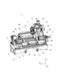
- FIG. 1 is a perspective view showing one embodiment of a machine tool, in particular the internal structure of the machine body.
- FIG. FIG. 1 is a perspective view showing an internal structure of one embodiment of a machine tool, in which a cover member for a coolant is added to a portion of the internal structure.
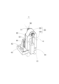
- FIG. 2 is a perspective view showing a tailstock that tail-supports the workpiece of the first workpiece spindle device.
- FIG. FIG. 2 is a cross-sectional view showing the configuration of the center part of the core stock.
- FIG. 13 is a diagram showing the state of the core stock during the first processing.
- FIG. 13 is a diagram showing the state of the tailstock when the workpiece is transferred between the first and second workpiece spindle devices.
- FIG. 13 is a diagram showing the state of the core stock during the second processing.
- FIG. 1 is a diagram showing the machine tool of this embodiment, and in particular is a perspective view showing the internal structure of the machine body.
- the machine tool 1 of this embodiment is a small NC lathe in which various processing devices for processing a workpiece are mounted on a slant-type bed 6.
- the top surface of the bed 6 is inclined forward, and mounted thereon are a first workpiece spindle device 3 that rotatably grips the workpiece, a second workpiece spindle device 4 that is disposed opposite the first workpiece spindle device 3 and rotatably grips the workpiece, and a turret device 5 having multiple turret tools T.
- the first work spindle device 3 is arranged on the left side, and the second work spindle device 4 is arranged on the opposite right side.
- the first and second work spindle devices 3, 4 have spindles that are horizontal and in the machine body width direction, and are arranged coaxially.
- the direction parallel to the spindles of the first and second work spindle devices 3, 4 (the left and right width direction of the bed 6) is described as the Z axis.
- the second work spindle device 4, which is coaxial with the first work spindle device 3, is configured to move in the machine body width direction parallel to this Z axis.
- the first work spindle device 3 has a rotatable spindle mounted on a casing 11, and a spindle chuck 12 integrated with the spindle is rotated by a spindle motor to rotate the gripped workpiece.
- the second work spindle device 4 is similarly configured to have a rotatable spindle mounted on a casing 15, and a spindle chuck 16 integrated with the spindle is rotated by a spindle motor.
- the casing 11 is integrated with the headstock 13, which is fixed to the bed 6, but in the second work spindle device 4, the casing 15 is mounted on a slidable headstock 14 and is configured to move in the Z-axis direction.
- Two guide rails 18 parallel to the Z axis for the second work spindle device 4 are fixed to the bed 6.
- the spindle head 14 is mounted integrally on the spindle table 17, and a guide block is fixed to the underside of the spindle table 17, which meshes with the guide rails 18 to form a linear guide.
- a screw shaft 19 parallel to the Z axis is supported between the two guide rails 18, and the rotating shaft of a Z-axis servo motor 20 is connected to the screw shaft 19.
- a nut member through which the screw shaft 19 passes is fixed to the underside of the spindle table 17, and a ball screw mechanism is formed in which the spindle table 17 moves linearly in the Z axis direction due to the rotation output of the Z-axis servo motor 20.
- the turret device 5 is disposed behind the second work spindle device 4.
- a plurality of turret tools T are attached at equal intervals in the circumferential direction to a disk-shaped turret tool rest 21, and the turret tool T to be used for machining can be selected by rotating and indexing.
- the turret device 5 is also configured so that its turret tool rest 21 moves in the Z-axis direction, a vertical direction perpendicular to the Z-axis, and a 45-degree direction that is the same as the inclination of the top surface of the bed 6.
- the vertical direction will be described as the Y-axis, and the inclination direction of the mounting surface 60 as the X-axis.
- Two guide rails 23 parallel to the Z axis are fixed to the rear right side of the bed 6, and a linear guide is formed by these and a guide block fixed to the underside of the turret table 24.
- the turret table 24 is capable of moving in the Z axis direction by a ball screw mechanism. That is, a screw shaft 25 parallel to the Z axis is supported between the two guide rails 23 via bearings, and the screw shaft 25 passes through a nut member fixed to the underside of the turret table 24.
- the rotating shaft of a Z axis servo motor 26 is connected to the screw shaft 25, and the rotation output of the screw shaft causes the turret table 24 to move linearly in the Z axis direction.
- the turret X-axis slide 27 is attached to the turret table 24 so that it slides on the X-axis guide rail formed on the upper surface.
- the turret X-axis slide 27 has a Y-axis guide rail formed on its front surface, which is a vertical surface, and the turret body 28, which is composed of the turret tool rest 21 and the indexing servo motor 22, is attached to slide thereon.
- a screw shaft (not shown) connected to the X-axis servo motor 29 is supported by a bearing on the turret table 24, and the screw shaft passes through a nut member fixed to the turret X-axis slide 27.
- a screw shaft (not shown) connected to the Y-axis servo motor 30 is supported by a bearing on the turret X-axis slide 27, and the screw shaft passes through a nut member fixed to the turret body 28. Therefore, the rotation output of the X-axis servo motor 29 and the Y-axis servo motor 30 causes the turret X-axis slide 27 to move linearly in the X-axis direction, and the turret body 28 to move linearly in the Y-axis direction.
- the machine tool 1 is provided with a tailstock 7 between the opposing first and second work spindle devices 3, 4.
- the tailstock 7 is intended to stabilize the rotation of one of the shaft workpieces W held by the first and second work spindle devices 3, 4 during machining.
- the tailstock 7 in this embodiment is provided with a retraction mechanism that displaces the center that abuts against the center of rotation of the shaft workpiece W to a position away from that center of rotation. This is because it is necessary to avoid interference with other devices mounted on the bed 6, for example, so as not to interfere with the direct transfer of the workpiece between the first and second work spindle devices 3, 4.
- Fig. 2 is an oblique view showing the internal structure of the machine tool 1, like Fig. 1, with a cover member for the coolant added to one portion.
- Fig. 3 is an enlarged view of the core stock 7 shown in Fig. 2, showing the core stock state in which the shaft workpiece W of the first work spindle device 3 is supported at the center of rotation.
- Fig. 4 is an oblique view showing the core stock 7 from the opposite side of Fig. 3.
- the core stock 7 has a center section 50 that supports the shaft workpiece W for rotation at the upper end of the displacement block 55.
- Fig. 5 is a cross-sectional view showing the configuration of the center section 50.
- the center section 50 is a single center rod 51 with conical centers 51L, 51R at both ends, which is integrated with a holder 53 and rotatably attached to the upper end of a displacement block 55 by multiple radial bearings 54 arranged in the axial direction.
- the displacement block 55 has a mountain-shaped section 551 formed at the top, into which the center section 50 is assembled.
- the displacement block 55 also has a bifurcated section 552 formed below the mountain-shaped section 551, which extends parallel to both the left and right sides based on the center of rotation O of the center rod 51.
- a hydraulic cylinder 61 is provided inside the bifurcated section 552 to raise and lower the center section 50.
- the hydraulic cylinder 61 has a rectangular parallelepiped cylinder tube that fits inside the fork 552 and is fixed to the core pushing table 62.
- the piston rod 611 protrudes upward and extends toward the center 50, with its tip connected to the displacement block 55.
- the core pushing table 7 is fixed so that the lifting support table 63 is perpendicular to the core pushing table 62, and two guide blocks 64 are fixed in parallel to the outer upright plane.
- Two parallel guide rails 65 are fixed to the fork 552 of the displacement block 55, forming a linear guide that can slide between the meshed guide blocks 64.
- the displacement block 55 is therefore maintained in the upright position shown in the figure by the guide blocks 64 and guide rails 65, and can be raised and lowered by the hydraulic cylinder 61 as the driving source.
- Figure 3 and other figures show a center rod 51 that supports the rotation of the shaft workpiece W, and when the center of rotation O of this center rod 51 is in a position that overlaps with the center of rotation of the spindle, this is the state in which core pushing is possible using the core support table 7.
- the hydraulic cylinder 61 extends as shown in Figure 4, and the displacement block 55 is positioned in a raised position.
- the core support table 7 is in a retracted state when the center of rotation O of the center rod 51 is displaced from the center of rotation of the spindle. In this retracted state, the hydraulic cylinder 61 retracts, and the displacement block 55 is positioned in a lowered position as shown by the dashed line in Figure 4.
- the core support table 7 can be moved to the core support position or the retreat position by not only displacing the center rod 51 in the direction perpendicular to the spindle, but also by moving in the Z-axis direction. For this reason, a structure is provided for moving in the Z-axis direction relative to the core support table 62.
- a guide block is fixed to the underside of the core support table 62, similar to the spindle table 17, and this is engaged with the guide rail 18 shared with the second work spindle device 4 to form a linear guide.
- a screw shaft parallel to the Z-axis for core support is supported between the two guide rails 18, and the rotating shaft of a core support servo motor (not shown) provided on the opposite side to the Z-axis servo motor 20 is connected to the screw shaft.
- a nut member through which the screw shaft passes is fixed to the underside of the core support table 62, and a core support ball screw mechanism is configured so that the core support table 62 moves linearly in the Z-axis direction due to the rotation output of the core support servo motor.
- the machine tool 1 has a machining chamber, which is a closed space inside the machine where the workpiece is machined, where coolant is used to wash away chips and cool the machined area. Therefore, as shown in FIG. 2, the second work spindle device 4 that moves inside the machining chamber is entirely covered by a spindle cover 41 with the spindle chuck 16 exposed, and the turret device 5 has the turret body 28, excluding the turret tool rest 21, covered by a turret cover 42.
- the floor of the machining chamber is made up of a combination of fixed and movable covers, allowing coolant and chips to flow down to the front side of the machine body.
- the second work spindle device 4 and the core stock 7 share the guide rail 18, allowing them to move on the same line.
- a telescopic cover 67 is connected between the spindle cover 41 and the core stock table 62, and is designed to expand and contract according to changes in the distance between the second work spindle device 4 and the core stock 7.
- a rectangular movable cover 68 is fixed to the core stock table 62, similar to the turret table 24, and is designed to move together.
- FIGS. 6 to 8 are diagrams showing the operations in the first machining operation and the second machining operation in the core stock 7.
- the shaft work W is gripped in the core stock chuck 12 by the operator, and the predetermined machining operation is carried out by automatic control of each device.
- the center rod 51 (center 51L) of the core stock 7 is brought into contact with the shaft work W from the opposite side of the spindle chuck 12, and core pushing is performed.
- the second work spindle device 4 has the spindle chuck 16 located in a fixed position on the right side of the machine body.
- the core push table 7 has a fixed position shown by the dashed line in Figure 6 (the same applies to Figures 7 and 8), and core pushing is performed by moving the center part 50 from there to the position shown by the solid line. That is, the extension operation of the hydraulic cylinder 61 causes the displacement block 55 to slide upward, and the rotation center O of the center rod 51 overlaps with the rotation center of the spindle of the first work spindle device 3. Furthermore, the center rod 51 moves in the Z-axis direction by the drive control of the core pushing servo motor, and the center 51L is brought into contact with the end of the shaft work W, thereby performing core pushing.
- the turret device 5 rotates and indexes the corresponding turret tool T according to the machining content of the shaft workpiece W. Then, in the first workpiece spindle device 3, rotation is imparted to the shaft workpiece W, and in the turret device 5, the turret tool rest 21 moves by drive control of the Z-axis servo motor 26, etc., and the corresponding turret tool T is brought into contact with the rotating shaft workpiece W to perform the specified machining.
- the shaft workpiece W is directly transferred from the first workpiece spindle device 3 to the second workpiece spindle device 4 without using a workpiece transport robot.
- the second workpiece spindle device 4 approaches the first workpiece spindle device 3 from its fixed position by drive control of the Z-axis servo motor 20, and the spindle chuck 16 grips the opposite end of the shaft workpiece W gripped by the spindle chuck 12.
- the hydraulic cylinder 61 of the core stock 7 is contracted and moved to the position shown by the solid line in FIG. 7 so as not to interfere with the second workpiece spindle device 4.
- the turret device 5 has returned to the fixed position shown in FIG. 1.
- the second work spindle device 4 which has received the shaft work W, returns to its fixed position, and the center 50 of the core support table 7 moves to the position shown by the solid line in FIG. 8, and the center 51R is brought into contact with the end of the shaft work W to perform core support. That is, the displacement block 55 slides upward due to the extension operation of the hydraulic cylinder 61, and the rotation center O of the center rod 51 overlaps with the center line of the spindle of the second work spindle device 4. Furthermore, the center rod 51 moves in the Z-axis direction due to the drive control of the core support servo motor, and the center 51R is brought into contact with the end of the shaft work W. Then, in the turret device 5, the corresponding turret tool T is rotated and indexed in the same manner as in the first processing, and the specified processing is performed on the shaft work W that has been rotated by the second work spindle device 4.
- a retraction mechanism is provided on the tailstock 7 and the center of rotation O of the center rod 51 is moved away from the center of rotation of the spindle, so that the shaft workpiece W can be transferred from the first workpiece spindle device 3 to the second workpiece spindle device 4.
- the retraction mechanism expands the range in which the tailstock 7 and the turret tool rest 21 do not interfere with each other, and the turret device 5 can be designed with a larger turret tool rest 21.
- the tailstock 7 itself does not need to move a large distance in the Z-axis direction to avoid interference with other devices, and in this respect the retraction mechanism also contributes to the miniaturization of the machine tool 1.
- the present invention is not limited to this embodiment, and various modifications are possible without departing from the spirit of the present invention.
- the machine tool 1 having two opposed spindles has been shown and explained, but the machine tool may be configured without the second workpiece spindle device 4.
- a configuration using linear guides (64, 65) and a hydraulic cylinder 61 has been shown as the core stock retraction mechanism, but it may also be configured to rotate the displacement block 55, for example. Specifically, it may be configured to combine a link mechanism with a hydraulic cylinder, or to rotate by the rotational output of a motor.
Landscapes
- Engineering & Computer Science (AREA)
- Mechanical Engineering (AREA)
- Turning (AREA)
Priority Applications (2)
| Application Number | Priority Date | Filing Date | Title |
|---|---|---|---|
| PCT/JP2023/027224 WO2025022576A1 (ja) | 2023-07-25 | 2023-07-25 | 工作機械 |
| JP2025535467A JPWO2025022576A1 (https=) | 2023-07-25 | 2023-07-25 |
Applications Claiming Priority (1)
| Application Number | Priority Date | Filing Date | Title |
|---|---|---|---|
| PCT/JP2023/027224 WO2025022576A1 (ja) | 2023-07-25 | 2023-07-25 | 工作機械 |
Publications (1)
| Publication Number | Publication Date |
|---|---|
| WO2025022576A1 true WO2025022576A1 (ja) | 2025-01-30 |
Family
ID=94374585
Family Applications (1)
| Application Number | Title | Priority Date | Filing Date |
|---|---|---|---|
| PCT/JP2023/027224 Pending WO2025022576A1 (ja) | 2023-07-25 | 2023-07-25 | 工作機械 |
Country Status (2)
| Country | Link |
|---|---|
| JP (1) | JPWO2025022576A1 (https=) |
| WO (1) | WO2025022576A1 (https=) |
Citations (4)
| Publication number | Priority date | Publication date | Assignee | Title |
|---|---|---|---|---|
| JPS6029003U (ja) * | 1983-07-26 | 1985-02-27 | 株式会社池貝 | 数値制御旋盤 |
| JP2001087904A (ja) * | 1999-09-14 | 2001-04-03 | Nakamura Tome Precision Ind Co Ltd | 割込み式テールストック装置及びこれを備えた2主軸対向旋盤 |
| JP2005335026A (ja) * | 2004-05-28 | 2005-12-08 | Murata Mach Ltd | テイルストック付き旋盤 |
| JP2020179442A (ja) * | 2019-04-24 | 2020-11-05 | 株式会社ジェイテクト | 工作物支持装置の高さ調整装置 |
-
2023
- 2023-07-25 JP JP2025535467A patent/JPWO2025022576A1/ja active Pending
- 2023-07-25 WO PCT/JP2023/027224 patent/WO2025022576A1/ja active Pending
Patent Citations (4)
| Publication number | Priority date | Publication date | Assignee | Title |
|---|---|---|---|---|
| JPS6029003U (ja) * | 1983-07-26 | 1985-02-27 | 株式会社池貝 | 数値制御旋盤 |
| JP2001087904A (ja) * | 1999-09-14 | 2001-04-03 | Nakamura Tome Precision Ind Co Ltd | 割込み式テールストック装置及びこれを備えた2主軸対向旋盤 |
| JP2005335026A (ja) * | 2004-05-28 | 2005-12-08 | Murata Mach Ltd | テイルストック付き旋盤 |
| JP2020179442A (ja) * | 2019-04-24 | 2020-11-05 | 株式会社ジェイテクト | 工作物支持装置の高さ調整装置 |
Also Published As
| Publication number | Publication date |
|---|---|
| JPWO2025022576A1 (https=) | 2025-01-30 |
Similar Documents
| Publication | Publication Date | Title |
|---|---|---|
| RU2743712C2 (ru) | Станок для механической обработки заготовок | |
| JP5100652B2 (ja) | 複合加工旋盤とその刃物台 | |
| JP5554492B2 (ja) | 複合工作機械及びワークの加工方法 | |
| JPS6111738B2 (https=) | ||
| US6640678B2 (en) | Lathe with two-opposed spindles | |
| JP2002144176A (ja) | 工作機械 | |
| JP2005028482A (ja) | 旋盤 | |
| JP2007000966A (ja) | 工作機械 | |
| JPWO2015145576A1 (ja) | 多関節ロボットアーム | |
| CN210060019U (zh) | 一种旋铣加工装置 | |
| JP2007075995A (ja) | 工作機械 | |
| JP2014065133A (ja) | 平行2軸複合工作機械 | |
| CN111546083B (zh) | 一种工作台z轴运动的卧式五轴翻板加工中心 | |
| JP7546068B2 (ja) | 複合加工機 | |
| CN110799303B (zh) | 机床 | |
| WO2025022576A1 (ja) | 工作機械 | |
| JP4741351B2 (ja) | 小型旋盤 | |
| CN112975521A (zh) | 一种自动机床 | |
| JP2023177006A (ja) | 複合加工機 | |
| CN114473505A (zh) | 一种多功能机床及加工活塞的方法 | |
| JP2012024901A (ja) | ワークの加工方法およびマシニングセンタ | |
| JP2000107903A (ja) | 旋 盤 | |
| CN110834204A (zh) | 一种双轴复合数控机床 | |
| JP4193407B2 (ja) | マシニングセンタ | |
| JP7761653B2 (ja) | Nc円テーブル装置 |
Legal Events
| Date | Code | Title | Description |
|---|---|---|---|
| 121 | Ep: the epo has been informed by wipo that ep was designated in this application |
Ref document number: 23946659 Country of ref document: EP Kind code of ref document: A1 |
|
| ENP | Entry into the national phase |
Ref document number: 2025535467 Country of ref document: JP Kind code of ref document: A |
|
| WWE | Wipo information: entry into national phase |
Ref document number: 2025535467 Country of ref document: JP |
|
| NENP | Non-entry into the national phase |
Ref country code: DE |