WO2025018293A1 - コネクタ - Google Patents
コネクタ Download PDFInfo
- Publication number
- WO2025018293A1 WO2025018293A1 PCT/JP2024/025254 JP2024025254W WO2025018293A1 WO 2025018293 A1 WO2025018293 A1 WO 2025018293A1 JP 2024025254 W JP2024025254 W JP 2024025254W WO 2025018293 A1 WO2025018293 A1 WO 2025018293A1
- Authority
- WO
- WIPO (PCT)
- Prior art keywords
- housing
- connector
- wall
- axis
- seal member
- Prior art date
- Legal status (The legal status is an assumption and is not a legal conclusion. Google has not performed a legal analysis and makes no representation as to the accuracy of the status listed.)
- Ceased
Links
Images

Classifications
-
- H—ELECTRICITY
- H01—ELECTRIC ELEMENTS
- H01R—ELECTRICALLY-CONDUCTIVE CONNECTIONS; STRUCTURAL ASSOCIATIONS OF A PLURALITY OF MUTUALLY-INSULATED ELECTRICAL CONNECTING ELEMENTS; COUPLING DEVICES; CURRENT COLLECTORS
- H01R13/00—Details of coupling devices of the kinds covered by groups H01R12/70 or H01R24/00 - H01R33/00
- H01R13/46—Bases; Cases
- H01R13/52—Dustproof, splashproof, drip-proof, waterproof, or flameproof cases
-
- H—ELECTRICITY
- H01—ELECTRIC ELEMENTS
- H01R—ELECTRICALLY-CONDUCTIVE CONNECTIONS; STRUCTURAL ASSOCIATIONS OF A PLURALITY OF MUTUALLY-INSULATED ELECTRICAL CONNECTING ELEMENTS; COUPLING DEVICES; CURRENT COLLECTORS
- H01R13/00—Details of coupling devices of the kinds covered by groups H01R12/70 or H01R24/00 - H01R33/00
- H01R13/73—Means for mounting coupling parts to apparatus or structures, e.g. to a wall
- H01R13/74—Means for mounting coupling parts in openings of a panel
Definitions
- This disclosure relates to connectors.
- Patent Document 1 discloses a connector including a first connector fixed to an equipment housing, a second connector connected to the first connector, and a seal member that seals between the first connector and the equipment housing.
- the equipment housing includes an outer wall having an opening.
- the first connector has a first housing fixed at a position corresponding to the opening in the outer wall.
- the second connector has a second housing that is fitted into the first housing fixed to the outer wall of the equipment housing.
- the second housing is fixed to the outer wall of the equipment housing by bolts while fitted into the first housing. This bolt fixation assists in connecting the second connector to the first connector.
- the first housing also has an insertion portion that is inserted into the opening in the outer wall of the equipment housing.
- the seal member is interposed between the outer peripheral surface of the insertion portion and the inner peripheral surface of the opening in the outer wall. This seal member prevents water from entering the equipment housing.
- the objective of this disclosure is to provide a connector that ensures sealing performance regardless of the thickness of the outer wall of the equipment housing.
- the connector of the present disclosure is a connector including a first connector fixed to an equipment housing, a second connector connected to the first connector, and a seal member that seals between the first connector and the equipment housing
- the equipment housing includes an outer wall having an opening
- the first connector has a first housing fixed to a position corresponding to the opening in the outer wall
- the second connector has a second housing that is fitted to the first housing in a fitting direction along the axis of the connector
- the first housing has a first fixing portion fixed to the outer wall by a first bolt and a seal mounting groove that faces the surface of the outer wall in the fitting direction
- the second housing has a second fixing portion fixed to the outer wall by a second bolt attached in the fitting direction
- the seal member attached to the seal mounting groove abuts against the surface of the outer wall in the fitting direction.
- the connector disclosed herein makes it possible to ensure sealing performance regardless of the thickness of the outer wall of the device housing.
- FIG. 1 is an exploded perspective view of a connector according to an embodiment.
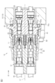
- FIG. 2 is a cross-sectional view of the connector in the embodiment.
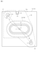
- FIG. 3 is a front view showing a periphery of an opening in the device housing of the embodiment.
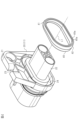
- FIG. 4 is an exploded perspective view showing a first housing and a seal member in the connector of the embodiment.
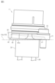
- FIG. 5 is an explanatory diagram for explaining an assembly mode of the connector of the embodiment.
- the connector of the present disclosure comprises: [1] A connector comprising a first connector fixed to an equipment housing, a second connector connected to the first connector, and a sealing member for sealing between the first connector and the equipment housing, wherein the equipment housing has an outer wall having an opening, the first connector has a first housing fixed at a position corresponding to the opening in the outer wall, the second connector has a second housing fitted to the first housing in a fitting direction along an axis of the connector, the first housing has a first fixing portion fixed to the outer wall by a first bolt and a seal mounting groove facing a surface of the outer wall in the fitting direction, the second housing has a second fixing portion fixed to the outer wall by a second bolt attached in the fitting direction, and the seal member attached to the seal mounting groove abuts against the surface of the outer wall in the fitting direction.
- the gap between the first housing and the device housing is sealed by a seal member that abuts against the surface of the outer wall of the device housing in the fitting direction of the second housing. Therefore, it is possible to ensure sealing between the first housing and the device housing regardless of the thickness of the outer wall of the device housing.
- the sealing member may be annular about the axis
- the first housing may have only one first fixed part
- the second housing may have only one second fixed part
- the angle ⁇ [°] between the first fixed part and the second fixed part about the axis may be set within the range of 90° ⁇ ⁇ ⁇ 270°.
- the angle ⁇ between the first and second fixing parts about the axis is set within the range of 90° ⁇ 270°. This makes it possible to abut the seal member against the outer wall in a balanced manner in the circumferential direction due to the fixing forces of the first and second fixing parts against the outer wall. As a result, it is possible to improve the sealing performance of the seal member.
- the angle ⁇ may be set to 180°. According to this configuration, it is possible to bring the seal member into contact with the outer wall in a more balanced manner in the circumferential direction, which makes it possible to further improve the sealing performance of the seal member.
- the sealing member may have a first portion closest to the first fixed portion and a second portion located 180° opposite the first portion with respect to the axis as the center, and the thickness of the sealing member in the direction along the axis may be smallest at the first portion, increase from the first portion to the second portion, and be largest at the second portion.
- annular may refer to any structure that forms a loop, or to continuous shapes with no ends, as well as to generally loop-shaped structures with gaps, such as C-shapes.
- Annular shapes include, but are not limited to, circles, ellipses, and polygons with sharp or rounded corners.
- facing in this specification refers to surfaces or components facing each other, and includes not only cases where they are completely facing each other, but also cases where they are partially facing each other.
- facing in this specification includes both cases where there is a component separate from the two parts between the two parts, and cases where there is nothing between the two parts.
- the connector 10 includes a first connector 11 and a second connector 12.
- the first connector 11 is attached to, for example, an equipment housing 13 of an in-vehicle device.
- the second connector 12 is connected to the first connector 11 attached to the equipment housing 13. Note that only a portion of the equipment housing 13 is illustrated in the drawings.
- the first connector 11 and the second connector 12 are connected to each other along an axis L1 of the connector 10. Note that in the following description, the direction along the axis L1 may be simply referred to as the "axial direction".
- the equipment housing 13 has an outer wall 15 having an opening 14.
- the opening 14 penetrates the outer wall 15. That is, the opening 14 communicates between the inside and the outside of the equipment housing 13.
- the outer wall 15 has a first screw hole 16 and a second screw hole 17.
- a first bolt B1 for attaching the first connector 11 to the outer wall 15 is fixed in the first screw hole 16.
- a second bolt B2 for assisting in connecting the second connector 12 to the first connector 11 is fixed in the second screw hole 17.
- the first bolt B1 and the second bolt B2 are each attached along an axis L1.
- the first connector 11 has a first housing 20 fixed to an outer wall 15 of the device housing 13.
- the first housing 20 is formed of, for example, synthetic resin.
- the first housing 20 includes a first fixing portion 21 and an insertion portion 22.
- only one first fixing portion 21 is provided on the first housing 20.
- the first fixing portion 21 has a first insertion hole 21a through which a first bolt B1 is inserted.
- the first fixing portion 21 is fixed to the outer wall 15 of the device housing 13 by the first bolt B1.
- the first housing 20 has, for example, a positioning recess 23 that fits into the positioning protrusion 18 of the device housing 13.
- the insertion portion 22 is inserted into the opening 14 of the device housing 13 along the axis L1.
- the first housing 20 has a seal mounting groove 24.
- the seal mounting groove 24 is formed in the first housing 20 at a position axially opposed to the surface 15a of the outer wall 15.
- the seal mounting groove 24 is, for example, annular about the axis L1. In other words, the seal mounting groove 24 is annular when viewed in the axial direction.
- the first connector 11 includes a first terminal 25 accommodated inside the first housing 20 and a first electric wire 26 connected to the first terminal 25.
- a plurality of first terminals 25 are provided.
- a plurality of first electric wires 26 are provided corresponding to the number of first terminals 25.
- the first electric wires 26 are pulled out from the insertion portion 22 to the outside of the first housing 20 and enter the inside of the equipment housing 13.
- the first electric wires 26 are electrically connected to an internal component (not shown) provided inside the equipment housing 13.
- the second connector 12 has a second housing 30 that is fitted into the first housing 20.
- the second housing 30 has, for example, an inner housing 31 and an outer housing 32 that partially covers the outside of the inner housing 31.
- the inner housing 31 is formed of, for example, a synthetic resin.
- the outer housing 32 is a shield shell formed of, for example, a metal.
- the inner housing 31 and the outer housing 32 are assembled to each other.
- the outer housing 32 has a second fixing portion 33 that is fixed to the outer wall 15 of the device housing 13 by a second bolt B2 that is attached in the fitting direction D1.
- only one second fixing portion 33 is provided on the second housing 30.
- the second fixing portion 33 has a second insertion hole 33a through which the second bolt B2 is passed.
- the second connector 12 includes a second terminal 34 housed inside the inner housing 31 and a second electric wire 35 connected to the second terminal 34.
- a plurality of second terminals 34 are provided.
- a plurality of second electric wires 35 are provided corresponding to the number of second terminals 34.
- the second housing 30 is fitted into the first housing 20, which is fixed to the outer wall 15, in a fitting direction D1 along the axis L1.
- the second terminal 34 is connected to the first terminal 25. This provides electrical continuity between the first terminal 25 and the second terminal 34.
- the connector 10 includes a seal member 40 that provides a seal between the first connector 11 and the outer wall 15 of the equipment housing 13.
- the seal member 40 is formed of elastic rubber or the like.
- the seal member 40 has an annular shape centered on the axis L1.
- the seal member 40 is attached to the seal attachment groove 24 of the first housing 20.
- the seal member 40 and the seal attachment groove 24 each have an elongated shape extending along a direction perpendicular to the axis L1, for example.
- the seal member 40 has a first portion 41 closest to the first fixed portion 21 and a second portion 42 located 180° opposite to the first portion 41 with respect to the axis L1.
- the thickness of the seal member 40 in the direction along the axis L1 is smallest at the first portion 41, gradually increases from the first portion 41 to the second portion 42, and is largest at the second portion 42.
- the depth of the seal mounting groove 24 in the direction along the axis L1 is smallest at the position corresponding to the first portion 41, gradually increases from the position corresponding to the first portion 41 to the position corresponding to the second portion 42, and is largest at the position corresponding to the second portion 42.
- the protrusion ratio of the seal member 40 from the seal mounting groove 24 is set uniformly over the entire circumferential direction of the seal member 40.
- the protrusion ratio is the ratio of the amount of protrusion of the seal member 40 from the seal mounting groove 24 to the thickness of the seal member 40.
- the seal member 40 abuts against the surface 15a of the outer wall 15 of the device housing 13 in the fitting direction D1. In other words, the seal member 40 is sandwiched between the first housing 20 and the surface 15a of the outer wall 15 in the axial direction.
- the seal member 40 has a lip portion 40a that protrudes toward the surface 15a of the outer wall 15 of the device housing 13.
- the lip portion 40a is formed in an annular shape around the entire circumference of the seal member 40 along the circumferential direction of the seal member 40.
- a pair of lip portions 40a are provided.
- Each lip portion 40a abuts against the surface 15a of the outer wall 15 in the fitting direction D1.
- each lip portion 40a is crushed by abutting against the surface 15a of the outer wall 15.
- each lip portion 40a is in close contact with the surface 15a of the outer wall 15, ensuring sealing properties.
- the protruding length of each lip portion 40a depth of the groove between each lip portion 40a) is set to a uniform length around the entire circumference of the seal member 40, for example.
- the first fixing portion 21 has a first axis CL1.
- the first axis CL1 is parallel to the axis L1 of the connector 10.
- the first axis CL1 coincides with the axis of the first insertion hole 21a and the axis of the first bolt B1.
- the second fixing portion 33 has a second axis CL2.
- the second axis CL2 is parallel to the axis L1 of the connector 10.
- the second axis CL2 coincides with the axis of the second insertion hole 33a and the axis of the second bolt B2.
- the angle between the first axis CL1 and the second axis CL2, which are centered on the axis L1, is ⁇ [°].
- the angle ⁇ is set within the range of 90° ⁇ 270°. Within the above range, the angle ⁇ in this embodiment is set within the range of 170° ⁇ 190°. Furthermore, the angle ⁇ in this embodiment is set to 180° within the range of 170° ⁇ 190°.
- the first fixed portion 21 and the second fixed portion 33 are provided at positions that are point-symmetric with respect to the axis L1.
- the first connector 11 is assembled to the outer wall 15 of the equipment housing 13. More specifically, the first fixing portion 21 of the first housing 20 is fastened to the outer wall 15 by the first bolt B1. At this time, the seal member 40 provided in the seal mounting groove 24 abuts in the axial direction against the surface 15a of the outer wall 15 around the opening 14. That is, the seal member 40 is sandwiched between the seal mounting groove 24 and the surface 15a of the outer wall 15 in the axial direction.
- FIG. 5 shows the state in which the first connector 11 is fixed to the outer wall 15 and before the second connector 12 is attached.
- the first fixing portion 21 is fixed to the surface 15a of the outer wall 15 by the fastening force of the first bolt B1.
- the first fixing portion 21 is the only fixing point of the first housing 20 to the outer wall 15, so as shown in FIG. 5, the 180° opposite side of the first fixing portion 21 on the first housing 20 is raised from the surface 15a of the outer wall 15 by the elasticity of the sealing member 40.
- the above-mentioned thickness setting of the sealing member 40 makes it difficult for a gap to occur between the sealing member 40 and the surface 15a of the outer wall 15.
- the second connector 12 is fitted to the first connector 11 in the fitting direction D1.
- the second fixing portion 33 of the outer housing 32 is fastened to the outer wall 15 by the second bolt B2 to impart a fitting force to the second connector 12 in the fitting direction D1.
- the fastening force of this second bolt B2 causes the portion of the first housing 20 that is raised from the outer wall 15, i.e., the portion 180° opposite the first fixing portion 21, to come into contact with the surface 15a of the outer wall 15.
- the first housing 20 is fixed to the surface 15a of the outer wall 15 with the entire circumferential direction of the seal member 40 compressed in the axial direction.
- the first housing 20 has a first fixing portion 21 fixed to the outer wall 15 by a first bolt B1 and a seal mounting groove 24 facing the surface 15a of the outer wall 15 in the fitting direction D1.
- the second housing 30 has a second fixing portion 33 fixed to the outer wall 15 by a second bolt B2 attached in the fitting direction D1.
- the seal member 40 attached to the seal mounting groove 24 abuts against the surface 15a of the outer wall 15 in the fitting direction D1.
- the first housing 20 and the device housing 13 are sealed by the seal member 40 abutting against the surface 15a of the outer wall 15 of the device housing 13 in the fitting direction D1 of the second housing 30. Therefore, since the configuration does not seal between the insertion portion 22 of the first housing 20 and the inner circumferential surface of the opening 14, it is possible to ensure sealing between the first housing 20 and the outer wall 15 regardless of the thickness of the outer wall 15 of the device housing 13.
- the seal member 40 is annular about the axis L1 of the connector 10.
- the first housing 20 has only one first fixing portion 21.
- the second housing 30 has only one second fixing portion 33.
- the angle ⁇ between the first fixing portion 21 and the second fixing portion 33 about the axis L1 is set within the range of 90° ⁇ 270°.
- the angle ⁇ between the first fixing portion 21 and the second fixing portion 33 about the axis L1 is set within the range of 90° ⁇ 270°. This allows the sealing member 40 to abut against the outer wall 15 in a well-balanced manner in the circumferential direction due to the fixing force of the first fixing portion 21 and the second fixing portion 33 against the outer wall 15. As a result, it is possible to improve the sealing performance of the sealing member 40.
- the angle ⁇ is set within the range of 170° ⁇ 190°. This configuration allows the seal member 40 to abut against the outer wall 15 in a more balanced manner in the circumferential direction. As a result, the sealing performance of the seal member 40 can be further improved.
- the angle ⁇ is set to 180°. This configuration allows the seal member 40 to abut against the outer wall 15 in a more balanced manner in the circumferential direction. As a result, the sealing performance of the seal member 40 can be further improved.
- the seal member 40 has a first portion 41 closest to the first fixing portion 21 and a second portion 42 located 180° opposite the first portion 41 with respect to the axis L1.
- the thickness of the seal member 40 in the direction along the axis L1 is smallest at the first portion 41, increases from the first portion 41 to the second portion 42, and is largest at the second portion 42.
- the thickness of the second portion 42 of the seal member 40 is increased, making it possible to prevent a gap from occurring between the seal member 40 and the outer wall 15 of the device housing 13.
- the outer housing 32 may be omitted from the second housing 30 in the above embodiment.
- the second fixing portion 33 may be provided on the inner housing 31.
- the first housing 20 may include two or more first fixing portions 21.
- the second housing 30 may include two or more second fixing portions 33.
- the thickness of the seal member 40 in the axial direction may be uniform over the entire circumferential direction.
- the angle ⁇ between the first fixed portion 21 (first axis CL1) and the second fixed portion 33 (second axis CL2) centered on the axis L1 may be set within the range of 90° ⁇ 270°.
- the number of the lip portions 40a that come into contact with the surface 15a of the outer wall 15 of the equipment housing 13 may be one or three or more.
- the protruding length of the lip portions 40a in the axial direction may correspond to the thickness of the seal member 40.
- the protruding length of the lip portions 40a may be set to be smallest at a position corresponding to the first portion 41, gradually increase from the position corresponding to the first portion 41 to a position corresponding to the second portion 42, and be largest at the position corresponding to the second portion 42.
- the bolt shaft of the first bolt B1 may only contact the equipment housing 13 (e.g., the first screw hole 16) and the first fixing portion 21 (e.g., the first insertion hole 21a) of the first connector 11, and the bolt shaft of the second bolt B2 may only contact the equipment housing 13 (e.g., the second screw hole 17) and the second fixing portion 33 (e.g., the second insertion hole 33a) of the second connector 12, and the bolt shaft of the first bolt B1 may not contact the second connector 12, and the bolt shaft of the second bolt B2 may not contact the first connector 11.
- the surface 15a of the outer wall 15 of the equipment housing 13 may be referred to as a support surface or seat surface that supports the connector 10.
- This seat surface may be a plane perpendicular to the axis L1 of the connector 10.
- the first connector 11 of the embodiment may include a stopper flange that is perpendicular to the axis L1 of the connector 10 and/or extends parallel to the surface 15a of the equipment housing 13, an insertion portion 22 perpendicular to the stopper flange, and a cylindrical hood that accommodates the first terminal 25 and is perpendicular to the stopper flange.
- the first fixing portion 21 of the first connector 11 may be included in the stopper flange, or may be included in a stopper tab that further protrudes radially from the stopper flange.
- the stopper flange and/or the stopper tab may include a stopper surface that is perpendicular to the axis L1 of the connector 10 and/or that can directly contact the surface 15a of the equipment housing 13.
- the first insertion hole 21a (first axis CL1) of the first connector 11 can be provided only at a first angular position around the axis L1 of the connector 10 in the first connector 11.
- Figs. 1 the first insertion hole 21a (first axis CL1) of the first connector 11 can be provided only at a first angular position around the axis L1 of the connector 10 in the first connector 11.
- the second insertion hole 33a (second axis CL2) of the second connector 12 can be provided only at a second angular position around the axis L1 of the connector 10 in the second connector 12.
- the first portion 41 of the seal member 40 may be at or near the first angular position around the axis L1 of the connector 10
- the second portion 42 of the seal member 40 may be at or near the second angular position around the axis L1 of the connector 10.
- the seal mounting groove 24 of the first connector 11 may be referred to as an annular groove having a groove opening on the stopper surface of the first connector 11 and having a non-uniform groove depth.
Landscapes
- Connector Housings Or Holding Contact Members (AREA)
Abstract
第1コネクタ(11)は、機器ハウジング(13)の外壁(15)における開口部(14)に対応する位置に固定される第1ハウジング(20)を有する。第2コネクタ(12)は、第1ハウジング(20)に対して、コネクタ(10)の軸線(L1)に沿った嵌合方向(D1)に嵌合される第2ハウジング(30)を有する。第1ハウジング(20)は、第1ボルトによって外壁(15)に固定される第1固定部と、嵌合方向(D1)において外壁(15)の表面(15a)に対向するシール取付溝(24)とを有する。第2ハウジング(30)は、嵌合方向(D1)に装着される第2ボルト(B2)によって外壁(15)に固定される第2固定部(33)を有する。シール取付溝(24)に取り付けられたシール部材(40)は、嵌合方向(D1)において外壁(15)の表面(15a)に当接する。
Description
本開示は、コネクタに関するものである。
特許文献1には、機器ハウジングに固定される第1コネクタと、第1コネクタに接続される第2コネクタと、第1コネクタと機器ハウジングとの間をシールするシール部材とを備えるコネクタが開示されている。機器ハウジングは、開口部を有する外壁を備える。第1コネクタは、外壁における開口部に対応する位置に固定される第1ハウジングを有する。第2コネクタは、機器ハウジングの外壁に固定された第1ハウジングに嵌合される第2ハウジングを有する。第2ハウジングは、第1ハウジングに嵌合された状態で、ボルトによって機器ハウジングの外壁に固定される。このボルトによる固定により、第1コネクタに対する第2コネクタの接続が補助される。また、第1ハウジングは、機器ハウジングの外壁の開口部に挿入される挿入部を有する。シール部材は、挿入部の外周面と外壁の開口部の内周面との間に介在されている。これにより、シール部材によって機器ハウジング内に水が浸入しないようにシールされている。
機器ハウジングの外壁の厚さを薄くした場合、外壁を貫通する開口部の貫通長さを確保することが難しい。開口部の貫通長さが短いと、第1ハウジングの挿入部と開口部との間に介在されるシール部材のシール性を確保できなくなるおそれがある。
本開示の目的は、機器ハウジングの外壁の厚さに関わらずシール性を確保することを可能としたコネクタを提供することにある。
本開示のコネクタは、機器ハウジングに固定される第1コネクタと、前記第1コネクタに接続される第2コネクタと、前記第1コネクタと前記機器ハウジングとの間をシールするシール部材と、を備えるコネクタであって、前記機器ハウジングは、開口部を有する外壁を備え、前記第1コネクタは、前記外壁における前記開口部に対応する位置に固定される第1ハウジングを有し、前記第2コネクタは、前記第1ハウジングに対して、前記コネクタの軸線に沿った嵌合方向に嵌合される第2ハウジングを有し、前記第1ハウジングは、第1ボルトによって前記外壁に固定される第1固定部と、前記嵌合方向において前記外壁の表面に対向するシール取付溝と、を有し、前記第2ハウジングは、前記嵌合方向に装着される第2ボルトによって前記外壁に固定される第2固定部を有し、前記シール取付溝に取り付けられた前記シール部材は、前記嵌合方向において前記外壁の前記表面に当接する。
本開示のコネクタによれば、機器ハウジングの外壁の厚さに関わらずシール性を確保することが可能となる。
[本開示の実施形態の説明]
最初に本開示の実施態様を列記して説明する。
本開示のコネクタは、
[1]機器ハウジングに固定される第1コネクタと、前記第1コネクタに接続される第2コネクタと、前記第1コネクタと前記機器ハウジングとの間をシールするシール部材と、を備えるコネクタであって、前記機器ハウジングは、開口部を有する外壁を備え、前記第1コネクタは、前記外壁における前記開口部に対応する位置に固定される第1ハウジングを有し、前記第2コネクタは、前記第1ハウジングに対して、前記コネクタの軸線に沿った嵌合方向に嵌合される第2ハウジングを有し、前記第1ハウジングは、第1ボルトによって前記外壁に固定される第1固定部と、前記嵌合方向において前記外壁の表面に対向するシール取付溝と、を有し、前記第2ハウジングは、前記嵌合方向に装着される第2ボルトによって前記外壁に固定される第2固定部を有し、前記シール取付溝に取り付けられた前記シール部材は、前記嵌合方向において前記外壁の前記表面に当接する。
この構成によれば、機器ハウジングの外壁の表面に対して第2ハウジングの嵌合方向に当接するシール部材によって、第1ハウジングと機器ハウジングとの間がシールされる。したがって、機器ハウジングの外壁の厚さに関わらず、第1ハウジングと機器ハウジングとの間のシール性を確保することが可能となる。
[2]上記[1]において、前記シール部材は、前記軸線を中心とする環状をなし、前記第1ハウジングは、前記第1固定部を1つのみ有し、前記第2ハウジングは、前記第2固定部を1つのみ有し、前記軸線を中心とする前記第1固定部と前記第2固定部との間の角度θ[°]は、90°<θ<270°の範囲内に設定されていてもよい。
この構成によれば、第1固定部および第2固定部がそれぞれ1つのみであるため、コネクタの組付作業におけるボルト固定の工数を少なく抑えることが可能となる。そして、軸線を中心とする第1固定部と第2固定部との間の角度θは、90°<θ<270°の範囲内に設定される。これにより、第1固定部および第2固定部の外壁に対する固定力によって、シール部材を周方向においてバランス良く外壁に当接させることが可能となる。その結果、シール部材のシール性を向上させることが可能となる。
[3]上記[2]において、前記角度θは、180°に設定されていてもよい。
この構成によれば、シール部材を周方向においてよりバランス良く外壁に当接させることが可能となる。その結果、シール部材のシール性をより向上させることが可能となる。
この構成によれば、シール部材を周方向においてよりバランス良く外壁に当接させることが可能となる。その結果、シール部材のシール性をより向上させることが可能となる。
[4]上記[2]または[3]において、前記シール部材は、前記第1固定部に最も近い第1部位と、前記軸線を中心として前記第1部位の180°反対位置にある第2部位と、を有し、前記軸線に沿った方向における前記シール部材の厚さは、前記第1部位で最も小さく、前記第1部位から前記第2部位にかけて大きくなり、前記第2部位で最も大きい構成であってもよい。
この構成によれば、第2コネクタを接続する前の状態において、第1ハウジングにおける第1固定部の180°反対側が機器ハウジングの外壁から浮き上がるおそれがある。このような状態になっても、上記構成では、シール部材における第2部位の厚さを大きくしているため、シール部材と機器ハウジングの外壁との間に隙間が生じることを抑制することが可能となる。
[本開示の実施形態の詳細]
本開示のコネクタの具体例を、以下に図面を参照しつつ説明する。各図面では、説明の便宜上、構成の一部を誇張または簡略化して示す場合がある。また、各部分の寸法比率については各図面で異なる場合がある。また、本明細書における「平行」は、厳密に平行やの場合のみでなく、本実施形態における作用ならびに効果を奏する範囲内で概ね平行の場合も含まれる。
本開示のコネクタの具体例を、以下に図面を参照しつつ説明する。各図面では、説明の便宜上、構成の一部を誇張または簡略化して示す場合がある。また、各部分の寸法比率については各図面で異なる場合がある。また、本明細書における「平行」は、厳密に平行やの場合のみでなく、本実施形態における作用ならびに効果を奏する範囲内で概ね平行の場合も含まれる。
なお、本明細書の説明で使用される「環状」という用語は、ループを形成する任意の構造、または端部のない連続形状、並びに、C字形のようなギャップを有する、一般的にループ形状の構造を指すことがある。なお、「環状」の形状には、円形、楕円形、及び、尖ったまたは丸い角を有する多角形が含まれるが、これらに限定されない。
また、本明細書における「対向」とは、面同士又は部材同士が互いに正面の位置にあることを指し、互いが完全に正面の位置にある場合だけでなく、互いが部分的に正面の位置にある場合を含む。また、本明細書における「対向」とは、2つの部分の間に、2つの部分とは別の部材が介在している場合と、2つの部分の間に何も介在していない場合の両方を含む。
(コネクタ10)
図1に示すように、コネクタ10は、第1コネクタ11と、第2コネクタ12とを備える。第1コネクタ11は、例えば車載機器の機器ハウジング13に取り付けられる。第2コネクタ12は、機器ハウジング13に取り付けられた第1コネクタ11に接続される。なお、図面では、機器ハウジング13の一部のみを図示している。第1コネクタ11と第2コネクタ12とは、コネクタ10の軸線L1に沿って互いに接続される。なお、以下の説明では、軸線L1に沿った方向について、単に「軸方向」と称する場合がある。
図1に示すように、コネクタ10は、第1コネクタ11と、第2コネクタ12とを備える。第1コネクタ11は、例えば車載機器の機器ハウジング13に取り付けられる。第2コネクタ12は、機器ハウジング13に取り付けられた第1コネクタ11に接続される。なお、図面では、機器ハウジング13の一部のみを図示している。第1コネクタ11と第2コネクタ12とは、コネクタ10の軸線L1に沿って互いに接続される。なお、以下の説明では、軸線L1に沿った方向について、単に「軸方向」と称する場合がある。
(機器ハウジング13)
図1および図3に示すように、機器ハウジング13は、開口部14を有する外壁15を有する。開口部14は、外壁15を貫通している。すなわち、開口部14は、機器ハウジング13の内外を連通している。外壁15は、第1ねじ穴16と、第2ねじ穴17とを有する。第1ねじ穴16には、第1コネクタ11を外壁15に取り付けるための第1ボルトB1が固定される。第2ねじ穴17には、第1コネクタ11に対する第2コネクタ12の接続を補助する第2ボルトB2が固定される。第1ボルトB1および第2ボルトB2はそれぞれ、軸線L1に沿って取り付けられる。
図1および図3に示すように、機器ハウジング13は、開口部14を有する外壁15を有する。開口部14は、外壁15を貫通している。すなわち、開口部14は、機器ハウジング13の内外を連通している。外壁15は、第1ねじ穴16と、第2ねじ穴17とを有する。第1ねじ穴16には、第1コネクタ11を外壁15に取り付けるための第1ボルトB1が固定される。第2ねじ穴17には、第1コネクタ11に対する第2コネクタ12の接続を補助する第2ボルトB2が固定される。第1ボルトB1および第2ボルトB2はそれぞれ、軸線L1に沿って取り付けられる。
(第1コネクタ11)
図1に示すように、第1コネクタ11は、機器ハウジング13の外壁15に固定される第1ハウジング20を有している。第1ハウジング20は、例えば合成樹脂にて形成されている。第1ハウジング20は、第1固定部21と、挿入部22とを備える。第1固定部21は、第1ハウジング20に例えば1つのみ設けられている。第1固定部21は、第1ボルトB1が通される第1挿通孔21aを有している。第1固定部21は、第1ボルトB1によって機器ハウジング13の外壁15に固定される。なお、第1ハウジング20は、例えば、機器ハウジング13の位置決め凸部18に嵌まる位置決め凹部23を有している。挿入部22は、機器ハウジング13の開口部14に軸線L1に沿って挿入される。
図1に示すように、第1コネクタ11は、機器ハウジング13の外壁15に固定される第1ハウジング20を有している。第1ハウジング20は、例えば合成樹脂にて形成されている。第1ハウジング20は、第1固定部21と、挿入部22とを備える。第1固定部21は、第1ハウジング20に例えば1つのみ設けられている。第1固定部21は、第1ボルトB1が通される第1挿通孔21aを有している。第1固定部21は、第1ボルトB1によって機器ハウジング13の外壁15に固定される。なお、第1ハウジング20は、例えば、機器ハウジング13の位置決め凸部18に嵌まる位置決め凹部23を有している。挿入部22は、機器ハウジング13の開口部14に軸線L1に沿って挿入される。
図2および図4に示すように、第1ハウジング20は、シール取付溝24を備える。シール取付溝24は、第1ハウジング20において、外壁15の表面15aに対して軸方向に対向する位置に形成されている。シール取付溝24は、例えば、軸線L1を中心とする環状をなしている。すなわち、シール取付溝24は、軸方向視で環状をなしている。
図2に示すように、第1コネクタ11は、第1ハウジング20の内部に収容された第1端子25と、第1端子25に接続された第1電線26とを備える。第1端子25は、例えば複数設けられている。第1電線26は、第1端子25の数に対応して例えば複数設けられている。第1電線26は、挿入部22から第1ハウジング20の外部に引き出されるとともに、機器ハウジング13の内部に入り込んでいる。そして、第1電線26は、機器ハウジング13の内部に設けられる図示しない内部部品に電気的に接続される。
(第2コネクタ12)
図1に示すように、第2コネクタ12は、第1ハウジング20に嵌合される第2ハウジング30を有している。第2ハウジング30は、例えば、インナーハウジング31と、インナーハウジング31の外側を部分的に覆うアウターハウジング32とを有している。インナーハウジング31は、例えば合成樹脂にて形成されている。アウターハウジング32は、例えば金属にて形成されたシールドシェルである。インナーハウジング31とアウターハウジング32とは、互いに組み付けられている。アウターハウジング32は、嵌合方向D1に装着される第2ボルトB2によって機器ハウジング13の外壁15に固定される第2固定部33を有している。第2固定部33は、第2ハウジング30に例えば1つのみ設けられている。第2固定部33は、第2ボルトB2が通される第2挿通孔33aを有している。
図1に示すように、第2コネクタ12は、第1ハウジング20に嵌合される第2ハウジング30を有している。第2ハウジング30は、例えば、インナーハウジング31と、インナーハウジング31の外側を部分的に覆うアウターハウジング32とを有している。インナーハウジング31は、例えば合成樹脂にて形成されている。アウターハウジング32は、例えば金属にて形成されたシールドシェルである。インナーハウジング31とアウターハウジング32とは、互いに組み付けられている。アウターハウジング32は、嵌合方向D1に装着される第2ボルトB2によって機器ハウジング13の外壁15に固定される第2固定部33を有している。第2固定部33は、第2ハウジング30に例えば1つのみ設けられている。第2固定部33は、第2ボルトB2が通される第2挿通孔33aを有している。
図2に示すように、第2コネクタ12は、インナーハウジング31の内部に収容された第2端子34と、第2端子34に接続された第2電線35とを備える。第2端子34は、例えば複数設けられている。第2電線35は、第2端子34の数に対応して例えば複数設けられている。
第2ハウジング30は、外壁15に固定された第1ハウジング20に対して、軸線L1に沿った嵌合方向D1に嵌合される。第2ハウジング30が第1ハウジング20に嵌合された状態において、第2端子34は第1端子25に接続される。これにより、第1端子25と第2端子34とが電気的に導通される。
(シール部材40)
図2に示すように、コネクタ10は、第1コネクタ11と機器ハウジング13の外壁15との間をシールするシール部材40を備える。シール部材40は、弾性を有するゴム等によって形成されている。図2および図4に示すように、シール部材40は、軸線L1を中心とする環状をなしている。シール部材40は、第1ハウジング20のシール取付溝24に取り付けられる。シール部材40およびシール取付溝24は、例えば、軸線L1と直交する一方向に沿って長い形状をなしている。
図2に示すように、コネクタ10は、第1コネクタ11と機器ハウジング13の外壁15との間をシールするシール部材40を備える。シール部材40は、弾性を有するゴム等によって形成されている。図2および図4に示すように、シール部材40は、軸線L1を中心とする環状をなしている。シール部材40は、第1ハウジング20のシール取付溝24に取り付けられる。シール部材40およびシール取付溝24は、例えば、軸線L1と直交する一方向に沿って長い形状をなしている。
図4に示すように、シール部材40は、第1固定部21に最も近い第1部位41と、軸線L1を中心として第1部位41の180°反対位置にある第2部位42とを有している。軸線L1に沿った方向におけるシール部材40の厚さは、第1部位41で最も小さく、第1部位41から第2部位42にかけて徐々に大きくなり、第2部位42で最も大きくなっている。また、例えば、軸線L1に沿った方向におけるシール取付溝24の深さは、第1部位41に対応する位置で最も小さく、第1部位41に対応する位置から第2部位42に対応する位置にかけて徐々に大きくなり、第2部位42に対応する位置で最も大きくなっている。また、シール取付溝24からのシール部材40の突出比率は、シール部材40の周方向全体にわたって一様に設定されている。なお、前記突出比率とは、シール部材40の厚さに対するシール取付溝24からのシール部材40の突出量の比率である。
図2に示すように、シール部材40は、嵌合方向D1において機器ハウジング13の外壁15の表面15aに当接する。すなわち、シール部材40は、軸方向において、第1ハウジング20と外壁15の表面15aとによって挟まれている。
シール部材40は、機器ハウジング13における外壁15の表面15aに向かって突出するリップ部40aを備える。リップ部40aは、シール部材40の周方向に沿って、シール部材40の全周にわたって環状に形成されている。リップ部40aは、例えば一対設けられている。各リップ部40aは、嵌合方向D1において外壁15の表面15aに当接する。シール部材40が第1ハウジング20と外壁15の表面15aとに挟まれた状態において、各リップ部40aは、外壁15の表面15aとの当接により潰れる。これにより、各リップ部40aが外壁15の表面15aに密着し、シール性が確保される。なお、各リップ部40aの突出長さ(各リップ部40aの間の溝の深さ)は、例えば、シール部材40の全周にわたって一様な長さに設定されている。
(第1固定部21および第2固定部33の詳細)
図3に示すように、第1固定部21は、第1軸線CL1を有する。第1軸線CL1は、コネクタ10の軸線L1に対して平行をなす。第1軸線CL1は、第1挿通孔21aの軸線および第1ボルトB1の軸線の各々と一致する。
図3に示すように、第1固定部21は、第1軸線CL1を有する。第1軸線CL1は、コネクタ10の軸線L1に対して平行をなす。第1軸線CL1は、第1挿通孔21aの軸線および第1ボルトB1の軸線の各々と一致する。
第2固定部33は、第2軸線CL2を有する。第2軸線CL2は、コネクタ10の軸線L1に対して平行をなす。第2軸線CL2は、第2挿通孔33aの軸線および第2ボルトB2の軸線の各々と一致する。
図3に示すように、軸線L1を中心とする第1軸線CL1と第2軸線CL2との間の角度をθ[°]とする。当該角度θは、90°<θ<270°の範囲内に設定されている。本実施形態の角度θは、上記範囲の中でも、170°<θ<190°の範囲内に設定されている。さらに、本実施形態の角度θは、170°<θ<190°の範囲の中でも180°に設定されている。すなわち、第1固定部21と第2固定部33とは、軸線L1を中心として点対称となる位置に設けられている。
本実施形態の作用について説明する。
コネクタ10の組み付けの際には、まず、第1コネクタ11を機器ハウジング13の外壁15に組み付ける。詳しくは、第1ハウジング20の第1固定部21を第1ボルトB1によって外壁15に締結固定する。このとき、シール取付溝24に設けられたシール部材40は、開口部14の周囲における外壁15の表面15aに対して軸方向に当接する。すなわち、シール部材40は、軸方向においてシール取付溝24と外壁15の表面15aとの間に挟まれる。
コネクタ10の組み付けの際には、まず、第1コネクタ11を機器ハウジング13の外壁15に組み付ける。詳しくは、第1ハウジング20の第1固定部21を第1ボルトB1によって外壁15に締結固定する。このとき、シール取付溝24に設けられたシール部材40は、開口部14の周囲における外壁15の表面15aに対して軸方向に当接する。すなわち、シール部材40は、軸方向においてシール取付溝24と外壁15の表面15aとの間に挟まれる。
図5には、第1コネクタ11が外壁15に固定され、かつ、第2コネクタ12が取り付けられる前の状態を示している。この状態では、第1ボルトB1の締結力によって第1固定部21が外壁15の表面15aに固定される。このとき、外壁15に対する第1ハウジング20の固定点が第1固定部21の1つのみであるため、図5に示すように、第1ハウジング20における第1固定部21の180°反対側が、シール部材40の弾性によって外壁15の表面15aから浮き上がる。このような状態となっても、本実施形態では、シール部材40の上記の厚さ設定によって、シール部材40と外壁15の表面15aとの間に隙間が生じにくくなっている。
第1コネクタ11を外壁15に取り付けた後、第2コネクタ12を第1コネクタ11に対して嵌合方向D1に嵌合させる。このとき、第2コネクタ12に対して嵌合方向D1への嵌合力を付与すべく、アウターハウジング32の第2固定部33を第2ボルトB2によって外壁15に締結固定する。この第2ボルトB2の締結力によって、第1ハウジング20における外壁15から浮き上がった部分、すなわち、第1固定部21の180°反対側の部分が外壁15の表面15aに接する。このように、第1固定部21および第2固定部33がそれぞれ第1ボルトB1および第2ボルトB2によって締結されることにより、第1ハウジング20が、シール部材40の周方向全体を軸方向に圧縮させた状態で、外壁15の表面15aに固定される。
本実施形態の効果について説明する。
(1)第1ハウジング20は、第1ボルトB1によって外壁15に固定される第1固定部21と、嵌合方向D1において外壁15の表面15aに対向するシール取付溝24とを有する。第2ハウジング30は、嵌合方向D1に装着される第2ボルトB2によって外壁15に固定される第2固定部33を有する。そして、シール取付溝24に取り付けられたシール部材40は、嵌合方向D1において外壁15の表面15aに当接する。この構成によれば、機器ハウジング13の外壁15の表面15aに対して第2ハウジング30の嵌合方向D1に当接するシール部材40によって、第1ハウジング20と機器ハウジング13との間がシールされる。したがって、第1ハウジング20の挿入部22と開口部14の内周面との間でシールをする構成ではないため、機器ハウジング13の外壁15の厚さに関わらず、第1ハウジング20と外壁15との間のシール性を確保することが可能となる。
(1)第1ハウジング20は、第1ボルトB1によって外壁15に固定される第1固定部21と、嵌合方向D1において外壁15の表面15aに対向するシール取付溝24とを有する。第2ハウジング30は、嵌合方向D1に装着される第2ボルトB2によって外壁15に固定される第2固定部33を有する。そして、シール取付溝24に取り付けられたシール部材40は、嵌合方向D1において外壁15の表面15aに当接する。この構成によれば、機器ハウジング13の外壁15の表面15aに対して第2ハウジング30の嵌合方向D1に当接するシール部材40によって、第1ハウジング20と機器ハウジング13との間がシールされる。したがって、第1ハウジング20の挿入部22と開口部14の内周面との間でシールをする構成ではないため、機器ハウジング13の外壁15の厚さに関わらず、第1ハウジング20と外壁15との間のシール性を確保することが可能となる。
(2)シール部材40は、コネクタ10の軸線L1を中心とする環状をなす。第1ハウジング20は、第1固定部21を1つのみ有する。第2ハウジング30は、第2固定部33を1つのみ有する。軸線L1を中心とする第1固定部21と第2固定部33との間の角度θは、90°<θ<270°の範囲内に設定されている。この構成によれば、第1固定部21および第2固定部33がそれぞれ1つのみであるため、コネクタ10の組付作業におけるボルト固定の工数を少なく抑えることが可能となる。また、第1固定部21および第2固定部33がそれぞれ1つのみであることから、軸線L1と直交する径方向における第1ハウジング20および第2ハウジング30の小型化に寄与できる。そして、軸線L1を中心とする第1固定部21と第2固定部33との間の角度θは、90°<θ<270°の範囲内に設定される。これにより、第1固定部21および第2固定部33の外壁15に対する固定力によって、シール部材40を周方向においてバランス良く外壁15に当接させることが可能となる。その結果、シール部材40のシール性を向上させることが可能となる。
(3)角度θは、170°<θ<190°の範囲内に設定されている。この構成によれば、シール部材40を周方向においてよりバランス良く外壁15に当接させることが可能となる。その結果、シール部材40のシール性をより向上させることが可能となる。
(4)角度θは、180°に設定されている。この構成によれば、シール部材40を周方向においてさらにバランス良く外壁15に当接させることが可能となる。その結果、シール部材40のシール性をさらに向上させることが可能となる。
(5)シール部材40は、第1固定部21に最も近い第1部位41と、軸線L1を中心として第1部位41の180°反対位置にある第2部位42と、を有する。軸線L1に沿った方向におけるシール部材40の厚さは、第1部位41で最も小さく、第1部位41から第2部位42にかけて大きくなり、第2部位42で最も大きい構成とされる。第2コネクタ12を接続する前の状態において、第1ハウジング20における第1固定部21の180°反対側が機器ハウジング13の外壁15から浮き上がるおそれがある。このような状態になっても、上記構成では、シール部材40における第2部位42の厚さを大きくしているため、シール部材40と機器ハウジング13の外壁15との間に隙間が生じることを抑制することが可能となる。
(変更例)
本実施形態は、以下のように変更して実施することができる。本実施形態及び以下の変更例は、技術的に矛盾しない範囲で互いに組み合わせて実施することができる。
本実施形態は、以下のように変更して実施することができる。本実施形態及び以下の変更例は、技術的に矛盾しない範囲で互いに組み合わせて実施することができる。
・上記実施形態の第2ハウジング30からアウターハウジング32を省略してもよい。この場合、第2固定部33は、インナーハウジング31に設けられていてもよい。
・第1ハウジング20は、第1固定部21を2つ以上備えていてもよい。また、第2ハウジング30は、第2固定部33を2つ以上備えていてもよい。
・第1ハウジング20は、第1固定部21を2つ以上備えていてもよい。また、第2ハウジング30は、第2固定部33を2つ以上備えていてもよい。
・シール部材40の軸方向における厚さは、周方向全体にわたって一様であってもよい。
・上記実施形態において、軸線L1を中心とする第1固定部21(第1軸線CL1)と第2固定部33(第2軸線CL2)との間の角度θは、90°<θ<270°の範囲内に設定されていればよい。
・上記実施形態において、軸線L1を中心とする第1固定部21(第1軸線CL1)と第2固定部33(第2軸線CL2)との間の角度θは、90°<θ<270°の範囲内に設定されていればよい。
・上記実施形態のシール部材40において、機器ハウジング13の外壁15の表面15aに当接するリップ部40aの数は、1つまたは3つ以上であってもよい。
・上記実施形態のシール部材40において、軸方向におけるリップ部40aの突出長さ(各リップ部40aの間の溝の深さ)をシール部材40の厚さに対応させてもよい。すなわち、リップ部40aの突出長さは、第1部位41に対応する位置で最も小さく、第1部位41に対応する位置から第2部位42に対応する位置にかけて徐々に大きくなり、第2部位42に対応する位置で最も大きくなるように設定されていてもよい。
・上記実施形態のシール部材40において、軸方向におけるリップ部40aの突出長さ(各リップ部40aの間の溝の深さ)をシール部材40の厚さに対応させてもよい。すなわち、リップ部40aの突出長さは、第1部位41に対応する位置で最も小さく、第1部位41に対応する位置から第2部位42に対応する位置にかけて徐々に大きくなり、第2部位42に対応する位置で最も大きくなるように設定されていてもよい。
・図2、3に示すように、実施形態のコネクタ10が第1ボルトB1および第2ボルトB2によって機器ハウジング13に締結されたとき、第1ボルトB1のボルトシャフトは、機器ハウジング13(例えば第1ねじ穴16)および第1コネクタ11の第1固定部21(例えば第1挿通孔21a)のみと接触してよく、かつ、第2ボルトB2のボルトシャフトは、機器ハウジング13(例えば第2ねじ穴17)および第2コネクタ12の第2固定部33(例えば第2挿通孔33a)のみと接触してよく、かつ、第1ボルトB1のボルトシャフトは、第2コネクタ12とは接触しなくてよく、かつ、第2ボルトB2のボルトシャフトは、第1コネクタ11とは接触しなくてよい。
・図1に示した実施形態において、機器ハウジング13の外壁15の表面15aは、コネクタ10を支持する支持面または座面として参照することがある。この座面は、コネクタ10の軸線L1に対して直交する平面であり得る。図1に示すように、実施形態の第1コネクタ11は、コネクタ10の軸線L1に対して直交する、および/または、機器ハウジング13の表面15aに対して平行に広がるストッパフランジと、このストッパフランジに直交する挿入部22と、第1端子25を収容しストッパフランジに直交する筒状フードとを含むことができる。第1コネクタ11の第1固定部21は、ストッパフランジに含まれてよく、または、ストッパフランジからさらに径方向に突出するストッパタブに含まれてもよい。ストッパフランジおよび/またはストッパタブは、コネクタ10の軸線L1に対して直交する、および/または、機器ハウジング13の表面15aに直接接触可能なストッパ面を含むことができる。図1、3に示すように、第1コネクタ11の第1挿通孔21a(第1軸線CL1)は、第1コネクタ11において、コネクタ10の軸線L1の周りの第1の角度位置にのみ設けられることができる。図1、3に示すように、第2コネクタ12の第2挿通孔33a(第2軸線CL2)は、第2コネクタ12において、コネクタ10の軸線L1の周りの第2の角度位置にのみ設けられることができる。図3に示すように、シール部材40の第1部位41は、コネクタ10の軸線L1の周りの前記第1の角度位置またはその近傍であってよく、シール部材40の第2部位42は、コネクタ10の軸線L1の周りの前記第2の角度位置またはその近傍であってよい。図4に示すように、第1コネクタ11のシール取付溝24は、第1コネクタ11のストッパ面に溝開口を有し、不均一な溝深さを有する環状溝として参照することがある。
・今回開示された実施形態及び変更例はすべての点で例示であって、本発明はこれらの例示に限定されるものではない。すなわち、本発明の範囲は、特許請求の範囲によって示され、特許請求の範囲と均等の意味及び範囲内でのすべての変更が含まれることが意図される。
10 コネクタ
11 第1コネクタ
12 第2コネクタ
13 機器ハウジング
14 開口部
15 外壁
15a 表面
16 第1ねじ穴
17 第2ねじ穴
18 位置決め凸部
20 第1ハウジング
21 第1固定部
21a 第1挿通孔
22 挿入部
23 位置決め凹部
24 シール取付溝
25 第1端子
26 第1電線
30 第2ハウジング
31 インナーハウジング
32 アウターハウジング
33 第2固定部
33a 第2挿通孔
34 第2端子
35 第2電線
40 シール部材
40a リップ部
41 第1部位
42 第2部位
θ 角度
B1 第1ボルト
B2 第2ボルト
CL1 第1軸線
CL2 第2軸線
D1 嵌合方向
L1 コネクタの軸線
Claims (4)
- 機器ハウジングに固定される第1コネクタと、
前記第1コネクタに接続される第2コネクタと、
前記第1コネクタと前記機器ハウジングとの間をシールするシール部材と、
を備えるコネクタであって、
前記機器ハウジングは、開口部を有する外壁を備え、
前記第1コネクタは、前記外壁における前記開口部に対応する位置に固定される第1ハウジングを有し、
前記第2コネクタは、前記第1ハウジングに対して、前記コネクタの軸線に沿った嵌合方向に嵌合される第2ハウジングを有し、
前記第1ハウジングは、第1ボルトによって前記外壁に固定される第1固定部と、前記嵌合方向において前記外壁の表面に対向するシール取付溝と、を有し、
前記第2ハウジングは、前記嵌合方向に装着される第2ボルトによって前記外壁に固定される第2固定部を有し、
前記シール取付溝に取り付けられた前記シール部材は、前記嵌合方向において前記外壁の前記表面に当接する、
コネクタ。 - 前記シール部材は、前記軸線を中心とする環状をなし、
前記第1ハウジングは、前記第1固定部を1つのみ有し、
前記第2ハウジングは、前記第2固定部を1つのみ有し、
前記軸線を中心とする前記第1固定部と前記第2固定部との間の角度θ[°]は、90°<θ<270°の範囲内に設定されている、
請求項1に記載のコネクタ。 - 前記角度θは、180°に設定されている、
請求項2に記載のコネクタ。 - 前記シール部材は、前記第1固定部に最も近い第1部位と、前記軸線を中心として前記第1部位の180°反対位置にある第2部位と、を有し、
前記軸線に沿った方向における前記シール部材の厚さは、前記第1部位で最も小さく、前記第1部位から前記第2部位にかけて大きくなり、前記第2部位で最も大きい、
請求項2または3に記載のコネクタ。
Applications Claiming Priority (2)
| Application Number | Priority Date | Filing Date | Title |
|---|---|---|---|
| JP2023116038A JP2025012873A (ja) | 2023-07-14 | 2023-07-14 | コネクタ |
| JP2023-116038 | 2023-07-14 |
Publications (1)
| Publication Number | Publication Date |
|---|---|
| WO2025018293A1 true WO2025018293A1 (ja) | 2025-01-23 |
Family
ID=94281525
Family Applications (1)
| Application Number | Title | Priority Date | Filing Date |
|---|---|---|---|
| PCT/JP2024/025254 Ceased WO2025018293A1 (ja) | 2023-07-14 | 2024-07-12 | コネクタ |
Country Status (2)
| Country | Link |
|---|---|
| JP (1) | JP2025012873A (ja) |
| WO (1) | WO2025018293A1 (ja) |
Citations (5)
| Publication number | Priority date | Publication date | Assignee | Title |
|---|---|---|---|---|
| JPH06281014A (ja) * | 1993-03-24 | 1994-10-07 | Shin Kobe Electric Mach Co Ltd | ガスケットの製造法 |
| JP2012216336A (ja) * | 2011-03-31 | 2012-11-08 | Yazaki Corp | シールドコネクタ |
| JP2013054929A (ja) * | 2011-09-05 | 2013-03-21 | Sumitomo Wiring Syst Ltd | 機器用コネクタ |
| JP2015125865A (ja) * | 2013-12-26 | 2015-07-06 | 株式会社オートネットワーク技術研究所 | コネクタ |
| JP2021128911A (ja) * | 2020-02-17 | 2021-09-02 | 住友電装株式会社 | コネクタおよびコネクタ用シール部材 |
-
2023
- 2023-07-14 JP JP2023116038A patent/JP2025012873A/ja active Pending
-
2024
- 2024-07-12 WO PCT/JP2024/025254 patent/WO2025018293A1/ja not_active Ceased
Patent Citations (5)
| Publication number | Priority date | Publication date | Assignee | Title |
|---|---|---|---|---|
| JPH06281014A (ja) * | 1993-03-24 | 1994-10-07 | Shin Kobe Electric Mach Co Ltd | ガスケットの製造法 |
| JP2012216336A (ja) * | 2011-03-31 | 2012-11-08 | Yazaki Corp | シールドコネクタ |
| JP2013054929A (ja) * | 2011-09-05 | 2013-03-21 | Sumitomo Wiring Syst Ltd | 機器用コネクタ |
| JP2015125865A (ja) * | 2013-12-26 | 2015-07-06 | 株式会社オートネットワーク技術研究所 | コネクタ |
| JP2021128911A (ja) * | 2020-02-17 | 2021-09-02 | 住友電装株式会社 | コネクタおよびコネクタ用シール部材 |
Also Published As
| Publication number | Publication date |
|---|---|
| JP2025012873A (ja) | 2025-01-24 |
Similar Documents
| Publication | Publication Date | Title |
|---|---|---|
| US9160097B2 (en) | Connector with small housing | |
| JP7055783B2 (ja) | 嵌合コネクタ | |
| US20160172784A1 (en) | Connector | |
| WO2011007607A1 (ja) | 防水構造 | |
| US20240088613A1 (en) | Connector | |
| CN109088212B (zh) | 连接器 | |
| CN107380094A (zh) | 电连接器及新能源汽车 | |
| WO2014192517A1 (ja) | 防水コネクタ | |
| CN216773709U (zh) | 连接组件、连接器和连接器组件 | |
| US20260031567A1 (en) | Relay connector | |
| JP5403349B2 (ja) | シールドコネクタ | |
| JP2025012873A (ja) | コネクタ | |
| WO2022092078A1 (ja) | コネクタ | |
| JP2025033448A (ja) | 中継コネクタ | |
| JP2018010720A (ja) | 電気コネクタ | |
| JP7376534B2 (ja) | シールドコネクタ | |
| CN211930385U (zh) | 马达和电气产品 | |
| JP7192652B2 (ja) | コネクタ | |
| CN118104083A (zh) | 连接器和保持器 | |
| CN110289524B (zh) | 连接器的连接结构 | |
| WO2025182577A1 (ja) | 中継コネクタ | |
| JP7563122B2 (ja) | コネクタ | |
| JP6200379B2 (ja) | コネクタおよびコネクタの接続構造 | |
| WO2025164327A1 (ja) | 中継コネクタ | |
| JP2002270281A (ja) | 防水型シールドコネクタ |
Legal Events
| Date | Code | Title | Description |
|---|---|---|---|
| 121 | Ep: the epo has been informed by wipo that ep was designated in this application |
Ref document number: 24843084 Country of ref document: EP Kind code of ref document: A1 |
|
| NENP | Non-entry into the national phase |
Ref country code: DE |
|
| 122 | Ep: pct application non-entry in european phase |
Ref document number: 24843084 Country of ref document: EP Kind code of ref document: A1 |