WO2025013885A1 - 姿勢確認装置付きキュレット - Google Patents
姿勢確認装置付きキュレット Download PDFInfo
- Publication number
- WO2025013885A1 WO2025013885A1 PCT/JP2024/024864 JP2024024864W WO2025013885A1 WO 2025013885 A1 WO2025013885 A1 WO 2025013885A1 JP 2024024864 W JP2024024864 W JP 2024024864W WO 2025013885 A1 WO2025013885 A1 WO 2025013885A1
- Authority
- WO
- WIPO (PCT)
- Prior art keywords
- head portion
- curette
- head
- shaft portion
- tip
- Prior art date
- Legal status (The legal status is an assumption and is not a legal conclusion. Google has not performed a legal analysis and makes no representation as to the accuracy of the status listed.)
- Pending
Links
Images






Classifications
-
- A—HUMAN NECESSITIES
- A61—MEDICAL OR VETERINARY SCIENCE; HYGIENE
- A61B—DIAGNOSIS; SURGERY; IDENTIFICATION
- A61B17/00—Surgical instruments, devices or methods
- A61B17/56—Surgical instruments or methods for treatment of bones or joints; Devices specially adapted therefor
Definitions
- the present invention relates to a curette.
- the present invention aims to provide a curette that has the function of easily checking the orientation of the affected area inside a body cavity.
- the first invention is a curette that includes a shaft portion that extends in the shape of a straight rod and a head portion that is provided at the tip of the shaft portion, and is characterized in that the shaft portion is provided with a posture recognition unit that can recognize the perpendicular direction of the face when the head portion has a face, and can recognize the direction in which the tip of the head portion is pointing when the head portion does not have a face.
- the curette of the present invention When the curette of the present invention is applied while observing with an endoscope or the like so that the vertical direction of the surface, if the head portion has a surface, or the direction in which the tip of the head portion points, if the head portion does not have a surface, is perpendicular to the approximate plane of the affected surface, the curette can easily recognize the vertical direction of the approximate plane of the affected surface based on the state of the posture recognition unit. This makes it possible to immediately recognize the orientation of the affected surface after using the curette to perform treatment such as trimming or smoothing the cartilage defect on the affected surface, and, for example, to quickly adjust the posture of the patient's body so that the orientation of the affected surface is horizontal.
- the shape of the head portion provided at the tip of the curette of the present invention may or may not have a surface.
- a "curette with a surface on the head” refers to a curette that has a flat or approximately flat surface on the head, and when in use, the flat or approximately flat surface is moved parallel to the approximately flat surface of the affected area to exert its function.
- the second invention is the first invention, characterized in that the shaft portion is provided with a grip portion formed at the rear end of the shaft portion with a larger diameter than the shaft portion, and the posture recognition portion is formed at the rear end of the grip portion and is configured with an inclined surface that allows visual recognition of the vertical direction of the face when the head portion has a face, or the direction in which the tip of the head portion is pointing when the head portion does not have a face.
- the orientation of the affected area surface can be easily recognized by simply placing the head part on the affected area surface and visually checking the inclined surface of the orientation recognition part, using the orientation recognition part provided in the grip part. Moreover, since the orientation recognition part is obtained by forming an inclined surface on the grip part, it is possible to provide a low-cost, lightweight curette without increasing the number of parts.
- the orientation of the affected area surface can be easily recognized by simply placing the head portion on the affected area surface and visually checking the pin-shaped pointer portion of the orientation recognition unit, using the orientation recognition unit provided on the shaft portion.
- the fourth invention is the third invention, characterized in that the head is swingably mounted on the shaft so that the perpendicular direction of the face of the head or the direction in which the tip of the head is pointing can be changed, and the pointer is swingably mounted on the shaft and connected to a link mechanism that is linked to the swing of the head.
- the vertical direction of the surface of the head unit or the direction in which the tip of the head unit points can be set to a desired direction so that the head unit can be moved parallel or perpendicular to the approximate plane of the affected area, and the direction of the affected area surface that the head unit is touching can be recognized simply by visually checking the pointer of the orientation recognition unit that is linked to the movement of the head unit.
- the fifth invention is the fourth invention, characterized in that the link mechanism includes a fixing mechanism that releasably fixes the vertical direction of the face of the head portion or the direction in which the tip of the head portion points in a desired direction.
- the head unit can be fixed at a desired position within the swing range, improving not only ease of use but also improving the accuracy of visually checking the pointer of the orientation recognition unit.
- a preferred embodiment when the head portion has a surface, a preferred embodiment is one in which it is formed in a ring, spoon, or chisel shape, and when the head portion does not have a surface, a preferred embodiment is one in which it is formed in a needle shape.
- FIG. 1 is an explanatory perspective view showing a curette according to a first embodiment of the present invention.
- FIG. 6 is an explanatory perspective view showing a curette according to a second embodiment of the present invention.
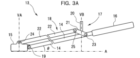
- FIG. 11 is an explanatory side view showing a curette according to a third embodiment of the present invention.
- 3B is an explanatory side view of the curette of the third embodiment, in which the angle of the head portion relative to the shaft portion is different from that in FIG. 3A .
- FIG. 13 is an explanatory plan view of a curette according to a third embodiment.
- FIG. 4 is an explanatory diagram showing an example of a fixing mechanism.
- FIG. 13 is an explanatory side view showing a curette according to a fourth embodiment of the present invention.
- FIG. 13 is an enlarged plan view of a head portion constituting a curette according to a fourth embodiment, as viewed from the line of sight of an arrow D.
- FIG. 13 is an explanatory diagram showing a state in which the curette of the fourth embodiment is used.
- a curette 1 of the first embodiment includes a shaft portion 2, a head portion 3, and a grip portion 4.
- the grip portion 4 is provided with a posture recognition portion 5, which is the gist of the present invention.
- the shaft portion 2 is formed in a straight rod shape and is made of a material that does not bend or bends very little.
- the head portion 3 is formed in a ring shape and is provided at the tip of the shaft portion 2.
- the head portion 3 is provided in one direction at an angle ⁇ relative to the shaft portion 2. This makes it easier to place the head portion 3 on the affected area and perform treatments such as trimming and smoothing the cartilage defect.
- the angle ⁇ of the head portion 3 is set to a value suitable for performing the treatment by placing the plane on which the ring of the head portion 3 resides against the approximate plane of the affected area and moving it in parallel.
- a value suitable for performing the treatment by placing the plane on which the ring of the head portion 3 resides against the approximate plane of the affected area and moving it in parallel.
- multiple curettes with different angles ⁇ of the head portion 3 are prepared depending on the condition and position of the affected area, and one of the curettes is selectively used during the treatment.
- the grip section 4 is provided at the rear end of the shaft section 2 and is made larger in diameter than the shaft section 2, making it easier to operate.
- the vertical direction of the affected surface i.e., the orientation of the affected surface
- the vertical direction of the affected surface can be easily recognized simply by placing the head portion 3 against the affected surface and visually checking the inclined surface 6.
- a curette 7 of the second embodiment includes a shaft portion 8, a head portion 9, and a grip portion 10.
- the shaft portion 8 is provided with a posture recognition portion 11, which is the gist of the present invention.
- the shaft portion 8 is formed in a straight rod shape and is made of a material that does not bend or bends very little.
- the head portion 9 is formed in a ring shape and is provided at the tip of the shaft portion 8.
- the head portion 9 is provided in one direction at an angle ⁇ relative to the shaft portion 8. This makes it easier to place the head portion 9 on the affected area and perform treatments such as trimming and smoothing the cartilage defect.
- the angle ⁇ of the head portion 9 is set to a value suitable for performing the treatment by placing the plane to which the ring of the head portion 9 belongs against the approximate plane of the affected area and moving it in parallel.
- a value suitable for performing the treatment by placing the plane to which the ring of the head portion 9 belongs against the approximate plane of the affected area and moving it in parallel.
- multiple curettes with different angles ⁇ of the head portion 9 are prepared and selectively used depending on the condition and position of the affected area.
- the grip portion 10 is provided at the rear end of the shaft portion 8 and is formed with a larger diameter than the shaft portion 8, making it easier to operate.
- the posture recognition unit 11 in the second embodiment is configured with a pin-shaped pointer 12 provided on the shaft portion 8.
- the pointer 12 intersects with the shaft portion 8 and extends to one side of the shaft portion 8.
- the side of the shaft portion 8 on which the pointer 12 is provided coincides with the side on which the head portion 9 protrudes relative to the shaft portion 8.
- the pointer 12 is installed on the shaft 8 so that the vertical direction VB of the imaginary plane B is parallel to the vertical direction VA of the plane (plane A) that contacts the plane to which the ring of the head 9 belongs.
- the orientation of the affected surface can be easily recognized simply by placing the head portion 9 against the affected surface and visually checking the pointer portion 12.
- the curette 13 of the third embodiment includes a shaft portion 14, a head portion 15, and a grip portion 16, and further includes a posture recognition portion 17 and a link mechanism 18, which are the gist of the present invention, on the shaft portion 14.
- the head portion 15 is connected to the tip of the shaft portion 14 via a first pivot shaft 19 so that it can swing freely. This allows the angle ⁇ of the head portion 15 relative to the shaft portion 14 to be changed.
- the grip portion 16 is provided at the rear end of the shaft portion 14 and is formed with a larger diameter than the shaft portion 14, making it easier to operate.
- the posture recognition unit 17 in the third embodiment is composed of a pin-shaped pointer 20, which is supported by a support member 21 that constitutes the link mechanism 18.
- the link mechanism 18 includes a support member 21 and a link member 22 that extends parallel to the shaft portion 14.
- the support member 21 is provided near the grip portion 16 of the shaft portion 14 so as to be able to swing freely via a second swing shaft 23, and the pointer portion 20 is provided with its base end fixed to the support member 21.
- the link member 22 has a tip connected to the head portion 15 via a rotatable first connecting shaft 24, and a rear end connected to the support member 21 via a second connecting shaft 25.
- the pointer 20 supported by the support member 21 is arranged so as to be parallel to the vertical direction VA of the plane (plane A) on which the plane of the head 15 is placed, as shown in Figures 3A and 3B.
- the imaginary extension line VB of the pointer 20 becomes parallel to the vertical direction VA of plane A.
- the vertical direction of the plane of the head 15 is reflected in the direction of the pointer 20.
- the angle ⁇ of the head portion 15 relative to the shaft portion 14 can be set to any desired angle, eliminating the need to prepare multiple head portions with different angles for surgery. Furthermore, since the direction of the pointer portion 20 corresponds to the vertical direction of the plane of the head portion 15, the vertical direction of the plane of the head portion 15 can be accurately recognized by looking at the pointer portion 20, regardless of the angle ⁇ of the head portion 15 relative to the shaft portion 14.
- a ratchet mechanism 26 shown in FIG. 5 can be provided as a fixing mechanism that fixes the angle ⁇ of the head portion 15 relative to the shaft portion 14 at a desired angle.
- the head portion 15 can be easily fixed and released.
- the ratchet mechanism 26 is composed of a locking member 27 provided on the shaft portion 14 and locking teeth 28 provided on the support member 21.
- the locking member 27 has a body portion 29 having elasticity, such as a spring material, one end of which is fixed to the shaft portion 14, and a claw portion 30 protruding from the other end of the body portion 29.
- the locking teeth 28 are provided on the opposite side of the second connecting shaft 25 via the second oscillating shaft 23 of the support member 21, and the claw portion 30 of the locking member 27 resiliently locks.
- a curette 30 of the fourth embodiment includes a shaft portion 31 extending a predetermined length, a head portion 33 provided at a tip portion 31a in the extending direction of the shaft portion 31, and a grip portion 35 provided at a base end portion in the extending direction of the shaft portion 31.
- a posture recognition portion 37 which is the gist of the present invention, is provided on the outer periphery of the tip portion 35a of the grip portion 35.
- the head portion 33 is generally cylindrical and has a predetermined axial length.
- a surface 40 is provided on the outer peripheral edge of the head portion 33 on the axial tip side, and a surface 41 is also provided on the outer peripheral edge of the head portion 33 on the axial base end side, with both surfaces 40, 41 being parallel to each other.
- Surface 40 on the tip side of the head portion 33 forms the "surface" in this invention.
- an inner blade 42 capable of trimming, for example, cartilage defects is provided on the radially inner side of the head portion 33.
- the inner blade 42 may be provided on both axial ends of the head portion 33, i.e., on surfaces 40 and 41, or on one end, i.e., on surface 40 or surface 41. However, in the present invention, it is preferable that the inner blade 42 is provided only on surface 40.
- the cylindrical head portion 33 is bent at a predetermined angle relative to the tip portion 31a of the shaft portion 31.
- the head portion 33 is bent relative to the tip portion 31a of the shaft portion 31 so that the inclination angle of the axis C2 of the head portion 33 relative to the axis C1 of the shaft portion 31 is ⁇ 1.
- the direction perpendicular to the plane A to which the surface 40 of the head portion 33 belongs is the same as the direction along the axis C2 of the head portion 33.
- the head portion 33 is cylindrical and extends in the perpendicular direction to the plane A to which the surface 40 belongs.
- the posture recognition unit 37 has a bent protrusion shape consisting of a base 38 that is disposed perpendicular to the axis C1 of the shaft 31 and is connected to the tip 35a of the grip 35, and a bent portion 39 that is bent at a predetermined angle relative to the base 38 and extends a predetermined length.
- the bent portion 39 of the posture recognition unit 37 is bent so that its axis C3 is at an inclination angle ⁇ 2 relative to the axis C1 of the shaft 31.
- the inclination angle ⁇ 2 of the bent portion 39 of the posture recognition unit 37 relative to the axis C1 of the shaft portion 31 is the same as the inclination angle ⁇ 1 of the head portion 33 relative to the axis C1 of the shaft portion 31.
- the extension direction (direction along axis C3) of bent portion 39 of posture recognition unit 37 is perpendicular to plane A to which surface 40 of head portion 33 belongs, that is, the same as the direction along axis C2 of head portion 33.
- the vertical direction of the surface 40 of the head unit 33 and the extension direction of the bent portion 39 of the posture recognition unit 37 are the same, so that the orientation of the affected surface can be easily recognized by simply pressing the cylindrical surface 40 of the head unit 33 against the affected surface, such as a cartilage defect, as shown in FIG. 7, and visually checking the bent portion 39 of the posture recognition unit 37.
- the inclination angle ⁇ 1 of the head portion 33 is set to a value suitable for performing the treatment by placing the surface 40 of the head portion 33 on the approximate plane of the affected area and moving it in parallel. For example, multiple curettes with different angles ⁇ 1 of the head portion 33 are prepared and used selectively depending on the condition and position of the affected area.
- the surface 40 provided on the head portion 33 is located at a position that protrudes from the tip portion 31a of the shaft portion 31 toward the axial tip side of the head portion 33. Therefore, according to the head portion 33 of the fourth embodiment, the surface 40 can be used to efficiently perform treatments such as trimming and smoothing the cartilage defect on the affected surface.
- the head portion is formed in a ring shape, but the shape of the head portion is not limited to this.
- Another aspect of the present invention is, for example, a surgical tool having a head portion of various shapes at the tip, such as a spoon shape or a needle shape, although not shown.
- the configuration of the present invention can be applied to a surgical tool whose tip is inserted into the affected area and the tip cannot be seen during use.
- the head portion at the tip of such a surgical tool may or may not have a surface, and examples of such a surgical tool include a curette, a microfracture pick, endoscopic forceps, a surgical hook, and a cannula.
Landscapes
- Health & Medical Sciences (AREA)
- Surgery (AREA)
- Life Sciences & Earth Sciences (AREA)
- Biomedical Technology (AREA)
- Nuclear Medicine, Radiotherapy & Molecular Imaging (AREA)
- Engineering & Computer Science (AREA)
- Orthopedic Medicine & Surgery (AREA)
- Heart & Thoracic Surgery (AREA)
- Medical Informatics (AREA)
- Molecular Biology (AREA)
- Animal Behavior & Ethology (AREA)
- General Health & Medical Sciences (AREA)
- Public Health (AREA)
- Veterinary Medicine (AREA)
- Surgical Instruments (AREA)
Priority Applications (1)
| Application Number | Priority Date | Filing Date | Title |
|---|---|---|---|
| JP2025532796A JPWO2025013885A1 (https=) | 2023-07-11 | 2024-07-10 |
Applications Claiming Priority (2)
| Application Number | Priority Date | Filing Date | Title |
|---|---|---|---|
| JP2023-113525 | 2023-07-11 | ||
| JP2023113525 | 2023-07-11 |
Publications (1)
| Publication Number | Publication Date |
|---|---|
| WO2025013885A1 true WO2025013885A1 (ja) | 2025-01-16 |
Family
ID=94215905
Family Applications (1)
| Application Number | Title | Priority Date | Filing Date |
|---|---|---|---|
| PCT/JP2024/024864 Pending WO2025013885A1 (ja) | 2023-07-11 | 2024-07-10 | 姿勢確認装置付きキュレット |
Country Status (2)
| Country | Link |
|---|---|
| JP (1) | JPWO2025013885A1 (https=) |
| WO (1) | WO2025013885A1 (https=) |
Citations (2)
| Publication number | Priority date | Publication date | Assignee | Title |
|---|---|---|---|---|
| JP2021171224A (ja) * | 2020-04-22 | 2021-11-01 | 学校法人自治医科大学 | 外科手術器具用グリップ |
| WO2022191259A1 (ja) * | 2021-03-11 | 2022-09-15 | 持田製薬株式会社 | 姿勢確認装置及び姿勢調節方法 |
-
2024
- 2024-07-10 JP JP2025532796A patent/JPWO2025013885A1/ja active Pending
- 2024-07-10 WO PCT/JP2024/024864 patent/WO2025013885A1/ja active Pending
Patent Citations (2)
| Publication number | Priority date | Publication date | Assignee | Title |
|---|---|---|---|---|
| JP2021171224A (ja) * | 2020-04-22 | 2021-11-01 | 学校法人自治医科大学 | 外科手術器具用グリップ |
| WO2022191259A1 (ja) * | 2021-03-11 | 2022-09-15 | 持田製薬株式会社 | 姿勢確認装置及び姿勢調節方法 |
Also Published As
| Publication number | Publication date |
|---|---|
| JPWO2025013885A1 (https=) | 2025-01-16 |
Similar Documents
| Publication | Publication Date | Title |
|---|---|---|
| JP6932727B2 (ja) | 骨を切断するための医療装置 | |
| US9913636B2 (en) | Multiple portal guide | |
| EP2789302B1 (en) | Orthopedic external fixation device | |
| US9826992B2 (en) | Multiple portal guide | |
| US8231630B2 (en) | Humeral rotating burr guide | |
| US7008430B2 (en) | Adjustable reamer with tip tracker linkage | |
| KR101651627B1 (ko) | 제어자의 모션을 로봇 매니퓰레이터로부터 부착된 기구로 전달하기 위한 커플러 | |
| US8323291B2 (en) | Partial aiming device for targeting an arthroscopic operation site for a medical intervention | |
| JP5571086B2 (ja) | 角度計 | |
| WO2019193775A1 (ja) | アーム装置 | |
| KR20230079492A (ko) | 구강 및 상악안면 수술들을 수행하기 위한 방법들 및 관련 시스템 | |
| WO2010029962A1 (ja) | ナビゲーション手術用アンテナ保持器 | |
| US20230107823A1 (en) | Surgical instrument | |
| JP6243004B2 (ja) | 寛骨臼補綴を内移植するための手術器具類の組合せ | |
| JP2024522823A5 (https=) | ||
| WO2025013885A1 (ja) | 姿勢確認装置付きキュレット | |
| WO2022191259A1 (ja) | 姿勢確認装置及び姿勢調節方法 | |
| JP3778572B2 (ja) | 柔軟性に富む手術用器具 | |
| TWI740673B (zh) | 手術器械支持器 | |
| JP7313630B2 (ja) | 内視鏡装置 | |
| JP7385195B2 (ja) | 内視鏡装置 | |
| JP2008526405A (ja) | 外科手術器具の位置及び向きを表示する方法及び該方法を実施するための装置 | |
| JP5952953B1 (ja) | 処置具用屈曲機構及び処置具 | |
| EP4483832A1 (en) | Surgical system for ear, nose, throat surgeries | |
| JP2007319510A (ja) | 指標器具及び外科手術器具システム |
Legal Events
| Date | Code | Title | Description |
|---|---|---|---|
| 121 | Ep: the epo has been informed by wipo that ep was designated in this application |
Ref document number: 24839775 Country of ref document: EP Kind code of ref document: A1 |
|
| ENP | Entry into the national phase |
Ref document number: 2025532796 Country of ref document: JP Kind code of ref document: A |
|
| WWE | Wipo information: entry into national phase |
Ref document number: 2025532796 Country of ref document: JP |
|
| NENP | Non-entry into the national phase |
Ref country code: DE |