WO2025013628A1 - コネクタ - Google Patents
コネクタ Download PDFInfo
- Publication number
- WO2025013628A1 WO2025013628A1 PCT/JP2024/023164 JP2024023164W WO2025013628A1 WO 2025013628 A1 WO2025013628 A1 WO 2025013628A1 JP 2024023164 W JP2024023164 W JP 2024023164W WO 2025013628 A1 WO2025013628 A1 WO 2025013628A1
- Authority
- WO
- WIPO (PCT)
- Prior art keywords
- electrical contact
- inclined surface
- contact member
- flexible conductor
- opposite direction
- Prior art date
- Legal status (The legal status is an assumption and is not a legal conclusion. Google has not performed a legal analysis and makes no representation as to the accuracy of the status listed.)
- Pending
Links
Images


Classifications
-
- H—ELECTRICITY
- H01—ELECTRIC ELEMENTS
- H01R—ELECTRICALLY-CONDUCTIVE CONNECTIONS; STRUCTURAL ASSOCIATIONS OF A PLURALITY OF MUTUALLY-INSULATED ELECTRICAL CONNECTING ELEMENTS; COUPLING DEVICES; CURRENT COLLECTORS
- H01R13/00—Details of coupling devices of the kinds covered by groups H01R12/70 or H01R24/00 - H01R33/00
- H01R13/02—Contact members
- H01R13/15—Pins, blades or sockets having separate spring member for producing or increasing contact pressure
-
- H—ELECTRICITY
- H01—ELECTRIC ELEMENTS
- H01R—ELECTRICALLY-CONDUCTIVE CONNECTIONS; STRUCTURAL ASSOCIATIONS OF A PLURALITY OF MUTUALLY-INSULATED ELECTRICAL CONNECTING ELEMENTS; COUPLING DEVICES; CURRENT COLLECTORS
- H01R13/00—Details of coupling devices of the kinds covered by groups H01R12/70 or H01R24/00 - H01R33/00
- H01R13/02—Contact members
- H01R13/22—Contacts for co-operating by abutting
- H01R13/24—Contacts for co-operating by abutting resilient; resiliently-mounted
Definitions
- This disclosure relates to connectors.
- vehicles are equipped with connectors that include a terminal module and a housing that houses the terminal module.
- the terminal module has an electrical contact member against which a mating terminal of a mating connector is butted, a braided wire joined to the electrical contact member, and an external connection member joined to the braided wire.
- the two contacts are caused to slide against each other to remove foreign matter between the contacts (see, for example, Patent Document 1).
- An object of the present disclosure is to provide a connector that can be miniaturized.
- the connector of the present disclosure is a connector that is electrically connected to a mating connector having a mating terminal, and includes an electrical contact member to which the mating terminal is connected along a first direction, a holding member that holds the electrical contact member movably between a first position and a second position, an external connection member that is disposed outside the holding member, and a flexible conductor that electrically connects the electrical contact member and the external connection member, the second position being a position different from the first position in the first direction and a position different from the first position in a second direction that intersects with the first direction, the flexible conductor extending along the second direction between the electrical contact member and the external connection member, the flexible conductor being more flexible than the electrical contact member, and the flexible conductor being capable of flexural deformation in response to the movement of the electrical contact member.
- the connector disclosed herein has the advantage of being compact.
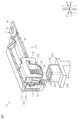
- FIG. 1 is a perspective view showing a connector according to an embodiment.
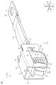
- FIG. 2 is a cross-sectional perspective view showing a connector according to an embodiment.
- FIG. 3 is an exploded perspective view showing a connector according to an embodiment.
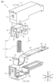
- FIG. 4 is a perspective view showing a terminal module according to an embodiment.
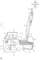
- FIG. 5 is an exploded perspective view showing a terminal module according to an embodiment.
- FIG. 6 is an exploded perspective view showing a terminal module according to one embodiment.
- FIG. 7 is a plan view showing a connector according to an embodiment.
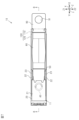
- FIG. 8 is a cross-sectional view (cross-sectional view taken along line 8-8 in FIG. 7) showing the connector of one embodiment.
- FIG. 9 is a cross-sectional view showing a connector according to an embodiment.
- the connector of the present disclosure is a connector electrically connected to a mating connector having a mating terminal, and comprises: an electrical contact member to which the mating terminal is connected along a first direction; a holding member that holds the electrical contact member movably between a first position and a second position; an external connection member that is arranged on the outside of the holding member; and a flexible conductor that electrically connects the electrical contact member and the external connection member, wherein the second position is a position different from the first position in the first direction and is a position different from the first position in a second direction that intersects the first direction, the flexible conductor extends along the second direction between the electrical contact member and the external connection member, the flexible conductor is more flexible than the electrical contact member, and the flexible conductor is capable of flexural deformation in response to movement of the electrical contact member.
- the electrical contact member and the external connection member are connected by a flexible conductor that is more flexible than the electrical contact member.
- This flexible conductor is flexibly deformed in response to the movement of the electrical contact member. Therefore, when the electrical contact member moves between the first position and the second position, that is, when the electrical contact member and the external connection member move relatively, even if the external connection member is fixed, the flexible conductor is prevented from flexibly deforming and hindering the movement of the electrical contact member.
- the flexible conductor is formed to extend along a second direction intersecting with the first direction, which is the movement direction of the mating terminal relative to the electrical contact member.
- the size of the connector in the first direction can be made smaller than in the conventional configuration in which the flexible conductor extends along the first direction, which is the movement direction of the mating terminal relative to the electrical contact member.
- the connector when the connector is mounted on the device to be mounted, the connector is mounted so as to protrude from the outer surface of the housing of the device to be mounted in the first opposite direction, which is the opposite direction to the first direction. Therefore, if the size of the connector in the first direction can be made smaller, the entire device to be mounted on which the connector is mounted can be made smaller.
- the end of the flexible conductor in the second direction may be connected to an end of the electrical contact member in a second opposite direction that is opposite to the second direction, and the end of the flexible conductor in the second opposite direction may be connected to an end of the external connection member in the second direction, and the external connection member may extend from the end of the flexible conductor in the second opposite direction along the second opposite direction.
- a flexible conductor is formed so as to extend along the second opposite direction from the end of the electrical contact member in the second opposite direction, and an external connection member is connected to the end of the flexible conductor in the second opposite direction.
- the external connection member is then formed so as to extend along the second opposite direction from the end of the flexible conductor in the second opposite direction. Therefore, the size of the connector in the first direction can be made smaller than in the conventional configuration in which the external connection member extends along the first direction, which is the movement direction of the mating terminal relative to the electrical contact member.
- the flexible conductor may be a separate part from the electrical contact member and the external connection member, and the flexible conductor may be a braided wire made of multiple metal wires woven together.
- the electrical contact member and the external connection member are connected by the braided wire, which is a separate component from the electrical contact member and the external connection member.
- the braided wire which is a flexible conductor, flexes and deforms in response to the movement of the electrical contact member. Therefore, when the electrical contact member moves between the first position and the second position, even if the external connection member is fixed, it is possible to prevent the braided wire from flexing and deforming to interfere with the movement of the electrical contact member.
- the holding member may have a first inclined surface inclined with respect to the first direction and inclined with respect to the second direction
- the electrical contact member may have a second inclined surface extending parallel to the first inclined surface
- the electrical contact member may be movable from the first position to the second position while sliding on the first inclined surface with the second inclined surface in contact with the first inclined surface when the mating terminal is connected along the first direction.
- the second inclined surface slides on the first inclined surface while contacting the first inclined surface of the holding member, thereby guiding the electrical contact member from the first position to the second position along the direction in which the first inclined surface extends.
- the contact area of the guide portion when the electrical contact member moves that is, the contact area between the first inclined surface and the second inclined surface, can be made larger. This makes it possible to reduce the surface pressure applied from the second inclined surface to the first inclined surface. Therefore, it is possible to reduce the amount of wear during sliding on the first inclined surface and the second inclined surface. As a result, it is possible to improve the durability of the electrical contact member and the holding member. In turn, it is possible to improve the durability of the connector.
- the connector may further include an elastic member sandwiched between the electrical contact member and an inner surface of the retaining member facing a first opposite direction that is the opposite direction to the first direction, the retaining member having an opening that opens in the first opposite direction and through which the mating terminal enters along the first direction, the electrical contact member is biased toward the opening by the elastic member, and the electrical contact member may be movable from the first position to the second position against the biasing force of the elastic member when the mating terminal is connected along the first direction.
- the biasing force of the elastic member allows the electrical contact member to be brought into favorable contact with the mating terminal. This improves the reliability of the electrical connection between the electrical contact member and the mating terminal.
- the holding member has a third inclined surface extending parallel to the first inclined surface
- the electrical contact member has a fourth inclined surface extending parallel to the third inclined surface
- the third inclined surface is spaced apart from the first inclined surface in the second direction
- the fourth inclined surface is spaced apart from the second inclined surface in the second direction and faces the third inclined surface in the second direction
- the electrical contact member may be movable from the second position to the first position while sliding on the third inclined surface with the fourth inclined surface in contact with the third inclined surface when the electrical contact member is disconnected from the mating terminal.
- the fourth inclined surface slides on the third inclined surface while contacting the third inclined surface of the holding member, thereby guiding the electrical contact member from the second position to the first position along the direction in which the third inclined surface extends.
- the inclined surfaces of the third inclined surface and the fourth inclined surface extending parallel to the third inclined surface come into contact with each other. Therefore, compared to when an inclined surface and a vertical surface come into contact with each other, the contact area of the guide portion when the electrical contact member moves, that is, the contact area between the third inclined surface and the fourth inclined surface, can be made larger. This makes it possible to reduce the surface pressure applied from the fourth inclined surface to the third inclined surface. Therefore, the amount of wear when sliding on the third inclined surface and the fourth inclined surface can be reduced.
- the electrical contact member has a bottom wall that contacts the mating terminal, the second inclined surface protruding from a first edge of the bottom wall, and the fourth inclined surface protruding from a second edge of the bottom wall, and the second inclined surface may be formed integrally with the bottom wall, and the fourth inclined surface may be formed integrally with the bottom wall.
- the electrical contact member has a structure in which the bottom wall, the second inclined surface, and the fourth inclined surface are integrally formed. This simplifies the structure of the electrical contact member compared to when the bottom wall, the second inclined surface, and the fourth inclined surface are each formed as separate parts.
- the electrical contact member may have a connection piece portion extending from an end of the fourth inclined surface in the first direction along a second opposite direction that is the opposite direction to the second direction, and the end of the flexible conductor in the second direction may be connected to the end of the connection piece portion in the second opposite direction.
- the flexible conductor is formed so as to extend along the second opposite direction from the end of the connection piece portion in the second opposite direction that extends along the second opposite direction.
- the size of the connector in the first direction can be suitably reduced.
- the retaining member is a metal case having a ceiling wall, a pair of side walls protruding from both side edges of the ceiling wall, the first inclined surface provided between the pair of side walls, and an opening through which the mating terminal enters along the first direction, the pair of side walls facing each other in a third direction intersecting both the first direction and the second direction, and the electrical contact member may be disposed between the pair of side walls.
- the electrical contact member is held inside the box portion of the metal case, which is composed of a ceiling wall and a pair of side walls.
- a first inclined surface is provided between the pair of side walls. Therefore, the first inclined surface and the second inclined surface can be brought into contact with each other inside the box portion of the case.
- the device may further include a resin housing that houses the electrical contact member, the holding member, and the soft conductor therein, the housing having a first divided body and a second divided body that is formed so as to be combineable with the first divided body, and the housing may be formed into a cylindrical shape that houses the electrical contact member, the holding member, and the soft conductor therein by combining the first divided body and the second divided body.
- the housing is formed into a cylindrical shape by the first and second divisions, and houses the electrical contact member, the holding member, and the flexible conductor inside.
- the housing is cylindrical, because the housing is divided into the first and second divisions, the housing can be retrofitted to the electrical contact member, the holding member, and the flexible conductor. This improves the ease of assembling the housing to the electrical contact member, the holding member, and the flexible conductor.
- the "cylindrical” used in the description of this specification includes not only those in which a peripheral wall is formed continuously around the entire circumference, but also those in which a plurality of parts are combined to form a cylindrical shape, and those having a notch in a part of the circumference such as a C-shape or U-shape.
- the shape of the "cylindrical” includes, but is not limited to, a circle, an ellipse, and a polygon with sharp or rounded corners.
- “opposite” refers to surfaces or members being in front of each other, including not only the case where they are completely in front of each other, but also the case where they are partially in front of each other.
- the connector 10 includes one or more terminal modules 11 and a housing 100 that accommodates the terminal modules 11.
- the terminal modules 11 include electrical contact members 50.
- the connector 10 electrically connects, for example, electrical devices for a vehicle to each other. Examples of the electrical devices for a vehicle include a battery pack, an inverter, and a motor.
- Each drawing shows an X-axis, a Y-axis, and a Z-axis that are mutually orthogonal.
- Each drawing shows a first direction X1, which is a direction in the X-axis direction along the X-axis, and a first opposite direction X2, which is the opposite direction of the first direction X1.
- Each drawing shows a second direction Y1, which is a direction in the Y-axis direction along the Y-axis, and a second opposite direction Y2, which is the opposite direction of the second direction Y1.
- Each drawing shows a third direction Z1, which is a direction in the Z-axis direction along the Z-axis, and a third opposite direction Z2, which is the opposite direction of the third direction Z1.
- the directions in each drawing do not necessarily represent the posture of the connector 10 and the terminal module 11 when in use.
- FIG. 2 is an oblique view showing only the housing 100 of the connector 10 in cross section.
- the connector 10 is electrically connected to the mating connector 200.
- the mating connector 200 is connected to the connector 10, for example, along the first direction X1.
- the mating terminal 201 of the mating connector 200 is inserted into the housing 100 along the first direction X1.
- the mating terminal 201 is abutted against the electrical contact member 50 of the terminal module 11 along the first direction X1, so that the mating terminal 201 and the electrical contact member 50 are electrically connected to each other.
- the mating connector 200 includes, for example, one or more mating terminals 201 and a mating housing 202 that holds the mating terminals 201.
- the mating terminals 201 are made of metal.
- the mating housing 202 is made of synthetic resin.
- the mating terminal 201 is formed, for example, in an L-shape by bending a metal plate extending in the Y-axis direction at a right angle in the first opposite direction X2.
- One or more (two in this embodiment) mating contacts 203 are provided on the end face of the mating terminal 201 in the first direction X1 that faces the electrical contact member 50 of the terminal module 11.
- Each mating contact 203 is formed, for example, so as to protrude in the first direction X1 from the end face of the mating terminal 201 in the first direction X1.
- Each mating contact 203 extends, for example, in the Z-axis direction.
- the two mating contacts 203 are provided side by side along the Y-axis direction.
- Each mating terminal 201 is integrally formed with the mating housing 202 by, for example, insert molding.
- the terminal module 11 includes a case 20, a coil spring 40, and an electrical contact member 50.
- the terminal module 11 includes a flexible conductor 80 electrically connected to the electrical contact member 50, and an external connection member 90 electrically connected to the flexible conductor 80.
- the case 20, the coil spring 40, the electrical contact member 50, the flexible conductor 80, and the external connection member 90 are each separate components.
- the case 20 holds the electrical contact member 50.
- the case 20 is formed in a box shape as a whole.
- the case 20 is formed in a box shape capable of accommodating the coil spring 40 and the electrical contact member 50 therein.
- the case 20 is formed, for example, by bending and combining metal plates.
- the case 20 of this embodiment is formed by bending a single metal plate.
- the case 20 is made of, for example, metal.
- the case 20 can be made of, for example, copper, copper alloy, aluminum, aluminum alloy, or stainless steel (SUS).
- the case 20 has a ceiling wall 21, a pair of side walls 22, one or more (two in this embodiment) guide portions 30, and one or more (two in this embodiment) guide portions 35.
- the case 20 has, for example, an engagement piece 38.
- the case 20 has an opening 20X that opens in the first opposite direction X2 and through which the mating terminal 201 (see Figure 2) can enter.
- the ceiling wall 21 is formed in a flat plate shape.
- the ceiling wall 21 has a thickness direction extending along the X-axis.
- the ceiling wall 21 has a length direction extending along the Y-axis.
- the ceiling wall 21 has a width direction extending along the Z-axis.
- the pair of side walls 22 protrude from both side edges of the ceiling wall 21.
- Each of the pair of side walls 22 protrudes from each end of the width direction (here, the Z-axis direction) of the ceiling wall 21 toward the first opposite direction X2.
- the pair of side walls 22 face each other in the width direction of the ceiling wall 21.
- Each side wall 22 is formed in a flat plate shape.
- Each side wall 22 extends linearly along the X-axis direction.
- Each side wall 22 extends along the length direction of the ceiling wall 21 (here, the Y-axis direction) over the entire length of the length direction of the ceiling wall 21.
- Each side wall 22 is formed, for example, by bending at a right angle from each end of the width direction of the ceiling wall 21 toward the first opposite direction X2.
- each side wall 22 has an extension 23 that extends in the second opposite direction Y2, for example, further than the second opposite direction Y2 of the ceiling wall 21.
- Each extension 23 is formed to protrude in the second opposite direction Y2 further than the second opposite direction Y2 of the ceiling wall 21.
- the ceiling wall 21 is not provided between a pair of extensions 23. Note that in FIG. 7, the first division 110 of the housing 100 is drawn in perspective, and the outline of the first division 110 is shown by a two-dot chain line.
- each side wall 22 has, for example, a notch 24.
- Each notch 24 is formed such that the side wall 22 is cut out from the end face of the side wall 22 in the first opposite direction X2 toward the first direction X1.
- Each notch 24 opens in both the third direction Z1 and the third opposite direction Z2, and also opens in the first opposite direction X2.
- Each notch 24 is provided at a midpoint in the Y-axis direction of the side wall 22.
- Each notch 24 is also formed in, for example, a part of the extension portion 23.
- the box portion of the case 20 which is formed by the ceiling wall 21 and the pair of side walls 22, is open in both the second direction Y1 and the second opposite direction Y2, and is also open in the first opposite direction X2.
- the box portion of the case 20 has an opening 20X that opens in the first opposite direction X2.
- the two guide portions 30 are provided between a pair of side walls 22.
- the two guide portions 30 are provided apart from each other in the Z-axis direction.
- Each guide portion 30 is provided, for example, at a middle position of the side wall 22 in the length direction of the side wall 22 (here, the Y-axis direction).
- Each guide portion 30 is provided, for example, at an end edge of the second direction Y1 of the notch portion 24.
- Each guide portion 30 is formed, for example, by bending a part of the end portion of the side wall 22 in the first opposite direction X2 toward the paired side wall 22, i.e., the other side wall 22.
- each guide portion 30 is formed by bending a part of the side wall 22 by 90° or more. Therefore, a curved surface is formed at the connection portion between each side wall 22 and each guide portion 30.
- each guide portion 30 has an inclined surface 31.
- Each inclined surface 31 faces, for example, in the second opposite direction Y2.
- Each inclined surface 31 is inclined with respect to the first direction X1 and is also inclined with respect to the second direction Y1.
- each inclined surface 31 is inclined toward the second opposite direction Y2, for example, from the end of the guide portion 30 in the first opposite direction X2 toward the end of the guide portion 30 in the first direction X1.
- the end of the inclined surface 31 in the first direction X1 is provided at a position shifted in the second opposite direction Y2 from the end of the inclined surface 31 in the first opposite direction X2, that is, at a position shifted in a direction shifted laterally with respect to the entry direction of the mating terminal 201 (here, the first direction X1).
- Each inclined surface 31 extends, for example, at a constant inclination angle. That is, each inclined surface 31 extends along the oblique direction S1 that is inclined with respect to both the first direction X1 and the second direction Y1. As shown in FIG. 6, each inclined surface 31 is formed on a plane that extends in the third direction Z1 and also in the oblique direction S1.
- the two guide parts 35 are provided between a pair of side walls 22.
- the two guide parts 35 are provided apart from each other in the Z-axis direction.
- the two guide parts 35 are provided so as to face the two guide parts 30 in the Y-axis direction.
- Each guide part 35 is provided, for example, at a middle position of the side wall 22 in the length direction of the side wall 22 (here, the Y-axis direction).
- Each guide part 35 is provided, for example, at an end edge of the second opposite direction Y2 of the notch 24.
- Each guide part 35 is formed, for example, by bending a part of the end of the side wall 22 in the first opposite direction X2 toward the paired side wall 22, that is, the other side wall 22.
- each guide part 35 is formed by bending a part of the side wall 22 by 90° or more. Therefore, a curved surface is formed at the connection part between each side wall 22 and each guide part 35.
- each guide portion 35 has an inclined surface 36.
- Each inclined surface 36 faces, for example, in the second direction Y1.
- Each inclined surface 36 is separated from each inclined surface 31 in the Y-axis direction.
- Each inclined surface 36 faces each inclined surface 31 in the Y-axis direction.
- Each inclined surface 36 is inclined with respect to the first direction X1 and is inclined with respect to the second direction Y1.
- Each inclined surface 36 extends, for example, parallel to each inclined surface 31. That is, each inclined surface 36 extends at the same inclination angle as each inclined surface 31. In other words, each inclined surface 36 extends along the diagonal direction S1.
- Each inclined surface 36 is formed on a plane that extends in the third direction Z1 and also in the diagonal direction S1.
- a portion of the side wall 22 is bent to form the guide portion 30, and a portion of the side wall 22 is bent to form the guide portion 35. This forms a notch 24 in the side wall 22.
- the engagement piece 38 protrudes from the end of the ceiling wall 21 in the second opposite direction Y2 toward the first opposite direction X2.
- the engagement piece 38 is formed, for example, by bending at a right angle from the end of the ceiling wall 21 in the second opposite direction Y2 toward the first opposite direction X2.
- the engagement piece 38 is provided, for example, only at the middle position in the width direction of the ceiling wall 21.
- the engagement piece 38 is provided so as to face the coil spring 40 in the Y-axis direction.
- the engagement piece 38 is provided so as to be able to engage with the coil spring 40.
- the coil spring 40 is an elastic member sandwiched between the ceiling wall 21 of the case 20 and the electrical contact member 50.
- the coil spring 40 is formed by winding a metal wire into a coil shape.
- the coil spring 40 is housed inside the case 20 in a state where it is compressed in the X-axis direction by the ceiling wall 21 of the case 20 and the bottom wall 51 of the electrical contact member 50.
- the coil spring 40 biases the electrical contact member 50 toward the opening 20X of the case 20. That is, the coil spring 40 biases the electrical contact member 50 toward the first opposite direction X2.
- the electric contact member 50 is accommodated in the case 20.
- the electric contact member 50 is provided between a pair of side walls 22.
- the electric contact member 50 is movable between a first position (see Fig. 8) and a second position (see Fig. 9). That is, the electric contact member 50 is held by the case 20 so as to be movable between the first position and the second position.
- the first position is a position before the mating terminal 201 enters the inside of the housing 100, and is a position in a state in which the electric contact member 50 is biased toward the opening 20X by the biasing force of the coil spring 40.
- Fig. 8 the electric contact member 50 is accommodated in the case 20.
- the electric contact member 50 is provided between a pair of side walls 22.
- the electric contact member 50 is movable between a first position (see Fig. 8) and a second position (see Fig. 9). That is, the electric contact member 50 is held by the case 20 so as to be movable between the first position and the
- the second position is a position in a state in which the electric contact member 50 is pressed toward the first direction X1 by the mating terminal 201.
- the second position is a position different from the first position in the first direction X1 and a position different from the first position in the second direction Y1.
- the second position in this embodiment is a position closer to the ceiling wall 21 than the first position in the first direction X1, and is a position shifted in the second opposite direction Y2 than the first position in the second direction Y1.
- the electrical contact member 50 is formed, for example, by bending or combining metal plate material.
- the electrical contact member 50 of this embodiment is formed by bending a single metal plate material.
- the electrical contact member 50 is made of metal. Examples of materials that can be used for the electrical contact member 50 include copper, copper alloys, aluminum, aluminum alloys, and stainless steel (SUS).
- the electrical contact member 50 has a bottom wall 51 facing the ceiling wall 21 of the case 20, a contact portion 60 protruding from a first edge of the bottom wall 51, and a contact portion 65 protruding from a second edge of the bottom wall 51.
- the electrical contact member 50 has an engagement portion 70 provided at an end of the contact portion 60 in the first direction X1, and a connection piece portion 75 provided at an end of the contact portion 65 in the first direction X1.
- the electrical contact member 50 is a single part in which the bottom wall 51, the contact portions 60, 65, the engagement portion 70, and the connection piece portion 75 are continuously and integrally formed.
- the electrical contact member 50 has, for example, an ⁇ -shaped planar shape as a whole when viewed from the Z-axis direction.
- the plate thickness of the electrical contact member 50 is set according to the current capacity required for the terminal module 11, and has a rigidity that is not deformed by the biasing force of the coil spring 40.
- the bottom wall 51 is formed in a flat plate shape.
- the bottom wall 51 has a thickness direction extending along the X-axis.
- the bottom wall 51 has a length direction extending along the Y-axis.
- the bottom wall 51 has a width direction extending along the Z-axis.
- the end face of the bottom wall 51 in the first opposite direction X2 is a contact surface (contact point) that comes into contact with the mating contact 203 of the mating terminal 201.
- the end face of the bottom wall 51 in the first opposite direction X2 is exposed to the outside of the case 20 through the opening 20X of the case 20.
- the end face of the bottom wall 51 in the first direction X1 faces the end face of the first opposite direction X2 of the ceiling wall 21 in the first direction X1.
- the end face of the bottom wall 51 in the first direction X1 is a spring bearing surface that receives the end of the coil spring 40 in the first opposite direction X2.
- the dimension of the bottom wall 51 along the Y-axis direction is larger than the dimension of the coil spring 40 along the Y-axis direction. As shown in FIG. 5, the dimension of the bottom wall 51 along the Z-axis direction is larger than the dimension of the coil spring 40 along the Z-axis direction.
- the contact portion 60 protrudes in the diagonal direction S1 from a first edge, which is an end portion in the second direction Y1, of the bottom wall 51.
- the contact portion 60 is formed, for example, by bending from the end portion in the second direction Y1 of the bottom wall 51 toward the ceiling wall 21.
- the contact portion 60 is formed by bending from the end portion in the second direction Y1 of the bottom wall 51 by 90° or more.
- the contact portion 60 has an inclined surface 61 facing the two inclined surfaces 31 in the second direction Y1.
- the inclined surface 61 faces the second direction Y1.
- the inclined surface 61 is formed integrally with the bottom wall 51, for example. As shown in FIG. 8, the inclined surface 61 extends parallel to the inclined surface 31. That is, the inclined surface 61 extends at the same inclination angle as the inclined surface 31. In other words, the inclined surface 61 extends along the diagonal direction S1. As shown in FIG. 5, the inclined surface 61 is formed as a plane that extends in the third direction Z1 and also in the diagonal direction S1. The inclined surface 61 extends, for example, along the width direction of the bottom wall 51 (here, the Z-axis direction) over the entire width direction of the bottom wall 51.
- the inclined surface 61 can contact, for example, two inclined surfaces 31.
- the inclined surface 61 can come into surface contact with, for example, two inclined surfaces 31.
- the inclined surface 61 has a size larger than the combined size of the two inclined surfaces 31 when viewed in a plan view from the Y-axis direction.
- the contact portion 65 protrudes in the diagonal direction S1 from a second edge, which is the end of the bottom wall 51 in the second opposite direction Y2.
- the contact portion 65 extends, for example, parallel to the contact portion 60.
- the contact portion 65 is formed, for example, by bending from the end of the bottom wall 51 in the second opposite direction Y2 toward the ceiling wall 21.
- the contact portion 65 is formed by bending from the end of the bottom wall 51 in the second opposite direction Y2 at an angle of 90° or less parallel to the contact portion 60.
- the contact portion 65 has an inclined surface 66 facing the two inclined surfaces 36 in the Y-axis direction.
- the inclined surface 66 faces the second opposite direction Y2.
- the inclined surface 66 is formed integrally with the bottom wall 51, for example.
- the inclined surface 66 extends, for example, parallel to the inclined surface 61.
- the inclined surface 66 extends parallel to the inclined surface 36. That is, the inclined surface 66 extends at the same inclination angle as the inclined surface 36. In other words, the inclined surface 66 extends along the diagonal direction S1.
- the inclined surface 66 is formed as a plane that extends in the third direction Z1 and also in the diagonal direction S1.
- the inclined surface 66 extends, for example, along the width direction of the bottom wall 51 (here, the Z-axis direction) over the entire width direction of the bottom wall 51.
- the inclined surface 66 can contact, for example, the two inclined surfaces 36.
- the inclined surface 66 can be in surface contact with, for example, the two inclined surfaces 36.
- the inclined surface 66 has a size larger than the combined size of the two inclined surfaces 36 when viewed in a plan view from the Y-axis direction.
- the dimension of the contact portion 65 along the diagonal direction S1 is smaller than the dimension of the contact portion 60 along the diagonal direction S1.
- a pair of contact portions 60, 65 are provided on both ends of the bottom wall 51 in the Y-axis direction and are formed so as to extend parallel to each other.
- the bottom wall 51, the contact portions 60, and the contact portions 65 are formed into an overall U-shape when viewed from the Z-axis direction.
- the engaging portion 70 extends from an end of the contact portion 60 in the first direction X1 toward the second direction Y1.
- the engaging portion 70 extends horizontally along the second direction Y1, for example.
- the engaging portion 70 is formed by bending at a right angle from an end of the contact portion 60 in the first direction X1 toward the second direction Y1, for example.
- the engaging portion 70 extends, for example, along the width direction of the contact portion 60 (here, the Z-axis direction) over the entire width direction of the contact portion 60. As shown in FIG. 8, the engaging portion 70 is formed to be able to engage with an end surface of the guide portion 30 in the first direction X1 in the first opposite direction X2.
- connection piece 75 extends from the end of the contact portion 65 in the first direction X1 toward the second opposite direction Y2.
- the connection piece 75 extends horizontally along the second opposite direction Y2, for example.
- the connection piece 75 is formed by bending at a right angle from the end of the contact portion 65 in the first direction X1 toward the second opposite direction Y2, for example.
- the connection piece 75 extends, for example, along the width direction of the contact portion 65 (here, the Z-axis direction) over the entire width direction of the contact portion 65.
- the connection piece 75 is formed so as to be engageable with the end face of the guide portion 35 in the first direction X1 in the first opposite direction X2.
- the end of the connection piece 75 in the second opposite direction Y2 protrudes in the second opposite direction Y2 beyond the end face of the case 20 in the second opposite direction Y2.
- the flexible conductor 80 electrically connects the electric contact member 50 and the external connection member 90 to each other.
- the flexible conductor 80 extends between the electric contact member 50 and the external connection member 90 in the second direction Y1.
- the flexible conductor 80 extends from an end of the electric contact member 50 in the second opposite direction Y2 along the second opposite direction Y2.
- the flexible conductor 80 is, for example, more flexible and supple than the electric contact member 50.
- the flexible conductor 80 is, for example, more flexible and supple than the external connection member 90.
- a braided wire formed by braiding a plurality of metal wires can be used as the flexible conductor 80.
- the flexible conductor 80 is, for example, disposed on the outside of the case 20.
- the flexible conductor 80 is, for example, accommodated inside the housing 100.
- the end of the flexible conductor 80 in the second direction Y1 is connected to the end of the electrical contact member 50 in the second opposite direction Y2.
- the end of the flexible conductor 80 in the second direction Y1 is joined to the end of the connection piece portion 75 of the electrical contact member 50 in the second opposite direction Y2.
- the end of the flexible conductor 80 in the second direction Y1 is joined to the connection piece portion 75 in a state where it is superimposed on the end face of the connection piece portion 75 in the first direction X1.
- the end of the flexible conductor 80 in the second opposite direction Y2 is connected to the end of the external connection member 90 in the second direction Y1.
- the end of the flexible conductor 80 in the second opposite direction Y2 is joined to the external connection member 90 in a state where it is superimposed on the end face of the external connection member 90 in the first direction X1.
- the joining of the flexible conductor 80 to the electrical contact member 50 and the joining of the flexible conductor 80 to the external connection member 90 can be performed, for example, by resistance welding, ultrasonic welding, crimping, or soldering.
- the end of the flexible conductor 80 in the second direction Y1 is, for example, joined to the electrical contact member 50, and thus has higher rigidity than the other portion, i.e., the middle portion of the flexible conductor 80 in the Y-axis direction.
- the end of the flexible conductor 80 in the second opposite direction Y2 is, for example, joined to the external connection member 90, and thus has higher rigidity than the other portion, i.e., the middle portion of the flexible conductor 80 in the Y-axis direction.
- the intermediate portion of the flexible conductor 80 in the length direction (here, the Y-axis direction) is formed in a straight line with some extra length.
- the intermediate portion of the flexible conductor 80 in the Y-axis direction extends along the second direction Y1.
- the intermediate portion of the flexible conductor 80 in the Y-axis direction can be elastically deformed in response to the movement of the electrical contact member 50.
- the intermediate portion of the flexible conductor 80 in the Y-axis direction can be flexibly deformed in response to the movement of the electrical contact member 50. For example, when the electrical contact member 50 moves relative to the external connection member 90, the intermediate portion of the flexible conductor 80 in the Y-axis direction is flexibly deformed.
- the flexible conductor 80 when the electrical contact member 50 moves from the first position to the second position, the flexible conductor 80 is flexibly deformed such that the end of the flexible conductor 80 in the second direction Y1 rises toward the first direction X1. This effectively prevents the flexible conductor 80 from interfering with the movement of the electrical contact member 50 when the electrical contact member 50 moves from the first position to the second position, i.e., when the electrical contact member 50 and the external connection member 90 move relative to each other.
- the external connection member 90 is provided, for example, in the second opposite direction Y2 from the electric contact member 50.
- the external connection member 90 extends from the end of the flexible conductor 80 in the second opposite direction Y2 along the second opposite direction Y2.
- the external connection member 90 is formed, for example, in a flat plate shape.
- the external connection member 90 has a thickness direction extending along the X axis.
- the external connection member 90 has a length direction extending along the Y axis.
- the external connection member 90 has a width direction extending along the Z axis.
- the end of the external connection member 90 in the second opposite direction Y2 has a bolt hole 91.
- the bolt hole 91 penetrates the external connection member 90 in the thickness direction.
- the external connection member 90 is disposed, for example, on the outside of the case 20. As shown in FIG. 8, a part of the external connection member 90, here, the end of the external connection member 90 in the second direction Y1 connected to the flexible conductor 80, is accommodated inside the housing 100. 2 , the remaining part of the external connection member 90, here an end of the external connection member 90 in the second opposite direction Y2, is disposed outside the housing 100. The end of the external connection member 90 in the second opposite direction Y2 is pulled out along the second opposite direction Y2 from the end of the housing 100 in the second opposite direction Y2. In other words, the external connection member 90 is pulled out to the outside of the housing 100 along the second opposite direction Y2 that is perpendicular to the insertion direction of the mating terminal 201.
- the housing 100 accommodates the terminal module 11.
- the housing 100 holds the terminal module 11 so that the end of the external connection member 90 in the second opposite direction Y2 is led out in the second opposite direction Y2.
- the housing 100 is, for example, composed of a plurality of divided bodies (two in this embodiment), that is, a first divided body 110 and a second divided body 120.
- the first divided body 110 and the second divided body 120 are formed so as to be able to be combined with each other.
- the housing 100 is formed into a cylindrical shape that accommodates the electric contact member 50 and the case 20 therein by combining the first divided body 110 and the second divided body 120.
- the housing 100 is made of, for example, a synthetic resin.
- Each of the first divided body 110 and the second divided body 120 is made of, for example, a synthetic resin.
- the housing 100 has a first housing portion 101 provided at the end in the second direction Y1, a second housing portion 102 provided at the end in the second opposite direction Y2, and a third housing portion 103 provided between the first housing portion 101 and the second housing portion 102.
- the internal space of the first housing portion 101, the internal space of the second housing portion 102, and the internal space of the third housing portion 103 are connected to each other.
- the first housing portion 101 houses the case 20, the coil spring 40, and the electrical contact member 50 inside.
- the internal space of the first housing portion 101 houses a part of the electrical contact member 50 other than the end in the second opposite direction Y2.
- the dimension of the first housing portion 101 along the X-axis direction is larger than the dimension of the third housing portion 103 along the X-axis direction.
- the dimension of the first housing portion 101 along the X-axis direction is larger than the dimension of the second housing portion 102 along the X-axis direction.
- the second accommodating section 102 has an outlet for leading the external connection member 90 to the outside.
- the second accommodating section 102 accommodates, for example, the connection portion between the external connection member 90 and the flexible conductor 80 inside.
- the second accommodating section 102 is formed, for example, so that the internal space is narrower than the other portions, that is, the first accommodating section 101 and the third accommodating section 103.
- the dimension of the second accommodating section 102 along the X-axis direction is smaller than the dimension of the third accommodating section 103 along the X-axis direction.
- the third accommodating section 103 accommodates, for example, the connection portion between the electrical contact member 50 and the flexible conductor 80.
- the third accommodating section 103 accommodates, for example, the middle portion of the flexible conductor 80.
- the internal space of the third accommodating section 103 is formed to be large enough to allow, for example, flexural deformation of the middle portion of the flexible conductor 80.
- the first divided body 110 is disposed in the first direction X1 further than the second divided body 120.
- the first divided body 110 is formed, for example, in a box shape.
- the first divided body 110 is open, for example, in the first opposite direction X2 and in the second opposite direction Y2.
- the first divided body 110 has, for example, a regulating portion 112 disposed on the inner surface of the peripheral wall 111 of the first divided body 110 in the first direction X1.
- the regulating portion 112 protrudes from the inner surface of the peripheral wall 111 toward the case 20.
- the regulating portion 112 extends, for example, from the inner surface of the peripheral wall 111 along the first opposite direction X2.
- the regulating portion 112 is disposed, for example, in the first storage portion 101.
- the regulating portion 112 is disposed, for example, so as to be engageable with an end face of the ceiling wall 21 of the case 20 in the second opposite direction Y2.
- the restricting portion 112 restricts movement of the case 20 in
- the end of the first divided body 110 in the second opposite direction Y2 is formed to be recessed toward the first opposite direction X2 more than the other parts. As a result, the internal space of the second storage section 102 is formed narrower than the other parts.
- the first divided body 110 has a pressing portion 113 provided on the inner surface of the part of the peripheral wall 111 that constitutes the second storage section 102.
- the pressing portion 113 protrudes from the inner surface of the peripheral wall 111 toward the connection portion between the external connection member 90 and the flexible conductor 80.
- the pressing portion 113 extends, for example, from the inner surface of the peripheral wall 111 along the first opposite direction X2.
- the pressing portion 113 is formed, for example, to press the connection portion between the external connection member 90 and the flexible conductor 80 from the first direction X1.
- the pressing portion 113 restricts the movement of the external connection member 90 in the first direction X1.
- the first partition 110 has an engagement portion 114.
- the engagement portion 114 is, for example, a protrusion that protrudes from the outer surface of the first partition 110 in the second direction Y1 toward the radially outward direction of the housing 100 (here, the second direction Y1).
- the second division 120 is, for example, provided in the first opposite direction X2 from the first division 110.
- the second division 120 is, for example, provided so as to block the opening of the first division 110 in the first opposite direction X2.
- the second division 120 has an engagement portion 121.
- the engagement portion 121 is provided at the end of the second division 120 in the second direction Y1.
- the engagement portion 121 is, for example, an elastic piece that protrudes from the end of the second division 120 in the second direction Y1 toward the engagement portion 114 and is formed so as to be elastically deformable in the radial direction of the housing 100.
- the engagement portion 121 is, for example, formed in a rectangular frame body, and has an engagement hole in the center of the frame body that can engage with the engagement portion 114.
- the engagement portion 121 and the engagement portion 114 are engaged with each other, for example, by a snap-fit method that utilizes the elastic deformation of the engagement portion 121.
- the engagement between the engagement portion 121 and the engagement portion 114 maintains the first division 110 and the second division 120 in a combined state.
- the second divided body 120 has an accommodating recess 122 that constitutes the first accommodating portion 101.
- the accommodating recess 122 is formed to protrude in the first opposite direction X2 more than other portions.
- the accommodating recess 122 has a housing opening 123 that opens in the first opposite direction X2.
- the housing opening 123 allows the mating terminal 201 to enter the inside of the housing 100.
- the housing opening 123 is formed to communicate with the opening 20X of the case 20.
- the housing opening 123 is formed so that the bottom wall 51 of the electrical contact member 50 can be exposed to the outside of the housing 100.
- the mating contacts 203 of the mating terminals 201 are arranged to face the housing opening 123 and the bottom wall 51 of the electrical contact member 50 exposed from the opening 20X.
- the electrical contact member 50 is urged toward the opening 20X of the case 20 by the urging force of the coil spring 40.
- the engaging portion 70 of the electrical contact member 50 is pressed against the end surface of the guide portion 30 of the case 20 in the first direction X1, and the connecting piece portion 75 of the electrical contact member 50 is pressed against the end surface of the guide portion 35 of the case 20 in the first direction X1.
- the movement of the electrical contact member 50 in the first opposite direction X2 is restricted, and the electrical contact member 50 is held in the first position.
- the mating terminal 201 is connected to the electrical contact member 50 along the first direction X1. More specifically, the mating connector 200 is inserted into the housing 100 through the housing opening 123 along the first direction X1. Then, the mating contact 203 of the mating terminal 201 hits the end face of the bottom wall 51 of the electrical contact member 50 in the first opposite direction X2. When the mating connector 200 is further inserted into the case 20 along the first direction X1, the mating terminal 201 presses the electrical contact member 50 toward the first direction X1. This causes the coil spring 40 to be further compressed in the X-axis direction against the biasing force of the coil spring 40, while the electrical contact member 50 is moved toward the first direction X1.
- the electrical contact member 50 is guided in the diagonal direction S1 (i.e., diagonally upward to the right in the figure) in which the inclined surface 31 extends by sliding on the inclined surface 31 while the inclined surface 61 is in contact with the inclined surface 31 of the case 20. Therefore, as the electrical contact member 50 moves in the first direction X1 due to the pressure of the mating terminal 201, the electrical contact member 50 slides in the second opposite direction Y2. As a result, the bottom wall 51 of the electrical contact member 50 slides along the second opposite direction Y2 while in contact with the mating contact 203, that is, it is displaced laterally relative to the direction of entry of the mating terminal 201. This lateral displacement can remove foreign matter between the contact points of the bottom wall 51 and the mating contact 203.
- the electrical contact member 50 when the electrical contact member 50 is guided in the diagonal direction S1, the inclined surfaces of the inclined surface 61 and the inclined surface 31 are in contact with each other. Therefore, compared to when an inclined surface and a vertical surface are in contact with each other, the contact area between the contact portion 60 of the electrical contact member 50 and the guide portion 30 of the case 20 when the electrical contact member 50 moves can be made larger. This reduces the surface pressure applied from the inclined surface 61 to the inclined surface 31, and therefore reduces the amount of wear on the inclined surfaces 31, 61 when they slide (slide).
- the flexible conductor 80 can be prevented from flexing and deforming to hinder the movement of the electrical contact member 50. This can suitably prevent the movement of the electrical contact member 50 from being hindered by the connection structure between the external connection member 90 and an external device, for example.
- the electrical contact member 50 When the mating connector 200 is mated with the connector 10, the electrical contact member 50 is clamped by the biasing force of the coil spring 40 and the pressing force of the mating contact 203. This electrically connects the electrical contact member 50 to the mating terminal 201, and holds the electrical contact member 50 in the second position.
- the pressing force from the mating terminal 201 of the electrical contact member 50 is eliminated and the electrical contact member 50 is moved toward the first opposite direction X2 by the biasing force of the coil spring 40.
- the electrical contact member 50 is guided in the opposite direction of the diagonal direction S1 (i.e., diagonally downward to the left in the figure) by sliding on the inclined surface 36 while the inclined surface 66 is in contact with the inclined surface 36 of the case 20. Therefore, as the electrical contact member 50 moves in the first opposite direction X2, the electrical contact member 50 slides in the second direction Y1.
- the electrical contact member 50 is guided to a position shifted in the second direction Y1 compared to before the mating of the mating connector 200 was released, and the electrical contact member 50 returns to the first position shown in FIG. 8.
- the electrical contact member 50 is guided in the opposite direction of the diagonal direction S1
- the inclined surfaces of the inclined surface 66 and the inclined surface 36 are in contact with each other. Therefore, the contact area between the contact portion 65 of the electrical contact member 50 and the guide portion 35 of the case 20 when the electrical contact member 50 moves can be made larger than when the inclined surface and the vertical surface are in contact with each other. This reduces the surface pressure applied from the inclined surface 66 to the inclined surface 36, and therefore reduces the amount of wear when the inclined surfaces 36, 66 slide (slide).
- the connector 10 is electrically connected to a mating connector 200 having a mating terminal 201.
- the connector 10 includes an electrical contact member 50 to which the mating terminal 201 is connected along a first direction X1, a case 20 that holds the electrical contact member 50 movably between a first position and a second position, and an external connection member 90 that is disposed outside the case 20.
- the connector 10 includes a flexible conductor 80 that electrically connects the electrical contact member 50 and the external connection member 90.
- the second position is a position different from the first position in the first direction X1, and is a position different from the first position in a second direction Y1 perpendicular to the first direction X1.
- the flexible conductor 80 extends between the electrical contact member 50 and the external connection member 90 along the second direction Y1.
- the flexible conductor 80 is more flexible than the electrical contact member 50.
- the flexible conductor 80 is capable of bending and deforming in response to the movement of the electrical contact member 50.
- the electrical contact member 50 and the external connection member 90 are connected by the flexible conductor 80, which is more flexible than the electrical contact member 50.
- the flexible conductor 80 flexes and deforms in response to the movement of the electrical contact member 50. Therefore, when the electrical contact member 50 moves between the first position and the second position, even if the external connection member 90 is fixed, the flexible conductor 80 does not flex and deform, thereby preventing the movement of the electrical contact member 50 from being hindered.
- the flexible conductor 80 is formed to extend along the second direction Y1 that intersects with the first direction X1, which is the movement direction of the mating terminal 201 relative to the electrical contact member 50.
- the size of the connector 10 in the first direction X1 can be reduced compared to the conventional configuration in which the flexible conductor extends along the first direction X1.
- a target device e.g., an in-vehicle device such as an inverter
- the connector 10 is mounted so as to protrude from the outer surface of the housing of the target device in the first opposite direction X2. Therefore, if the size of the connector 10 in the first direction X1 can be reduced, the overall size of the device on which the connector 10 is mounted can be reduced.
- Examples of the device to be mounted include electrical equipment for vehicles, such as battery packs, inverters, and motors.
- the end of the flexible conductor 80 in the second direction Y1 is connected to the end of the electrical contact member 50 in the second opposite direction Y2.
- the end of the flexible conductor 80 in the second opposite direction Y2 is connected to the end of the external connection member 90 in the second direction Y1.
- the external connection member 90 extends from the end of the flexible conductor 80 in the second opposite direction Y2 along the second opposite direction Y2.
- the flexible conductor 80 is formed so as to extend along the second opposite direction Y2 from the end of the electrical contact member 50 in the second opposite direction Y2, and the external connection member 90 is connected to the end of the flexible conductor 80 in the second opposite direction Y2.
- the external connection member 90 is then formed so as to extend along the second opposite direction Y2 from the end of the flexible conductor 80 in the second opposite direction Y2. Therefore, the size of the connector 10 in the first direction X1 can be made smaller than in the conventional configuration in which the flexible conductor and the external connection member extend along the first direction X1.
- the flexible conductor 80 is a separate part from the electrical contact member 50 and the external connection member 90.
- the flexible conductor 80 is a braided wire formed by weaving together a number of metal wires. With this configuration, the electrical contact member 50 and the external connection member 90 are connected by the braided wire, which is a separate part from the electrical contact member 50 and the external connection member 90.
- the flexible conductor 80 which is a braided wire, flexes and deforms in response to the movement of the electrical contact member 50. Therefore, when the electrical contact member 50 moves between the first position and the second position, even if the external connection member 90 is fixed, it is possible to prevent the braided wire from flexing and deforming to impede the movement of the electrical contact member 50.
- the case 20 has an inclined surface 31 that is inclined with respect to the first direction X1 and with respect to the second direction Y1.
- the electrical contact member 50 has an inclined surface 61 that extends parallel to the inclined surface 31.
- the inclined surface 61 slides on the inclined surface 31 while in contact with the inclined surface 31, so that the electrical contact member 50 is guided from the first position to the second position along the oblique direction S1 along which the inclined surface 31 extends.
- the electrical contact member 50 is guided from the first position to the second position in this manner, the inclined surfaces of the inclined surface 31 and the inclined surface 61 extending parallel to the inclined surface 31 come into contact with each other. Therefore, compared to when an inclined surface and a vertical surface come into contact with each other, the contact area of the guide portion during the movement of the electrical contact member 50, that is, the contact area between the inclined surface 31 and the inclined surface 61, can be made larger.
- the inclined surface 31 can be prevented from being scraped due to contact with the inclined surface 61, a decrease in the sliding amount of the electrical contact member 50 in the second opposite direction Y2 caused by scraping of the inclined surface 31 can be prevented.
- a decrease in the sliding amount of the electrical contact member 50 in the second opposite direction Y2 when the mating connector 200 is inserted can be preferably prevented. Therefore, even if the mating connector 200 is repeatedly inserted and removed from the connector 10 many times, foreign matter between the contacts of the bottom wall 51 and the mating contacts 203 can be preferably removed. For this reason, it is effective to apply the connector 10 to electrical equipment in which the mating connector 200 is inserted and removed from the connector 10 many times, such as a battery pack.
- the connector 10 further includes a coil spring 40 that is sandwiched between the inner surface of the case 20 facing the first opposite direction X2, i.e., the inner surface of the ceiling wall 21, and the electrical contact member 50.
- the electrical contact member 50 is biased toward the opening 20X of the case 20 by the coil spring 40.
- the electrical contact member 50 can move from the first position to the second position against the biasing force of the coil spring 40.
- the biasing force of the coil spring 40 can bring the electrical contact member 50 into favorable contact with the mating terminal 201. This can improve the reliability of the electrical connection between the electrical contact member 50 and the mating terminal 201.
- the flexible conductor 80 is formed to extend along the second direction Y1 intersecting with the first direction X1, which is the movement direction of the mating terminal 201 relative to the electrical contact member 50. Therefore, when the mating terminal 201 contacts the electrical contact member 50 along the first direction X1, the end of the flexible conductor 80 in the second direction Y1 is flexed and deformed so as to rise toward the first direction X1. Therefore, the reaction force of the flexible conductor 80 can be made smaller than when the flexible conductor 80 is flexed and deformed so as to be compressed in the first direction X1.
- the biasing force of the coil spring 40 can be suitably brought into contact with the electrical contact member 50 with the mating terminal 201.
- the case 20 has an inclined surface 36 that extends parallel to the inclined surface 31.
- the electrical contact member 50 has an inclined surface 66 that extends parallel to the inclined surface 61.
- the inclined surface 36 is spaced apart from the inclined surface 31 in the second direction Y1.
- the inclined surface 66 is spaced apart from the inclined surface 61 in the second direction Y1 and faces the inclined surface 36 in the second direction Y1.
- the inclined surface 66 slides on the inclined surface 36 while in contact with the inclined surface 36, so that the electrical contact member 50 is guided from the second position to the first position along the direction in which the inclined surface 36 extends.
- the inclined surfaces of the inclined surface 36 and the inclined surface 66 extending parallel to the inclined surface 36 come into contact with each other. Therefore, compared to when an inclined surface and a vertical surface come into contact with each other, the contact area of the guide portion when the electrical contact member 50 moves, that is, the contact area between the inclined surface 36 and the inclined surface 66, can be made larger.
- the inclined surface 36 can be prevented from being worn down due to contact with the inclined surface 66, a decrease in the sliding amount of the electrical contact member 50 in the second direction Y1 caused by the wear of the inclined surface 36 can be prevented.
- a decrease in the sliding amount of the electrical contact member 50 in the second direction Y1 when the mating connector 200 is released can be preferably prevented. Therefore, even if the mating connector 200 is repeatedly inserted and removed from the connector 10 many times, the electrical contact member 50 can be preferably returned from the second position to the first position.
- the electrical contact member 50 has a structure in which the bottom wall 51, the inclined surface 61, and the inclined surface 66 are integrally formed. Therefore, the structure of the electrical contact member 50 can be simplified compared to when the bottom wall 51, the inclined surface 61, and the inclined surface 66 are each formed as separate parts.
- the electrical contact member 50 has a connection piece portion 75 that extends from the end of the inclined surface 66 in the first direction X1 along the second opposite direction Y2.
- the end of the flexible conductor 80 in the second direction Y1 is connected to the end of the connection piece portion 75 in the second opposite direction Y2.
- the flexible conductor 80 is formed so as to extend along the second opposite direction Y2 from the end of the connection piece portion 75 in the second opposite direction Y2 that extends along the second opposite direction Y2.
- This allows the flexible conductor 80 to be suitably formed so as to extend along the second opposite direction Y2 that intersects with the first direction X1, which is the movement direction of the mating terminal 201 relative to the electrical contact member 50.
- the size of the connector 10 in the first direction X1 can be suitably reduced.
- An electrical contact member 50 is held inside a box portion of a metal case 20 that is formed by a ceiling wall 21 and a pair of side walls 22. At this time, an inclined surface 31 is provided between the pair of side walls 22. Therefore, the inclined surface 31 and the inclined surface 61 can be brought into contact with each other inside the box portion of the case 20.
- the housing 100 is formed into a cylindrical shape by the first division 110 and the second division 120, and houses the electrical contact member 50, the case 20, and the flexible conductor 80 inside.
- the housing 100 is cylindrical, because the housing 100 is divided into the first division 110 and the second division 120, the housing 100 can be retrofitted to the electrical contact member 50, the case 20, and the flexible conductor 80. This improves the ease of assembling the housing 100 to the electrical contact member 50, the case 20, and the flexible conductor 80.
- both of the pair of side walls 22 are bent to form the guide portion 30, but this is not limited to the above.
- only one of the pair of side walls 22 may be bent to form the guide portion 30.
- the case 20 has only one guide portion 30 and only one inclined surface 31.
- both of the pair of side walls 22 are bent to form the guide portion 35, but this is not limited to the above.
- only one of the pair of side walls 22 may be bent to form the guide portion 35.
- the case 20 has only one guide portion 35 and only one inclined surface 36.
- the guide portion 30 may be provided on an end surface of the case 20 in the second direction Y1.
- the guide portion 35 may be provided on the end surface of the case 20 in the second opposite direction Y2.
- the inclined surface 36 is formed to extend parallel to the inclined surface 31.
- the present invention is not limited to this.
- the inclined surface 36 may be formed to be inclined at an inclination angle different from the inclination angle of the inclined surface 31.
- the extension 23 of the case 20 may be omitted.
- the engagement piece 38 of the case 20 may be omitted.
- the case 20 is formed by bending a single metal plate material, but is not limited to this.
- the case 20 may be formed by combining a plurality of metal plates.
- the side wall 22, the guide portion 30, and the guide portion 35 may be formed from separate metal plates.
- the case 20 may be made of a synthetic resin.
- the holding member is embodied in the case 20.
- the present invention is not limited to this.
- the holding member may be embodied in the housing 100.
- the inclined surfaces 31, 36 are provided on the housing 100.
- the structure of the electrical contact member 50 in the above embodiment may be modified as appropriate.
- the engaging portion 70 of the electrical contact member 50 may be omitted.
- the inclined surface 66 is formed to extend parallel to the inclined surface 61.
- the present invention is not limited to this.
- the inclined surface 66 may be formed to be inclined at an inclination angle different from the inclination angle of the inclined surface 61.
- the flexible conductor 80 is embodied as a braided wire, but this is not limited to this.
- the flexible conductor 80 is not particularly limited as long as it has a structure that allows it to bend and deform when the electrical contact member 50 moves between the first position and the second position.
- the flexible conductor 80 may be embodied as a thin coated wire that is more flexible than the electrical contact member 50.
- the electrical contact member 50, the soft conductor 80, and the external connection member 90 are each configured as separate parts, but this is not limited to the above.
- the electrical contact member 50, the soft conductor 80, and the external connection member 90 may be formed integrally.
- the elastic member sandwiched between the case 20 and the electrical contact member 50 is embodied as a coil spring 40, but this is not limited to this.
- other elastic members such as high-strength rubber may be used instead of the coil spring 40.
- the structure of the housing 100 in the above embodiment can be modified as appropriate. As long as the housing 100 has a structure capable of accommodating the terminal module 11 therein, other structures are not particularly limited.
- the first division 110 and the second division 120 are configured as separate parts, but this is not limited to the above.
- the first division 110 and the second division 120 may be formed integrally via a hinge or the like.
- the housing 100 is configured from two divided bodies, i.e., the first divided body 110 and the second divided body 120, but this is not limited to this.
- the housing 100 may be configured from three or more divided bodies.
Landscapes
- Coupling Device And Connection With Printed Circuit (AREA)
- Connector Housings Or Holding Contact Members (AREA)
Priority Applications (1)
| Application Number | Priority Date | Filing Date | Title |
|---|---|---|---|
| CN202480045725.4A CN121464541A (zh) | 2023-07-13 | 2024-06-26 | 连接器 |
Applications Claiming Priority (2)
| Application Number | Priority Date | Filing Date | Title |
|---|---|---|---|
| JP2023115327A JP2025012472A (ja) | 2023-07-13 | 2023-07-13 | コネクタ |
| JP2023-115327 | 2023-07-13 |
Publications (1)
| Publication Number | Publication Date |
|---|---|
| WO2025013628A1 true WO2025013628A1 (ja) | 2025-01-16 |
Family
ID=94215728
Family Applications (1)
| Application Number | Title | Priority Date | Filing Date |
|---|---|---|---|
| PCT/JP2024/023164 Pending WO2025013628A1 (ja) | 2023-07-13 | 2024-06-26 | コネクタ |
Country Status (3)
| Country | Link |
|---|---|
| JP (1) | JP2025012472A (https=) |
| CN (1) | CN121464541A (https=) |
| WO (1) | WO2025013628A1 (https=) |
Citations (2)
| Publication number | Priority date | Publication date | Assignee | Title |
|---|---|---|---|---|
| US20110306251A1 (en) * | 2010-06-14 | 2011-12-15 | Tyco Electronics Corporation | Connector with a laterally moving contact |
| JP2017183270A (ja) * | 2016-03-24 | 2017-10-05 | 株式会社オートネットワーク技術研究所 | 端子モジュール |
-
2023
- 2023-07-13 JP JP2023115327A patent/JP2025012472A/ja active Pending
-
2024
- 2024-06-26 WO PCT/JP2024/023164 patent/WO2025013628A1/ja active Pending
- 2024-06-26 CN CN202480045725.4A patent/CN121464541A/zh active Pending
Patent Citations (2)
| Publication number | Priority date | Publication date | Assignee | Title |
|---|---|---|---|---|
| US20110306251A1 (en) * | 2010-06-14 | 2011-12-15 | Tyco Electronics Corporation | Connector with a laterally moving contact |
| JP2017183270A (ja) * | 2016-03-24 | 2017-10-05 | 株式会社オートネットワーク技術研究所 | 端子モジュール |
Also Published As
| Publication number | Publication date |
|---|---|
| JP2025012472A (ja) | 2025-01-24 |
| CN121464541A (zh) | 2026-02-03 |
Similar Documents
| Publication | Publication Date | Title |
|---|---|---|
| JP7395112B2 (ja) | 雌端子 | |
| CN111771306B (zh) | 阴端子 | |
| CN108352642B (zh) | 端子零件以及连接器 | |
| WO2018116964A1 (ja) | 端子モジュール及びコネクタ | |
| JP7484820B2 (ja) | 端子モジュール及びコネクタ | |
| WO2019167599A1 (ja) | 雌端子 | |
| WO2025013628A1 (ja) | コネクタ | |
| JP7498431B2 (ja) | 端子ユニットおよび端子ユニットにおいて用いられる雌端子 | |
| WO2025013614A1 (ja) | コネクタ | |
| JP2025013117A (ja) | コネクタ | |
| WO2025013932A1 (ja) | コネクタ | |
| JP2025012471A (ja) | 端子金具およびコネクタ | |
| JP7485196B2 (ja) | 端子モジュール | |
| WO2025028295A1 (ja) | コネクタおよびコネクタアセンブリ | |
| US12573780B2 (en) | Terminal module with terminal having pair of displacement-restricting walls | |
| JP6641320B2 (ja) | コネクタ | |
| JP2005166349A (ja) | 自己調芯型コネクタ | |
| JP6996601B2 (ja) | 端子モジュール、コネクタ、および嵌合構造 | |
| JP2025036907A (ja) | コネクタアセンブリ | |
| JP7563347B2 (ja) | 端子金具の接続構造及びジョイントコネクタ | |
| JP2025159953A (ja) | コネクタ | |
| JP2024176820A (ja) | コネクタおよび雌端子 | |
| WO2023042619A1 (ja) | 積層コネクタ | |
| JP2006216433A (ja) | コネクタ | |
| JP2025140540A (ja) | コネクタ |
Legal Events
| Date | Code | Title | Description |
|---|---|---|---|
| 121 | Ep: the epo has been informed by wipo that ep was designated in this application |
Ref document number: 24839521 Country of ref document: EP Kind code of ref document: A1 |
|
| NENP | Non-entry into the national phase |
Ref country code: DE |