WO2025013604A1 - 剥離抑制装置及び移動体 - Google Patents
剥離抑制装置及び移動体 Download PDFInfo
- Publication number
- WO2025013604A1 WO2025013604A1 PCT/JP2024/022835 JP2024022835W WO2025013604A1 WO 2025013604 A1 WO2025013604 A1 WO 2025013604A1 JP 2024022835 W JP2024022835 W JP 2024022835W WO 2025013604 A1 WO2025013604 A1 WO 2025013604A1
- Authority
- WO
- WIPO (PCT)
- Prior art keywords
- suppression device
- fluid
- peeling
- separation
- flow
- Prior art date
- Legal status (The legal status is an assumption and is not a legal conclusion. Google has not performed a legal analysis and makes no representation as to the accuracy of the status listed.)
- Ceased
Links
Images




Classifications
-
- B—PERFORMING OPERATIONS; TRANSPORTING
- B64—AIRCRAFT; AVIATION; COSMONAUTICS
- B64C—AEROPLANES; HELICOPTERS
- B64C23/00—Influencing air flow over aircraft surfaces, not otherwise provided for
- B64C23/06—Influencing air flow over aircraft surfaces, not otherwise provided for by generating vortices
-
- B—PERFORMING OPERATIONS; TRANSPORTING
- B64—AIRCRAFT; AVIATION; COSMONAUTICS
- B64C—AEROPLANES; HELICOPTERS
- B64C21/00—Influencing air flow over aircraft surfaces by affecting boundary layer flow
-
- B—PERFORMING OPERATIONS; TRANSPORTING
- B64—AIRCRAFT; AVIATION; COSMONAUTICS
- B64C—AEROPLANES; HELICOPTERS
- B64C21/00—Influencing air flow over aircraft surfaces by affecting boundary layer flow
- B64C21/02—Influencing air flow over aircraft surfaces by affecting boundary layer flow by use of slot, ducts, porous areas or the like
-
- B—PERFORMING OPERATIONS; TRANSPORTING
- B64—AIRCRAFT; AVIATION; COSMONAUTICS
- B64C—AEROPLANES; HELICOPTERS
- B64C21/00—Influencing air flow over aircraft surfaces by affecting boundary layer flow
- B64C21/10—Influencing air flow over aircraft surfaces by affecting boundary layer flow using other surface properties, e.g. roughness
-
- B—PERFORMING OPERATIONS; TRANSPORTING
- B64—AIRCRAFT; AVIATION; COSMONAUTICS
- B64C—AEROPLANES; HELICOPTERS
- B64C23/00—Influencing air flow over aircraft surfaces, not otherwise provided for
-
- B—PERFORMING OPERATIONS; TRANSPORTING
- B64—AIRCRAFT; AVIATION; COSMONAUTICS
- B64C—AEROPLANES; HELICOPTERS
- B64C23/00—Influencing air flow over aircraft surfaces, not otherwise provided for
- B64C23/005—Influencing air flow over aircraft surfaces, not otherwise provided for by other means not covered by groups B64C23/02 - B64C23/08, e.g. by electric charges, magnetic panels, piezoelectric elements, static charges or ultrasounds
-
- F—MECHANICAL ENGINEERING; LIGHTING; HEATING; WEAPONS; BLASTING
- F15—FLUID-PRESSURE ACTUATORS; HYDRAULICS OR PNEUMATICS IN GENERAL
- F15D—FLUID DYNAMICS, i.e. METHODS OR MEANS FOR INFLUENCING THE FLOW OF GASES OR LIQUIDS
- F15D1/00—Influencing flow of fluids
- F15D1/002—Influencing flow of fluids by influencing the boundary layer
- F15D1/0025—Influencing flow of fluids by influencing the boundary layer using passive means, i.e. without external energy supply
- F15D1/003—Influencing flow of fluids by influencing the boundary layer using passive means, i.e. without external energy supply comprising surface features, e.g. indentations or protrusions
- F15D1/0035—Influencing flow of fluids by influencing the boundary layer using passive means, i.e. without external energy supply comprising surface features, e.g. indentations or protrusions in the form of riblets
- F15D1/004—Influencing flow of fluids by influencing the boundary layer using passive means, i.e. without external energy supply comprising surface features, e.g. indentations or protrusions in the form of riblets oriented essentially parallel to the direction of flow
-
- F—MECHANICAL ENGINEERING; LIGHTING; HEATING; WEAPONS; BLASTING
- F15—FLUID-PRESSURE ACTUATORS; HYDRAULICS OR PNEUMATICS IN GENERAL
- F15D—FLUID DYNAMICS, i.e. METHODS OR MEANS FOR INFLUENCING THE FLOW OF GASES OR LIQUIDS
- F15D1/00—Influencing flow of fluids
- F15D1/002—Influencing flow of fluids by influencing the boundary layer
- F15D1/0025—Influencing flow of fluids by influencing the boundary layer using passive means, i.e. without external energy supply
- F15D1/003—Influencing flow of fluids by influencing the boundary layer using passive means, i.e. without external energy supply comprising surface features, e.g. indentations or protrusions
- F15D1/0035—Influencing flow of fluids by influencing the boundary layer using passive means, i.e. without external energy supply comprising surface features, e.g. indentations or protrusions in the form of riblets
- F15D1/0045—Influencing flow of fluids by influencing the boundary layer using passive means, i.e. without external energy supply comprising surface features, e.g. indentations or protrusions in the form of riblets oriented essentially perpendicular to the direction of flow
-
- F—MECHANICAL ENGINEERING; LIGHTING; HEATING; WEAPONS; BLASTING
- F15—FLUID-PRESSURE ACTUATORS; HYDRAULICS OR PNEUMATICS IN GENERAL
- F15D—FLUID DYNAMICS, i.e. METHODS OR MEANS FOR INFLUENCING THE FLOW OF GASES OR LIQUIDS
- F15D1/00—Influencing flow of fluids
- F15D1/10—Influencing flow of fluids around bodies of solid material
- F15D1/12—Influencing flow of fluids around bodies of solid material by influencing the boundary layer
-
- B—PERFORMING OPERATIONS; TRANSPORTING
- B64—AIRCRAFT; AVIATION; COSMONAUTICS
- B64C—AEROPLANES; HELICOPTERS
- B64C2230/00—Boundary layer controls
- B64C2230/08—Boundary layer controls by influencing fluid flow by means of surface cavities, i.e. net fluid flow is null
-
- B—PERFORMING OPERATIONS; TRANSPORTING
- B64—AIRCRAFT; AVIATION; COSMONAUTICS
- B64C—AEROPLANES; HELICOPTERS
- B64C2230/00—Boundary layer controls
- B64C2230/26—Boundary layer controls by using rib lets or hydrophobic surfaces
Definitions
- the present invention relates to a peeling prevention device and a moving body.
- vortex generators are known (see, for example, Patent Document 1).
- a vortex generator is fixed to a surface through which a fluid flows, and suppresses separation of the fluid by generating a turbulent flow.
- the vortex generators of the prior art are large in size, which means that they themselves create resistance. Also, the vortex generators of the prior art are large in size, which means that they affect the shape of the object (e.g. a moving body) to which they are fixed. In other words, there is an issue that fixing the vortex generators impairs the aesthetic appearance of the object.
- the present invention aims to provide a separation suppression device and moving body that can effectively promote turbulent transition of a fluid by generating a pair of vortices with an axis of rotation in the flow direction and rotating in opposite directions, which is one of the unstable solutions of the Navier-Stokes equations, which are the governing equations.
- the object of this invention is to provide a separation suppression device and moving body that can effectively promote turbulent transition of a fluid by using a method that makes it difficult for the shape of the device itself to cause resistance.
- one aspect of the present invention is a separation suppression device that is provided at a position where a fluid flows and suppresses separation of the flow by strengthening turbulence, and the shape of the cross section perpendicular to the flow of the fluid has a rising portion and a falling portion, and the shape of the area surrounded by the rising portion, the falling portion, an upper base portion connecting one end of the rising portion to one end of the falling portion, and a lower base portion connecting the other end of the rising portion to the other end of the falling portion is a substantially trapezoidal shape in which the length of the lower base is shorter than the upper base.
- the rotation direction of the vortex generated in the rising portion and the rotation direction of the vortex generated in the falling portion are different from each other, and the lower bottom portion has a convex portion that separates the vortex generated in the rising portion from the vortex generated in the falling portion.
- the shape of the convex portion in a cross section perpendicular to the flow of the fluid is an approximate trapezoid with the lower base side as the lower base and the upper base side as the upper base, the upper base being shorter than the lower base, and the height of the approximate trapezoid is less than the height of the approximate trapezoid whose sides are the rising portion and the falling portion.
- the substantially trapezoidal shape having the rising portion and the falling portion as sides is provided continuously in a direction perpendicular to the flow of the fluid.
- the flat portion has a substantially trapezoidal recess in a cross section perpendicular to the flow of the fluid, with the lower base side being the lower base and the upper base side being the upper base, and the upper base being longer than the lower base.
- the lengths of the upper and lower base portions are set according to the environment in which the peeling suppression device is used.
- the period y + of the continuous multiple trapezoidal shapes arranged in a cross section perpendicular to the flow of the fluid satisfies the following formula (1), where y is the position in the span direction, u ⁇ is the velocity of the fluid, and ⁇ is the dynamic viscosity coefficient.
- Another aspect of the present invention is a moving body equipped with a separation suppression device according to any one of [1] to [8] above, the separation suppression device being attached to a location where the forward pressure gradient of the surface pressure due to the fluid decreases near the separation position of the fluid.
- the present invention can effectively promote turbulent transition of a fluid by generating a pair of vortices with an axis of rotation in the flow direction and rotating in opposite directions, which is one of the unstable solutions of the Navier-Stokes equations, the governing equations. It is also possible to provide a separation suppression device and a moving body in which the shape of the separation suppression device itself is unlikely to cause resistance.
- FIG. 1 is a diagram showing an example of the shape of a surface to which the peeling suppression device according to the present embodiment is applied; 1 is an example of a cross-sectional view taken along a fluid flow direction of a surface to which the peeling suppression device according to the present embodiment is applied.
- 11 is a diagram showing a change in pressure coefficient in the direction of fluid flow in the vicinity of a surface to which the separation suppression device according to the embodiment is applied.
- FIG. 11 is a diagram showing a change in the pressure gradient in the fluid flow direction in the vicinity of a surface to which the separation suppression device according to the embodiment is applied, in the fluid flow direction.
- FIG. FIG. 2 is a plan view showing an example of a peeling suppression device according to the present embodiment.
- FIG. 2 is a perspective view showing an example of a peeling suppression device according to the present embodiment.
- 1 is a cross-sectional view in a span direction showing an example of a peeling suppression device according to an embodiment of the present invention.
- 3 is a schematic diagram for explaining cross-sectional features in the span direction of the peeling suppression device according to the embodiment.
- FIG. 5A to 5C are schematic diagrams for explaining the direction of a vortex generated by the separation suppression device according to the embodiment.
- FIG. FIG. 11 is a diagram showing conditions of a numerical experiment according to the present embodiment.
- FIG. 2 is a first diagram for explaining the effect of the peeling suppression device according to the present embodiment.
- FIG. 11 is a second diagram for explaining the effect of the peeling suppression device according to the present embodiment.
- 5A to 5C are diagrams for explaining an evaluation method based on turbulent kinetic energy of the separation suppression device according to the embodiment.
- 5A to 5C are diagrams for explaining a shape used in evaluation of the separation suppression device according to the embodiment based on turbulent kinetic energy.
- 10A and 10B are diagrams for explaining evaluation results of the separation suppression device according to the embodiment based on turbulent kinetic energy.
- FIG. 1 is a perspective view showing an example of a riblet according to the prior art.
- FIG. 1 is a cross-sectional view in the spanwise direction of an example of a riblet according to the prior art.
- the separation suppression device according to this embodiment is installed on the surface of a surface through which a fluid flows.
- the surface through which a fluid flows may be, for example, the surface of a moving body. More specifically, the separation suppression device according to this embodiment may be used as a replacement for a vortex generator according to conventional technology.
- the moving body on which the peeling suppression device of this embodiment is installed may be, for example, an object that moves through the air, such as an aircraft or drone, an object that moves underwater, such as a ship or submarine, or an object that moves on land, such as a vehicle or an AGV (Automatic Guided Vehicle).
- the moving body of this embodiment may also be disposed on the propeller portion, such as the blades of a turbine for generating electricity.
- the separation suppression device is provided at a position where the fluid flows.
- the separation suppression device By providing the separation suppression device at a position where the fluid flows, it strengthens turbulence, suppresses separation of the fluid flow, and reduces pressure resistance.
- the term "fluid” broadly includes gases and liquids such as air, water, steam, and gas.
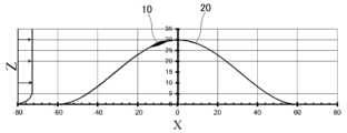
- FIG. 1 is a diagram showing an example of the shape of a surface to which the peeling suppression device according to this embodiment is applied.
- the peeling suppression device 10 is installed on the surface of the surface 20 as shown in the figure.
- the peeling suppression device 10 may be molded integrally with the surface 20, may be molded by processing the surface 20, or may be attached to the surface 20 afterwards.
- the positional relationship of each part may be described using a three-dimensional orthogonal coordinate system of the x-axis, y-axis, and z-axis.
- the surface 20 may be, for example, the surface of a moving body.
- the surface 20 has a hump shape.
- the height of the illustrated hump shape is 30 mm (millimeters).
- the fluid flows in the x-axis direction.
- the separation suppression device 10 is attached to a location where the pressure of the fluid decreases near the separation suppression device 10.
- the location where the forward pressure gradient of the surface pressure of the fluid decreases may be, for example, a location where a positive pressure gradient (reverse pressure gradient) exists in the wake.
- the separation suppression device 10 is provided at a location where the forward pressure gradient of the fluid decreases, thereby promoting turbulent transition, and by injecting momentum near the surface, separation of the fluid flow is suppressed and pressure resistance is reduced.
- the location where the separation suppression device 10 according to this embodiment is attached is not limited to the example shown in the figure, and may be attached to a location where no pressure gradient exists, for example, to promote turbulent mixing.
- FIG. 2 is an example of a cross-sectional view along the direction of fluid flow of a surface to which the peeling suppression device according to this embodiment is applied.
- this figure is a cross-sectional view in the x-z plane of FIG. 1.
- surface 20 has a hump shape with a height of 30 mm.
- the hump shape exists from a position of -60 mm to a position of +60 mm in the x-axis direction.
- peeling suppression device 10 exists at a position of approximately -15 mm to 5 mm in the x-axis direction.
- the position of approximately -15 mm to 5 mm in the x-axis direction is a location where the forward pressure gradient of the fluid decreases.
- FIG 3 is a diagram showing the change in the fluid flow direction for the pressure coefficient in the vicinity of the surface to which the peeling suppression device according to the present embodiment is applied.
- the horizontal axis of the diagram shows the position in the x-axis direction.
- the vertical axis of the diagram shows the value of the pressure coefficient.
- the diagram shows the change in the pressure coefficient Cp in the x-axis direction.
- the pressure coefficient Cp can be expressed by the following equation (2), where p bar is the static pressure on the surface of the surface 20.
- the pressure coefficient Cp is about 0.4 at a point away from the surface 20 in the negative x-axis direction, but once rises to about 0.6 to 0.7 as it approaches the surface 20.
- the pressure coefficient Cp also drops sharply at the middle of the surface 20. It is preferable that the separation suppression device 10 is provided at a location where the pressure coefficient Cp drops sharply in this way in the x-axis direction.
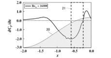
- FIG. 4 is a diagram showing the change in the pressure gradient in the fluid flow direction near a surface to which the peeling suppression device according to this embodiment is applied, in the direction of fluid flow.
- the horizontal axis of the diagram shows the position in the x-axis direction.
- the vertical axis of the diagram shows the amount of change in the pressure gradient in the x-axis direction.
- This diagram shows the change in the pressure gradient in the x-axis direction in the direction of fluid flow. As shown, the pressure gradient is negative.
- FIG. 5 is a plan view showing an example of a peeling suppression device according to this embodiment. This figure is a plan view of the x-y plane of FIG. 1.
- FIG. 6 is a perspective view showing an example of a peeling suppression device according to this embodiment. This figure is a perspective view of the vicinity of the peeling suppression device 10 of FIG. 1.
- the peeling suppression device 10 has concave or convex portions extending in the x direction, and the shape is repeated at intervals of about 30 mm in the y direction.
- the shape of the concave and convex portions extending in the x direction is maximum on the A-A cross section shown in the figure, and becomes smaller as it moves away from the A-A cross section in the plus x direction or minus x direction.
- the concave and convex portions of the peeling suppression device 10 gradually become larger along the flow, and become gradually smaller along the flow from the A-A cross section at a maximum.
- the concave and convex portions disappear at a point a certain distance in the direction of fluid flow (positive x direction or negative x direction) from the A-A cross section where the shapes of the concave and convex portions are at their maximum (for example, the B-B cross section a certain distance away in the positive x direction from the A-A cross section).
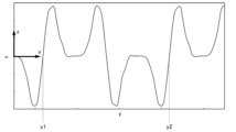
- FIG. 7 is a cross-sectional view in the span direction showing an example of a peeling suppression device according to this embodiment.
- the span direction is the direction perpendicular to the direction in which the fluid flows (i.e., the x direction), i.e., the y direction.
- the figure shows the y-z plane in FIG. 1. It can also be said that the figure shows a cross-sectional view of the A-A section shown in FIG. 6.
- the shape of the peeling suppression device 10 shown in the figure is represented diagrammatically by a function. Therefore, when the peeling suppression device 10 is molded, changes to the shape required for molding may be made.
- the peeling suppression device 10 has a shape that is repeated multiple times in the y direction, with the shape from point y1 to point y2 being one period.
- the shape of the peeling suppression device 10 may be deformed to match the shape of the surface 20.
- One end of the falling portion 31 is indicated by reference numeral 31a, and the other end by reference numeral 31b.
- One end of the rising portion 32 is indicated by reference numeral 32a, and the other end by reference numeral 32b.
- the shape of the area with vertices 31a, 32a, 31b, and 32b is approximately trapezoidal.
- the line segment connecting 31a and 32a is the upper base of the trapezoid, and may be called the upper base.
- the line segment connecting 31b and 32b is the lower base of the trapezoid, and may be called the lower base.
- the range of an approximately trapezoid is sufficient as long as it has a falling portion 31 and a rising portion 32, and also includes a shape in which each side is connected by a smooth curve such as a sine wave. Furthermore, each side forming the approximately trapezoid does not need to be a straight line, and may be a curve. As shown in the figure, the length of the lower base of the trapezoid is shorter than that of the upper base.
- the length of the upper and lower bases may be set according to the environment in which the peeling suppression device 10 is used.
- the environment in which the peeling suppression device 10 is used may be an environment according to the moving speed of the moving body on which the peeling suppression device 10 is installed, the viscosity of the fluid, etc.
- the area with vertices 31a, 32a, 31b, and 32b may be referred to as the recess 30.
- the recess 30 is provided with a protrusion 40. It can also be said that the protrusion 40 exists between the falling portion 31 and the rising portion 32.
- the shape of the protrusion 40 is a substantial trapezoid with the lower base side of the recess 30 as the lower base and the upper base side of the recess 30 as the upper base. The upper base of the trapezoid is shorter than the lower base.
- this embodiment is not limited to this example, and the shape of the protrusion 40 does not have to be a trapezoid.
- the sides 41 and 42 of the protrusion 40 may be parallel to each other.
- the protrusion 40 does not have to exist in the recess 30.
- the height h2 of the protrusions 40 is lower than the height h1 of the recesses 30.
- the upper base of the protrusions 40 is located at a lower position than the upper base of the recesses 30.
- the height h2 of the protrusions 40 is approximately half the height h1 of the recesses 30.
- symbols 45 and 46 are parts of the lower bottom of the recess 30 that do not constitute the protrusion 40.
- symbols 45 and 46 are lines parallel to the y-axis, but symbols 45 and 46 do not have to be lines parallel to the y-axis.
- these parts may or may not exist.
- the falling portion 31 and side 41 of the protrusion 40, and side 42 and the rising portion 32 may be directly connected to each other, or may be connected via symbols 45 or 46.
- the separation suppression device 10 can achieve the effects of strengthening turbulence, suppressing separation of the fluid flow, and reducing pressure resistance.
- the multiple recesses 30 that are continuous in the y direction are connected to each other via the flat portion 50.
- the flat portion 50 is the portion indicated by the line connecting the point indicated by the reference symbol 32a and the point indicated by the reference symbol 31a. It can also be said that the flat portion 50 is approximately parallel to the upper bottom of the recess 30.
- the flat portion 50 has a recess 51.
- the recess 51 has a substantially trapezoidal shape with the lower bottom side of the recess 30 as the lower base and the upper bottom side of the recess 30 as the upper base, and the upper base is longer than the lower base.
- the recess 51 is a shape that is generated by expressing the shape of the peeling suppression device 10 by a function as an example, and the peeling suppression device 10 does not need to have the recess 51 when actually forming the peeling suppression device 10.
- the period y + of the shape of the peeling suppression device 10, in which the continuous shape is arranged in a cross section perpendicular to the fluid flow as shown in the figure, is preferably calculated based on the fluid velocity, dynamic viscosity coefficient, etc.
- the period y + preferably satisfies the following formula (4) when the position in the span direction is y, the fluid velocity is u ⁇ , and the dynamic viscosity coefficient is v.
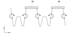
- FIG. 9 is a schematic diagram for explaining the direction of the vortex generated by the peeling suppression device according to this embodiment.
- the vortex generated by the peeling suppression device 10 will be explained with reference to this figure.
- the rotation direction of the vortex is also shown in this figure.
- a vortex as shown in the figure is generated at a location such as the B-B cross section shown in FIG. 6 after the fluid flows through the peeling suppression device 10.
- the peeling suppression device 10 the descending portion 31 and the rising portion 32 of the recess have different inclinations (inclinations of different polarities), so that vortices in different directions are generated.
- the rotation direction of the vortex generated in the rising portion 32 is different from the rotation direction of the vortex generated in the descending portion 31.
- a convex portion 40 exists within the concave portion 30.
- the peeling suppression device 10 is able to separate vortices.
- the convex portion 40 has the function of separating the vortex generated in the rising portion 32 from the vortex generated in the falling portion 31. It can also be said that by providing the convex portion 40, the concave portion 30 is able to clearly distinguish each of the separated vortices.
- FIG. 10 is a schematic diagram for explaining a first modified example of the peeling suppression device according to this embodiment.
- This figure shows a modified example in which the flat portion 50 does not have a recess 51.
- the recess 51 is not essential to the shape of the peeling suppression device 10.
- FIG. 11 is a schematic diagram for explaining a second modified example of the peeling suppression device according to this embodiment.
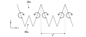
- This figure shows a modified example in which the shapes indicated by reference numerals 45 and 46 in FIG. 8 do not exist. As shown in the figure, even if the shapes indicated by reference numerals 45 and 46 do not exist, vortices with different rotation directions can be generated. Therefore, the shapes indicated by reference numerals 45 and 46 are not essential to the shape of the peeling suppression device 10.
- the peeling suppression device 10 has a recess 30a instead of the recess 30.
- the recess 30a has a protrusion 40a instead of the protrusion 40.
- the protrusion 40a differs from the protrusion 40 in that it is triangular rather than approximately trapezoidal.
- the function of the protrusion 40 is to separate vortices with different rotation directions generated by the recess 30 from each other, and it does not need to be approximately trapezoidal.
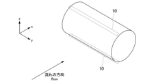
- a numerical experiment in the case where the peeling suppression device 10 is applied to a cylindrical surface.
- a cylinder having a diameter of 10 [mm] was used as the surface 20.
- the dynamic viscosity coefficient of the fluid was set to 1.512 x 10⁻⁵ (room temperature 20 [°C]) [ m2 /s].
- the sound speed was set to 343.6 (room temperature 20 [°C]) [m/s].
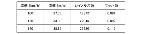
- Figure 12 shows the flow velocity [m/s], Reynolds number, and Mach number when the fluid flow velocity is 100 [km/h], 120 [km/h], and 140 [km/h].
- the numerical experiment was performed under the conditions of a Reynolds number of 25,000 and a Mach number of 0.1.
- a periodic boundary condition was applied to the span length in the span direction.
- FIG. 13 is the first diagram for explaining the effect of the separation suppression device according to this embodiment. This diagram visualizes the instantaneous flow field in the vicinity of a cylinder when the bottom surface of the cylinder is viewed from the side.
- FIG. 13(A) is a comparative example in which the separation suppression device 10 is not used
- FIG. 13(B) is an example in which the separation suppression device 10 is used on the surface of a cylinder. As is clear from the diagram, when the separation suppression device 10 is used, flow separation tends to be suppressed.
- FIG. 14 is a second diagram for explaining the effect of the separation suppression device according to this embodiment. This diagram visualizes the instantaneous flow field in the vicinity of a cylinder when the cylinder is viewed obliquely.
- FIG. 14(A) is a comparative example in which the separation suppression device 10 is not used, and
- FIG. 14(B) is an example in which the separation suppression device 10 is used on the surface of a cylinder. As is clear from the diagram, when the separation suppression device 10 is used, turbulence tends to occur earlier.
- Figure 15 is a diagram for explaining a method for evaluating the separation suppression device according to this embodiment using turbulent kinetic energy.
- the separation suppression device 10 was installed in two locations on the side of a cylinder along the height direction (y direction) of the cylinder as shown in the figure.
- the fluid flow direction was the x direction.
- FIG. 16 is a diagram for explaining the shape used in the evaluation of the peeling suppression device according to this embodiment based on turbulent kinetic energy.
- the shape of the peeling suppression device 10 according to this embodiment is shown in FIG. 16(A).
- FIGS. 16(B) and 16(C) are diagrams showing shapes used as comparative examples.
- the shape shown in FIG. 16(B) does not have rising and falling portions, as does the peeling suppression device 10. Therefore, when the shape shown in FIG. 16(B) is used, vortices with alternating phases are not generated as in the peeling suppression device 10 according to this embodiment, but vortices with the same direction are generated.
- FIG. 16(C) is a comparative example in which the height of the peeling suppression device 10 is tripled and the width is doubled.
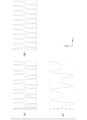
- FIG. 17 is a diagram for explaining the evaluation results of the separation suppression device according to this embodiment based on turbulent kinetic energy.
- FIG. 17(A) corresponds to FIG. 16(A)
- FIG. 17(B) corresponds to FIG. 16(B)
- FIG. 17(C) corresponds to FIG. 16(C).
- FIG. 17(D) is a comparative example in which the separation suppression device 10 is not installed (i.e., the case where only a cylinder is present).
- FIG. 17(A) vortices with alternating phases are generated, which promotes an increase in turbulence and maximizes the separation control effect.
- the separation suppression device 10 is provided at a position where the fluid flows, and suppresses separation of the flow by strengthening the turbulence.
- the position where the separation suppression device 10 is provided may be, for example, the surface of a moving body. More specifically, the position where the separation suppression device 10 is provided may be a position where the pressure of the fluid decreases, that is, the dashed line portion shown by reference numeral 21 in FIG. 4.
- the shape of the separation suppression device 10 in a cross section perpendicular to the flow of the fluid has a rising portion 32 and a falling portion 31.
- the shape of the recess 30, which is an area surrounded by the rising portion 32, the falling portion 31, the upper bottom portion, and the lower bottom portion, is a substantially trapezoid in which the length of the lower bottom portion is shorter than the upper bottom portion.
- the separation suppression device 10 can generate vortices with different rotation directions as shown in FIG. 9. By generating such vortices with different rotation directions, the separation suppression device 10 can effectively promote the turbulent transition of the fluid.
- it is possible to effectively promote the turbulent transition of a fluid by generating a pair of vortices whose rotation axis is in the flow direction and whose rotation directions are opposite to each other, which is one of the unstable solutions of the governing Navier-Stokes equations.
- the peeling suppression device 10 is very small.
- the peeling suppression device 10 may be, for example, millimeter-sized or micro-sized. Since the peeling suppression device 10 is very small compared to the vortex generators of the conventional technology, the shape of the peeling suppression device 10 itself is less likely to cause resistance. Also, since the peeling suppression device 10 is very small compared to the vortex generators of the conventional technology, it does not detract from the aesthetic appearance of the object (e.g., a moving body) on which the peeling suppression device 10 is installed, as does the vortex generators of the conventional technology.
- riblets that are used for the purpose of reducing fluid resistance.
- the riblets of the prior art and the peeling suppression device 10 of this embodiment share the common use of reducing resistance Cd (note that resistance Cd is determined by the sum of pressure resistance Cp and friction resistance Cf).
- the riblets of the prior art and the peeling suppression device 10 of this embodiment differ from each other in terms of shape, installation location, mechanism, and effect.
- FIG. 18 is a perspective view showing an example of a riblet according to the prior art.
- FIG. 18(A) shows an example of a rib having a V-shape
- FIG. 18(B) shows an example of a rib having a rectangular shape.
- the riblet according to the prior art extends along the flow direction.
- the cross section of the riblet according to the prior art in the y-z plane does not change along the direction in which the fluid flows (this is also true even if the position in the x direction changes).
- the peeling suppression device 10 according to this embodiment, as shown in FIG.
- the size of the recess 30 is maximum on the A-A cross section, and the size of the recess 30 decreases as it moves away from the A-A cross section in the plus x direction or the minus x direction.
- the riblet according to the prior art and the peeling suppression device 10 according to this embodiment have different shapes.
- FIG. 19 is a cross-sectional view in the span direction of an example of a riblet according to the conventional technology.
- FIG. 19(A) shows an example of a case where the rib has a V-shape, and corresponds to FIG. 18(A).
- FIG. 19(B) shows an example of a case where the rib has a rectangular shape, and corresponds to FIG. 18(B).
- the riblet according to the conventional technology and the peeling suppression device 10 according to this embodiment also have different cross-sectional shapes in the span direction.
- the peeling suppression device 10 has a convex portion 40 as shown in FIG. 8.
- the riblet according to the conventional technology does not have the convex portion 40 that the peeling suppression device 10 has. In this way, the riblet according to the conventional technology and the peeling suppression device 10 according to this embodiment have different shapes.
- the riblets of the conventional technology are installed in places where the flow is turbulent on the surface.
- the separation suppression device 10 is installed in places where the flow separates in the wake, etc.
- the places where the flow separates may be the dashed line portion shown as reference numeral 21 in Figure 4. Therefore, it can be said that the riblets of the conventional technology and the separation suppression device 10 of this embodiment differ from each other in terms of the installation locations.
- the riblets of the prior art suppress flow disturbances.
- the separation suppression device 10 of this embodiment amplifies flow disturbances. Therefore, it can be said that the riblets of the prior art and the separation suppression device 10 of this embodiment are different from each other in terms of mechanism.
- the riblets of the conventional technology reduce turbulent friction resistance Cf by suppressing turbulence.
- the separation suppression device 10 of this embodiment amplifies turbulence to attach the flow and reduce the pressure resistance Cp. Therefore, it can be said that the riblets of the conventional technology and the separation suppression device of this embodiment are different from each other in terms of effect.
- the turbulent transition of a fluid is effectively promoted by generating a pair of vortices with an axis of rotation in the flow direction and rotating in opposite directions, which is one of the unstable solutions of the Navier-Stokes equations, which are the governing equations. This also reduces the resistance caused by the shape of the separation suppression device itself.
Landscapes
- Engineering & Computer Science (AREA)
- Aviation & Aerospace Engineering (AREA)
- Physics & Mathematics (AREA)
- Fluid Mechanics (AREA)
- Mechanical Engineering (AREA)
- General Engineering & Computer Science (AREA)
- Structures Of Non-Positive Displacement Pumps (AREA)
Abstract
Description
本願は、2023年7月10日に日本に出願された特願2023-113035について優先権を主張し、その内容をここに援用する。

以下、本発明の態様に係る剥離抑制装置及び移動体について、好適な実施の形態を掲げ、添付の図面を参照しながら詳細に説明する。なお、本発明の態様は、これらの実施の形態に限定されるものではなく、多様な変更または改良を加えたものも含まれる。つまり、以下に記載した構成要素には、当業者が容易に想定できるもの、実質的に同一のものが含まれ、以下に記載した構成要素は適宜組み合わせることが可能である。また、本発明の要旨を逸脱しない範囲で構成要素の種々の省略、置換または変更を行うことができる。また、以下の図面においては、各構成をわかりやすくするために、各構造における縮尺および数等を、実際の構造における縮尺および数等と異ならせる場合がある。



以上説明した実施形態によれば、剥離抑制装置10は、流体が流れる位置に備えられ、乱流を強めることにより流れの剥離を抑制する。剥離抑制装置10が備えられる位置とは、例えば移動体の表面であってもよい。より具体的には、剥離抑制装置10が備えられる位置とは、流体の圧力が低下する位置、すなわち図4に符号21として示した破線部分であってもよい。また、剥離抑制装置10の、流体の流れに直交する断面における形状は、立上り部32と立下り部31とを有する。立上り部32と、立下り部31と、上底部と、下底部と、により囲まれる領域である凹部30の形状は、上底部より下底部の長さが短い略台形である。このような形状を有することにより、剥離抑制装置10は、図9に示したような、回転方向が互いに異なる渦を発生させることができる。このような回転方向が互いに異なる渦を発生させることにより、剥離抑制装置10は、流体の乱流遷移を効果的に促進することが可能となる。また、本実施形態によれば、支配方程式であるナビエ・ストークス方程式の不安定解の一つである、流れ方向に回転軸を持ち回転方向が逆の渦対を生成することで、流体の乱流遷移を効果的に促進することが可能である。
Claims (9)
- 流体が流れる位置に備えられ、乱流を強めることにより流れの剥離を抑制する剥離抑制装置であって、
前記流体の流れに直交する断面における形状は、立上り部と立下り部とを有し、
前記立上り部と、前記立下り部と、前記立上り部の一端と前記立下り部の一端とをつなぐ上底部と、前記立上り部の他端と前記立下り部の他端とをつなぐ下底部と、により囲まれる領域の形状は、前記上底部より前記下底部の長さが短い略台形である
剥離抑制装置。 - 前記立上り部において発生する渦の回転方向と、前記立下り部において発生する渦の回転方向とは互いに異なり、
前記下底部は、前記立上り部において発生する渦と、前記立下り部において発生する渦とを互いに分離する凸部を有する
請求項1に記載の剥離抑制装置。 - 前記流体の流れに直交する断面における前記凸部の形状は、前記下底部の側を下底とし、前記上底部の側を上底とし、下底より上底が短い略台形であり、
当該略台形の高さは、前記立上り部及び前記立下り部を辺とする略台形の高さより低い
請求項2に記載の剥離抑制装置。 - 前記立上り部及び前記立下り部を辺とする略台形の形状は、前記流体の流れに直交する方向に連続して備えられる
請求項1から請求項3のいずれか一項に記載の剥離抑制装置。 - 連続する複数の略台形の形状のうち、前記立上り部と、前記立下り部との間には、前記上底部と略平行な平坦部を有する
請求項4に記載の剥離抑制装置。 - 前記平坦部は、前記流体の流れに直交する断面において、前記下底部の側を下底とし、前記上底部の側を上底とし、下底より上底が長い略台形の凹部を有する
請求項5に記載の剥離抑制装置。 - 前記上底部及び前記下底部の長さは、剥離抑制装置が使用される環境に応じて設定される
請求項1から請求項3のいずれか一項に記載の剥離抑制装置。 - 連続する複数の略台形の形状が、前記流体の流れに直交する断面において配置される周期y+は、スパン方向における位置をy、前記流体の速度をuτ、動粘性係数をνとしたとき、次の(1)式を満たす
請求項4に記載の剥離抑制装置。

- 請求項1から請求項3のいずれかに記載の剥離抑制装置を備える移動体であって、
前記剥離抑制装置は、前記流体の剥離位置の近傍で前記流体による表面圧力の順圧力勾配が低下する箇所に取り付けられる
移動体。
Priority Applications (3)
| Application Number | Priority Date | Filing Date | Title |
|---|---|---|---|
| JP2025532651A JPWO2025013604A1 (ja) | 2023-07-10 | 2024-06-24 | |
| EP24839497.5A EP4745414A1 (en) | 2023-07-10 | 2024-06-24 | SEPARATION SUPPRESSION DEVICE AND MOVING BODY |
| CN202480019727.6A CN121039405A (zh) | 2023-07-10 | 2024-06-24 | 分离抑制装置和移动体 |
Applications Claiming Priority (2)
| Application Number | Priority Date | Filing Date | Title |
|---|---|---|---|
| JP2023-113035 | 2023-07-10 | ||
| JP2023113035 | 2023-07-10 |
Publications (1)
| Publication Number | Publication Date |
|---|---|
| WO2025013604A1 true WO2025013604A1 (ja) | 2025-01-16 |
Family
ID=94215144
Family Applications (1)
| Application Number | Title | Priority Date | Filing Date |
|---|---|---|---|
| PCT/JP2024/022835 Ceased WO2025013604A1 (ja) | 2023-07-10 | 2024-06-24 | 剥離抑制装置及び移動体 |
Country Status (4)
| Country | Link |
|---|---|
| EP (1) | EP4745414A1 (ja) |
| JP (1) | JPWO2025013604A1 (ja) |
| CN (1) | CN121039405A (ja) |
| WO (1) | WO2025013604A1 (ja) |
Citations (6)
| Publication number | Priority date | Publication date | Assignee | Title |
|---|---|---|---|---|
| JPS5131498A (en) | 1974-09-10 | 1976-03-17 | Kawasaki Heavy Ind Ltd | Hikikomikanona borutetsukusujenereeta |
| JP2005522644A (ja) * | 2002-04-17 | 2005-07-28 | レーム ゲゼルシャフト ミツト ベシュレンクテル ハフツング ウント コンパニー コマンディートゲゼルシャフト | 微細構造化表面を有する固体 |
| US20100108813A1 (en) * | 2007-03-30 | 2010-05-06 | Lang Amy W | passive drag modification system |
| JP2011185410A (ja) * | 2010-03-10 | 2011-09-22 | Tokyo Univ Of Agriculture & Technology | 移動体外壁及び移動体 |
| JP2019521913A (ja) * | 2016-06-20 | 2019-08-08 | スリーエム イノベイティブ プロパティズ カンパニー | 空気力学的物品及びその方法 |
| JP2023113035A (ja) | 2022-02-02 | 2023-08-15 | トヨタ自動車株式会社 | 草刈機 |
-
2024
- 2024-06-24 WO PCT/JP2024/022835 patent/WO2025013604A1/ja not_active Ceased
- 2024-06-24 CN CN202480019727.6A patent/CN121039405A/zh active Pending
- 2024-06-24 JP JP2025532651A patent/JPWO2025013604A1/ja active Pending
- 2024-06-24 EP EP24839497.5A patent/EP4745414A1/en active Pending
Patent Citations (6)
| Publication number | Priority date | Publication date | Assignee | Title |
|---|---|---|---|---|
| JPS5131498A (en) | 1974-09-10 | 1976-03-17 | Kawasaki Heavy Ind Ltd | Hikikomikanona borutetsukusujenereeta |
| JP2005522644A (ja) * | 2002-04-17 | 2005-07-28 | レーム ゲゼルシャフト ミツト ベシュレンクテル ハフツング ウント コンパニー コマンディートゲゼルシャフト | 微細構造化表面を有する固体 |
| US20100108813A1 (en) * | 2007-03-30 | 2010-05-06 | Lang Amy W | passive drag modification system |
| JP2011185410A (ja) * | 2010-03-10 | 2011-09-22 | Tokyo Univ Of Agriculture & Technology | 移動体外壁及び移動体 |
| JP2019521913A (ja) * | 2016-06-20 | 2019-08-08 | スリーエム イノベイティブ プロパティズ カンパニー | 空気力学的物品及びその方法 |
| JP2023113035A (ja) | 2022-02-02 | 2023-08-15 | トヨタ自動車株式会社 | 草刈機 |
Non-Patent Citations (1)
| Title |
|---|
| See also references of EP4745414A1 |
Also Published As
| Publication number | Publication date |
|---|---|
| EP4745414A1 (en) | 2026-05-20 |
| JPWO2025013604A1 (ja) | 2025-01-16 |
| CN121039405A (zh) | 2025-11-28 |
Similar Documents
| Publication | Publication Date | Title |
|---|---|---|
| US4706910A (en) | Combined riblet and lebu drag reduction system | |
| US6607168B1 (en) | Bearing structure with reduced tip vortex | |
| EP2270312A9 (en) | Aero- or hydrodynamic construction | |
| JP2008157465A (ja) | 表面上のくぼみ | |
| JPWO2007119696A1 (ja) | 翼 | |
| EP1710156A2 (en) | Conformal aero-adaptive nozzle / aftbody | |
| CN102762452A (zh) | 用于减少物体在流体中的流动阻力的结构 | |
| JP2009501304A (ja) | 流体力学的な力を生成する要素 | |
| JP2005529298A (ja) | 境界層の流体の流れの制御 | |
| US20160009364A1 (en) | Fluid Boundary Layer Control | |
| Sarigiguzel et al. | Experimental investigation of free-surface effects on flow characteristics of a torpedo-like geometry having a cambered nose | |
| JP2013155725A (ja) | 蒸気タービンおよび蒸気タービンの静翼 | |
| Kravtsova et al. | High-speed imaging of cavitation regimes on a round-leading-edge flat plate and NACA0015 hydrofoil | |
| KR102191628B1 (ko) | 배의 항력을 감소시키기 위한 구조물 및 그 적용 | |
| Mustak et al. | Recent advances in flow separation control of airfoils through surface grooves | |
| JP2025186438A (ja) | 構造体及び構造体を備える物体 | |
| Truong et al. | The EFD and CFD study of rudder-bulb-fin system in ship and propeller wake field of KVLCC2 tanker in calm water | |
| JP2011185410A (ja) | 移動体外壁及び移動体 | |
| JP4070385B2 (ja) | 摩擦抵抗低減船 | |
| Fung et al. | Effects of compressibility on dynamic stall | |
| KR101310961B1 (ko) | 선박의 프로펠러 보스 캡 | |
| US20020029731A1 (en) | Method of reducing frictional resistance of a hull, and frictional resistance reducing vessel | |
| CN121039405A (zh) | 分离抑制装置和移动体 | |
| KR20150145982A (ko) | 선미부 전류고정날개 | |
| JP6118865B2 (ja) | 船舶 |
Legal Events
| Date | Code | Title | Description |
|---|---|---|---|
| 121 | Ep: the epo has been informed by wipo that ep was designated in this application |
Ref document number: 24839497 Country of ref document: EP Kind code of ref document: A1 |
|
| ENP | Entry into the national phase |
Ref document number: 2025532651 Country of ref document: JP Kind code of ref document: A |
|
| WWE | Wipo information: entry into national phase |
Ref document number: 2025532651 Country of ref document: JP |
|
| WWE | Wipo information: entry into national phase |
Ref document number: 2024839497 Country of ref document: EP |
|
| NENP | Non-entry into the national phase |
Ref country code: DE |
|
| WWP | Wipo information: published in national office |
Ref document number: 2024839497 Country of ref document: EP |