WO2025009871A1 - 신규한 화합물 및 이를 포함한 유기 발광 소자 - Google Patents
신규한 화합물 및 이를 포함한 유기 발광 소자 Download PDFInfo
- Publication number
- WO2025009871A1 WO2025009871A1 PCT/KR2024/009358 KR2024009358W WO2025009871A1 WO 2025009871 A1 WO2025009871 A1 WO 2025009871A1 KR 2024009358 W KR2024009358 W KR 2024009358W WO 2025009871 A1 WO2025009871 A1 WO 2025009871A1
- Authority
- WO
- WIPO (PCT)
- Prior art keywords
- compound
- mmol
- group
- chemical formula
- under reduced
- Prior art date
- Legal status (The legal status is an assumption and is not a legal conclusion. Google has not performed a legal analysis and makes no representation as to the accuracy of the status listed.)
- Ceased
Links
Images


Classifications
-
- C—CHEMISTRY; METALLURGY
- C07—ORGANIC CHEMISTRY
- C07C—ACYCLIC OR CARBOCYCLIC COMPOUNDS
- C07C211/00—Compounds containing amino groups bound to a carbon skeleton
- C07C211/43—Compounds containing amino groups bound to a carbon skeleton having amino groups bound to carbon atoms of six-membered aromatic rings of the carbon skeleton
- C07C211/57—Compounds containing amino groups bound to a carbon skeleton having amino groups bound to carbon atoms of six-membered aromatic rings of the carbon skeleton having amino groups bound to carbon atoms of six-membered aromatic rings being part of condensed ring systems of the carbon skeleton
- C07C211/61—Compounds containing amino groups bound to a carbon skeleton having amino groups bound to carbon atoms of six-membered aromatic rings of the carbon skeleton having amino groups bound to carbon atoms of six-membered aromatic rings being part of condensed ring systems of the carbon skeleton with at least one of the condensed ring systems formed by three or more rings
-
- C—CHEMISTRY; METALLURGY
- C07—ORGANIC CHEMISTRY
- C07C—ACYCLIC OR CARBOCYCLIC COMPOUNDS
- C07C211/00—Compounds containing amino groups bound to a carbon skeleton
- C07C211/43—Compounds containing amino groups bound to a carbon skeleton having amino groups bound to carbon atoms of six-membered aromatic rings of the carbon skeleton
- C07C211/54—Compounds containing amino groups bound to a carbon skeleton having amino groups bound to carbon atoms of six-membered aromatic rings of the carbon skeleton having amino groups bound to two or three six-membered aromatic rings
-
- C—CHEMISTRY; METALLURGY
- C07—ORGANIC CHEMISTRY
- C07C—ACYCLIC OR CARBOCYCLIC COMPOUNDS
- C07C211/00—Compounds containing amino groups bound to a carbon skeleton
- C07C211/43—Compounds containing amino groups bound to a carbon skeleton having amino groups bound to carbon atoms of six-membered aromatic rings of the carbon skeleton
- C07C211/57—Compounds containing amino groups bound to a carbon skeleton having amino groups bound to carbon atoms of six-membered aromatic rings of the carbon skeleton having amino groups bound to carbon atoms of six-membered aromatic rings being part of condensed ring systems of the carbon skeleton
- C07C211/58—Naphthylamines; N-substituted derivatives thereof
-
- C—CHEMISTRY; METALLURGY
- C07—ORGANIC CHEMISTRY
- C07D—HETEROCYCLIC COMPOUNDS
- C07D307/00—Heterocyclic compounds containing five-membered rings having one oxygen atom as the only ring hetero atom
- C07D307/77—Heterocyclic compounds containing five-membered rings having one oxygen atom as the only ring hetero atom ortho- or peri-condensed with carbocyclic rings or ring systems
- C07D307/91—Dibenzofurans; Hydrogenated dibenzofurans
-
- C—CHEMISTRY; METALLURGY
- C07—ORGANIC CHEMISTRY
- C07D—HETEROCYCLIC COMPOUNDS
- C07D333/00—Heterocyclic compounds containing five-membered rings having one sulfur atom as the only ring hetero atom
- C07D333/50—Heterocyclic compounds containing five-membered rings having one sulfur atom as the only ring hetero atom condensed with carbocyclic rings or ring systems
- C07D333/76—Dibenzothiophenes
-
- C—CHEMISTRY; METALLURGY
- C09—DYES; PAINTS; POLISHES; NATURAL RESINS; ADHESIVES; COMPOSITIONS NOT OTHERWISE PROVIDED FOR; APPLICATIONS OF MATERIALS NOT OTHERWISE PROVIDED FOR
- C09K—MATERIALS FOR MISCELLANEOUS APPLICATIONS, NOT PROVIDED FOR ELSEWHERE
- C09K11/00—Luminescent materials, e.g. electroluminescent or chemiluminescent
- C09K11/06—Luminescent materials, e.g. electroluminescent or chemiluminescent containing organic luminescent materials
-
- H—ELECTRICITY
- H10—SEMICONDUCTOR DEVICES; ELECTRIC SOLID-STATE DEVICES NOT OTHERWISE PROVIDED FOR
- H10K—ORGANIC ELECTRIC SOLID-STATE DEVICES
- H10K50/00—Organic light-emitting devices
- H10K50/10—OLEDs or polymer light-emitting diodes [PLED]
- H10K50/11—OLEDs or polymer light-emitting diodes [PLED] characterised by the electroluminescent [EL] layers
-
- H—ELECTRICITY
- H10—SEMICONDUCTOR DEVICES; ELECTRIC SOLID-STATE DEVICES NOT OTHERWISE PROVIDED FOR
- H10K—ORGANIC ELECTRIC SOLID-STATE DEVICES
- H10K50/00—Organic light-emitting devices
- H10K50/10—OLEDs or polymer light-emitting diodes [PLED]
- H10K50/14—Carrier transporting layers
- H10K50/15—Hole transporting layers
-
- H—ELECTRICITY
- H10—SEMICONDUCTOR DEVICES; ELECTRIC SOLID-STATE DEVICES NOT OTHERWISE PROVIDED FOR
- H10K—ORGANIC ELECTRIC SOLID-STATE DEVICES
- H10K85/00—Organic materials used in the body or electrodes of devices covered by this subclass
- H10K85/60—Organic compounds having low molecular weight
-
- H—ELECTRICITY
- H10—SEMICONDUCTOR DEVICES; ELECTRIC SOLID-STATE DEVICES NOT OTHERWISE PROVIDED FOR
- H10K—ORGANIC ELECTRIC SOLID-STATE DEVICES
- H10K85/00—Organic materials used in the body or electrodes of devices covered by this subclass
- H10K85/60—Organic compounds having low molecular weight
- H10K85/615—Polycyclic condensed aromatic hydrocarbons, e.g. anthracene
- H10K85/622—Polycyclic condensed aromatic hydrocarbons, e.g. anthracene containing four rings, e.g. pyrene
-
- H—ELECTRICITY
- H10—SEMICONDUCTOR DEVICES; ELECTRIC SOLID-STATE DEVICES NOT OTHERWISE PROVIDED FOR
- H10K—ORGANIC ELECTRIC SOLID-STATE DEVICES
- H10K85/00—Organic materials used in the body or electrodes of devices covered by this subclass
- H10K85/60—Organic compounds having low molecular weight
- H10K85/631—Amine compounds having at least two aryl rest on at least one amine-nitrogen atom, e.g. triphenylamine
-
- H—ELECTRICITY
- H10—SEMICONDUCTOR DEVICES; ELECTRIC SOLID-STATE DEVICES NOT OTHERWISE PROVIDED FOR
- H10K—ORGANIC ELECTRIC SOLID-STATE DEVICES
- H10K85/00—Organic materials used in the body or electrodes of devices covered by this subclass
- H10K85/60—Organic compounds having low molecular weight
- H10K85/631—Amine compounds having at least two aryl rest on at least one amine-nitrogen atom, e.g. triphenylamine
- H10K85/633—Amine compounds having at least two aryl rest on at least one amine-nitrogen atom, e.g. triphenylamine comprising polycyclic condensed aromatic hydrocarbons as substituents on the nitrogen atom
-
- H—ELECTRICITY
- H10—SEMICONDUCTOR DEVICES; ELECTRIC SOLID-STATE DEVICES NOT OTHERWISE PROVIDED FOR
- H10K—ORGANIC ELECTRIC SOLID-STATE DEVICES
- H10K85/00—Organic materials used in the body or electrodes of devices covered by this subclass
- H10K85/60—Organic compounds having low molecular weight
- H10K85/631—Amine compounds having at least two aryl rest on at least one amine-nitrogen atom, e.g. triphenylamine
- H10K85/636—Amine compounds having at least two aryl rest on at least one amine-nitrogen atom, e.g. triphenylamine comprising heteroaromatic hydrocarbons as substituents on the nitrogen atom
-
- H—ELECTRICITY
- H10—SEMICONDUCTOR DEVICES; ELECTRIC SOLID-STATE DEVICES NOT OTHERWISE PROVIDED FOR
- H10K—ORGANIC ELECTRIC SOLID-STATE DEVICES
- H10K85/00—Organic materials used in the body or electrodes of devices covered by this subclass
- H10K85/60—Organic compounds having low molecular weight
- H10K85/649—Aromatic compounds comprising a hetero atom
- H10K85/657—Polycyclic condensed heteroaromatic hydrocarbons
- H10K85/6574—Polycyclic condensed heteroaromatic hydrocarbons comprising only oxygen in the heteroaromatic polycondensed ring system, e.g. cumarine dyes
-
- H—ELECTRICITY
- H10—SEMICONDUCTOR DEVICES; ELECTRIC SOLID-STATE DEVICES NOT OTHERWISE PROVIDED FOR
- H10K—ORGANIC ELECTRIC SOLID-STATE DEVICES
- H10K85/00—Organic materials used in the body or electrodes of devices covered by this subclass
- H10K85/60—Organic compounds having low molecular weight
- H10K85/649—Aromatic compounds comprising a hetero atom
- H10K85/657—Polycyclic condensed heteroaromatic hydrocarbons
- H10K85/6576—Polycyclic condensed heteroaromatic hydrocarbons comprising only sulfur in the heteroaromatic polycondensed ring system, e.g. benzothiophene
-
- C—CHEMISTRY; METALLURGY
- C07—ORGANIC CHEMISTRY
- C07C—ACYCLIC OR CARBOCYCLIC COMPOUNDS
- C07C2602/00—Systems containing two condensed rings
- C07C2602/02—Systems containing two condensed rings the rings having only two atoms in common
- C07C2602/04—One of the condensed rings being a six-membered aromatic ring
- C07C2602/10—One of the condensed rings being a six-membered aromatic ring the other ring being six-membered, e.g. tetraline
-
- C—CHEMISTRY; METALLURGY
- C07—ORGANIC CHEMISTRY
- C07C—ACYCLIC OR CARBOCYCLIC COMPOUNDS
- C07C2603/00—Systems containing at least three condensed rings
- C07C2603/02—Ortho- or ortho- and peri-condensed systems
- C07C2603/40—Ortho- or ortho- and peri-condensed systems containing four condensed rings
- C07C2603/42—Ortho- or ortho- and peri-condensed systems containing four condensed rings containing only six-membered rings
- C07C2603/48—Chrysenes; Hydrogenated chrysenes
Definitions
- the present invention relates to a novel compound and an organic light-emitting device comprising the same.
- the organic luminescence phenomenon refers to the phenomenon of converting electrical energy into light energy using organic materials.
- Organic light-emitting devices utilizing the organic luminescence phenomenon have a wide viewing angle, excellent contrast, fast response time, and excellent brightness, driving voltage, and response speed characteristics, so much research is being conducted.
- Organic light-emitting devices generally have a structure including an anode, a cathode, and an organic layer between the anode and the cathode.
- the organic layer is often composed of a multilayer structure composed of different materials in order to increase the efficiency and stability of the organic light-emitting device, and may be composed of, for example, a hole injection layer, a hole transport layer, a light-emitting layer, an electron transport layer, an electron injection layer, etc.
- Patent Document 0001 Korean Patent Publication No. 10-2000-0051826
- the present invention relates to a novel compound and an organic light-emitting device comprising the same.
- the present invention provides a compound represented by the following chemical formula 1:
- L 1 and L 2 are each independently a single bond, or a substituted or unsubstituted C 6-60 arylene,
- R 1 is each independently hydrogen or deuterium
- Ar 1 is a substituted or unsubstituted C 6-60 aryl, or a C 2-60 heteroaryl comprising at least one heteroatom selected from the group consisting of substituted or unsubstituted N, O and S, provided that substituted or unsubstituted dimethylfluorenyl, diphenylfluorenyl, and spirobifluorenyl in Ar 1 are excluded,
- Ar 2 is a substituent represented by the following chemical formula 2,
- R 2 is bonded to L 2 , and the others are each independently hydrogen or deuterium,
- a is an integer from 0 to 2
- b is an integer from 0 to 4,
- c is an integer from 0 to 7.
- the present invention provides an organic light-emitting device including a first electrode; a second electrode provided opposite the first electrode; and at least one organic layer provided between the first electrode and the second electrode, wherein at least one of the organic layers includes a compound represented by the chemical formula 1.
- the compound represented by the above-described chemical formula 1 can be used as a material of an organic layer of an organic light-emitting device, and can improve efficiency, low driving voltage, and/or lifespan characteristics in the organic light-emitting device.
- the compound represented by the above-described chemical formula 1 can be used as a hole injection, hole transport, hole injection and transport, luminescence, electron transport, or electron injection material.
- Figure 1 illustrates an example of an organic light-emitting device composed of a substrate (1), an anode (2), a light-emitting layer (3), and a cathode (4).
- Figure 2 illustrates an example of an organic light-emitting device composed of a substrate (1), an anode (2), a hole injection layer (5), a hole transport layer (6), a hole transport auxiliary layer (7), a light-emitting layer (3), a hole blocking layer (8), an electron injection and transport layer (9), and a cathode (4).
- substituted or unsubstituted means a group unsubstituted or substituted with one or more substituents selected from the group consisting of deuterium; a halogen group; a cyano group; a nitro group; a hydroxy group; a carbonyl group; an ester group; an imide group; an amino group; a phosphine oxide group; an alkoxy group; an aryloxy group; an alkylthioxy group; an arylthioxy group; an alkylsulfoxy group; an arylsulfoxy group; a silyl group; a boron group; an alkyl group; a cycloalkyl group; an alkenyl group; an aryl group; an aralkyl group; an aralkenyl group; an alkylaryl group; an alkylamine group; an aralkylamine group; a heteroarylamine group; an arylamine group;
- a substituent having two or more substituents connected may be a biphenylyl group. That is, the biphenylyl group may also be an aryl group, and may be interpreted as a substituent having two phenyl groups connected.
- substituted or unsubstituted may be understood to mean “unsubstituted or substituted with one or more substituents selected from the group consisting of deuterium, halogen, cyano, C 1-10 alkyl, C 1-10 alkoxy, and C 6-20 aryl”; or “unsubstituted or substituted with one or more substituents selected from the group consisting of deuterium, halogen, cyano, methyl, ethyl, phenyl, and naphthyl.”
- substituted with one or more substituents in the present specification may be understood to mean “substituted with 1 to the maximum number of substitutable hydrogens.”
- substituted with one or more substituents herein may be understood to mean “substituted with one to five substituents", or “substituted with one or two substituents.”
- the carbon number of the carbonyl group is not particularly limited, but is preferably 1 to 40 carbon atoms. Specifically, it can be a substituent having the following structure, but is not limited thereto.
- the ester group may have the oxygen of the ester group substituted with a straight-chain, branched-chain or cyclic alkyl group having 1 to 25 carbon atoms or an aryl group having 6 to 25 carbon atoms.
- the ester group may have a substituent of the following structural formula, but is not limited thereto.
- the number of carbon atoms in the imide group is not particularly limited, but is preferably 1 to 25 carbon atoms. Specifically, it can be a substituent having the following structure, but is not limited thereto.
- a substituted or unsubstituted silyl group means -Si(Z 1 )(Z 2 )(Z 3 ), wherein Z 1 , Z 2 and Z 3 can each independently be hydrogen, deuterium, a substituted or unsubstituted C 1-60 alkyl, a substituted or unsubstituted C 1-60 haloalkyl, a substituted or unsubstituted C 2-60 alkenyl, a substituted or unsubstituted C 2-60 haloalkenyl, or a substituted or unsubstituted C 6-60 aryl.
- Z 1 , Z 2 and Z 3 can each independently be hydrogen, deuterium, a substituted or unsubstituted C 1-10 alkyl, a substituted or unsubstituted C 1-10 haloalkyl, a substituted or unsubstituted C 1-10 haloalkyl, or a substituted or unsubstituted C 6-20 aryl.
- silyl group examples include, but are not limited to, a trimethylsilyl group, a triethylsilyl group, a t-butyldimethylsilyl group, a vinyldimethylsilyl group, a propyldimethylsilyl group, a triphenylsilyl group, a diphenylsilyl group, and a phenylsilyl group.
- the boron group specifically includes, but is not limited to, a trimethyl boron group, a triethyl boron group, a t-butyldimethyl boron group, a triphenyl boron group, a phenyl boron group, etc.
- halogen groups include fluoro, chloro, bromo, or iodo.
- the alkyl group may be linear or branched, and the number of carbon atoms is not particularly limited, but is preferably 1 to 40. According to one embodiment, the number of carbon atoms of the alkyl group is 1 to 20. According to another embodiment, the number of carbon atoms of the alkyl group is 1 to 10.
- alkyl group examples include methyl, ethyl, propyl, n-propyl, isopropyl, butyl, n-butyl, isobutyl, tert-butyl, sec-butyl, 1-methyl-butyl, 1-ethylbutyl, pentyl, n-pentyl, isopentyl, neopentyl, tert-pentyl, 1-ethyl-propyl, 1,1-dimethylpropyl, hexyl, n-hexyl, 1-methylpentyl, 2-methylpentyl, 4-methyl-2-pentyl, 3,3-dimethylbutyl, 2-ethylbutyl, heptyl, n-heptyl, isohexyl, 1-methylhexyl, 2-methylhexyl, 3-methylhexyl, 4-methylhexyl, 5-methylhexyl,
- the alkenyl group may be linear or branched, and the carbon number is not particularly limited, but is preferably 2 to 40. According to one embodiment, the carbon number of the alkenyl group is 2 to 20. According to another embodiment, the carbon number of the alkenyl group is 2 to 10. According to another embodiment, the carbon number of the alkenyl group is 2 to 6.
- Specific examples include, but are not limited to, vinyl, 1-propenyl, isopropenyl, 1-butenyl, 2-butenyl, 3-butenyl, 1-pentenyl, 2-pentenyl, 3-pentenyl, 3-methyl-1-butenyl, 1,3-butadienyl, allyl, 1-phenylvinyl-1-yl, 2-phenylvinyl-1-yl, 2,2-diphenylvinyl-1-yl, 2-phenyl-2-(naphthyl-1-yl)vinyl-1-yl, 2,2-bis(diphenyl-1-yl)vinyl-1-yl, stilbenyl, and styrenyl.
- the alicyclic group refers to a monovalent substituent derived from a saturated or unsaturated hydrocarbon ring compound that contains only carbon as a ring-forming atom and does not have aromaticity, and is understood to encompass both monocyclic and condensed polycyclic compounds.
- the alicyclic group has 3 to 60 carbon atoms.
- the cycloalkyl group has 3 to 30 carbon atoms.
- the cycloalkyl group has 3 to 20 carbon atoms.
- alicyclic groups include a monocyclic group such as a cycloalkyl group, a bridged hydrocarbon group, a spiro hydrocarbon group, a substituent derived from a hydrogenated derivative of an aromatic hydrocarbon compound, and the like.
- examples of the cycloalkyl group include, but are not limited to, cyclopropyl, cyclobutyl, cyclopentyl, 3-methylcyclopentyl, 2,3-dimethylcyclopentyl, cyclohexyl, 3-methylcyclohexyl, 4-methylcyclohexyl, 2,3-dimethylcyclohexyl, 3,4,5-trimethylcyclohexyl, 4-tert-butylcyclohexyl, cycloheptyl, cyclooctyl, and the like.
- hydrocarbon group spanning the bridge examples include, but are not limited to, bicyclo[1.1.0]butyl, bicyclo[2.2.1]heptyl, bicyclo[4.2.0]octa-1,3,5-trienyl, adamantyl, and decalinyl.
- examples of the spiro ring hydrocarbon group include, but are not limited to, spiro[3.4]octyl and spiro[5.5]undecanyl.
- a substituent derived from a hydrogenated derivative of the above aromatic hydrocarbon compound means a substituent derived from a compound in which hydrogen is added to a part of an unsaturated bond of a monocyclic or polycyclic aromatic hydrocarbon compound, and examples of such substituents include, but are not limited to, 1 H -indenyl, 2 H -indenyl, 4 H -indenyl, 2,3-dihydro-1 H -indenyl, 1,4-dihydronaphthalenyl, 1,2,3,4-tetrahydronaphthalenyl, 6,7,8,9-tetrahydro-5 H -benzo[7]annulenyl, 6,7-dihydro-5 H -benzocycloheptenyl, and the like.
- an aryl group is understood to mean a substituent derived from a monocyclic or condensed polycyclic compound having aromaticity and containing only carbon as a ring-forming atom, and the carbon number is not particularly limited, but is preferably 6 to 60. According to one embodiment, the aryl group has 6 to 30 carbon atoms. According to one embodiment, the aryl group has 6 to 20 carbon atoms.
- the aryl group may be a monocyclic aryl group, such as a phenyl group, a biphenylyl group, or a terphenylyl group, but is not limited thereto.
- the polycyclic aryl group may be a naphthyl group, an anthracenyl group, a phenanthryl group, a pyrenyl group, a perylenyl group, a chrysenyl group, or a fluorenyl group, but is not limited thereto.
- the fluorenyl group may be substituted, and two substituents may be combined with each other to form a spiro structure.
- the fluorenyl group is substituted, It can be, but is not limited to, the following.
- a heterocyclic group means a monovalent substituent derived from a monocyclic or condensed polycyclic compound further containing one or more heteroatoms selected from O, N, Si and S in addition to carbon as a ring-forming atom, and is understood to encompass both a substituent having aromaticity and a substituent not having aromaticity.
- the heterocyclic group has 2 to 60 carbon atoms.
- the heterocyclic group has 2 to 30 carbon atoms.
- the heterocyclic group has 2 to 20 carbon atoms. Examples of such heterocyclic groups include a heteroaryl group, a substituent derived from a hydrogenated derivative of a heteroaromatic compound, and the like.
- the heteroaryl group refers to a substituent derived from a monocyclic or condensed polycyclic compound which further includes at least one heteroatom selected from N, O and S in addition to carbon as a ring-forming atom, and refers to a substituent having aromaticity.
- the heteroaryl group has 2 to 60 carbon atoms.
- the heteroaryl group has 2 to 30 carbon atoms.
- the heteroaryl group has 2 to 20 carbon atoms.
- heteroaryl group examples include a thiophenyl group, a furanyl group, a pyrrolyl group, an imidazolyl group, a thiazolyl group, an oxazolyl group, an oxadiazolyl group, a triazolyl group, a pyridinyl group, a bipyridinyl group, a pyrimidinyl group, a triazinyl group, an acridinyl group, a pyridazinyl group, a pyrazinyl group, a quinolinyl group, a quinazolinyl group, a quinoxalinyl group, a phthalazinyl group, a pyridopyrimidinyl group, a pyridopyrazinyl group, an isoquinolinyl group, an indolyl group, a carbazolyl group, a benzoxazolyl group, a thi
- a substituent derived from a hydrogenated derivative of the heteroaromatic compound means a substituent derived from a compound in which hydrogen is added to a part of an unsaturated bond of a monocyclic or polycyclic heteroaromatic compound, and examples of such a substituent include, but are not limited to, 1,3-dihydroisobenzofuranyl, 2,3-dihydrobenzofuranyl, 1,3-dihydrobenzo[c ]thiophenyl, 2,3-dihydro[b ] thiophenyl , etc.
- the aryl group among the aralkyl group, the aralkenyl group, the alkylaryl group, the arylamine group, and the arylsilyl group is the same as the examples of the aryl group described above.
- the alkyl group among the aralkyl group, the alkylaryl group, and the alkylamine group is the same as the examples of the alkyl group described above.
- the heteroaryl among the heteroarylamine may be applied with the description of the heteroaryl described above.
- the alkenyl group among the aralkenyl group is the same as the examples of the alkenyl group described above.
- the description of the aryl group described above may be applied with the exception that arylene is a divalent group.
- the description of the heteroaryl described above may be applied with the exception that heteroarylene is a divalent group.
- the description of the aryl group or the cycloalkyl group described above may be applied with the exception that the hydrocarbon ring is not a monovalent group but is formed by combining two substituents.
- the description of the heteroaryl described above may be applied, except that the heterocycle is not monovalent and is formed by combining two substituents.
- deuterated or deuterium substituted means that at least one of the substitutable hydrogens in the compound, divalent linking group or monovalent substituent is replaced with deuterium.
- unsubstituted or substituted with deuterium or “substituted or unsubstituted with deuterium” means “unsubstituted or substituted with 1 to 9 deuterium atoms”.
- unsubstituted or substituted with deuterium phenanthryl can be understood to mean “unsubstituted or substituted with 1 to 9 deuterium atoms", considering that the maximum number of hydrogen atoms that can be substituted with deuterium in the phenanthryl structure is 9.
- deuterated structure is meant to encompass compounds of all structures, divalent linkages or monovalent substituents in which at least one hydrogen is replaced by a deuterium.
- deuterated structure of phenyl can be understood to refer to monovalent substituents of all structures in which at least one substitutable hydrogen in the phenyl group is replaced by a deuterium, as follows.
- the "deuterium substitution rate” or “deuteration degree” of a compound means the ratio of the number of substituted deuteriums to the total number of hydrogens that can exist in the compound (the sum of the number of hydrogens replaceable with deuterium in the compound and the number of substituted deuteriums) calculated as a percentage. Therefore, when the "deuterium substitution rate” or “deuteration degree” of a compound is "K%,” it means that K% of the hydrogens replaceable with deuterium in the compound are replaced with deuterium.
- the "deuterium substitution rate” or “deuteration degree” can be obtained by obtaining the number of substituted deuterium in the compound through MALDI-TOF MS analysis, and then calculating the ratio of the number of substituted deuterium to the total number of hydrogens that can exist in the compound as a percentage.
- the present invention provides a compound represented by the chemical formula 1.
- the chemical formula 1 is represented by the following chemical formula 1-1 or 1-2:
- L 1 , L 2 , R 1 , Ar 1 , Ar 2 , D, a, b and c are as defined above.
- L 1 and L 2 are each independently a single bond, or phenylene which is unsubstituted or substituted with one or more deuterium atoms.
- both L 1 and L 2 are single bonds
- L 1 is phenylene which is unsubstituted or substituted with one or more deuterium atoms, and L 2 is a single bond; or
- Both L 1 and L 2 are phenylene, which is unsubstituted or substituted with one or more deuterium atoms.
- the phenylene may be unsubstituted or substituted with 1, 2, 3, or 4 deuterium.
- Ar 1 is phenyl, biphenylyl, tert-butylphenyl, naphthyl, phenyl naphthyl, naphthyl phenyl, naphthyl naphthyl, phenanthryl, dibenzofuranyl or dibenzothiophenyl; wherein Ar 1 is unsubstituted or substituted with one or more deuterium atoms.
- Ar 1 is one selected from the group consisting of: and deuterated structures thereof.
- chemical formula 2 is represented by any one of the following chemical formulas 2-1 to 2-6:
- R 2 is independently hydrogen or deuterium.
- one of R 2 is bonded to L 2 and the rest are all hydrogen, or all deuterium.
- a, b, and c represent the number of D, where a is 0, 1, or 2, b is 0, 1, 2, 3, or 4, and c is 0, 1, 2, 3, 4, 5, 6, or 7.
- the compound represented by the above chemical formula 1 can be manufactured by a manufacturing method as shown in the following reaction scheme 1, and the remaining compounds can also be manufactured similarly.
- Ar 1 , Ar 2 , L 1 , L 2 , R 1 , D, a, b and c are as defined in the above chemical formula 1, Y is halogen, and preferably Y is bromo or chloro.
- the above reaction is preferably performed in the presence of a palladium catalyst and a base as an amine substitution reaction, and the reactor for the above reaction can be changed as known in the art.
- the above manufacturing method can be more specifically described in the manufacturing example described below.
- the present invention provides an organic light-emitting device comprising a compound represented by the chemical formula 1.
- the present invention provides an organic light-emitting device comprising a first electrode; a second electrode provided opposite the first electrode; and at least one organic layer provided between the first electrode and the second electrode, wherein at least one layer of the organic layers comprises a compound represented by the chemical formula 1.
- the organic layer of the organic light-emitting device of the present invention may be formed as a single-layer structure, but may be formed as a multilayer structure in which two or more organic layers are laminated.
- the organic light-emitting device of the present invention may have a structure including a hole injection layer, a hole transport layer, a hole transport auxiliary layer, a light-emitting layer, an electron transport layer, an electron injection layer, etc. as the organic layers.
- the structure of the organic light-emitting device is not limited thereto and may include a smaller number of organic layers.
- the organic layer may include a light-emitting layer, and in this case, the organic layer including the compound represented by the chemical formula 1 may be a light-emitting layer.
- the organic layer may include a hole injection layer, a hole transport layer, a hole transport assisting layer, an emitting layer, a hole blocking layer, and an electron injection and transport layer, wherein the organic layer including the compound may be a emitting layer.
- the organic light-emitting device according to the present invention may be an organic light-emitting device having a structure (normal type) in which an anode, one or more organic layers, and a cathode are sequentially laminated on a substrate.
- the organic light-emitting device according to the present invention may be an organic light-emitting device having a structure (inverted type) in which a cathode, one or more organic layers, and an anode are sequentially laminated on a substrate.
- FIGS. 1 and 2 the structure of an organic light-emitting device according to an embodiment of the present invention is exemplified in FIGS. 1 and 2.
- Figure 1 illustrates an example of an organic light-emitting device composed of a substrate (1), an anode (2), a light-emitting layer (3), and a cathode (4).
- the compound represented by the chemical formula 1 may be included in the light-emitting layer.
- FIG. 2 illustrates an example of an organic light-emitting device composed of a substrate (1), an anode (2), a hole injection layer (5), a hole transport layer (6), a hole transport auxiliary layer (7), an emitting layer (3), a hole blocking layer (8), an electron injection and transport layer (9), and a cathode (4).
- the compound represented by the chemical formula 1 may be included in the hole transport auxiliary layer.
- the organic light-emitting device according to the present invention can be manufactured using materials and methods known in the art, except that at least one of the organic layers includes a compound represented by the chemical formula 1.
- the organic layers can be formed of the same material or different materials.
- the organic light-emitting device can be manufactured by sequentially stacking a first electrode, an organic layer, and a second electrode on a substrate.
- a PVD (physical vapor deposition) method such as sputtering or e-beam evaporation is used to deposit a metal or a conductive metal oxide or an alloy thereof on the substrate to form an anode, and then an organic layer including a hole injection layer, a hole transport layer, a light-emitting layer, and an electron transport layer is formed thereon, and then a material that can be used as a cathode is deposited thereon, thereby manufacturing the device.
- the organic light-emitting device can be manufactured by sequentially depositing a cathode material, an organic layer, and an anode material on the substrate.
- the compound represented by the above chemical formula 1 can be formed into an organic layer by a solution coating method as well as a vacuum deposition method when manufacturing an organic light-emitting device.
- the solution coating method means spin coating, dip coating, doctor blading, inkjet printing, screen printing, spraying, roll coating, etc., but is not limited thereto.
- an organic light-emitting device can be manufactured by sequentially depositing an organic layer and an anode material from a cathode material on a substrate (WO 2003/012890).
- the manufacturing method is not limited to this.
- the first electrode is an anode and the second electrode is a cathode, or the first electrode is a cathode and the second electrode is an anode.
- anode material a material having a high work function is generally preferred so that hole injection into the organic layer can be smooth.
- Specific examples of the above anode material include, but are not limited to, metals such as vanadium, chromium, copper, zinc, and gold, or alloys thereof; metal oxides such as zinc oxide, indium oxide, indium tin oxide (ITO), and indium zinc oxide (IZO); combinations of metals and oxides such as ZnO:Al or SnO 2 :Sb; and conductive polymers such as poly(3-methylthiophene), poly[3,4-(ethylene-1,2-dioxy)thiophene] (PEDOT), polypyrrole, and polyaniline.
- metals such as vanadium, chromium, copper, zinc, and gold, or alloys thereof
- metal oxides such as zinc oxide, indium oxide, indium tin oxide (ITO), and indium zinc oxide (IZO)
- combinations of metals and oxides such as ZnO:Al
- the cathode material is preferably a material having a low work function to facilitate electron injection into the organic layer.
- Specific examples of the cathode material include, but are not limited to, metals such as magnesium, calcium, sodium, potassium, titanium, indium, yttrium, lithium, gadolinium, aluminum, silver, tin, and lead, or alloys thereof; multilayered materials such as LiF/Al or LiO 2 /Al.
- the above hole injection layer is a layer that injects holes from the electrode
- the hole injection material is preferably a compound that has the ability to transport holes, has an excellent hole injection effect at the anode, an excellent hole injection effect for the light-emitting layer or the light-emitting material, prevents movement of excitons generated in the light-emitting layer to the electron injection layer or the electron injection material, and further has excellent thin film forming ability.
- the HOMO (highest occupied molecular orbital) of the hole injection material is between the work function of the anode material and the HOMO of the surrounding organic layer.
- hole injection material examples include, but are not limited to, metal porphyrin, oligothiophene, arylamine series organic compounds, hexanitrilehexaazatriphenylene series organic compounds, quinacridone series organic compounds, perylene series organic compounds, anthraquinone, and conductive polymers of polyaniline and polythiophene series.
- the above hole transport layer is a layer that receives holes from the hole injection layer and transports the holes to the light-emitting layer.
- a hole transport material that can transport holes from the anode or the hole injection layer and transfer them to the light-emitting layer is suitable, and a material having high hole mobility is suitable. Specific examples include, but are not limited to, arylamine-based organic compounds, conductive polymers, and block copolymers having both conjugated and non-conjugated portions.
- the electron blocking layer is formed on the hole transport layer, preferably provided in contact with the light-emitting layer, and refers to a layer that improves the efficiency of the organic light-emitting device by controlling hole mobility and preventing excessive movement of electrons to increase the hole-electron coupling probability.
- the electron blocking layer includes an electron blocking material, and examples of such an electron blocking material include, but are not limited to, an organic material of the arylamine series.
- the above-mentioned hole transport auxiliary layer is a layer located between the hole transport layer and the light-emitting layer.
- the hole transport auxiliary layer By including the hole transport auxiliary layer, holes are transported more smoothly from the hole transport layer to the light-emitting layer, and excitons are confined within the light-emitting layer, preventing light leakage, so that the organic light-emitting device has an excellent light-emitting efficiency.
- the compound represented by the above-mentioned chemical formula 1 can be used as the hole transport auxiliary material.
- the above-mentioned light-emitting material is a material that can emit light in the visible light range by transporting holes and electrons from the hole transport layer and the electron transport layer respectively and combining them, and a material having good quantum efficiency for fluorescence or phosphorescence is preferable.
- Specific examples thereof include, but are not limited to, 8-hydroxy-quinoline aluminum complex (Alq 3 ); carbazole compounds; dimerized styryl compounds; BAlq; 10-hydroxybenzo quinoline-metal compounds; benzoxazole, benzthiazole, and benzimidazole compounds; poly(p-phenylenevinylene) (PPV) polymers; spiro compounds; polyfluorene, rubrene, etc.
- the above-mentioned light-emitting layer may include a host material and a dopant material.
- the host material may include a condensed aromatic ring derivative or a heterocyclic compound.
- the condensed aromatic ring derivative may include anthracene derivatives, pyrene derivatives, naphthalene derivatives, pentacene derivatives, phenanthrene compounds, fluoranthene compounds, etc.
- the heterocyclic compound may include, but is not limited to, carbazole derivatives, dibenzofuran derivatives, ladder-type furan compounds, pyrimidine derivatives, etc.
- Dopant materials include aromatic amine derivatives, styrylamine compounds, boron complexes, fluoranthene compounds, metal complexes, etc.
- aromatic amine derivatives are condensed aromatic ring derivatives having a substituted or unsubstituted arylamino group, such as pyrene, anthracene, chrysene, periflanthene, etc.
- styrylamine compounds are compounds in which at least one arylvinyl group is substituted in a substituted or unsubstituted arylamine, and one or more substituents selected from the group consisting of an aryl group, a silyl group, an alkyl group, a cycloalkyl group, and an arylamino group are substituted or unsubstituted.
- substituents selected from the group consisting of an aryl group, a silyl group, an alkyl group, a cycloalkyl group, and an arylamino group are substituted or unsubstituted.
- styrylamine, styryldiamine, styryltriamine, styryltetraamine, etc. but are not limited thereto.
- metal complexes include iridium complexes, platinum complexes, etc., but are not limited thereto.
- the above hole-blocking layer refers to a layer formed on a light-emitting layer, preferably provided in contact with the light-emitting layer, to control electron mobility, prevent excessive movement of holes, and increase the hole-electron coupling probability, thereby improving the efficiency of the organic light-emitting device.
- the hole-blocking layer includes a hole-blocking material, and examples of such hole-blocking materials include compounds having an electron-withdrawing group introduced therein, such as azine derivatives including triazine; triazole derivatives; oxadiazole derivatives; phenanthroline derivatives; and phosphine oxide derivatives, but are not limited thereto.
- the above electron injection and transport layer is a layer that simultaneously performs the roles of an electron transport layer and an electron injection layer that injects electrons from an electrode and transports the received electrons to the light-emitting layer, and is formed on the light-emitting layer or the hole blocking layer.
- the electron injection and transport material a material that can well inject electrons from the cathode and transfer them to the light-emitting layer is suitable, and a material with high electron mobility is suitable.
- the compound represented by the above chemical formula 1 can be used as the electron injection and transport layer material.
- additional electron injection and transport materials include, but are not limited to, an Al complex of 8-hydroxyquinoline; a complex containing Alq 3 ; an organic radical compound; a hydroxyflavone-metal complex; a triazine derivative, and the like. Or it may be used with fluorenone, anthraquinodimethane, diphenoquinone, thiopyran dioxide, oxazole, oxadiazole, triazole, imidazole, perylenetetracarboxylic acid, fluorenylidene methane, anthrone, and the like, derivatives thereof, metal complex compounds, or nitrogen-containing 5-membered ring derivatives, but is not limited thereto.
- the above electron injection and transport layer may also be formed as separate layers, such as an electron injection layer and an electron transport layer.
- the electron transport layer is formed on the light-emitting layer or the hole blocking layer, and the electron injection and transport material described above may be used as the electron transport material included in the electron injection layer.
- the electron injection layer is formed on the electron transport layer, and the electron injection material included in the electron injection layer may be LiF, NaCl, CsF, Li 2 O, BaO, fluorenone, anthraquinodimethane, diphenoquinone, thiopyran dioxide, oxazole, oxadiazole, triazole, imidazole, perylenetetracarboxylic acid, fluorenylidene methane, anthrone, and the like, derivatives thereof, metal complex compounds, and nitrogen-containing 5-membered ring derivatives.
- the electron injection material included in the electron injection layer may be LiF, NaCl, CsF, Li 2 O, BaO, fluorenone, anthraquinodimethane, diphenoquinone, thiopyran dioxide, oxazole, oxadiazole, triazole, imidazole, perylenetetracarboxylic acid, fluorenylidene methane, an
- 8-hydroxyquinolinato lithium bis(8-hydroxyquinolinato)zinc, bis(8-hydroxyquinolinato)copper, bis(8-hydroxyquinolinato)manganese, tris(8-hydroxyquinolinato)aluminum, tris(2-methyl-8-hydroxyquinolinato)aluminum, tris(8-hydroxyquinolinato)gallium, bis(10-hydroxybenzo[h]quinolinato)beryllium, bis(10-hydroxybenzo[h]quinolinato)zinc, bis(2-methyl-8-hydroxyquinolinato)chlorogallium, bis(2-methyl-8-hydroxyquinolinato)(o-cresolato)gallium, Examples include, but are not limited to, bis(2-methyl-8-hydroxyquinolinato)(1-naphtholato)aluminum, bis(2-methyl-8-hydroxyquinolinato)(2-naphtholato)gallium, etc.
- the organic light-emitting device according to the present invention may be a bottom emission device, a top emission device, or a double-sided emission device, and in particular, may be a bottom emission device requiring relatively high luminous efficiency.
- the compound according to the present invention can be included in an organic solar cell or an organic transistor in addition to an organic light-emitting device.
- a glass substrate coated with a 1,000 ⁇ thick ITO (Indium Tin Oxide) thin film was placed in distilled water containing a detergent and cleaned using ultrasonic waves.
- the detergent used was a Fischer Co. product, and the distilled water used was distilled water that had been filtered twice through a Millipore Co. filter. After washing the ITO for 30 minutes, ultrasonic cleaning was performed twice with distilled water for 10 minutes. After washing with distilled water, ultrasonic cleaning was performed with a solvent of isopropyl alcohol, acetone, and methanol, and after drying, the substrate was transported to a plasma cleaner. In addition, the substrate was cleaned for 5 minutes using oxygen plasma and then transported to a vacuum deposition device.
- the following HI-1 compound was formed as a hole injection layer with a thickness of 1100 ⁇ , and the following A-1 compound was p-doped at a concentration of 1.5%.
- the following HT-1 compound was vacuum-deposited on the hole injection layer to form a hole transport layer with a film thickness of 800 ⁇ .
- the compound 1 of the present invention was thermally vacuum-deposited as a hole transport auxiliary layer with a thickness of 100 ⁇ .
- the compounds represented by the following chemical formulas BH-1 and BD-1 were vacuum-deposited as an emitting layer with a weight ratio of 25:1 to a thickness of 250 ⁇ .
- a compound represented by the chemical formula HB-1 below was vacuum-deposited to a thickness of 50 ⁇ as a hole-blocking layer.
- a compound represented by the chemical formula ET-1 below and a compound represented by LiQ below were thermally vacuum-deposited at a weight ratio of 1:1 and a thickness of 310 ⁇ as an electron injection and transport layer that simultaneously injects and transports electrons.
- Lithium fluoride (LiF) to a thickness of 12 ⁇ and aluminum to a thickness of 1000 ⁇ were sequentially deposited on the electron injection and transport layer to form a cathode, thereby manufacturing an organic light-emitting device.
- An organic light-emitting device was manufactured in the same manner as in Example 1, except that the compounds described in Table 1 below were used instead of Compound 1.
- An organic light-emitting device was manufactured in the same manner as in Example 1, except that the compounds described in Table 1 below were used instead of Compound 1.
- Compounds C-1 to C-8 are as follows.
- the lifespan T95 refers to the time required for the luminance to decrease from the initial luminance (1000 nit) to 95%.
- the organic light-emitting device using the compound of the present invention shows improved effects in terms of driving voltage, efficiency, and lifespan compared to the organic light-emitting device using the comparative compound. This is believed to be because the compound of the present invention contributes to the stability of excitons formed in the light-emitting layer of the organic light-emitting device.
- Substrate 2 Anode
- Emitting layer 4 Cathode
Landscapes
- Chemical & Material Sciences (AREA)
- Organic Chemistry (AREA)
- Physics & Mathematics (AREA)
- Engineering & Computer Science (AREA)
- Materials Engineering (AREA)
- Spectroscopy & Molecular Physics (AREA)
- Optics & Photonics (AREA)
- Electroluminescent Light Sources (AREA)
Abstract
본 발명은 신규한 화합물; 및 제1 전극, 제1 전극과 대향하여 구비된 제2 전극, 및 제1 전극화 제2 전극 사이에 구비된 1층 이상의 유기물층을 포함하는 유기 발광 소자로서, 유기물층은 이 신규 화합물을 포함하는 유기 발광 소자를 제공한다.
Description
관련 출원(들)과의 상호 인용
본 출원은 2023년 7월 3일자 한국 특허 출원 제10-2023-0085740호에 기초한 우선권의 이익을 주장하며, 해당 한국 특허 출원들의 문헌에 개시된 모든 내용은 본 명세서의 일부로서 포함된다.
본 발명은 신규한 화합물 및 이를 포함한 유기 발광 소자에 관한 것이다.
일반적으로 유기 발광 현상이란 유기 물질을 이용하여 전기에너지를 빛에너지로 전환시켜주는 현상을 말한다. 유기 발광 현상을 이용하는 유기 발광 소자는 넓은 시야각, 우수한 콘트라스트, 빠른 응답 시간을 가지며, 휘도, 구동 전압 및 응답 속도 특성이 우수하여 많은 연구가 진행되고 있다.
유기 발광 소자는 일반적으로 양극과 음극 및 상기 양극과 음극 사이에 유기물층을 포함하는 구조를 가진다. 상기 유기물층은 유기 발광 소자의 효율과 안정성을 높이기 위하여 각기 다른 물질로 구성된 다층의 구조로 이루어진 경우가 많으며, 예컨대 정공주입층, 정공수송층, 발광층, 전자수송층, 전자주입층 등으로 이루어질 수 있다. 이러한 유기 발광 소자의 구조에서 두 전극 사이에 전압을 걸어주게 되면 양극에서는 정공이, 음극에서는 전자가 유기물층에 주입되게 되고, 주입된 정공과 전자가 만났을 때 엑시톤(exciton)이 형성되며, 이 엑시톤이 다시 바닥상태로 떨어질 때 빛이 나게 된다.
상기와 같은 유기 발광 소자에 사용되는 유기물에 대하여 새로운 재료의 개발이 지속적으로 요구되고 있다.
[선행기술문헌]
[특허문헌]
(특허문헌 0001) 한국특허 공개번호 제10-2000-0051826호
본 발명은 신규한 화합물 및 이를 포함하는 유기 발광 소자에 관한 것이다.
본 발명은 하기 화학식 1로 표시되는 화합물을 제공한다:
[화학식 1]

상기 화학식 1에서,
L1 및 L2는 각각 독립적으로, 단일 결합, 또는 치환 또는 비치환된 C6-60 아릴렌이고,
R1은 각각 독립적으로, 수소, 또는 중수소이고,
Ar1은 치환 또는 비치환된 C6-60 아릴, 또는 치환 또는 비치환된 N, O 및 S로 구성되는 군으로부터 선택되는 어느 하나 이상의 헤테로원자를 포함하는 C2-60 헤테로아릴이되, 단, Ar1에서 치환 또는 비치환된 디메틸플루오레닐, 디페닐플루오레닐, 및 스피로비플루오레닐은 제외되고,
Ar2는 하기 화학식 2로 표시되는 치환기이고,
[화학식 2]

상기 화학식 2에서,
R2 중 하나는 L2와 결합하고, 나머지는 각각 독립적으로, 수소, 또는 중수소이고,
D는 중수소이고,
a는 0 내지 2의 정수이고,
b는 0 내지 4의 정수이고,
c는 0 내지 7의 정수이다.
또한, 본 발명은 제1전극; 상기 제1 전극과 대향하여 구비된 제2 전극; 및 상기 제1 전극과 상기 제2 전극 사이에 구비된 1층 이상의 유기물 층을 포함하는 유기 발광 소자로서, 상기 유기물층 중 1층 이상은 상기 화학식 1로 표시되는 화합물을 포함하는, 유기 발광 소자를 제공한다.
상술한 화학식 1로 표시되는 화합물은 유기 발광 소자의 유기물 층의 재료로서 사용될 수 있으며, 유기 발광 소자에서 효율의 향상, 낮은 구동전압 및/또는 수명 특성을 향상시킬 수 있다. 특히, 상술한 화학식 1로 표시되는 화합물은 정공주입, 정공수송, 정공주입 및 수송, 발광, 전자수송, 또는 전자주입 재료로 사용될 수 있다.
도 1은 기판(1), 양극(2), 발광층(3), 음극(4)으로 이루어진 유기 발광 소자의 예를 도시한 것이다.
도 2는 기판(1), 양극(2), 정공주입층(5), 정공수송층(6), 정공수송보조층(7), 발광층(3), 정공저지층(8), 전자주입 및 수송층(9) 및 음극(4)로 이루어진 유기 발광 소자의 예를 도시한 것이다.
이하, 본 발명의 이해를 돕기 위하여 보다 상세히 설명한다.
본 명세서에서,  및
및  는 다른 치환기에 연결되는 결합을 의미하고, "D"는 중수소를 의미한다.
본 명세서에서 "치환 또는 비치환된" 이라는 용어는 중수소; 할로겐기; 시아노기; 니트로기; 히드록시기; 카보닐기; 에스테르기; 이미드기; 아미노기; 포스핀옥사이드기; 알콕시기; 아릴옥시기; 알킬티옥시기; 아릴티옥시기; 알킬술폭시기; 아릴술폭시기; 실릴기; 붕소기; 알킬기; 사이클로알킬기; 알케닐기; 아릴기; 아르알킬기; 아르알케닐기; 알킬아릴기; 알킬아민기; 아랄킬아민기; 헤테로아릴아민기; 아릴아민기; 아릴포스핀기; 또는 N, O 및 S 원자 중 1개 이상을 포함하는 헤테로고리기로 이루어진 군에서 선택된 1개 이상의 치환기로 치환 또는 비치환되거나, 상기 예시된 치환기 중 2 이상의 치환기가 연결된 치환기로 치환 또는 비치환된 것을 의미한다. 예컨대, "2 이상의 치환기가 연결된 치환기"는 비페닐릴기일 수 있다. 즉, 비페닐릴기는 아릴기일 수도 있고, 2개의 페닐기가 연결된 치환기로 해석될 수 있다. 일례로, "치환 또는 비치환된" 이라는 용어는 "비치환되거나, 또는 중수소, 할로겐, 시아노, C1-10 알킬, C1-10 알콕시 및 C6-20 아릴로 구성되는 군으로부터 선택되는 1개 이상의 치환기로 치환된"; 또는 "비치환되거나, 또는 중수소, 할로겐, 시아노, 메틸, 에틸, 페닐 및 나프틸로 구성되는 군으로부터 선택되는 1개 이상의 치환기로 치환된"이라는 의미로 이해될 수 있다. 또한, 본 명세서에서 "1개 이상의 치환기로 치환된"이라는 용어는 "1개 내지 치환 가능한 수소의 최대 개수로 치환된"이라는 의미로 이해될 수 있다. 또는, 본 명세서에서 "1개 이상의 치환기로 치환된"이라는 용어는 "1개 내지 5개의 치환기로 치환된", 또는 "1개 또는 2개의 치환기로 치환된"이라는 의미로 이해될 수 있다.
본 명세서에서 카보닐기의 탄소수는 특별히 한정되지 않으나, 탄소수 1 내지 40인 것이 바람직하다. 구체적으로 하기와 같은 구조의 치환기가 될 수 있으나, 이에 한정되는 것은 아니다.

본 명세서에 있어서, 에스테르기는 에스테르기의 산소가 탄소수 1 내지 25의 직쇄, 분지쇄 또는 고리쇄 알킬기 또는 탄소수 6 내지 25의 아릴기로 치환될 수 있다. 구체적으로, 하기 구조식의 치환기가 될 수 있으나, 이에 한정되는 것은 아니다.

본 명세서에 있어서, 이미드기의 탄소수는 특별히 한정되지 않으나, 탄소수 1 내지 25인 것이 바람직하다. 구체적으로 하기와 같은 구조의 치환기가 될 수 있으나, 이에 한정되는 것은 아니다.

본 명세서에 있어서, 치환 또는 비치환된 실릴기는 -Si(Z1)(Z2)(Z3)를 의미하고, 여기서 Z1, Z2 및 Z3는 각각 독립적으로 수소, 중수소, 치환 또는 비치환된 C1-60 알킬, 치환 또는 비치환된 C1-60 할로알킬, 치환 또는 비치환된 C2-60 알케닐, 치환 또는 비치환된 C2-60 할로알케닐, 또는 치환 또는 비치환된 C6-60 아릴일 수 있다. 일 실시상태에 따르면, Z1, Z2 및 Z3는 각각 독립적으로 수소, 중수소, 치환 또는 비치환된 C1-10 알킬, 치환 또는 비치환된 C1-10 할로알킬, 치환 또는 비치환된 C1-10 할로알킬, 또는 치환 또는 비치환된 C6-20 아릴일 수 있다. 상기 실릴기의 구체적인 예로는 트리메틸실릴기, 트리에틸실릴기, t-부틸디메틸실릴기, 비닐디메틸실릴기, 프로필디메틸실릴기, 트리페닐실릴기, 디페닐실릴기, 페닐실릴기 등이 있으나 이에 한정되지 않는다.
본 명세서에 있어서, 붕소기는 구체적으로 트리메틸붕소기, 트리에틸붕소기, t-부틸디메틸붕소기, 트리페닐붕소기, 페닐붕소기 등이 있으나 이에 한정되는 것은 아니다.
본 명세서에 있어서, 할로겐기의 예로는 플루오로, 클로로, 브로모, 또는 아이오도가 있다.
본 명세서에 있어서, 상기 알킬기는 직쇄 또는 분지쇄일 수 있고, 탄소수는 특별히 한정되지 않으나 1 내지 40인 것이 바람직하다. 일 실시상태에 따르면, 상기 알킬기의 탄소수는 1 내지 20이다. 또 하나의 실시상태에 따르면, 상기 알킬기의 탄소수는 1 내지 10이다. 또 하나의 실시상태에 따르면, 상기 알킬기의 구체적인 예로는 메틸, 에틸, 프로필, n-프로필, 이소프로필, 부틸, n-부틸, 이소부틸, tert-부틸, sec-부틸, 1-메틸-부틸, 1-에틸부틸, 펜틸, n-펜틸, 이소펜틸, 네오펜틸, tert-펜틸, 1-에틸-프로필, 1,1-디메틸프로필, 헥실, n-헥실, 1-메틸펜틸, 2-메틸펜틸, 4-메틸-2-펜틸, 3,3-디메틸부틸, 2-에틸부틸, 헵틸, n-헵틸, 이소헥실, 1-메틸헥실, 2-메틸헥실, 3-메틸헥실, 4-메틸헥실, 5-메틸헥실, 사이클로펜틸메틸, 사이클로헥실메틸, 옥틸, n-옥틸, tert-옥틸, 1-메틸헵틸, 2-에틸헥실, 2,4,4-트리메틸-1-펜틸, 2,4,4-트리메틸-2-펜틸, 2-프로필펜틸, n-노닐, 2,2-디메틸헵틸 등이 있으나, 이에 한정되는 것은 아니다.
본 명세서에 있어서, 상기 알케닐기는 직쇄 또는 분지쇄일 수 있고, 탄소수는 특별히 한정되지 않으나, 2 내지 40인 것이 바람직하다. 일 실시상태에 따르면, 상기 알케닐기의 탄소수는 2 내지 20이다. 또 하나의 실시상태에 따르면, 상기 알케닐기의 탄소수는 2 내지 10이다. 또 하나의 실시상태에 따르면, 상기 알케닐기의 탄소수는 2 내지 6이다. 구체적인 예로는 비닐, 1-프로페닐, 이소프로페닐, 1-부테닐, 2-부테닐, 3-부테닐, 1-펜테닐, 2-펜테닐, 3-펜테닐, 3-메틸-1-부테닐, 1,3-부타디에닐, 알릴, 1-페닐비닐-1-일, 2-페닐비닐-1-일, 2,2-디페닐비닐-1-일, 2-페닐-2-(나프틸-1-일)비닐-1-일, 2,2-비스(디페닐-1-일)비닐-1-일, 스틸베닐기, 스티레닐기 등이 있으나 이에 한정되는 것은 아니다.
본 명세서에 있어서, 상기 지방족고리기(Alicyclic group)는 고리 형성 원자로 탄소만을 포함하면서 방향족성을 갖지 않는 포화 또는 불포화 탄화수소 고리 화합물로부터 유래된 1가의 치환기를 의미하는 것으로, 단환 또는 축합다환 화합물 모두를 포괄하는 것으로 이해된다. 일 실시상태에 따르면, 상기 지방족고리기의 탄소수는 3 내지 60 이다. 또 하나의 실시상태에 따르면, 상기 사이클로알킬기의 탄소수는 3 내지 30이다. 또 하나의 실시상태에 따르면, 상기 사이클로알킬기의 탄소수는 3 내지 20이다. 이러한 지방족고리기의 예로 사이클로알킬기와 같은 단일고리기(monocyclic group), 다리 걸친 탄화수소기(bridged hydrocarbon group), 스피로 고리 탄화수소기(spiro hydrocarbon group), 방향족 탄화수소 화합물의 수소화된 유도체로부터 유래된 치환기 등을 들 수 있다.
구체적으로, 상기 사이클로알킬기의 예로 사이클로프로필, 사이클로부틸, 사이클로펜틸, 3-메틸사이클로펜틸, 2,3-디메틸사이클로펜틸, 사이클로헥실, 3-메틸사이클로헥실, 4-메틸사이클로헥실, 2,3-디메틸사이클로헥실, 3,4,5-트리메틸사이클로헥실, 4-tert-부틸사이클로헥실, 사이클로헵틸, 사이클로옥틸 등이 있으나, 이에 한정되는 것은 아니다.
또한, 상기 다리 걸친 탄화수소기의 예로 바이사이클로[1.1.0]부틸, 바이사이클로[2.2.1]헵틸, 바이사이클로[4.2.0]옥타-1,3,5-트리에닐, 아다만틸, 데칼리닐 등이 있으나, 이에 한정되는 것은 아니다.
또한, 상기 스피로 고리 탄화수소기의 예로 스피로[3.4]옥틸, 스피로[5.5]운데카닐 등이 있으나, 이에 한정되는 것은 아니다.
또한, 상기 방향족 탄화수소 화합물의 수소화된 유도체로부터 유래된 치환기는 단환 또는 다환의 방향족 탄화수소 화합물의 불포화 결합 일부에 수소가 첨가된 화합물로부터 유래된 치환기를 의미하는 것으로, 이러한 치환기의 예로 1H-인데닐, 2H-인데닐, 4H-인데닐, 2,3-디하이드로-1H-인데닐, 1,4-디하이드로나프탈레닐, 1,2,3,4-테트라하이드로나프탈레닐, 6,7,8,9-테트라하이드로-5H-벤조[7]아눌레닐(6,7,8,9-tetrahydro-5H-benzo[7]annulenyl), 6,7-디하이드로-5H-벤조사이클로헵테닐 등이 있으나, 이에 한정되는 것은 아니다.
본 명세서에 있어서, 아릴기는 고리 형성 원자로 탄소만을 포함하면서 방향족성을 갖는 단환 또는 축합다환 화합물로부터 유래된 치환기를 의미하는 것으로 이해되며, 탄소수는 특별히 한정되지 않으나 탄소수 6 내지 60인 것이 바람직하다. 일 실시상태에 따르면, 상기 아릴기의 탄소수는 6 내지 30이다. 일 실시상태에 따르면, 상기 아릴기의 탄소수는 6 내지 20이다. 상기 아릴기가 단환식 아릴기로는 페닐기, 비페닐릴기, 터페닐릴기 등이 될 수 있으나, 이에 한정되는 것은 아니다. 상기 다환식 아릴기로는 나프틸기, 안트라세닐기, 페난트릴기, 파이레닐기, 페릴레닐기, 크라이세닐기, 플루오레닐기 등이 될 수 있으나, 이에 한정되는 것은 아니다.
본 명세서에 있어서, 플루오레닐기는 치환될 수 있고, 치환기 2개가 서로 결합하여 스피로 구조를 형성할 수 있다. 상기 플루오레닐기가 치환되는 경우,  등이 될 수 있다. 다만, 이에 한정되는 것은 아니다.
본 명세서에 있어서, 헤테로고리기(Heterocyclic group)는 고리 형성 원자로 탄소 외에 O, N, Si 및 S 중에서 선택되는 1개 이상의 헤테로원자를 더 포함하는 단환 또는 축합다환 화합물로부터 유래된 1가의 치환기를 의미하는 것으로, 방향족성을 갖는 치환기 또는 방향족성을 갖지 않는 치환기 모두를 포괄하는 것으로 이해된다. 일 실시상태에 따르면, 상기 헤테로고리기의 탄소수는 탄소수 2 내지 60이다. 또 하나의 실시상태에 따르면, 상기 헤테로고리기의 탄소수는 2 내지 30이다. 또 하나의 실시상태에 따르면, 상기 헤테로고리기의 탄소수는 2 내지 20이다. 이러한 헤테로고리기의 예로 헤테로아릴기, 헤테로방향족 화합물의 수소화된 유도체로부터 유래된 치환기 등을 들 수 있다.
구체적으로, 상기 헤테로아릴기는 고리 형성 원자로 탄소 외에 N, O 및 S 중에서 선택되는 1개 이상의 헤테로원자를 더 포함하는 단환 또는 축합다환 화합물로부터 유래된 치환기를 의미하는 것으로, 방향족성을 갖는 치환기를 의미한다. 일 실시상태에 따르면, 상기 헤테로아릴기의 탄소수는 탄소수 2 내지 60이다. 또 하나의 실시상태에 따르면, 상기 헤테로아릴기의 탄소수는 2 내지 30이다. 또 하나의 실시상태에 따르면, 상기 헤테로아릴기의 탄소수는 2 내지 20이다. 상기 헤테로아릴기의 예로 티오페닐기, 퓨라닐기, 피롤일기, 이미다졸일기, 티아졸일기, 옥사졸일기, 옥사디아졸일기, 트리아졸일기, 피리디닐기, 비피리디닐기, 피리미디닐기, 트리아지닐기, 아크리디닐기, 피리다지닐기, 피라지닐기, 퀴놀리닐기, 퀴나졸리닐기, 퀴녹살리닐기, 프탈라지닐기, 피리도피리미디닐기, 피리도피라지닐기, 이소퀴놀리닐기, 인돌일기, 카바졸일기, 벤즈옥사졸일기, 벤조이미다졸일기, 벤조티아졸일기, 벤조카바졸일기, 벤조티오페닐기, 디벤조티오페닐기, 벤조퓨라닐기, 디벤조퓨라닐기, 페난트롤리닐기, 이소옥사졸일기, 티아디아졸일기 및 페노티아지닐기 등이 있으나, 이에 한정되는 것은 아니다.
또한, 상기 헤테로방향족 화합물의 수소화된 유도체로부터 유래된 치환기는 단환 또는 다환의 헤테로방향족 화합물의 불포화 결합 일부에 수소가 첨가된 화합물로부터 유래된 치환기를 의미하는 것으로, 이러한 치환기의 예로 1,3-디하이드로이소벤조퓨라닐(1,3-dihydroisobenzofuranyl), 2,3-디하이드로벤조퓨라닐(2,3-dihydrobenzofuranyl), 1,3-디하이드로벤조[c]티오페닐(1,3-dihydrobenzo[c]thiophenyl), 2,3-디하이드로[b]티오페닐(2,3-디하이드로[b]티오페닐) 등이 있으나, 이에 한정되는 것은 아니다.
본 명세서에 있어서, 아르알킬기, 아르알케닐기, 알킬아릴기, 아릴아민기, 아릴실릴기 중의 아릴기는 전술한 아릴기의 예시와 같다. 본 명세서에 있어서, 아르알킬기, 알킬아릴기, 알킬아민기 중 알킬기는 전술한 알킬기의 예시와 같다. 본 명세서에 있어서, 헤테로아릴아민 중 헤테로아릴은 전술한 헤테로아릴에 관한 설명이 적용될 수 있다. 본 명세서에 있어서, 아르알케닐기 중 알케닐기는 전술한 알케닐기의 예시와 같다. 본 명세서에 있어서, 아릴렌은 2가기인 것을 제외하고는 전술한 아릴기에 관한 설명이 적용될 수 있다. 본 명세서에 있어서, 헤테로아릴렌은 2가기인 것을 제외하고는 전술한 헤테로아릴에 관한 설명이 적용될 수 있다. 본 명세서에 있어서, 탄화수소 고리는 1가기가 아니고, 2개의 치환기가 결합하여 형성한 것을 제외하고는 전술한 아릴기 또는 사이클로알킬기에 관한 설명이 적용될 수 있다. 본 명세서에 있어서, 헤테로고리는 1가기가 아니고, 2개의 치환기가 결합하여 형성한 것을 제외하고는 전술한 헤테로아릴에 관한 설명이 적용될 수 있다.
본 명세서에 있어서, "중수소화된 또는 중수소로 치환된"이라는 의미는 화합물, 2가의 연결기 또는 1가의 치환기 내 치환 가능한 수소 중 적어도 하나가 중수소로 치환됨을 의미한다.
또한, "비치환되거나 또는 중수소로 치환된" 또는 "중수소로 치환 또는 비치환된" 이라는 의미는 "비치환되거나 또는 치환 가능한 수소 중 1개 내지 최대 개수가 중수소로 치환된"을 의미한다. 일례로, "비치환되거나 또는 중수소로 치환된 페난트릴"이라는 용어는 페난트릴 구조 내 중수소로 치환 가능한 수소의 최대 개수가 9개라는 점 고려할 때, "비치환되거나 또는 1개 내지 9개의 중수소로 치환된 페난트릴"이라는 의미로 이해될 수 있다.
또한, "중수소화된 구조"라는 의미는 적어도 하나의 수소가 중수소로 치환된 모든 구조의 화합물, 2가의 연결기 또는 1가의 치환기를 포괄하는 것을 의미한다. 일례로, 페닐의 중수소화된 구조는 하기와 같이 페닐기 내 치환가능한 적어도 하나의 수소가 중수소로 치환된 모든 구조의 1가의 치환기들을 일컫는 것으로 이해될 수 있다.

또한, 화합물의 "중수소 치환율" 또는 "중수소화도"는 화합물 내 존재할 수 있는 수소의 총 개수(화합물 내 중수소로 치환 가능한 수소의 개수 및 치환된 중수소의 개수의 총 합)에 대한 치환된 중수소의 개수의 비율을 백분율로 계산한 것을 의미한다. 따라서 화합물의 "중수소 치환율" 또는 "중수소화도"가 "K%"라고 함은, 화합물 내 중수소로 치환 가능한 수소 중 K%가 중수소로 치환된 것을 의미한다.
이 때, 상기 "중수소 치환율" 또는 "중수소화도"는 MALDI-TOF MS(Matrix-Assisted Laser Desorption/Ionization Time-of-Flight Mass Spectrometer), 핵자기 공명 분광법(1H NMR), TLC/MS(Thin-Layer Chromatography/Mass Spectrometry), 또는 GC/MS(Gas Chromatography/Mass Spectrometry) 등을 이용하여 통상적으로 알려진 방법에 따라 측정할 수 있다. 보다 구체적으로, MALDI-TOF MS를 이용하는 경우 상기 "중수소 치환율" 또는 "중수소화도"는 MALDI-TOF MS 분석을 통해 화합물 내에 치환된 중수소 개수를 구한 다음, 화합물 내 존재할 수 있는 수소의 총 개수 대비 치환된 중수소의 개수의 비율을 백분율로 계산하여 구할 수 있다.
(화합물)
본 발명은 상기 화학식 1로 표시되는 화합물을 제공한다.
바람직하게는, 상기 화학식 1은 하기 화학식 1-1 또는 1-2로 표시된다:
[화학식 1-1]

[화학식 1-2]

상기 화학식 1-1 및 1-2에서,
L1, L2, R1, Ar1, Ar2, D, a, b 및 c는 앞서 정의한 바와 같다.
바람직하게는, L1 및 L2는 각각 독립적으로, 단일 결합, 또는 비치환되거나 1개 이상의 중수소로 치환된 페닐렌이다.
구체적으로, L1 및 L2는 모두 단일 결합이거나;
L1은 단일 결합이고, L2는 비치환되거나 1개 이상의 중수소로 치환된 페닐렌이거나;
L1은 비치환되거나 1개 이상의 중수소로 치환된 페닐렌이고, L2는 단일 결합이거나; 또는
L1 및 L2는 모두 비치환되거나 1개 이상의 중수소로 치환된 페닐렌이다.
여기서, 상기 페닐렌은 비치환되거나, 1개, 2개, 3개, 또는 4개의 중수소로 치환될 수 있다.
바람직하게는, Ar1은 페닐, 비페닐릴, 터터페닐릴, 나프틸, 페닐 나프틸, 나프틸 페닐, 나프틸 나프틸, 페난트릴, 디벤조퓨라닐 또는 디벤조티오페닐이고; 상기 Ar1은 비치환되거나 1개 이상의 중수소로 치환된다.
구체적으로, Ar1은 하기로 구성되는 군 및 이들의 중수소화된 구조로부터 선택되는 어느 하나이다:

.
바람직하게는, 화학식 2는 하기 화학식 2-1 내지 2-6 중 어느 하나로 표시된다:
[화학식 2-1]

[화학식 2-2]

[화학식 2-3]

[화학식 2-4]

[화학식 2-5]

[화학식 2-6]

상기 화학식 2-1 내지 2-6에서,
R2는 각각 독립적으로, 수소, 또는 중수소이다.
바람직하게는, R2 중 하나는 L2와 결합하고, 나머지는 모두 수소이거나, 또는 모두 중수소이다.
그리고, 화학식 1에서, a, b 및 c는 D의 개수를 의미하는 것으로, a는 0, 1 또는 2이고, b는 0, 1, 2, 3 또는 4이고, c는 0, 1, 2, 3, 4, 5, 6 또는 7이다.
상기 화학식 1로 표시되는 화합물의 대표적인 예는 하기와 같다:


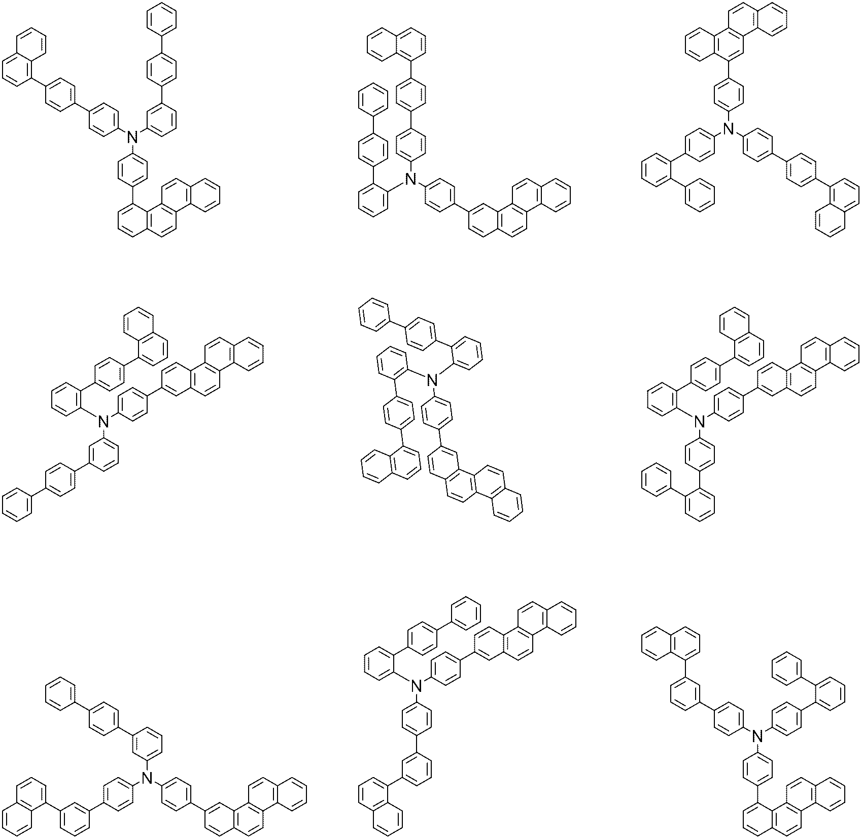


.
상기 화학식 1로 표시되는 화합물은 하기 반응식 1과 같은 제조 방법으로 제조할 수 있으며, 그 외 나머지 화합물도 유사하게 제조할 수 있다.
[반응식 1]

상기 반응식 1에서, Ar1, Ar2, L1, L2, R1, D, a, b 및 c는 상기 화학식 1에서 정의한 바와 같고, Y는 할로겐이고, 바람직하게는 Y는 브로모 또는 클로로이다.
상기 반응은 아민 치환 반응으로 팔라듐 촉매와 염기 존재 하에 수행하는 것이 바람직하며, 상기 반응을 위한 반응기는 당업계에 알려진 바에 따라 변경이 가능하다. 상기 제조 방법은 후술할 제조예에서 보다 구체화될 수 있다.
(유기 발광 소자)
또한, 본 발명은 상기 화학식 1로 표시되는 화합물을 포함하는 유기 발광 소자를 제공한다. 일례로, 본 발명은 제1 전극; 상기 제1 전극과 대향하여 구비된 제2 전극; 및 상기 제1 전극과 상기 제2 전극 사이에 구비된 1층 이상의 유기물 층을 포함하는 유기 발광 소자로서, 상기 유기물층 중 1층 이상은 상기 화학식 1로 표시되는 화합물을 포함하는, 유기 발광 소자를 제공한다.
본 발명의 유기 발광 소자의 유기물 층은 단층 구조로 이루어질 수도 있으나, 2층 이상의 유기물층이 적층된 다층 구조로 이루어질 수 있다. 예컨대, 본 발명의 유기 발광 소자는 유기물 층으로서 정공주입층, 정공수송층, 정공수송보조층, 발광층, 전자수송층, 전자주입층 등을 포함하는 구조를 가질 수 있다. 그러나 유기 발광 소자의 구조는 이에 한정되지 않고 더 적은 수의 유기층을 포함할 수 있다.
또한, 상기 유기물 층은 발광층을 포함할 수 있고, 이때 상기 화학식 1로 표시되는 화합물을 포함하는 유기물층은 발광층일 수 있다.
다른 구현예에서, 상기 유기물층은 정공주입층, 정공수송층, 정공수송보조층, 발광층, 정공저지층 및 전자주입 및 수송층을 포함할 수 있고, 이때 상기 화합물을 포함하는 유기물층은 발광층일 수 있다.
또한, 본 발명에 따른 유기 발광 소자는, 기판 상에 양극, 1층 이상의 유기물층 및 음극이 순차적으로 적층된 구조(normal type)의 유기 발광 소자일 수 있다. 또한, 본 발명에 따른 유기 발광 소자는 기판 상에 음극, 1층 이상의 유기물층 및 양극이 순차적으로 적층된 역방향 구조(inverted type)의 유기 발광 소자일 수 있다. 예컨대, 본 발명의 일실시예에 따른 유기 발광 소자의 구조는 도 1 및 2에 예시되어 있다.
도 1은 기판(1), 양극(2), 발광층(3), 음극(4)으로 이루어진 유기 발광 소자의 예를 도시한 것이다. 이와 같은 구조에 있어서, 상기 화학식 1로 표시되는 화합물은 상기 발광층에 포함될 수 있다.
도 2는 기판(1), 양극(2), 정공주입층(5), 정공수송층(6), 정공수송보조층(7), 발광층(3), 정공저지층(8), 전자주입 및 수송층(9) 및 음극(4)로 이루어진 유기 발광 소자의 예를 도시한 것이다. 이와 같은 구조에 있어서, 상기 화학식 1로 표시되는 화합물은 상기 정공수송보조층에 포함될 수 있다.
본 발명에 따른 유기 발광 소자는, 상기 유기물 층 중 1층 이상이 상기 화학식 1로 표시되는 화합물을 포함하는 것을 제외하고는 당 기술분야에 알려져 있는 재료와 방법으로 제조될 수 있다. 또한, 상기 유기 발광 소자가 복수개의 유기물층을 포함하는 경우, 상기 유기물층은 동일한 물질 또는 다른 물질로 형성될 수 있다.
예컨대, 본 발명에 따른 유기 발광 소자는 기판 상에 제1 전극, 유기물층 및 제2 전극을 순차적으로 적층시켜 제조할 수 있다. 이때, 스퍼터링법(sputtering)이나 전자빔 증발법(e-beam evaporation)과 같은 PVD(physical Vapor Deposition)방법을 이용하여, 기판 상에 금속 또는 전도성을 가지는 금속 산화물 또는 이들의 합금을 증착시켜 양극을 형성하고, 그 위에 정공 주입층, 정공 수송층, 발광층 및 전자 수송층을 포함하는 유기물 층을 형성한 후, 그 위에 음극으로 사용할 수 있는 물질을 증착시켜 제조할 수 있다. 이와 같은 방법 외에도, 기판 상에 음극 물질부터 유기물층, 양극 물질을 차례로 증착시켜 유기 발광 소자를 만들 수 있다.
또한, 상기 화학식 1로 표시되는 화합물은 유기 발광 소자의 제조시 진공 증착법 뿐만 아니라 용액 도포법에 의하여 유기물 층으로 형성될 수 있다. 여기서, 용액 도포법이라 함은 스핀 코팅, 딥코팅, 닥터 블레이딩, 잉크젯 프린팅, 스크린 프린팅, 스프레이법, 롤 코팅 등을 의미하지만, 이들만으로 한정되는 것은 아니다.
이와 같은 방법 외에도, 기판 상에 음극 물질로부터 유기물층, 양극 물질을 차례로 증착시켜 유기 발광 소자를 제조할 수 있다(WO 2003/012890). 다만, 제조 방법이 이에 한정되는 것은 아니다.
일례로, 상기 제1 전극은 양극이고, 상기 제2 전극은 음극이거나, 또는 상기 제1 전극은 음극이고, 상기 제2 전극은 양극이다.
상기 양극 물질로는 통상 유기물 층으로 정공 주입이 원활할 수 있도록 일함수가 큰 물질이 바람직하다. 상기 양극 물질의 구체적인 예로는 바나듐, 크롬, 구리, 아연, 금과 같은 금속 또는 이들의 합금; 아연 산화물, 인듐 산화물, 인듐주석 산화물(ITO), 인듐아연 산화물(IZO)과 같은 금속 산화물; ZnO:Al 또는 SnO2:Sb와 같은 금속과 산화물의 조합; 폴리(3-메틸티오펜), 폴리[3,4-(에틸렌-1,2-디옥시)티오펜](PEDOT), 폴리피롤 및 폴리아닐린과 같은 전도성 고분자 등이 있으나, 이들에만 한정되는 것은 아니다.
상기 음극 물질로는 통상 유기물층으로 전자 주입이 용이하도록 일함수가 작은 물질인 것이 바람직하다. 상기 음극 물질의 구체적인 예로는 마그네슘, 칼슘, 나트륨, 칼륨, 티타늄, 인듐, 이트륨, 리튬, 가돌리늄, 알루미늄, 은, 주석 및 납과 같은 금속 또는 이들의 합금; LiF/Al 또는 LiO2/Al과 같은 다층 구조 물질 등이 있으나, 이들에만 한정되는 것은 아니다.
상기 정공주입층은 전극으로부터 정공을 주입하는 층으로, 정공 주입 물질로는 정공을 수송하는 능력을 가져 양극에서의 정공 주입효과, 발광층 또는 발광재료에 대하여 우수한 정공 주입 효과를 갖고, 발광층에서 생성된 여기자의 전자주입층 또는 전자주입재료에의 이동을 방지하며, 또한, 박막 형성 능력이 우수한 화합물이 바람직하다. 정공 주입 물질의 HOMO(highest occupied molecular orbital)가 양극 물질의 일함수와 주변 유기물 층의 HOMO 사이인 것이 바람직하다. 정공 주입 물질의 구체적인 예로는 금속 포피린(porphyrin), 올리고티오펜, 아릴아민 계열의 유기물, 헥사니트릴헥사아자트리페닐렌 계열의 유기물, 퀴나크리돈(quinacridone)계열의 유기물, 페릴렌(perylene) 계열의 유기물, 안트라퀴논 및 폴리아닐린과 폴리티오펜 계열의 전도성 고분자 등이 있으나, 이들에만 한정되는 것은 아니다.
상기 정공수송층은 정공주입층으로부터 정공을 수취하여 발광층까지 정공을 수송하는 층으로, 정공 수송 물질로 양극이나 정공 주입층으로부터 정공을 수송받아 발광층으로 옮겨줄 수 있는 물질로 정공에 대한 이동성이 큰 물질이 적합하다. 구체적인 예로는 아릴아민 계열의 유기물, 전도성 고분자, 및 공액 부분과 비공액 부분이 함께 있는 블록 공중합체 등이 있으나, 이들에만 한정되는 것은 아니다.
한편, 전자차단층은 상기 정공수송층 상에 형성되어, 바람직하게는 발광층에 접하여 구비되어, 정공이동도를 조절하고, 전자의 과다한 이동을 방지하여 정공-전자간 결합 확률을 높여줌으로써 유기 발광 소자의 효율을 개선하는 역할을 하는 층을 의미한다. 상기 전자차단층은 전자저지물질을 포함하고, 이러한 전자저지물질의 예로 아릴아민 계열의 유기물 등을 사용할 수 있으나, 이에 한정되는 것은 아니다.
상기 정공수송보조층은 정공수송층과 발광층 사이에 위치한 층이다. 상기 정공수송보조층을 포함함으로써, 정공수송층으로부터 발광층으로 정공이 보다 원활하게 수송되면서 엑시톤이 발광층 내에 가두어져 발광 누수가 방지되어, 유기 발광 소자가 우수한 발광 효율을 갖는 효과가 있다. 바람직하게는, 상기 화학식 1로 표시되는 화합물이 정공수송보조 재료로 사용될 수 있다.
상기 발광 물질로는 정공수송층과 전자수송층으로부터 정공과 전자를 각각 수송 받아 결합시킴으로써 가시광선 영역의 빛을 낼 수 있는 물질로서, 형광이나 인광에 대한 양자 효율이 좋은 물질이 바람직하다. 구체적인 예로 8-히드록시-퀴놀린 알루미늄 착물(Alq3); 카르바졸 계열 화합물; 이량체화 스티릴(dimerized styryl) 화합물; BAlq; 10-히드록시벤조 퀴놀린-금속 화합물; 벤족사졸, 벤즈티아졸 및 벤즈이미다졸 계열의 화합물; 폴리(p-페닐렌비닐렌)(PPV) 계열의 고분자; 스피로(spiro) 화합물; 폴리플루오렌, 루브렌 등이 있으나, 이들에만 한정되는 것은 아니다.
상기 발광층은 호스트 재료 및 도펀트 재료를 포함할 수 있다. 호스트 재료는 축합 방향족환 유도체 또는 헤테로환 함유 화합물 등이 있다. 구체적으로 축합 방향족환 유도체로는 안트라센 유도체, 피렌 유도체, 나프탈렌 유도체, 펜타센 유도체, 페난트렌 화합물, 플루오란텐 화합물 등이 있고, 헤테로환 함유 화합물로는 카바졸 유도체, 디벤조퓨란 유도체, 래더형 퓨란 화합물, 피리미딘 유도체 등이 있으나, 이에 한정되지 않는다.
도펀트 재료로는 방향족 아민 유도체, 스트릴아민 화합물, 붕소 착체, 플루오란텐 화합물, 금속 착체 등이 있다. 구체적으로 방향족 아민 유도체로는 치환 또는 비치환된 아릴아미노기를 갖는 축합 방향족환 유도체로서, 아릴아미노기를 갖는 피렌, 안트라센, 크리센, 페리플란텐 등이 있으며, 스티릴아민 화합물로는 치환 또는 비치환된 아릴아민에 적어도 1개의 아릴비닐기가 치환되어 있는 화합물로, 아릴기, 실릴기, 알킬기, 사이클로알킬기 및 아릴아미노기로 이루어진 군에서 1 또는 2 이상 선택되는 치환기가 치환 또는 비치환된다. 구체적으로 스티릴아민, 스티릴디아민, 스티릴트리아민, 스티릴테트라아민 등이 있으나, 이에 한정되지 않는다. 또한, 금속 착체로는 이리듐 착체, 백금 착체 등이 있으나, 이에 한정되지 않는다.
상기 정공저지층은 발광층 상에 형성되어, 바람직하게는 발광층에 접하여 구비되어, 전자이동도를 조절하고 정공의 과다한 이동을 방지하여 정공-전자간 결합 확률을 높여줌으로써 유기 발광 소자의 효율을 개선하는 역할을 하는 층을 의미한다. 상기 정공저지층은 정공저지물질을 포함하고, 이러한 정공저지물질의 예로 트리아진을 포함한 아진류유도체; 트리아졸 유도체; 옥사디아졸 유도체; 페난트롤린 유도체; 포스핀옥사이드 유도체 등의 전자흡인기가 도입된 화합물을 사용할 수 있으나, 이에 한정되는 것은 아니다.
상기 전자 주입 및 수송층은 전극으로부터 전자를 주입하고, 수취된 전자를 발광층까지 수송하는 전자수송층 및 전자주입층의 역할을 동시에 수행하는 층으로, 상기 발광층 또는 상기 정공저지층 상에 형성된다. 이러한 전자 주입 및 수송물질로는 음극으로부터 전자를 잘 주입 받아 발광층으로 옮겨줄 수 있는 물질로서, 전자에 대한 이동성이 큰 물질이 적합하다. 이러한 전자 주입 및 수송층 물질로 상기 화학식 1로 표시되는 화합물을 사용할 수 있다. 추가적인 전자 주입 및 수송물질의 예로는 8-히드록시퀴놀린의 Al 착물; Alq3를 포함한 착물; 유기 라디칼 화합물; 히드록시플라본-금속 착물; 트리아진 유도체 등이 있으나, 이에 한정되는 것은 아니다. 또는 플루오레논, 안트라퀴노다이메탄, 다이페노퀴논, 티오피란 다이옥사이드, 옥사졸, 옥사다이아졸, 트리아졸, 이미다졸, 페릴렌테트라카복실산, 플루오레닐리덴 메탄, 안트론 등과 그들의 유도체, 금속 착체 화합물, 또는 질소 함유 5원환 유도체 등과 함께 사용할 수도 있으나, 이에 한정되는 것은 아니다.
상기 전자 주입 및 수송층은 전자주입층 및 전자수송층과 같은 별개의 층으로도 형성될 수 있다. 이와 같은 경우, 전자 수송층은 상기 발광층 또는 상기 정공저지층 상에 형성되고, 상기 전자 수송층에 포함되는 전자 수송 물질로는 상술한 전자 주입 및 수송 물질이 사용될 수 있다. 또한, 전자 주입층은 상기 전자 수송층 상에 형성되고, 상기 전자 주입층에 포함되는 전자 주입 물질로는 LiF, NaCl, CsF, Li2O, BaO, 플루오레논, 안트라퀴노다이메탄, 다이페노퀴논, 티오피란 다이옥사이드, 옥사졸, 옥사다이아졸, 트리아졸, 이미다졸, 페릴렌테트라카복실산, 플루오레닐리덴 메탄, 안트론 등과 그들의 유도체, 금속 착체 화합물 및 질소 함유 5원환 유도체 등이 사용될 수 있다.
상기 금속 착체 화합물로서는 8-하이드록시퀴놀리나토 리튬, 비스(8-하이드록시퀴놀리나토)아연, 비스(8-하이드록시퀴놀리나토)구리, 비스(8-하이드록시퀴놀리나토)망간, 트리스(8-하이드록시퀴놀리나토)알루미늄, 트리스(2-메틸-8-하이드록시퀴놀리나토)알루미늄, 트리스(8-하이드록시퀴놀리나토)갈륨, 비스(10-하이드록시벤조[h]퀴놀리나토)베릴륨, 비스(10-하이드록시벤조[h]퀴놀리나토)아연, 비스(2-메틸-8-하이드록시퀴놀리나토)클로로갈륨, 비스(2-메틸-8-하이드록시퀴놀리나토)(o-크레졸라토)갈륨, 비스(2-메틸-8-하이드록시퀴놀리나토)(1-나프톨라토)알루미늄, 비스(2-메틸-8-하이드록시퀴놀리나토)(2-나프톨라토)갈륨 등이 있으나, 이에 한정되는 것은 아니다.
본 발명에 따른 유기 발광 소자는 배면 발광(bottom emission) 소자, 전면 발광(top emission) 소자, 또는 양면 발광 소자일 수 있으며, 특히 상대적으로 높은 발광 효율이 요구되는 배면 발광 소자일 수 있다.
또한, 본 발명에 따른 화합물은 유기 발광 소자 외에도 유기 태양 전지 또는 유기 트랜지스터에 포함될 수 있다.
상기 화학식 1로 표시되는 화합물 및 이를 포함하는 유기 발광 소자의 제조는 이하 실시예에서 구체적으로 설명한다. 그러나 하기 실시예는 본 발명을 예시하기 위한 것이며, 본 발명의 범위가 이들에 의하여 한정되는 것은 아니다.
[실시예]
합성예 1

질소 분위기에서 sub1 (15 g, 57.1mmol), amine1 (22.3g, 59.9 mmol), sodium tert-butoxide (8.2 g, 85.6 mmol)을 Xylene 300ml에 넣고 교반 및 환류했다. 이 후 bis(tri-tert-butylphosphine)palladium(0) (0.3 g, 0.6 mmol)을 투입했다. 5시간 후 반응이 종결되어서 상온으로 식히고 감압하여 용매를 제거했다. 이 후 화합물을 다시 클로로포름에 완전히 녹이고 물로 2회 세척 후에 유기층을 분리하여 무수황산마그네슘 처리 후 여과하여 여액을 감압 증류했다. 농축한 화합물을 실리카 겔 컬럼 크로마토그래피로 정제해서 화합물 1 19.5g을 얻었다. (수율 57%, MS: [M+H]+= 599)
합성예 2

질소 분위기에서 sub1 (15 g, 57.1mmol), amine2 (28.6g, 59.9 mmol), sodium tert-butoxide (8.2 g, 85.6 mmol)을 Xylene 300ml에 넣고 교반 및 환류했다. 이 후 bis(tri-tert-butylphosphine)palladium(0) (0.3 g, 0.6 mmol)을 투입했다. 5시간 후 반응이 종결되어서 상온으로 식히고 감압하여 용매를 제거했다. 이 후 화합물을 다시 클로로포름에 완전히 녹이고 물로 2회 세척 후에 유기층을 분리하여 무수황산마그네슘 처리 후 여과하여 여액을 감압 증류했다. 농축한 화합물을 실리카 겔 컬럼 크로마토그래피로 정제해서 화합물 2 24.1g을 얻었다. (수율 60%, MS: [M+H]+= 705)
합성예 3

질소 분위기에서 sub1 (15 g, 57.1mmol), amine3 (32.2g, 59.9 mmol), sodium tert-butoxide (8.2 g, 85.6 mmol)을 Xylene 300ml에 넣고 교반 및 환류했다. 이 후 bis(tri-tert-butylphosphine)palladium(0) (0.3 g, 0.6 mmol)을 투입했다. 5시간 후 반응이 종결되어서 상온으로 식히고 감압하여 용매를 제거했다. 이 후 화합물을 다시 클로로포름에 완전히 녹이고 물로 2회 세척 후에 유기층을 분리하여 무수황산마그네슘 처리 후 여과하여 여액을 감압 증류했다. 농축한 화합물을 실리카 겔 컬럼 크로마토그래피로 정제해서 화합물 3 26.2g을 얻었다. (수율 60%, MS: [M+H]+= 765)
합성예 4

질소 분위기에서 sub1 (15 g, 57.1mmol), amine4 (28.3g, 59.9 mmol), sodium tert-butoxide (8.2 g, 85.6 mmol)을 Xylene 300ml에 넣고 교반 및 환류했다. 이 후 bis(tri-tert-butylphosphine)palladium(0) (0.3 g, 0.6 mmol)을 투입했다. 5시간 후 반응이 종결되어서 상온으로 식히고 감압하여 용매를 제거했다. 이 후 화합물을 다시 클로로포름에 완전히 녹이고 물로 2회 세척 후에 유기층을 분리하여 무수황산마그네슘 처리 후 여과하여 여액을 감압 증류했다. 농축한 화합물을 실리카 겔 컬럼 크로마토그래피로 정제해서 화합물 4 20.7g을 얻었다. (수율 52%, MS: [M+H]+= 699)
합성예 5

질소 분위기에서 sub1 (15 g, 57.1mmol), amine5 (28.6g, 59.9 mmol), sodium tert-butoxide (8.2 g, 85.6 mmol)을 Xylene 300ml에 넣고 교반 및 환류했다. 이 후 bis(tri-tert-butylphosphine)palladium(0) (0.3 g, 0.6 mmol)을 투입했다. 5시간 후 반응이 종결되어서 상온으로 식히고 감압하여 용매를 제거했다. 이 후 화합물을 다시 클로로포름에 완전히 녹이고 물로 2회 세척 후에 유기층을 분리하여 무수황산마그네슘 처리 후 여과하여 여액을 감압 증류했다. 농축한 화합물을 실리카 겔 컬럼 크로마토그래피로 정제해서 화합물 5 26.1g을 얻었다. (수율 65%, MS: [M+H]+= 705)
합성예 6

질소 분위기에서 sub1 (15 g, 57.1mmol), amine6 (26.8g, 59.9 mmol), sodium tert-butoxide (8.2 g, 85.6 mmol)을 Xylene 300ml에 넣고 교반 및 환류했다. 이 후 bis(tri-tert-butylphosphine)palladium(0) (0.3 g, 0.6 mmol)을 투입했다. 5시간 후 반응이 종결되어서 상온으로 식히고 감압하여 용매를 제거했다. 이 후 화합물을 다시 클로로포름에 완전히 녹이고 물로 2회 세척 후에 유기층을 분리하여 무수황산마그네슘 처리 후 여과하여 여액을 감압 증류했다. 농축한 화합물을 실리카 겔 컬럼 크로마토그래피로 정제해서 화합물 6 19.6g을 얻었다. (수율 51%, MS: [M+H]+= 675)
합성예 7

질소 분위기에서 sub2 (15 g, 44.3mmol), amine7 (21.5g, 46.5 mmol), sodium tert-butoxide (6.4 g, 66.4 mmol)을 Xylene 300ml에 넣고 교반 및 환류했다. 이 후 bis(tri-tert-butylphosphine)palladium(0) (0.2 g, 0.4 mmol)을 투입했다. 5시간 후 반응이 종결되어서 상온으로 식히고 감압하여 용매를 제거했다. 이 후 화합물을 다시 클로로포름에 완전히 녹이고 물로 2회 세척 후에 유기층을 분리하여 무수황산마그네슘 처리 후 여과하여 여액을 감압 증류했다. 농축한 화합물을 실리카 겔 컬럼 크로마토그래피로 정제해서 화합물 7 19.6g을 얻었다. (수율 58%, MS: [M+H]+= 765)
합성예 8

질소 분위기에서 sub2 (15 g, 44.3mmol), amine8 (17.3g, 46.5 mmol), sodium tert-butoxide (6.4 g, 66.4 mmol)을 Xylene 300ml에 넣고 교반 및 환류했다. 이 후 bis(tri-tert-butylphosphine)palladium(0) (0.2 g, 0.4 mmol)을 투입했다. 5시간 후 반응이 종결되어서 상온으로 식히고 감압하여 용매를 제거했다. 이 후 화합물을 다시 클로로포름에 완전히 녹이고 물로 2회 세척 후에 유기층을 분리하여 무수황산마그네슘 처리 후 여과하여 여액을 감압 증류했다. 농축한 화합물을 실리카 겔 컬럼 크로마토그래피로 정제해서 화합물 8 18.5g을 얻었다. (수율 62%, MS: [M+H]+= 675)
합성예 9

질소 분위기에서 sub2 (15 g, 44.3mmol), amine9 (20.8g, 46.5 mmol), sodium tert-butoxide (6.4 g, 66.4 mmol)을 Xylene 300ml에 넣고 교반 및 환류했다. 이 후 bis(tri-tert-butylphosphine)palladium(0) (0.2 g, 0.4 mmol)을 투입했다. 5시간 후 반응이 종결되어서 상온으로 식히고 감압하여 용매를 제거했다. 이 후 화합물을 다시 클로로포름에 완전히 녹이고 물로 2회 세척 후에 유기층을 분리하여 무수황산마그네슘 처리 후 여과하여 여액을 감압 증류했다. 농축한 화합물을 실리카 겔 컬럼 크로마토그래피로 정제해서 화합물 9 17.3g을 얻었다. (수율 52%, MS: [M+H]+= 751)
합성예 10

질소 분위기에서 sub2 (15 g, 44.3mmol), amine10 (21.9g, 46.5 mmol), sodium tert-butoxide (6.4 g, 66.4 mmol)을 Xylene 300ml에 넣고 교반 및 환류했다. 이 후 bis(tri-tert-butylphosphine)palladium(0) (0.2 g, 0.4 mmol)을 투입했다. 5시간 후 반응이 종결되어서 상온으로 식히고 감압하여 용매를 제거했다. 이 후 화합물을 다시 클로로포름에 완전히 녹이고 물로 2회 세척 후에 유기층을 분리하여 무수황산마그네슘 처리 후 여과하여 여액을 감압 증류했다. 농축한 화합물을 실리카 겔 컬럼 크로마토그래피로 정제해서 화합물 10 18.2g을 얻었다. (수율 53%, MS: [M+H]+= 775)
합성예 11

질소 분위기에서 sub3 (15 g, 57.1mmol), amine11 (26.8g, 59.9 mmol), sodium tert-butoxide (8.2 g, 85.6 mmol)을 Xylene 300ml에 넣고 교반 및 환류했다. 이 후 bis(tri-tert-butylphosphine)palladium(0) (0.3 g, 0.6 mmol)을 투입했다. 5시간 후 반응이 종결되어서 상온으로 식히고 감압하여 용매를 제거했다. 이 후 화합물을 다시 클로로포름에 완전히 녹이고 물로 2회 세척 후에 유기층을 분리하여 무수황산마그네슘 처리 후 여과하여 여액을 감압 증류했다. 농축한 화합물을 실리카 겔 컬럼 크로마토그래피로 정제해서 화합물 11 21.5g을 얻었다. (수율 56%, MS: [M+H]+= 675)
합성예 12

질소 분위기에서 sub3 (15 g, 57.1mmol), amine12 (25.3g, 59.9 mmol), sodium tert-butoxide (8.2 g, 85.6 mmol)을 Xylene 300ml에 넣고 교반 및 환류했다. 이 후 bis(tri-tert-butylphosphine)palladium(0) (0.3 g, 0.6 mmol)을 투입했다. 5시간 후 반응이 종결되어서 상온으로 식히고 감압하여 용매를 제거했다. 이 후 화합물을 다시 클로로포름에 완전히 녹이고 물로 2회 세척 후에 유기층을 분리하여 무수황산마그네슘 처리 후 여과하여 여액을 감압 증류했다. 농축한 화합물을 실리카 겔 컬럼 크로마토그래피로 정제해서 화합물 12 24.4g을 얻었다. (수율 66%, MS: [M+H]+= 649)
합성예 13

질소 분위기에서 sub3 (15 g, 57.1mmol), amine13 (27.7g, 59.9 mmol), sodium tert-butoxide (8.2 g, 85.6 mmol)을 Xylene 300ml에 넣고 교반 및 환류했다. 이 후 bis(tri-tert-butylphosphine)palladium(0) (0.3 g, 0.6 mmol)을 투입했다. 5시간 후 반응이 종결되어서 상온으로 식히고 감압하여 용매를 제거했다. 이 후 화합물을 다시 클로로포름에 완전히 녹이고 물로 2회 세척 후에 유기층을 분리하여 무수황산마그네슘 처리 후 여과하여 여액을 감압 증류했다. 농축한 화합물을 실리카 겔 컬럼 크로마토그래피로 정제해서 화합물 13 25.9g을 얻었다. (수율 66%, MS: [M+H]+= 689)
합성예 14

질소 분위기에서 sub3 (15 g, 57.1mmol), amine14 (28.3g, 59.9 mmol), sodium tert-butoxide (8.2 g, 85.6 mmol)을 Xylene 300ml에 넣고 교반 및 환류했다. 이 후 bis(tri-tert-butylphosphine)palladium(0) (0.3 g, 0.6 mmol)을 투입했다. 5시간 후 반응이 종결되어서 상온으로 식히고 감압하여 용매를 제거했다. 이 후 화합물을 다시 클로로포름에 완전히 녹이고 물로 2회 세척 후에 유기층을 분리하여 무수황산마그네슘 처리 후 여과하여 여액을 감압 증류했다. 농축한 화합물을 실리카 겔 컬럼 크로마토그래피로 정제해서 화합물 14 27.5g을 얻었다. (수율 69%, MS: [M+H]+= 699)
합성예 15

질소 분위기에서 sub4 (15 g, 44.3mmol), amine15 (21.9g, 46.5 mmol), sodium tert-butoxide (6.4 g, 66.4 mmol)을 Xylene 300ml에 넣고 교반 및 환류했다. 이 후 bis(tri-tert-butylphosphine)palladium(0) (0.2 g, 0.4 mmol)을 투입했다. 5시간 후 반응이 종결되어서 상온으로 식히고 감압하여 용매를 제거했다. 이 후 화합물을 다시 클로로포름에 완전히 녹이고 물로 2회 세척 후에 유기층을 분리하여 무수황산마그네슘 처리 후 여과하여 여액을 감압 증류했다. 농축한 화합물을 실리카 겔 컬럼 크로마토그래피로 정제해서 화합물 15 19.5g을 얻었다. (수율 57%, MS: [M+H]+= 775)
합성예 16

질소 분위기에서 sub4 (15 g, 44.3mmol), amine16 (17.3g, 46.5 mmol), sodium tert-butoxide (6.4 g, 66.4 mmol)을 Xylene 300ml에 넣고 교반 및 환류했다. 이 후 bis(tri-tert-butylphosphine)palladium(0) (0.2 g, 0.4 mmol)을 투입했다. 5시간 후 반응이 종결되어서 상온으로 식히고 감압하여 용매를 제거했다. 이 후 화합물을 다시 클로로포름에 완전히 녹이고 물로 2회 세척 후에 유기층을 분리하여 무수황산마그네슘 처리 후 여과하여 여액을 감압 증류했다. 농축한 화합물을 실리카 겔 컬럼 크로마토그래피로 정제해서 화합물 16 19.1g을 얻었다. (수율 64%, MS: [M+H]+= 675)
합성예 17

질소 분위기에서 sub4 (15 g, 44.3mmol), amine17 (17.3g, 46.5 mmol), sodium tert-butoxide (6.4 g, 66.4 mmol)을 Xylene 300ml에 넣고 교반 및 환류했다. 이 후 bis(tri-tert-butylphosphine)palladium(0) (0.2 g, 0.4 mmol)을 투입했다. 5시간 후 반응이 종결되어서 상온으로 식히고 감압하여 용매를 제거했다. 이 후 화합물을 다시 클로로포름에 완전히 녹이고 물로 2회 세척 후에 유기층을 분리하여 무수황산마그네슘 처리 후 여과하여 여액을 감압 증류했다. 농축한 화합물을 실리카 겔 컬럼 크로마토그래피로 정제해서 화합물 17 18.8g을 얻었다. (수율 63%, MS: [M+H]+= 675)
합성예 18

질소 분위기에서 sub4 (15 g, 44.3mmol), amine18 (24.3g, 46.5 mmol), sodium tert-butoxide (6.4 g, 66.4 mmol)을 Xylene 300ml에 넣고 교반 및 환류했다. 이 후 bis(tri-tert-butylphosphine)palladium(0) (0.2 g, 0.4 mmol)을 투입했다. 5시간 후 반응이 종결되어서 상온으로 식히고 감압하여 용매를 제거했다. 이 후 화합물을 다시 클로로포름에 완전히 녹이고 물로 2회 세척 후에 유기층을 분리하여 무수황산마그네슘 처리 후 여과하여 여액을 감압 증류했다. 농축한 화합물을 실리카 겔 컬럼 크로마토그래피로 정제해서 화합물 18 21.9g을 얻었다. (수율 60%, MS: [M+H]+= 827)
합성예 19

질소 분위기에서 sub4 (15 g, 44.3mmol), amine19 (23.1g, 46.5 mmol), sodium tert-butoxide (6.4 g, 66.4 mmol)을 Xylene 300ml에 넣고 교반 및 환류했다. 이 후 bis(tri-tert-butylphosphine)palladium(0) (0.2 g, 0.4 mmol)을 투입했다. 5시간 후 반응이 종결되어서 상온으로 식히고 감압하여 용매를 제거했다. 이 후 화합물을 다시 클로로포름에 완전히 녹이고 물로 2회 세척 후에 유기층을 분리하여 무수황산마그네슘 처리 후 여과하여 여액을 감압 증류했다. 농축한 화합물을 실리카 겔 컬럼 크로마토그래피로 정제해서 화합물 19 20.9g을 얻었다. (수율 59%, MS: [M+H]+= 801)
합성예 20

질소 분위기에서 sub5 (15 g, 57.1mmol), amine20 (22.3g, 59.9 mmol), sodium tert-butoxide (8.2 g, 85.6 mmol)을 Xylene 300ml에 넣고 교반 및 환류했다. 이 후 bis(tri-tert-butylphosphine)palladium(0) (0.3 g, 0.6 mmol)을 투입했다. 5시간 후 반응이 종결되어서 상온으로 식히고 감압하여 용매를 제거했다. 이 후 화합물을 다시 클로로포름에 완전히 녹이고 물로 2회 세척 후에 유기층을 분리하여 무수황산마그네슘 처리 후 여과하여 여액을 감압 증류했다. 농축한 화합물을 실리카 겔 컬럼 크로마토그래피로 정제해서 화합물 20 18.1g을 얻었다. (수율 53%, MS: [M+H]+= 599)
합성예 21

질소 분위기에서 sub5 (15 g, 57.1mmol), amine21 (22.3g, 59.9 mmol), sodium tert-butoxide (8.2 g, 85.6 mmol)을 Xylene 300ml에 넣고 교반 및 환류했다. 이 후 bis(tri-tert-butylphosphine)palladium(0) (0.3 g, 0.6 mmol)을 투입했다. 5시간 후 반응이 종결되어서 상온으로 식히고 감압하여 용매를 제거했다. 이 후 화합물을 다시 클로로포름에 완전히 녹이고 물로 2회 세척 후에 유기층을 분리하여 무수황산마그네슘 처리 후 여과하여 여액을 감압 증류했다. 농축한 화합물을 실리카 겔 컬럼 크로마토그래피로 정제해서 화합물 21 21.5g을 얻었다. (수율 63%, MS: [M+H]+= 599)
합성예 22

질소 분위기에서 sub5 (15 g, 57.1mmol), amine22 (27.7g, 59.9 mmol), sodium tert-butoxide (8.2 g, 85.6 mmol)을 Xylene 300ml에 넣고 교반 및 환류했다. 이 후 bis(tri-tert-butylphosphine)palladium(0) (0.3 g, 0.6 mmol)을 투입했다. 5시간 후 반응이 종결되어서 상온으로 식히고 감압하여 용매를 제거했다. 이 후 화합물을 다시 클로로포름에 완전히 녹이고 물로 2회 세척 후에 유기층을 분리하여 무수황산마그네슘 처리 후 여과하여 여액을 감압 증류했다. 농축한 화합물을 실리카 겔 컬럼 크로마토그래피로 정제해서 화합물 22 22.4g을 얻었다. (수율 57%, MS: [M+H]+= 689)
합성예 23

질소 분위기에서 sub5 (15 g, 57.1mmol), amine23 (32.2g, 59.9 mmol), sodium tert-butoxide (8.2 g, 85.6 mmol)을 Xylene 300ml에 넣고 교반 및 환류했다. 이 후 bis(tri-tert-butylphosphine)palladium(0) (0.3 g, 0.6 mmol)을 투입했다. 5시간 후 반응이 종결되어서 상온으로 식히고 감압하여 용매를 제거했다. 이 후 화합물을 다시 클로로포름에 완전히 녹이고 물로 2회 세척 후에 유기층을 분리하여 무수황산마그네슘 처리 후 여과하여 여액을 감압 증류했다. 농축한 화합물을 실리카 겔 컬럼 크로마토그래피로 정제해서 화합물 23 25.3g을 얻었다. (수율 58%, MS: [M+H]+= 765)
합성예 24

질소 분위기에서 sub5 (15 g, 57.1mmol), amine24 (31.4g, 59.9 mmol), sodium tert-butoxide (8.2 g, 85.6 mmol)을 Xylene 300ml에 넣고 교반 및 환류했다. 이 후 bis(tri-tert-butylphosphine)palladium(0) (0.3 g, 0.6 mmol)을 투입했다. 5시간 후 반응이 종결되어서 상온으로 식히고 감압하여 용매를 제거했다. 이 후 화합물을 다시 클로로포름에 완전히 녹이고 물로 2회 세척 후에 유기층을 분리하여 무수황산마그네슘 처리 후 여과하여 여액을 감압 증류했다. 농축한 화합물을 실리카 겔 컬럼 크로마토그래피로 정제해서 화합물 24 24.4g을 얻었다. (수율 57%, MS: [M+H]+= 751)
합성예 25

질소 분위기에서 sub5 (15 g, 57.1mmol), amine25 (31.4g, 59.9 mmol), sodium tert-butoxide (8.2 g, 85.6 mmol)을 Xylene 300ml에 넣고 교반 및 환류했다. 이 후 bis(tri-tert-butylphosphine)palladium(0) (0.3 g, 0.6 mmol)을 투입했다. 5시간 후 반응이 종결되어서 상온으로 식히고 감압하여 용매를 제거했다. 이 후 화합물을 다시 클로로포름에 완전히 녹이고 물로 2회 세척 후에 유기층을 분리하여 무수황산마그네슘 처리 후 여과하여 여액을 감압 증류했다. 농축한 화합물을 실리카 겔 컬럼 크로마토그래피로 정제해서 화합물 25 28.7g을 얻었다. (수율 67%, MS: [M+H]+= 751)
합성예 26

질소 분위기에서 sub5 (15 g, 57.1mmol), amine26 (26.8g, 59.9 mmol), sodium tert-butoxide (8.2 g, 85.6 mmol)을 Xylene 300ml에 넣고 교반 및 환류했다. 이 후 bis(tri-tert-butylphosphine)palladium(0) (0.3 g, 0.6 mmol)을 투입했다. 5시간 후 반응이 종결되어서 상온으로 식히고 감압하여 용매를 제거했다. 이 후 화합물을 다시 클로로포름에 완전히 녹이고 물로 2회 세척 후에 유기층을 분리하여 무수황산마그네슘 처리 후 여과하여 여액을 감압 증류했다. 농축한 화합물을 실리카 겔 컬럼 크로마토그래피로 정제해서 화합물 26 20.4g을 얻었다. (수율 53%, MS: [M+H]+= 675)
합성예 27

질소 분위기에서 sub6 (15 g, 44.3mmol), amine27 (19.6g, 46.5 mmol), sodium tert-butoxide (6.4 g, 66.4 mmol)을 Xylene 300ml에 넣고 교반 및 환류했다. 이 후 bis(tri-tert-butylphosphine)palladium(0) (0.2 g, 0.4 mmol)을 투입했다. 5시간 후 반응이 종결되어서 상온으로 식히고 감압하여 용매를 제거했다. 이 후 화합물을 다시 클로로포름에 완전히 녹이고 물로 2회 세척 후에 유기층을 분리하여 무수황산마그네슘 처리 후 여과하여 여액을 감압 증류했다. 농축한 화합물을 실리카 겔 컬럼 크로마토그래피로 정제해서 화합물 27 16g을 얻었다. (수율 50%, MS: [M+H]+= 725)
합성예 28

질소 분위기에서 sub7 (15 g, 44.3mmol), amine28 (17.3g, 46.5 mmol), sodium tert-butoxide (6.4 g, 66.4 mmol)을 Xylene 300ml에 넣고 교반 및 환류했다. 이 후 bis(tri-tert-butylphosphine)palladium(0) (0.2 g, 0.4 mmol)을 투입했다. 5시간 후 반응이 종결되어서 상온으로 식히고 감압하여 용매를 제거했다. 이 후 화합물을 다시 클로로포름에 완전히 녹이고 물로 2회 세척 후에 유기층을 분리하여 무수황산마그네슘 처리 후 여과하여 여액을 감압 증류했다. 농축한 화합물을 실리카 겔 컬럼 크로마토그래피로 정제해서 화합물 28 20g을 얻었다. (수율 67%, MS: [M+H]+= 675)
합성예 29

질소 분위기에서 sub7 (15 g, 44.3mmol), amine29 (17.3g, 46.5 mmol), sodium tert-butoxide (6.4 g, 66.4 mmol)을 Xylene 300ml에 넣고 교반 및 환류했다. 이 후 bis(tri-tert-butylphosphine)palladium(0) (0.2 g, 0.4 mmol)을 투입했다. 5시간 후 반응이 종결되어서 상온으로 식히고 감압하여 용매를 제거했다. 이 후 화합물을 다시 클로로포름에 완전히 녹이고 물로 2회 세척 후에 유기층을 분리하여 무수황산마그네슘 처리 후 여과하여 여액을 감압 증류했다. 농축한 화합물을 실리카 겔 컬럼 크로마토그래피로 정제해서 화합물 29 20g을 얻었다. (수율 67%, MS: [M+H]+= 675)
합성예 30

질소 분위기에서 sub7 (15 g, 44.3mmol), amine30 (24.3g, 46.5 mmol), sodium tert-butoxide (6.4 g, 66.4 mmol)을 Xylene 300ml에 넣고 교반 및 환류했다. 이 후 bis(tri-tert-butylphosphine)palladium(0) (0.2 g, 0.4 mmol)을 투입했다. 5시간 후 반응이 종결되어서 상온으로 식히고 감압하여 용매를 제거했다. 이 후 화합물을 다시 클로로포름에 완전히 녹이고 물로 2회 세척 후에 유기층을 분리하여 무수황산마그네슘 처리 후 여과하여 여액을 감압 증류했다. 농축한 화합물을 실리카 겔 컬럼 크로마토그래피로 정제해서 화합물 30 22.3g을 얻었다. (수율 61%, MS: [M+H]+= 827)
합성예 31

질소 분위기에서 sub8 (15 g, 57.1mmol), amine31 (27.7g, 59.9 mmol), sodium tert-butoxide (8.2 g, 85.6 mmol)을 Xylene 300ml에 넣고 교반 및 환류했다. 이 후 bis(tri-tert-butylphosphine)palladium(0) (0.3 g, 0.6 mmol)을 투입했다. 5시간 후 반응이 종결되어서 상온으로 식히고 감압하여 용매를 제거했다. 이 후 화합물을 다시 클로로포름에 완전히 녹이고 물로 2회 세척 후에 유기층을 분리하여 무수황산마그네슘 처리 후 여과하여 여액을 감압 증류했다. 농축한 화합물을 실리카 겔 컬럼 크로마토그래피로 정제해서 화합물 31 21.6g을 얻었다. (수율 55%, MS: [M+H]+= 689)
합성예 32

질소 분위기에서 sub8 (15 g, 57.1mmol), amine32 (32.2g, 59.9 mmol), sodium tert-butoxide (8.2 g, 85.6 mmol)을 Xylene 300ml에 넣고 교반 및 환류했다. 이 후 bis(tri-tert-butylphosphine)palladium(0) (0.3 g, 0.6 mmol)을 투입했다. 5시간 후 반응이 종결되어서 상온으로 식히고 감압하여 용매를 제거했다. 이 후 화합물을 다시 클로로포름에 완전히 녹이고 물로 2회 세척 후에 유기층을 분리하여 무수황산마그네슘 처리 후 여과하여 여액을 감압 증류했다. 농축한 화합물을 실리카 겔 컬럼 크로마토그래피로 정제해서 화합물 32 25.3g을 얻었다. (수율 58%, MS: [M+H]+= 765)
합성예 33

질소 분위기에서 sub8 (15 g, 57.1mmol), amine33 (32.8g, 59.9 mmol), sodium tert-butoxide (8.2 g, 85.6 mmol)을 Xylene 300ml에 넣고 교반 및 환류했다. 이 후 bis(tri-tert-butylphosphine)palladium(0) (0.3 g, 0.6 mmol)을 투입했다. 5시간 후 반응이 종결되어서 상온으로 식히고 감압하여 용매를 제거했다. 이 후 화합물을 다시 클로로포름에 완전히 녹이고 물로 2회 세척 후에 유기층을 분리하여 무수황산마그네슘 처리 후 여과하여 여액을 감압 증류했다. 농축한 화합물을 실리카 겔 컬럼 크로마토그래피로 정제해서 화합물 33 27.4g을 얻었다. (수율 62%, MS: [M+H]+= 775)
합성예 34

질소 분위기에서 sub8 (15 g, 57.1mmol), amine34 (27.7g, 59.9 mmol), sodium tert-butoxide (8.2 g, 85.6 mmol)을 Xylene 300ml에 넣고 교반 및 환류했다. 이 후 bis(tri-tert-butylphosphine)palladium(0) (0.3 g, 0.6 mmol)을 투입했다. 5시간 후 반응이 종결되어서 상온으로 식히고 감압하여 용매를 제거했다. 이 후 화합물을 다시 클로로포름에 완전히 녹이고 물로 2회 세척 후에 유기층을 분리하여 무수황산마그네슘 처리 후 여과하여 여액을 감압 증류했다. 농축한 화합물을 실리카 겔 컬럼 크로마토그래피로 정제해서 화합물 34 23.6g을 얻었다. (수율 60%, MS: [M+H]+= 689)
합성예 35

질소 분위기에서 sub9 (15 g, 44.3mmol), amine35 (25g, 46.5 mmol), sodium tert-butoxide (6.4 g, 66.4 mmol)을 Xylene 300ml에 넣고 교반 및 환류했다. 이 후 bis(tri-tert-butylphosphine)palladium(0) (0.2 g, 0.4 mmol)을 투입했다. 5시간 후 반응이 종결되어서 상온으로 식히고 감압하여 용매를 제거했다. 이 후 화합물을 다시 클로로포름에 완전히 녹이고 물로 2회 세척 후에 유기층을 분리하여 무수황산마그네슘 처리 후 여과하여 여액을 감압 증류했다. 농축한 화합물을 실리카 겔 컬럼 크로마토그래피로 정제해서 화합물 35 23.4g을 얻었다. (수율 63%, MS: [M+H]+= 841)
합성예 36

질소 분위기에서 sub9 (15 g, 44.3mmol), amine36 (20.8g, 46.5 mmol), sodium tert-butoxide (6.4 g, 66.4 mmol)을 Xylene 300ml에 넣고 교반 및 환류했다. 이 후 bis(tri-tert-butylphosphine)palladium(0) (0.2 g, 0.4 mmol)을 투입했다. 5시간 후 반응이 종결되어서 상온으로 식히고 감압하여 용매를 제거했다. 이 후 화합물을 다시 클로로포름에 완전히 녹이고 물로 2회 세척 후에 유기층을 분리하여 무수황산마그네슘 처리 후 여과하여 여액을 감압 증류했다. 농축한 화합물을 실리카 겔 컬럼 크로마토그래피로 정제해서 화합물 36 18.3g을 얻었다. (수율 55%, MS: [M+H]+= 751)
합성예 37

질소 분위기에서 sub9 (15 g, 44.3mmol), amine37 (24.3g, 46.5 mmol), sodium tert-butoxide (6.4 g, 66.4 mmol)을 Xylene 300ml에 넣고 교반 및 환류했다. 이 후 bis(tri-tert-butylphosphine)palladium(0) (0.2 g, 0.4 mmol)을 투입했다. 5시간 후 반응이 종결되어서 상온으로 식히고 감압하여 용매를 제거했다. 이 후 화합물을 다시 클로로포름에 완전히 녹이고 물로 2회 세척 후에 유기층을 분리하여 무수황산마그네슘 처리 후 여과하여 여액을 감압 증류했다. 농축한 화합물을 실리카 겔 컬럼 크로마토그래피로 정제해서 화합물 37 24.5g을 얻었다. (수율 67%, MS: [M+H]+= 827)
합성예 38

질소 분위기에서 sub9 (15 g, 44.3mmol), amine38 (24.3g, 46.5 mmol), sodium tert-butoxide (6.4 g, 66.4 mmol)을 Xylene 300ml에 넣고 교반 및 환류했다. 이 후 bis(tri-tert-butylphosphine)palladium(0) (0.2 g, 0.4 mmol)을 투입했다. 5시간 후 반응이 종결되어서 상온으로 식히고 감압하여 용매를 제거했다. 이 후 화합물을 다시 클로로포름에 완전히 녹이고 물로 2회 세척 후에 유기층을 분리하여 무수황산마그네슘 처리 후 여과하여 여액을 감압 증류했다. 농축한 화합물을 실리카 겔 컬럼 크로마토그래피로 정제해서 화합물 38 18.3g을 얻었다. (수율 50%, MS: [M+H]+= 827)
합성예 39

질소 분위기에서 sub10 (15 g, 57.1mmol), amine39 (27.7g, 59.9 mmol), sodium tert-butoxide (8.2 g, 85.6 mmol)을 Xylene 300ml에 넣고 교반 및 환류했다. 이 후 bis(tri-tert-butylphosphine)palladium(0) (0.3 g, 0.6 mmol)을 투입했다. 5시간 후 반응이 종결되어서 상온으로 식히고 감압하여 용매를 제거했다. 이 후 화합물을 다시 클로로포름에 완전히 녹이고 물로 2회 세척 후에 유기층을 분리하여 무수황산마그네슘 처리 후 여과하여 여액을 감압 증류했다. 농축한 화합물을 실리카 겔 컬럼 크로마토그래피로 정제해서 화합물 39 20.4g을 얻었다. (수율 52%, MS: [M+H]+= 689)
합성예 40

질소 분위기에서 sub10 (15 g, 57.1mmol), amine40 (31.4g, 59.9 mmol), sodium tert-butoxide (8.2 g, 85.6 mmol)을 Xylene 300ml에 넣고 교반 및 환류했다. 이 후 bis(tri-tert-butylphosphine)palladium(0) (0.3 g, 0.6 mmol)을 투입했다. 5시간 후 반응이 종결되어서 상온으로 식히고 감압하여 용매를 제거했다. 이 후 화합물을 다시 클로로포름에 완전히 녹이고 물로 2회 세척 후에 유기층을 분리하여 무수황산마그네슘 처리 후 여과하여 여액을 감압 증류했다. 농축한 화합물을 실리카 겔 컬럼 크로마토그래피로 정제해서 화합물 40 29.5g을 얻었다. (수율 69%, MS: [M+H]+= 751)
합성예 41

질소 분위기에서 sub10 (15 g, 57.1mmol), amine41 (31.4g, 59.9 mmol), sodium tert-butoxide (8.2 g, 85.6 mmol)을 Xylene 300ml에 넣고 교반 및 환류했다. 이 후 bis(tri-tert-butylphosphine)palladium(0) (0.3 g, 0.6 mmol)을 투입했다. 5시간 후 반응이 종결되어서 상온으로 식히고 감압하여 용매를 제거했다. 이 후 화합물을 다시 클로로포름에 완전히 녹이고 물로 2회 세척 후에 유기층을 분리하여 무수황산마그네슘 처리 후 여과하여 여액을 감압 증류했다. 농축한 화합물을 실리카 겔 컬럼 크로마토그래피로 정제해서 화합물 41 22.3g을 얻었다. (수율 52%, MS: [M+H]+= 751)
합성예 42

질소 분위기에서 sub10 (15 g, 57.1mmol), amine42 (26.8g, 59.9 mmol), sodium tert-butoxide (8.2 g, 85.6 mmol)을 Xylene 300ml에 넣고 교반 및 환류했다. 이 후 bis(tri-tert-butylphosphine)palladium(0) (0.3 g, 0.6 mmol)을 투입했다. 5시간 후 반응이 종결되어서 상온으로 식히고 감압하여 용매를 제거했다. 이 후 화합물을 다시 클로로포름에 완전히 녹이고 물로 2회 세척 후에 유기층을 분리하여 무수황산마그네슘 처리 후 여과하여 여액을 감압 증류했다. 농축한 화합물을 실리카 겔 컬럼 크로마토그래피로 정제해서 화합물 42 19.2g을 얻었다. (수율 50%, MS: [M+H]+= 675)
합성예 43

질소 분위기에서 sub10 (15 g, 57.1mmol), amine43 (32.2g, 59.9 mmol), sodium tert-butoxide (8.2 g, 85.6 mmol)을 Xylene 300ml에 넣고 교반 및 환류했다. 이 후 bis(tri-tert-butylphosphine)palladium(0) (0.3 g, 0.6 mmol)을 투입했다. 5시간 후 반응이 종결되어서 상온으로 식히고 감압하여 용매를 제거했다. 이 후 화합물을 다시 클로로포름에 완전히 녹이고 물로 2회 세척 후에 유기층을 분리하여 무수황산마그네슘 처리 후 여과하여 여액을 감압 증류했다. 농축한 화합물을 실리카 겔 컬럼 크로마토그래피로 정제해서 화합물 43 25.7g을 얻었다. (수율 59%, MS: [M+H]+= 765)
합성예 44

질소 분위기에서 sub11 (15 g, 44.3mmol), amine44 (19.6g, 46.5 mmol), sodium tert-butoxide (6.4 g, 66.4 mmol)을 Xylene 300ml에 넣고 교반 및 환류했다. 이 후 bis(tri-tert-butylphosphine)palladium(0) (0.2 g, 0.4 mmol)을 투입했다. 5시간 후 반응이 종결되어서 상온으로 식히고 감압하여 용매를 제거했다. 이 후 화합물을 다시 클로로포름에 완전히 녹이고 물로 2회 세척 후에 유기층을 분리하여 무수황산마그네슘 처리 후 여과하여 여액을 감압 증류했다. 농축한 화합물을 실리카 겔 컬럼 크로마토그래피로 정제해서 화합물 44 16.7g을 얻었다. (수율 52%, MS: [M+H]+= 725)
합성예 45

질소 분위기에서 sub11 (15 g, 44.3mmol), amine45 (23.1g, 46.5 mmol), sodium tert-butoxide (6.4 g, 66.4 mmol)을 Xylene 300ml에 넣고 교반 및 환류했다. 이 후 bis(tri-tert-butylphosphine)palladium(0) (0.2 g, 0.4 mmol)을 투입했다. 5시간 후 반응이 종결되어서 상온으로 식히고 감압하여 용매를 제거했다. 이 후 화합물을 다시 클로로포름에 완전히 녹이고 물로 2회 세척 후에 유기층을 분리하여 무수황산마그네슘 처리 후 여과하여 여액을 감압 증류했다. 농축한 화합물을 실리카 겔 컬럼 크로마토그래피로 정제해서 화합물 45 20.2g을 얻었다. (수율 57%, MS: [M+H]+= 801)
합성예 46

질소 분위기에서 sub11 (15 g, 44.3mmol), amine46 (21.5g, 46.5 mmol), sodium tert-butoxide (6.4 g, 66.4 mmol)을 Xylene 300ml에 넣고 교반 및 환류했다. 이 후 bis(tri-tert-butylphosphine)palladium(0) (0.2 g, 0.4 mmol)을 투입했다. 5시간 후 반응이 종결되어서 상온으로 식히고 감압하여 용매를 제거했다. 이 후 화합물을 다시 클로로포름에 완전히 녹이고 물로 2회 세척 후에 유기층을 분리하여 무수황산마그네슘 처리 후 여과하여 여액을 감압 증류했다. 농축한 화합물을 실리카 겔 컬럼 크로마토그래피로 정제해서 화합물 46 20g을 얻었다. (수율 59%, MS: [M+H]+= 765)
합성예 47

질소 분위기에서 sub11 (15 g, 44.3mmol), amine47 (21.5g, 46.5 mmol), sodium tert-butoxide (6.4 g, 66.4 mmol)을 Xylene 300ml에 넣고 교반 및 환류했다. 이 후 bis(tri-tert-butylphosphine)palladium(0) (0.2 g, 0.4 mmol)을 투입했다. 5시간 후 반응이 종결되어서 상온으로 식히고 감압하여 용매를 제거했다. 이 후 화합물을 다시 클로로포름에 완전히 녹이고 물로 2회 세척 후에 유기층을 분리하여 무수황산마그네슘 처리 후 여과하여 여액을 감압 증류했다. 농축한 화합물을 실리카 겔 컬럼 크로마토그래피로 정제해서 화합물 47 16.9g을 얻었다. (수율 50%, MS: [M+H]+= 765)
합성예 48

질소 분위기에서 sub11 (15 g, 44.3mmol), amine48 (23.1g, 46.5 mmol), sodium tert-butoxide (6.4 g, 66.4 mmol)을 Xylene 300ml에 넣고 교반 및 환류했다. 이 후 bis(tri-tert-butylphosphine)palladium(0) (0.2 g, 0.4 mmol)을 투입했다. 5시간 후 반응이 종결되어서 상온으로 식히고 감압하여 용매를 제거했다. 이 후 화합물을 다시 클로로포름에 완전히 녹이고 물로 2회 세척 후에 유기층을 분리하여 무수황산마그네슘 처리 후 여과하여 여액을 감압 증류했다. 농축한 화합물을 실리카 겔 컬럼 크로마토그래피로 정제해서 화합물 48 23.7g을 얻었다. (수율 67%, MS: [M+H]+= 801)
합성예 49

질소 분위기에서 sub12 (15 g, 57.1mmol), amine49 (27.7g, 59.9 mmol), sodium tert-butoxide (8.2 g, 85.6 mmol)을 Xylene 300ml에 넣고 교반 및 환류했다. 이 후 bis(tri-tert-butylphosphine)palladium(0) (0.3 g, 0.6 mmol)을 투입했다. 5시간 후 반응이 종결되어서 상온으로 식히고 감압하여 용매를 제거했다. 이 후 화합물을 다시 클로로포름에 완전히 녹이고 물로 2회 세척 후에 유기층을 분리하여 무수황산마그네슘 처리 후 여과하여 여액을 감압 증류했다. 농축한 화합물을 실리카 겔 컬럼 크로마토그래피로 정제해서 화합물 49 25.5g을 얻었다. (수율 65%, MS: [M+H]+= 689)
합성예 50

질소 분위기에서 sub12 (15 g, 57.1mmol), amine50 (31.4g, 59.9 mmol), sodium tert-butoxide (8.2 g, 85.6 mmol)을 Xylene 300ml에 넣고 교반 및 환류했다. 이 후 bis(tri-tert-butylphosphine)palladium(0) (0.3 g, 0.6 mmol)을 투입했다. 5시간 후 반응이 종결되어서 상온으로 식히고 감압하여 용매를 제거했다. 이 후 화합물을 다시 클로로포름에 완전히 녹이고 물로 2회 세척 후에 유기층을 분리하여 무수황산마그네슘 처리 후 여과하여 여액을 감압 증류했다. 농축한 화합물을 실리카 겔 컬럼 크로마토그래피로 정제해서 화합물 50 22.3g을 얻었다. (수율 52%, MS: [M+H]+= 751)
합성예 51

질소 분위기에서 sub12 (15 g, 57.1mmol), amine51 (26.8g, 59.9 mmol), sodium tert-butoxide (8.2 g, 85.6 mmol)을 Xylene 300ml에 넣고 교반 및 환류했다. 이 후 bis(tri-tert-butylphosphine)palladium(0) (0.3 g, 0.6 mmol)을 투입했다. 5시간 후 반응이 종결되어서 상온으로 식히고 감압하여 용매를 제거했다. 이 후 화합물을 다시 클로로포름에 완전히 녹이고 물로 2회 세척 후에 유기층을 분리하여 무수황산마그네슘 처리 후 여과하여 여액을 감압 증류했다. 농축한 화합물을 실리카 겔 컬럼 크로마토그래피로 정제해서 화합물 51 25.4g을 얻었다. (수율 66%, MS: [M+H]+= 675)
합성예 52

질소 분위기에서 sub12 (15 g, 57.1mmol), amine52 (28.3g, 59.9 mmol), sodium tert-butoxide (8.2 g, 85.6 mmol)을 Xylene 300ml에 넣고 교반 및 환류했다. 이 후 bis(tri-tert-butylphosphine)palladium(0) (0.3 g, 0.6 mmol)을 투입했다. 5시간 후 반응이 종결되어서 상온으로 식히고 감압하여 용매를 제거했다. 이 후 화합물을 다시 클로로포름에 완전히 녹이고 물로 2회 세척 후에 유기층을 분리하여 무수황산마그네슘 처리 후 여과하여 여액을 감압 증류했다. 농축한 화합물을 실리카 겔 컬럼 크로마토그래피로 정제해서 화합물 52 25.5g을 얻었다. (수율 64%, MS: [M+H]+= 699)
합성예 53

질소 분위기에서 sub12 (15 g, 57.1mmol), amine53 (29.8g, 59.9 mmol), sodium tert-butoxide (8.2 g, 85.6 mmol)을 Xylene 300ml에 넣고 교반 및 환류했다. 이 후 bis(tri-tert-butylphosphine)palladium(0) (0.3 g, 0.6 mmol)을 투입했다. 5시간 후 반응이 종결되어서 상온으로 식히고 감압하여 용매를 제거했다. 이 후 화합물을 다시 클로로포름에 완전히 녹이고 물로 2회 세척 후에 유기층을 분리하여 무수황산마그네슘 처리 후 여과하여 여액을 감압 증류했다. 농축한 화합물을 실리카 겔 컬럼 크로마토그래피로 정제해서 화합물 53 28.9g을 얻었다. (수율 70%, MS: [M+H]+= 725)
합성예 54

질소 분위기에서 sub12 (15 g, 57.1mmol), amine54 (31.4g, 59.9 mmol), sodium tert-butoxide (8.2 g, 85.6 mmol)을 Xylene 300ml에 넣고 교반 및 환류했다. 이 후 bis(tri-tert-butylphosphine)palladium(0) (0.3 g, 0.6 mmol)을 투입했다. 5시간 후 반응이 종결되어서 상온으로 식히고 감압하여 용매를 제거했다. 이 후 화합물을 다시 클로로포름에 완전히 녹이고 물로 2회 세척 후에 유기층을 분리하여 무수황산마그네슘 처리 후 여과하여 여액을 감압 증류했다. 농축한 화합물을 실리카 겔 컬럼 크로마토그래피로 정제해서 화합물 54 23.1g을 얻었다. (수율 54%, MS: [M+H]+= 751)
합성예 55

질소 분위기에서 sub13 (15 g, 44.3mmol), amine55 (22.2g, 46.5 mmol), sodium tert-butoxide (6.4 g, 66.4 mmol)을 Xylene 300ml에 넣고 교반 및 환류했다. 이 후 bis(tri-tert-butylphosphine)palladium(0) (0.2 g, 0.4 mmol)을 투입했다. 5시간 후 반응이 종결되어서 상온으로 식히고 감압하여 용매를 제거했다. 이 후 화합물을 다시 클로로포름에 완전히 녹이고 물로 2회 세척 후에 유기층을 분리하여 무수황산마그네슘 처리 후 여과하여 여액을 감압 증류했다. 농축한 화합물을 실리카 겔 컬럼 크로마토그래피로 정제해서 화합물 55 17.6g을 얻었다. (수율 51%, MS: [M+H]+= 781)
합성예 56

질소 분위기에서 sub13 (15 g, 44.3mmol), amine56 (24.3g, 46.5 mmol), sodium tert-butoxide (6.4 g, 66.4 mmol)을 Xylene 300ml에 넣고 교반 및 환류했다. 이 후 bis(tri-tert-butylphosphine)palladium(0) (0.2 g, 0.4 mmol)을 투입했다. 5시간 후 반응이 종결되어서 상온으로 식히고 감압하여 용매를 제거했다. 이 후 화합물을 다시 클로로포름에 완전히 녹이고 물로 2회 세척 후에 유기층을 분리하여 무수황산마그네슘 처리 후 여과하여 여액을 감압 증류했다. 농축한 화합물을 실리카 겔 컬럼 크로마토그래피로 정제해서 화합물 56 20.5g을 얻었다. (수율 56%, MS: [M+H]+= 827)
합성예 57

질소 분위기에서 sub13 (15 g, 44.3mmol), amine57 (24.3g, 46.5 mmol), sodium tert-butoxide (6.4 g, 66.4 mmol)을 Xylene 300ml에 넣고 교반 및 환류했다. 이 후 bis(tri-tert-butylphosphine)palladium(0) (0.2 g, 0.4 mmol)을 투입했다. 5시간 후 반응이 종결되어서 상온으로 식히고 감압하여 용매를 제거했다. 이 후 화합물을 다시 클로로포름에 완전히 녹이고 물로 2회 세척 후에 유기층을 분리하여 무수황산마그네슘 처리 후 여과하여 여액을 감압 증류했다. 농축한 화합물을 실리카 겔 컬럼 크로마토그래피로 정제해서 화합물 57 19g을 얻었다. (수율 52%, MS: [M+H]+= 827)
실시예 1
ITO(Indium Tin Oxide)가 1,000Å의 두께로 박막 코팅된 유리 기판을 세제를 녹인 증류수에 넣고 초음파로 세척하였다. 이때, 세제로는 피셔사(Fischer Co.) 제품을 사용하였으며, 증류수로는 밀러포어사(Millipore Co.) 제품의 필터(Filter)로 2차로 걸러진 증류수를 사용하였다. ITO를 30분간 세척한 후 증류수로 2회 반복하여 초음파 세척을 10분간 진행하였다. 증류수 세척이 끝난 후, 이소프로필알콜, 아세톤, 메탄올의 용제로 초음파 세척을 하고 건조시킨 후 플라즈마 세정기로 수송시켰다. 또한, 산소 플라즈마를 이용하여 상기 기판을 5분간 세정한 후 진공 증착기로 기판을 수송시켰다.
이렇게 준비된 ITO 투명 전극 위에 정공주입층으로 하기 HI-1 화합물을 1100Å의 두께로 형성하되 하기 A-1 화합물을 1.5% 농도로 p-doping 했다. 상기 정공주입층 위에 하기 HT-1 화합물을 진공 증착 하여 막 두께 800Å의 정공수송층을 형성했다. 이어서 정공수송보조층으로 본 발명의 화합물 1을 100Å의 두께로 열 진공 증착 하였다. 이어서, 발광층으로 하기 화학식 BH-1 및 BD-1로 표시되는 화합물을 25:1의 중량비로 250Å의 두께로 진공 증착 하였다.
이어서, 정공저지층으로 하기 화학식 HB-1으로 표시되는 화합물을 50Å의 두께로 진공 증착 하였다. 이어서, 전자 주입 및 수송을 동시에 하는 전자주입 및 수송층으로 하기 화학식 ET-1로 표시되는 화합물과 하기 LiQ로 표시되는 화합물을 1:1의 중량비로 310Å의 두께로 열 진공 증착 하였다. 상기 전자주입 및 수송층 위에 순차적으로 12Å의 두께로 리튬플로라이드(LiF)와 1000Å 두께로 알루미늄을 증착하여 음극을 형성하여, 유기 발광 소자를 제조하였다.

실시예 2 내지 57
화합물 1 대신 하기 표 1에 기재된 화합물을 사용하는 것을 제외하고는, 상기 실시예 1과 동일한 방법으로 유기 발광 소자를 제조하였다.
비교예 1 내지 8
화합물 1 대신 하기 표 1에 기재된 화합물을 사용한 것을 제외하고는 실시예 1과 동일한 방법으로 유기 발광 소자를 제조하였다. 하기 표 1에서, 화합물 C-1 내지 C-8은 하기와 같다.

실험예
실시예 1 내지 57 및 비교예 1 내지 8에서 제조한 유기 발광 소자에 대하여 15 mA/cm2의 전류를 인가하였을 때, 전압, 효율을 측정하고 그 결과를 하기 표 1에 나타내었다. 수명T95는 휘도가 초기 휘도(1000 nit)에서 95%로 감소되는 데 소요되는 시간을 의미한다
| 화합물 | 전압(V) | 효율(cd/A) | 수명T95(hr) | 발광색 | |
| 실험예 1 | 화합물 1 | 3.34 | 5.24 | 172 | 청색 |
| 실험예 2 | 화합물 2 | 3.30 | 5.28 | 180 | 청색 |
| 실험예 3 | 화합물 3 | 3.30 | 5.32 | 162 | 청색 |
| 실험예 4 | 화합물 4 | 3.37 | 5.27 | 175 | 청색 |
| 실험예 5 | 화합물 5 | 3.37 | 5.20 | 163 | 청색 |
| 실험예 6 | 화합물 6 | 3.29 | 5.23 | 166 | 청색 |
| 실험예 7 | 화합물 7 | 3.33 | 5.28 | 196 | 청색 |
| 실험예 8 | 화합물 8 | 3.34 | 5.19 | 206 | 청색 |
| 실험예 9 | 화합물 9 | 3.35 | 5.26 | 196 | 청색 |
| 실험예 10 | 화합물 10 | 3.32 | 5.26 | 215 | 청색 |
| 실험예 11 | 화합물 11 | 3.22 | 5.15 | 161 | 청색 |
| 실험예 12 | 화합물 12 | 3.21 | 5.06 | 163 | 청색 |
| 실험예 13 | 화합물 13 | 3.23 | 5.18 | 168 | 청색 |
| 실험예 14 | 화합물 14 | 3.23 | 5.10 | 160 | 청색 |
| 실험예 15 | 화합물 15 | 3.29 | 5.05 | 211 | 청색 |
| 실험예 16 | 화합물 16 | 3.28 | 5.03 | 212 | 청색 |
| 실험예 17 | 화합물 17 | 3.36 | 5.12 | 220 | 청색 |
| 실험예 18 | 화합물 18 | 3.31 | 5.17 | 215 | 청색 |
| 실험예 19 | 화합물 19 | 3.30 | 5.11 | 209 | 청색 |
| 실험예 20 | 화합물 20 | 3.48 | 5.31 | 175 | 청색 |
| 실험예 21 | 화합물 21 | 3.49 | 5.29 | 162 | 청색 |
| 실험예 22 | 화합물 22 | 3.51 | 5.27 | 170 | 청색 |
| 실험예 23 | 화합물 23 | 3.50 | 5.27 | 161 | 청색 |
| 실험예 24 | 화합물 24 | 3.43 | 5.32 | 179 | 청색 |
| 실험예 25 | 화합물 25 | 3.40 | 5.24 | 178 | 청색 |
| 실험예 26 | 화합물 26 | 3.46 | 5.21 | 169 | 청색 |
| 실험예 27 | 화합물 27 | 3.35 | 5.29 | 162 | 청색 |
| 실험예 28 | 화합물 28 | 3.35 | 5.15 | 204 | 청색 |
| 실험예 29 | 화합물 29 | 3.29 | 5.17 | 218 | 청색 |
| 실험예 30 | 화합물 30 | 3.34 | 5.06 | 213 | 청색 |
| 실험예 31 | 화합물 31 | 3.29 | 5.22 | 173 | 청색 |
| 실험예 32 | 화합물 32 | 3.37 | 5.20 | 164 | 청색 |
| 실험예 33 | 화합물 33 | 3.33 | 5.32 | 166 | 청색 |
| 실험예 34 | 화합물 34 | 3.30 | 5.31 | 172 | 청색 |
| 실험예 35 | 화합물 35 | 3.28 | 5.18 | 215 | 청색 |
| 실험예 36 | 화합물 36 | 3.34 | 5.13 | 206 | 청색 |
| 실험예 37 | 화합물 37 | 3.38 | 5.04 | 197 | 청색 |
| 실험예 38 | 화합물 38 | 3.34 | 5.03 | 208 | 청색 |
| 실험예 39 | 화합물 39 | 3.26 | 5.07 | 171 | 청색 |
| 실험예 40 | 화합물 40 | 3.22 | 5.05 | 169 | 청색 |
| 실험예 41 | 화합물 41 | 3.26 | 5.14 | 179 | 청색 |
| 실험예 42 | 화합물 42 | 3.17 | 5.08 | 178 | 청색 |
| 실험예 43 | 화합물 43 | 3.38 | 5.25 | 172 | 청색 |
| 실험예 44 | 화합물 44 | 3.26 | 5.23 | 227 | 청색 |
| 실험예 45 | 화합물 45 | 3.19 | 5.22 | 230 | 청색 |
| 실험예 46 | 화합물 46 | 3.17 | 5.21 | 229 | 청색 |
| 실험예 47 | 화합물 47 | 3.21 | 5.24 | 243 | 청색 |
| 실험예 48 | 화합물 48 | 3.17 | 5.23 | 249 | 청색 |
| 실험예 49 | 화합물 49 | 3.31 | 5.19 | 175 | 청색 |
| 실험예 50 | 화합물 50 | 3.36 | 5.19 | 171 | 청색 |
| 실험예 51 | 화합물 51 | 3.33 | 5.20 | 168 | 청색 |
| 실험예 52 | 화합물 52 | 3.30 | 5.27 | 179 | 청색 |
| 실험예 53 | 화합물 53 | 3.38 | 5.19 | 165 | 청색 |
| 실험예 54 | 화합물 54 | 3.45 | 5.34 | 196 | 청색 |
| 실험예 55 | 화합물 55 | 3.34 | 5.10 | 200 | 청색 |
| 실험예 56 | 화합물 56 | 3.37 | 5.16 | 197 | 청색 |
| 실험예 57 | 화합물 57 | 3.28 | 5.02 | 219 | 청색 |
| 비교예 1 | C-1 | 3.58 | 4.75 | 143 | 청색 |
| 비교예 2 | C-2 | 3.65 | 4.75 | 141 | 청색 |
| 비교예 3 | C-3 | 3.60 | 4.85 | 146 | 청색 |
| 비교예 4 | C-4 | 3.65 | 4.73 | 137 | 청색 |
| 비교예 5 | C-5 | 3.57 | 4.71 | 123 | 청색 |
| 비교예 6 | C-6 | 3.64 | 4.91 | 124 | 청색 |
| 비교예 7 | C-7 | 3.60 | 4.91 | 126 | 청색 |
| 비교예 8 | C-8 | 3.60 | 4.70 | 121 | 청색 |
상기 표 1에서 확인할 수 있는 바와 같이, 본 발명의 화합물을 사용한 유기 발광 소자는 비교예 화합물을 사용한 유기 발광 소자 대비 구동 전압, 효율 및 수명 면에서 개선된 효과를 나타내는 것을 확인할 수 있다. 이는, 본 발명의 화합물은 유기 발광 소자의 발광층내 형성된 엑시톤의 안정성에 기여하기 때문이라 판단된다.
[부호의 설명]
1: 기판 2: 양극
3: 발광층 4: 음극
5: 정공주입층 6: 정공수송층
7: 정공수송보조층 8: 정공저지층
9: 전자주입 및 수송층
Claims (11)
- 하기 화학식 1로 표시되는 화합물:[화학식 1]
 상기 화학식 1에서,L1 및 L2는 각각 독립적으로, 단일 결합, 또는 치환 또는 비치환된 C6-60 아릴렌이고,R1은 각각 독립적으로, 수소, 또는 중수소이고,Ar1은 치환 또는 비치환된 C6-60 아릴, 또는 치환 또는 비치환된 N, O 및 S로 구성되는 군으로부터 선택되는 어느 하나 이상의 헤테로원자를 포함하는 C2-60 헤테로아릴이되, 단, Ar1에서 치환 또는 비치환된 디메틸플루오레닐, 디페닐플루오레닐, 및 스피로비플루오레닐은 제외되고,Ar2는 하기 화학식 2로 표시되는 치환기이고,[화학식 2]
 상기 화학식 2에서,R2 중 하나는 L2와 결합하고, 나머지는 각각 독립적으로, 수소, 또는 중수소이고,D는 중수소이고,a는 0 내지 2의 정수이고,b는 0 내지 4의 정수이고,c는 0 내지 7의 정수이다.
 - 제1항에 있어서,상기 화학식 1은 하기 화학식 1-1 또는 1-2로 표시되는,화합물:[화학식 1-1]
 [화학식 1-2]
 상기 화학식 1-1 및 1-2에서,L1, L2, R1, Ar1, Ar2, D, a, b 및 c는 제1항에서 정의한 바와 같다.
 - 제1항에 있어서,L1 및 L2는 각각 독립적으로, 단일 결합, 또는 비치환되거나 1개 이상의 중수소로 치환된 페닐렌인,화합물.
- 제1항에 있어서,L1 및 L2는 모두 단일 결합이거나;L1은 단일 결합이고, L2는 비치환되거나 1개 이상의 중수소로 치환된 페닐렌이거나;L1은 비치환되거나 1개 이상의 중수소로 치환된 페닐렌이고, L2는 단일 결합이거나; 또는L1 및 L2는 모두 비치환되거나 1개 이상의 중수소로 치환된 페닐렌인,화합물.
- 제1항에 있어서,Ar1은 페닐, 비페닐릴, 터터페닐릴, 나프틸, 페닐 나프틸, 나프틸 페닐, 나프틸 나프틸, 페난트릴, 디벤조퓨라닐 또는 디벤조티오페닐이고,상기 Ar1은 비치환되거나 1개 이상의 중수소로 치환되는,화합물.
- 제1항에 있어서,Ar1은 하기로 구성되는 군 및 이들의 중수소화된 구조로부터 선택되는 어느 하나인,화합물:
 .
. - 제1항에 있어서,화학식 2는 하기 화학식 2-1 내지2-6 중 어느 하나로 표시되는,화합물:[화학식 2-1]
 [화학식 2-2]
 [화학식 2-3]
 [화학식 2-4]
 [화학식 2-5]
 [화학식 2-6]
 상기 화학식 2-1 내지 2-6에서,R2는 각각 독립적으로, 수소, 또는 중수소이다.
 - 제1항에 있어서,R2 중 하나는 L2와 결합하고, 나머지는 모두 수소이거나, 또는 모두 중수소인,화합물.
- 제1항에 있어서,상기 화학식 1로 표시되는 화합물은 하기 화합물로 구성되는 군으로부터 선택되는 어느 하나인,화합물:


 .
. - 제1 전극; 상기 제1 전극과 대향하여 구비된 제2 전극; 및 상기 제1 전극과 상기 제2 전극 사이에 구비된 1층 이상의 유기물층을 포함하는 유기 발광 소자로서, 상기 유기물층 중 1층 이상은 제1항 내지 제9항 중 어느 하나의 항에 따른 화합물을 포함하는, 유기 발광 소자.
- 제10항에 있어서상기 화합물을 포함하는 유기물층은 발광층인,유기 발광 소자.
Priority Applications (1)
| Application Number | Priority Date | Filing Date | Title |
|---|---|---|---|
| CN202480017315.9A CN120858085A (zh) | 2023-07-03 | 2024-07-03 | 新型化合物及包含其的有机发光器件 |
Applications Claiming Priority (2)
| Application Number | Priority Date | Filing Date | Title |
|---|---|---|---|
| KR20230085740 | 2023-07-03 | ||
| KR10-2023-0085740 | 2023-07-03 |
Publications (1)
| Publication Number | Publication Date |
|---|---|
| WO2025009871A1 true WO2025009871A1 (ko) | 2025-01-09 |
Family
ID=94171968
Family Applications (1)
| Application Number | Title | Priority Date | Filing Date |
|---|---|---|---|
| PCT/KR2024/009358 Ceased WO2025009871A1 (ko) | 2023-07-03 | 2024-07-03 | 신규한 화합물 및 이를 포함한 유기 발광 소자 |
Country Status (3)
| Country | Link |
|---|---|
| KR (1) | KR20250006732A (ko) |
| CN (1) | CN120858085A (ko) |
| WO (1) | WO2025009871A1 (ko) |
Citations (5)
| Publication number | Priority date | Publication date | Assignee | Title |
|---|---|---|---|---|
| KR20120062763A (ko) * | 2009-08-13 | 2012-06-14 | 이 아이 듀폰 디 네모아 앤드 캄파니 | 크라이센 유도체 재료 |
| KR20220055411A (ko) * | 2020-10-26 | 2022-05-03 | 롬엔드하스전자재료코리아유한회사 | 유기 전계 발광 화합물, 복수 종의 호스트 재료, 및 이를 포함하는 유기 전계 발광 소자 |
| KR20220117848A (ko) * | 2021-02-16 | 2022-08-24 | 주식회사 엘지화학 | 신규한 화합물 및 이를 포함하는 유기발광 소자 |
| US20230141672A1 (en) * | 2021-10-22 | 2023-05-11 | Rohm And Haas Electronic Materials Korea Ltd. | Plurality of host materials and organic electroluminescent device comprising the same |
| KR20230066250A (ko) * | 2021-11-05 | 2023-05-15 | 롬엔드하스전자재료코리아유한회사 | 유기 전계 발광 화합물, 이를 포함하는 복수 종의 호스트 재료, 및 유기 전계 발광 소자 |
Family Cites Families (1)
| Publication number | Priority date | Publication date | Assignee | Title |
|---|---|---|---|---|
| KR100430549B1 (ko) | 1999-01-27 | 2004-05-10 | 주식회사 엘지화학 | 신규한 착물 및 그의 제조 방법과 이를 이용한 유기 발광 소자 및 그의 제조 방법 |
-
2024
- 2024-07-03 KR KR1020240087700A patent/KR20250006732A/ko active Pending
- 2024-07-03 WO PCT/KR2024/009358 patent/WO2025009871A1/ko not_active Ceased
- 2024-07-03 CN CN202480017315.9A patent/CN120858085A/zh active Pending
Patent Citations (5)
| Publication number | Priority date | Publication date | Assignee | Title |
|---|---|---|---|---|
| KR20120062763A (ko) * | 2009-08-13 | 2012-06-14 | 이 아이 듀폰 디 네모아 앤드 캄파니 | 크라이센 유도체 재료 |
| KR20220055411A (ko) * | 2020-10-26 | 2022-05-03 | 롬엔드하스전자재료코리아유한회사 | 유기 전계 발광 화합물, 복수 종의 호스트 재료, 및 이를 포함하는 유기 전계 발광 소자 |
| KR20220117848A (ko) * | 2021-02-16 | 2022-08-24 | 주식회사 엘지화학 | 신규한 화합물 및 이를 포함하는 유기발광 소자 |
| US20230141672A1 (en) * | 2021-10-22 | 2023-05-11 | Rohm And Haas Electronic Materials Korea Ltd. | Plurality of host materials and organic electroluminescent device comprising the same |
| KR20230066250A (ko) * | 2021-11-05 | 2023-05-15 | 롬엔드하스전자재료코리아유한회사 | 유기 전계 발광 화합물, 이를 포함하는 복수 종의 호스트 재료, 및 유기 전계 발광 소자 |
Also Published As
| Publication number | Publication date |
|---|---|
| KR20250006732A (ko) | 2025-01-13 |
| CN120858085A (zh) | 2025-10-28 |
Similar Documents
| Publication | Publication Date | Title |
|---|---|---|
| WO2019139419A1 (ko) | 유기 발광 소자 | |
| WO2021221475A1 (ko) | 유기 발광 소자 | |
| WO2021096228A1 (ko) | 유기 발광 소자 | |
| WO2021210911A1 (ko) | 신규한 화합물 및 이를 이용한 유기 발광 소자 | |
| WO2020159335A1 (ko) | 화합물 및 이를 포함하는 유기 발광 소자 | |
| WO2022039520A1 (ko) | 신규한 화합물 및 이를 이용한 유기 발광 소자 | |
| WO2021096331A1 (ko) | 유기 발광 소자 | |
| WO2020159334A1 (ko) | 화합물 및 이를 포함하는 유기 발광 소자 | |
| WO2020159333A1 (ko) | 화합물 및 이를 포함하는 유기 발광 소자 | |
| WO2022086171A1 (ko) | 유기 발광 소자 | |
| WO2021261962A1 (ko) | 유기 발광 소자 | |
| WO2021261977A1 (ko) | 유기 발광 소자 | |
| WO2021230715A1 (ko) | 유기 발광 소자 | |
| WO2020159336A1 (ko) | 화합물 및 이를 포함하는 유기 발광 소자 | |
| WO2020159332A1 (ko) | 화합물 및 이를 포함하는 유기 발광 소자 | |
| WO2023085881A1 (ko) | 유기 발광 소자 | |
| WO2020159337A1 (ko) | 화합물 및 이를 포함하는 유기 발광 소자 | |
| WO2021261907A1 (ko) | 유기 발광 소자 | |
| WO2022086296A1 (ko) | 유기 발광 소자 | |
| WO2021210910A1 (ko) | 신규한 화합물 및 이를 이용한 유기 발광 소자 | |
| WO2024117762A1 (ko) | 유기 발광 소자 | |
| WO2020067595A1 (ko) | 헤테로고리 화합물 및 이를 포함하는 유기 발광 소자 | |
| WO2022177287A1 (ko) | 신규한 화합물 및 이를 포함하는 유기발광 소자 | |
| WO2022182153A1 (ko) | 신규한 화합물 및 이를 이용한 유기 발광 소자 | |
| WO2022182152A1 (ko) | 신규한 화합물 및 이를 이용한 유기 발광 소자 |
Legal Events
| Date | Code | Title | Description |
|---|---|---|---|
| 121 | Ep: the epo has been informed by wipo that ep was designated in this application |
Ref document number: 24836319 Country of ref document: EP Kind code of ref document: A1 |
|
| WWE | Wipo information: entry into national phase |
Ref document number: CN2024800173159 Country of ref document: CN Ref document number: 202480017315.9 Country of ref document: CN |
|
| WWP | Wipo information: published in national office |
Ref document number: 202480017315.9 Country of ref document: CN |
|
| NENP | Non-entry into the national phase |
Ref country code: DE |