WO2025009552A1 - 筆記具及びインク貯蔵部材 - Google Patents
筆記具及びインク貯蔵部材 Download PDFInfo
- Publication number
- WO2025009552A1 WO2025009552A1 PCT/JP2024/024052 JP2024024052W WO2025009552A1 WO 2025009552 A1 WO2025009552 A1 WO 2025009552A1 JP 2024024052 W JP2024024052 W JP 2024024052W WO 2025009552 A1 WO2025009552 A1 WO 2025009552A1
- Authority
- WO
- WIPO (PCT)
- Prior art keywords
- ink
- barrel
- storage member
- writing instrument
- occlusion body
- Prior art date
- Legal status (The legal status is an assumption and is not a legal conclusion. Google has not performed a legal analysis and makes no representation as to the accuracy of the status listed.)
- Ceased
Links
Images





Classifications
-
- B—PERFORMING OPERATIONS; TRANSPORTING
- B43—WRITING OR DRAWING IMPLEMENTS; BUREAU ACCESSORIES
- B43K—IMPLEMENTS FOR WRITING OR DRAWING
- B43K3/00—Nib holders
-
- B—PERFORMING OPERATIONS; TRANSPORTING
- B43—WRITING OR DRAWING IMPLEMENTS; BUREAU ACCESSORIES
- B43K—IMPLEMENTS FOR WRITING OR DRAWING
- B43K8/00—Pens with writing-points other than nibs or balls
- B43K8/02—Pens with writing-points other than nibs or balls with writing-points comprising fibres, felt, or similar porous or capillary material
-
- B—PERFORMING OPERATIONS; TRANSPORTING
- B43—WRITING OR DRAWING IMPLEMENTS; BUREAU ACCESSORIES
- B43K—IMPLEMENTS FOR WRITING OR DRAWING
- B43K8/00—Pens with writing-points other than nibs or balls
- B43K8/02—Pens with writing-points other than nibs or balls with writing-points comprising fibres, felt, or similar porous or capillary material
- B43K8/03—Ink reservoirs; Ink cartridges
Definitions
- the present invention relates to a writing instrument and an ink storage member.
- Writing implements have an ink absorbing body that is disposed within a barrel and is impregnated with ink, and a writing core that is a pen tip that ejects ink induced from the ink absorbing body (for example, Patent Document 1).
- Examples of such writing implements include paint markers, oil-based markers, water-based markers, and underline markers. From the standpoint of environmental protection, when the ink induced from the ink absorbing body runs out through use and writing with the writing implement becomes impossible, it is preferable that the ink absorbing body be refillable with ink.
- the writing instrument described in Patent Document 1 has a barrel, an ink absorbing body disposed inside the barrel, and a plug that holds the pen tip. To refill the ink, the plug is removed from the barrel, and a refilling tool containing ink is inserted into the front end of the barrel, allowing ink to be supplied to the ink absorbing body.
- the present invention aims to provide a writing instrument that allows ink to be easily and quickly refilled into the ink occlusion body.
- a writing instrument comprising a barrel, an ink absorbing body disposed within the barrel and impregnated with ink, an ink refill section disposed rearward of the ink absorbing body and having an air hole and an ink ejection hole, and an ink storage member attachable to the rear end of the barrel and capable of storing ink, wherein when the ink storage member is attached to the rear end of the barrel, the ink in the ink storage member can be supplied to the ink absorbing body via the ink ejection hole of the ink refill section.
- an ink storage member for a writing instrument which is mountable to the rear end of a barrel having an ink refill section with an air hole and an ink ejection hole, and an ink absorbing body impregnated with ink disposed therein, and which contains ink, and which is configured such that when the ink storage member is mounted to the rear end of the barrel, the ink is supplied to the ink absorbing body via the ink ejection hole of the ink refill section.
- the ventilation hole may be located closer to the central axis of the barrel than the ink ejection hole.
- the ventilation hole may be located on the central axis.
- the ink ejection hole may be located concentrically around the central axis.
- the ink occlusion body may be configured to have at least two types of capillary force.
- the aspects of the present invention have the common effect of providing a writing instrument that allows ink to be easily and quickly replenished into the ink occlusion body.
- FIG. 1 is a perspective view of a writing instrument according to an embodiment of the present invention.
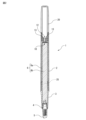
- FIG. 2 is a vertical cross-sectional view of the writing instrument of FIG.
- FIG. 3 is an exploded perspective view of the writing instrument of FIG.
- FIG. 4 is a vertical cross-sectional view of the ink storage member.
- FIG. 5 is another vertical cross-sectional view of the ink storage member.
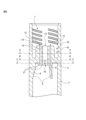
- FIG. 6 is an enlarged vertical cross-sectional view of the rear end portion of the barrel.
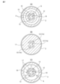
- FIG. 7 is a cross-sectional view of the ink refill section.
- FIG. 8 is a partial cross-sectional perspective view of the barrel showing the ink refill section.
- FIG. 9 is another partial perspective cross-sectional view of the barrel showing the ink refill section.
- FIG. 10 is a perspective view of the lead holding member.
- FIG. 11 is a vertical cross-sectional view of the lead holding member.
- FIG. 12 is a cross-sectional view taken along line DD of FIG.
- FIG. 1 is a perspective view of a writing instrument according to an embodiment of the present invention
- FIG. 2 is a vertical cross-sectional view of the writing instrument of FIG. 1
- FIG. 3 is an exploded perspective view of the writing instrument of FIG. 1.
- the writing instrument 1 comprises a cylindrical barrel 2, a cylindrically formed front barrel 3 that fits inside the front end of the barrel 2, a lead retaining member 4 that fits inside the front end of the front barrel 3, a writing lead 5 held by the lead retaining member 4, an ink occluder 6 that is disposed inside the barrel 2 and is impregnated with ink, and a cylindrically formed ink storage member 20 that screws into the rear end of the barrel 2.
- An ink refill section 10 is formed on the inner surface of the barrel 2 near the rear end.
- the barrel 2 may be referred to as including the lead barrel 3 and further including the ink storage member 20.
- the side of the writing lead 5 is defined as the "front” side, and the side opposite the writing lead 5 is defined as the "rear” side.
- the front and rear are defined based on the assembled state of the writing instrument 1.
- the central axis refers to the central axis of the writing instrument 1, i.e., the barrel 2.
- the writing instrument 1 is a writing instrument configured to eject ink induced from the ink occlusion body 6 from the writing core 5, and is specifically a marking pen.
- the writing core 5 is composed of a porous body such as a sintered body, a fiber bundle, a foam, a sponge body, a felt body, or a porous body.
- the writing core 5 is a roughly U-shaped member, and both ends of the U are inserted into the ink occlusion body 6.
- the ink in the ink occlusion body 6 is guided to the entire writing core 5 by capillary force, making it possible to eject the ink when writing.
- the writing instrument 1 may be a paint marker, an oil-based marker, a water-based marker, etc., as long as it is a writing instrument configured to eject ink induced from the ink occlusion body 6 from the writing core 5, and the shape of the writing core 5 may be formed as desired depending on the type of writing instrument.
- the ink occlusion body 6 When the ink guided from the ink occlusion body 6 runs out due to writing and writing with the writing instrument 1 becomes impossible, the ink occlusion body 6 can be replenished with ink. Specifically, the ink storage member 20 is removed from the rear end of the barrel 2, and a new ink storage member 20 filled with ink is fitted in its place. The ink storage member 20 will be described with reference to Figures 4 and 5.
- Figure 4 is a vertical cross-sectional view of the ink storage member 20, and Figure 5 is another vertical cross-sectional view of the ink storage member 20.
- the top is the front side.
- Figure 4 shows the ink storage member 20 in an unused state.
- One end, i.e., the rear end, of the ink storage member 20 is closed, allowing ink 25 to be stored inside.
- the other end, i.e., the front end, of the ink storage member 20 is open.
- a lid member 30 is fitted into the front end of the unused ink storage member 20 to prevent ink 25 from leaking out.
- FIG. 5 shows the ink storage member 20 with the cover member 30 removed.
- the front end of the ink storage member 20 is formed with a small diameter section 21 that is smaller in diameter than the rear part.
- the outer circumferential surface of the small diameter section 21 is formed with a male thread section 22.
- the threads of the male thread section 22 are not formed in a continuous spiral shape, but are formed as intermittent threads arranged on a continuous spiral trajectory. That is, the threads of the male thread section 22 are formed at equal intervals along the spiral direction for a length corresponding to a predetermined rotation angle around the central axis.
- By forming the threads regularly a plurality of sets of threads aligned in the axial direction are formed at equal intervals along the circumferential direction.
- the inner circumferential surface of the front end of the ink storage member 20 is formed with an annular protrusion 23.
- the inner circumferential surface of the rear end of the barrel 2 is formed with a female thread section 7 of the same shape that can be screwed with the male thread section 22 of the ink storage member 20.
- a closure member 31 that fits with the inner peripheral surface of the front end of the ink storage member 20 is formed on the inside of the front end surface of the lid member 30.
- the closure member 31 is a cylindrical protrusion extending rearward, and a mating protrusion 32 is formed in an annular shape on the outer peripheral surface of the closure member 31.
- a female thread portion (not shown) that can be screwed with the male thread portion 22 of the ink storage member 20 is formed on the inner peripheral surface of the lid member 30.
- the mating protrusion 32 of the closure member 31 inserted inside the ink storage member 20 and the annular protrusion 23 of the ink storage member 20 overcome each other while undergoing elastic deformation, thereby completing the screwing.
- the sealing performance between the ink storage member 20 and the closure member 31 is improved, and leakage of ink from the ink storage member 20 is prevented.
- the cover member 30 onto the ink storage member 20 filled with ink the ink storage member 20 can be stored and transported in an unused state.
- the outer peripheral surface of the ink storage member 20 is formed so as to be flush with, i.e., integral with, the outer peripheral surface of the barrel 2 when attached to the barrel 2.
- the outer peripheral surface of the cover member 30 is also formed so as to be flush with, i.e., integral with, the outer peripheral surface of the ink storage member 20.
- the cover member 30 is removed from the unused ink storage member 20 with the front end facing upward to prevent ink leakage.
- the ink storage member 20 that has already been attached is removed from the barrel 2, and instead, an unused ink storage member 20 is attached to the barrel 2 by screwing it in with the writing lead 5 of the writing instrument 1 facing upward.
- gravity moves the ink 25 inside the ink storage member 20 into the barrel 2 and further passes through the ink refill section 10.
- the ink 25 that has passed through the ink refill section 10 is supplied to the ink occluder 6, completing the ink refill.
- the ink refill section 10 will be described with reference to Figures 6 to 9.
- FIG. 6 is an enlarged vertical cross-sectional view of the rear end of the barrel 2.
- FIG. 7 is a horizontal cross-sectional view of the ink refill section 10. Specifically, FIG. 7(A) is a cross-sectional view taken along line A-A in FIG. 6, FIG. 7(B) is a cross-sectional view taken along line B-B in FIG. 6, and FIG. 7(C) is a cross-sectional view taken along line C-C in FIG. 6.
- FIG. 8 is a partial cross-sectional perspective view of the barrel showing the ink refill section 10, and FIG. 9 is another partial cross-sectional perspective view of the barrel showing the ink refill section 10. Specifically, FIGS.
- FIG. 8 and 9 are perspective views of the barrel 2 cut out in the vicinity of the ink refill section 10, with FIG. 8 being a perspective view of the ink refill section 10 as viewed from the rear side of the barrel 2, and FIG. 9 being a perspective view of the ink refill section 10 as viewed from the front side of the barrel 2.
- a female threaded portion 7 that can be screwed into the male threaded portion 22 of the ink storage member 20 is formed near the rear end of the barrel 2.
- the female threaded portion 7 has a plurality of threads that are arranged in the same spiral shape, aligned in the axial direction, and formed at equal intervals along the circumferential direction, just like the male threaded portion 22 of the ink storage member 20.
- an ink refill portion 10 is formed on the inner surface near the rear end of the barrel 2.
- the ink refill portion 10 has a partition wall 11 that crosses the inner surface of the barrel 2, and the partition wall 11 is provided with an air hole 12 and two ink discharge holes 13 that penetrate the partition wall 11 in the axial direction.
- Three ribs 8 are formed in front of the partition wall 11 and are arranged at equal intervals along the circumferential direction.
- the ribs 8 have a slope 9 facing forward.
- the ink occlusion body 6 inserted into the barrel 2 from the front is guided toward the center by the slope 9 of the rib 8 so that the central axes of the barrel 2 and the ink occlusion body 6 coincide.
- the ink occlusion body 6 is fixed to the barrel 2 so that it is sandwiched between the ribs 8.
- a first cylindrical wall 14 is formed in a cylindrical shape from the partition wall 11 toward the rear, and a second cylindrical wall 15 is formed in a cylindrical shape to surround the first cylindrical wall 14.
- the central axes of the first cylindrical wall 14 and the second cylindrical wall 15 coincide with the central axis of the barrel 2.
- a fitting space 16 is defined between the outer peripheral surface of the second cylindrical wall 15 and the inner peripheral surface of the barrel 2.
- the partition 11 has a circular through hole 11a that is equal to the inner diameter of the first cylindrical wall 14.
- a cylindrical air hole 12 is defined by the through hole 11a that penetrates the interior of the first cylindrical wall 14 and the partition 11. Therefore, the air hole 12 is provided on the central axis of the barrel 2, and communicates with the front and rear of the partition 11.
- two arc-shaped through holes 11b are formed around the through hole 11a of the partition 11, corresponding to a part of the cylindrical space defined between the first cylindrical wall 14 and the second cylindrical wall 15.
- the two through holes 11b are arranged symmetrically with respect to the central axis.
- two donut-shaped abutment protrusions 17 are formed from the partition toward the front.
- the two abutment protrusions 17 are equally divided by a slit 18 extending in the radial direction and arranged symmetrically.
- the diameter of the circumscribing circle of the two abutment protrusions 17 is formed to be smaller than the outer diameter of the ink occlusion body 6.
- the two through holes 11b penetrate the corresponding abutment protrusions 17 in the axial direction.
- Two ink ejection holes 13 are defined by the cylindrical space defined between the first cylindrical wall 14 and the second cylindrical wall 15, and the two through holes 11b penetrating the partition 11 and the abutment protrusions 17. Therefore, the two ink ejection holes 13 are arranged concentrically around the central axis of the barrel 2, and communicate with the front and rear of the partition wall 11.
- an unused ink storage member 20 is screwed onto the barrel 2 with the writing lead 5 of the writing instrument 1 facing upward, and then the writing instrument 1 is tilted so that the writing lead 5 faces downward.
- the ink inside the ink storage member 20 passes through the ink ejection hole 13 of the ink refill section 10 by gravity and is supplied to the inside of the ink absorbing body 6 from the rear end face of the ink absorbing body 6.
- the ink descends along the wall surface of the ink storage member 20.
- the ink ejection hole 13 is located farther away from the central axis of the barrel 2 or the ink storage member 20 than the air vent 12, i.e., radially outward from the air vent 12, so that the ink continues to descend through the ink ejection hole 13 before the air vent 12.
- the front end face of the contact protrusion 17, which is the outlet of the ink ejection hole 13 is in contact with the ink occlusion body 6, specifically the fibrous body 6b described below, so that the ink that passes through the ink ejection hole 13 can be directly supplied to the ink occlusion body 6.
- the through hole 11a in the partition 11, which is the entrance of the ventilation hole 12, is separated from the ink occlusion body 6 by the abutment protrusions 17, and therefore communicates with the slit 18 between the two abutment protrusions 17.
- the slit 18 communicates with the inside of the barrel 2, specifically the space between the inner circumferential surface of the barrel 2 and the outer circumferential surface of the ink occlusion body 6, and therefore the ventilation hole 12 communicates with the inside of the barrel 2.
- the ink when ink is supplied to the rear end surface of the ink occlusion body 6, the ink gradually permeates from the rear to the front. As the ink permeates, the air inside the ink occlusion body 6 also gradually moves from the rear to the front and is discharged from the front end surface of the ink occlusion body 6. The air pushed out from the front end surface of the ink occlusion body 6 passes through the space between the inner circumferential surface of the barrel 2 and the outer circumferential surface of the ink occlusion body 6, and flows into the ink storage member 20 through the ventilation hole 12.
- refilling the ink in the writing instrument 1 is accomplished by simply removing the ink storage member 20 that is attached to the rear end of the writing instrument 1 and that is already empty of ink, and then simply attaching an unused ink storage member 20. Therefore, unlike the writing instrument described in Patent Document 1, there is no need to remove the plug having the pen tip, so there is no risk of fingers or the like becoming soiled by the writing core 5, and there is no need to worry about ink spilling during the refilling process. Therefore, with the writing instrument 1, refilling the ink can be accomplished easily and quickly.
- the cross-sectional area of the ink ejection hole 13 is formed to be smaller than that of the ventilation hole 12. Therefore, assuming that the same ink passes through, the capillary force in the ink ejection hole 13, which has a smaller cross-sectional area and is a narrower flow path, is greater than the capillary force in the ventilation hole 12, which has a larger cross-sectional area and is a wider flow path. Therefore, when the ink passes through the ink ejection hole 13, the flow of the ink can be promoted by the action of the capillary force.
- the writing instrument 1 is configured such that when the ink storage member 20 is attached to the rear end of the barrel 2, refill ink in the ink storage member 20 can be supplied to the ink occlusion body 6 through the ink discharge hole 13 of the ink refill section 10.
- the ink refill section 10 only needs to be located behind the ink occlusion body 6, and therefore may be located inside the ink storage member 20 rather than inside the barrel 2.
- the ink refill section 10 may be configured as a separate body and may be inserted into the barrel 2 or the ink storage member 20.
- the shape, number and arrangement of the ventilation holes 12 and the ink discharge holes 13 can be selected arbitrarily, so long as the ventilation holes 12 are located closer to the central axis of the barrel 2 than the ink discharge holes 13 so that the ink passes through the ink discharge holes 13 first when the writing instrument 1 is tilted.
- the ventilation holes 12 are preferably located on the central axis, but may be off the central axis.
- the ink ejection holes 13 are preferably arranged concentrically around the central axis of the barrel 2, but do not have to be arranged concentrically.
- the ink supplied to the ink absorbing body 6 from the ink storage member 20 via the ink refill section 10 permeates the entire ink absorbing body 6 due to the action of capillary force within the ink absorbing body 6. This eliminates uneven ink ejection during writing and makes it possible to use the ink without waste. Taking into account the difference in fluidity between air and ink, it is preferable that the ink absorbing body 6 have at least two types of capillary force. The ink absorbing body 6 is described below.
- the ink absorbing body 6 is composed of an outer skin 6a and a fibrous body 6b, which is a bundle of multiple long fibers arranged in the longitudinal direction.
- fibers include fibers made of natural fibers, animal hair fibers, polyacetal resins, acrylic resins, and polyester resins.
- the ink absorbing body 6 is formed into a cylindrical shape as a whole by the outer skin 6a surrounding the fibrous body 6b. At both ends of the ink absorbing body 6, the fibrous body 6b is cut and aligned, and the exposed fibrous body 6b forms circular end faces.
- the outer skin 6a is a sheet-like member.
- the outer skin 6a may be made of a material that does not have capillary force, such as a synthetic resin film, or may be made of a material that has capillary force, such as a nonwoven fabric.
- a breathable material such as a nonwoven fabric
- the fibrous body 6b In the fibrous body 6b, countless flow paths for ink and air are formed by the tiny gaps between the fibers.
- the ink when ink is supplied from the ink absorbing body 6 to the ink absorbing body 6, i.e., the fibrous body 6b, the ink penetrates into the tiny gaps between the fibers. In the tiny gaps, the ink permeates throughout the entire fibrous body 6b due to capillary force.
- the density of the fibers that make up the fibrous body 6b i.e., the size of the gaps between the fibers
- the density of the fibers that make up the fibrous body 6b can be adjusted, for example, by the thickness of the fibers.
- the fibrous body 6b When the fibrous body 6b is made of thicker and thinner fibers, the fibrous body 6b has two types of capillary force. However, when the fibrous body 6b is made of fibers of different thicknesses, the fibers are not mixed, but are unevenly distributed with fibers of the same thickness. The portion made of thicker fibers has larger gaps than the portion made of thinner fibers, and therefore the capillary force is smaller. With an ink absorbing body 6 made of fibrous body 6b made of fibers of two types of thicknesses, the supplied ink is preferentially sucked into the gaps between the thinner fibers, which have a stronger capillary force, so the gaps between the thicker fibers become air flow paths, facilitating the discharge of air.
- the fibrous body 6b may be made of fibers of three or more types of thicknesses.
- the cylindrical ink occlusion body 6 has an outer diameter of 6.5 mm and a total length of 60 mm, and Examples 1 to 8 and Comparative Examples 1 and 2 were prepared as follows.
- the ink occlusion body is set on a writing instrument that has an ink refill section, i.e., a writing instrument that has two types of flow paths, an air hole and an ink ejection hole.
- the ink occlusion body is set on a writing instrument that does not have an ink refill section, i.e., a writing instrument with no barrier between the ink storage member and the ink occlusion body.
- Example 1 An ink occlusion body obtained by enclosing a fibrous body consisting of 11,000 fibers of 3 dtex and 460 fibers of 2 dtex in an outer skin of a PET film was set in a writing implement having an ink refill section.
- Example 2 An ink occlusion body obtained by enclosing a fibrous body consisting of 12,000 fibers of 3 dtex and 500 fibers of 2 dtex in an outer skin of a PET film was set in a writing implement having an ink refill section.
- Example 3 An ink occlusion body obtained by enclosing a fibrous body consisting of 10,000 fibers of 3 dtex and 400 fibers of 2 dtex in an outer skin of a PET film was set in a writing implement having an ink refill section.
- Example 4 An ink occlusion body obtained by enclosing a fibrous body consisting of 10,000 fibers of 3 dtex and 50 fibers of 15 dtex in an outer skin of a PET film was set in a writing implement having an ink refill section.
- Example 5 An ink occlusion body obtained by enclosing a fibrous body consisting of 9,000 fibers of 3 dtex, 460 fibers of 2 dtex, and 50 fibers of 15 dtex in an outer skin of a PET film was set in a writing implement having an ink refill section.
- Example 6 An ink occlusion body obtained by surrounding a fibrous body consisting of 12,000 fibers of 3 dtex with an outer skin consisting of a nonwoven fabric was set in a writing implement having an ink refill section.
- Example 7 An ink occlusion body obtained by enclosing a fibrous body consisting of 12,000 fibers of 3 dtex in an outer skin consisting of a PET film was set in a writing implement having an ink refill section.
- Example 8 An ink occlusion body obtained by enclosing a fibrous body consisting of 14,000 fibers of 3 dtex in an outer skin consisting of a PET film was set in a writing implement having an ink refill section.
- Comparative Example Comparative Example 1 An ink occlusion body obtained by surrounding a fibrous body consisting of 12,000 fibers of 3 dtex with an outer skin consisting of a PET film was set in a writing implement having no ink refill section.
- Comparative Example 2 An ink occlusion body obtained by enclosing a fibrous body consisting of 14,000 fibers of 3 dtex in an outer skin consisting of a PET film was set in a writing implement having no ink refill section.
- Example 1 to 8 were 25 seconds in Example 1, 20 seconds in Example 2, 30 seconds in Example 3, 15 seconds in Examples 4 to 6, 45 seconds in Example 7, and 40 seconds in Example 8.
- the ink impregnation times in Examples 1 to 8 were all within 1 minute, and in particular, the ink impregnation times in Examples 1 to 6 were all good, being within 30 seconds.
- Comparative Examples 1 and 2 a portion of the ink remained unimpregnated even after 600 seconds had elapsed in both Comparative Examples 1 and 2.
- Examples 7 and 8 and the corresponding Comparative Examples 1 and 2 The only difference between Examples 7 and 8 and the corresponding Comparative Examples 1 and 2 is the presence or absence of an ink refill section.
- the ink forms a concave film due to surface tension inside the barrel behind the ink occluder or on the inner surface of the ink storage member. In this state, if the writing instrument is tilted to move the ink forward, in Comparative Examples 1 and 2 that do not have an ink refill section, the ink does not come into contact with the ink occluder properly, and therefore the ink does not penetrate the ink occluder properly.
- Examples 1 to 8 that have the ink refill section 10 when the entrance of the ink discharge hole 13 comes into contact with the ink liquid surface, the ink is sucked into the ink discharge hole 13 by the action of capillary force. As a result, the ink is discharged from the exit of the ink discharge hole 13 and is efficiently supplied to the ink occluder 6 in sequence.
- the ink soaking time was the shortest at 15 seconds, and the reason for this is as follows. That is, the ink occlusion bodies of Examples 4 and 5 contain thicker 15 dtex fibers compared to the other Examples, and the gaps between the fibers are larger compared to the other fibers. Therefore, inside one ink occlusion body, there are two types of capillary force: a stronger capillary force due to the narrower gaps between fibers such as 3 dtex, and a weaker capillary force due to the wider gaps between fibers of 15 dtex. This allows the flow of ink to be supplied and the flow of air to be discharged to be efficient.
- Example 6 the outer skin is made of nonwoven fabric, so air can be effectively discharged from the inside of the ink occlusion body 6 to the outside when ink is refilled, and the flow of ink to be supplied and the flow of air to be discharged to be efficient.
- the ink occlusion bodies of Examples 1 to 3 contain 2 dtex fibers and 3 dtex fibers, but do not contain 15 dtex fibers. Therefore, the ink soaking time is longer than that of the ink occlusion bodies of Examples 4 and 5, which contain 15 dtex fibers, but the flow of the ink supplied and the flow of the air discharged are efficient.
- the ink absorbing body is configured to have at least two types of capillary force.
- the two types of capillary force may be capillary force obtained due to differences in the fibers that make up the fibrous body, and the effect obtained from the material of the outer skin, such as nonwoven fabric, may also be referred to as capillary force.
- the fibrous body may contain one type of fiber and be formed with a material such as nonwoven fabric as the outer skin, thereby having two or more types of capillary force.
- the ink occlusion body may be configured not only from a fibrous body made of fibers, but also from a porous body such as a sponge, resin particles, or a sintered body.
- Fig. 10 is a perspective view of the lead holding member 4
- Fig. 11 is a longitudinal cross-sectional view of the lead holding member 4
- Fig. 12 is a cross-sectional view taken along line D-D in Fig. 11.
- the lead holding member 4 has a main body 40 formed in a trapezoidal flat plate shape, a fitting portion 41 provided at the rear of the main body 40 and configured to fit inside the front end of the tip barrel 3, a retaining groove 42 provided on the outer periphery of the main body 40 and the fitting portion 41 and configured to fit the approximately U-shaped writing lead 5, and a visible portion 43 provided on the side of the main body 40.
- the visible portion 43 consists of a through hole 44 provided in the main body portion 40 and three beam members 45 extending in the longitudinal direction of the core holding member 4 inside the through hole 44.
- Each of the beam members 45 has a rectangular cross section with approximately the same width and height, as shown in FIG. 12.
- the lead holding member 4 is prevented from bending excessively due to the writing pressure applied when writing.
- the number, shape, width dimension, etc. of the beam members 45 it is possible to adjust the flexibility of the lead holding member 4.
- the user can visually recognize the characters written in the writing direction through the visible portion 43, particularly the through hole 44.
- the beam member 45 is provided to extend in the longitudinal direction of the through hole 44, but may also be provided to extend in an oblique direction or in the lateral direction rotated by 90 degrees.
- the lead holding member 4 is preferably made of a synthetic resin material with a compression set of less than 80% at 120°C and a Shore A hardness of 60 to 95. Specifically, it is a styrene-based elastomer selected from the group consisting of styrene-ethylene-propylene-styrene (SEPS) in which styrene is replaced with p-methylstyrene, styrene-ethylene-ethylene-propylene-styrene (SEEPS) in which styrene is replaced with p-methylstyrene, and styrene-ethylene-butadiene-styrene (SEBS) in which styrene is replaced with p-methylstyrene.
- SEPS styrene-ethylene-propylene-styrene
- SEEPS styrene-ethylene-ethylene-propylene-styrene
- SEBS st
Landscapes
- Pens And Brushes (AREA)
Abstract
筆記具1が、軸筒2と、軸筒2内に配置され且つインクを含浸するインク吸蔵体6と、インク吸蔵体6よりも後方に配置され且つ通気孔12及びインク吐出孔13を有するインク補充部10と、軸筒2の後端部に取り付け可能で且つインクを収容可能なインク貯蔵部材20と、を具備し、インク貯蔵部材20を軸筒2の後端部に対して取り付けると、インク貯蔵部材20内のインクがインク補充部10のインク吐出孔13を介してインク吸蔵体6に対して供給可能となるように構成されている。
Description
本発明は、筆記具及びインク貯蔵部材に関する。
軸筒内に配置され且つインクを含浸するインク吸蔵体と、インク吸蔵体から誘導されたインクを吐出するペン先である筆記芯とを有する筆記具が公知である(例えば特許文献1)。こうした筆記具として、ペイントマーカー、油性マーカー、水性マーカー及びアンダーラインマーカー等が挙げられる。使用によってインク吸蔵体から誘導されるインクがなくなり、筆記具によって筆記ができなくなった場合には、環境保護の観点から、インク吸蔵体に対してインクが補充可能であることが好ましい。
特許文献1に記載の筆記具は、軸筒と、軸筒の内部に配置されたインク吸蔵体と、ペン先を保持した栓体とを有している。インクを補充するためには、軸筒から栓体を取り外し、インクが収容された補充具を軸筒の前端部から挿入し、インク吸蔵体に対してインクを供給することができる。
特許文献1に記載の筆記具では、栓体を取り外すときにペン先に触れることで手指等が汚れる可能性がある。また、軸筒の後端部が閉鎖されていることから、インクの供給時にインク吸蔵体内の空気と供給されたインクとの置換が適切に行われず、供給したインクが、インク吸蔵体、ひいては軸筒から溢れる可能性がある。補充具からゆっくりとインクを供給すれば、インクが溢れることが防止されるが、補充に時間がかかり過ぎる場合がある。
本発明は、インク吸蔵体に対するインクの補充を簡易且つ迅速に行うことができる筆記具を提供することを目的とする。
本発明の一態様によれば、軸筒と、前記軸筒内に配置され且つインクを含浸するインク吸蔵体と、前記インク吸蔵体よりも後方に配置され且つ通気孔及びインク吐出孔を有するインク補充部と、前記軸筒の後端部に取り付け可能で且つインクを収容可能なインク貯留部材と、を具備し、前記インク貯留部材を前記軸筒の後端部に対して取り付けると、前記インク貯留部材内の前記インクが前記インク補充部の前記インク吐出孔を介して前記インク吸蔵体に対して供給可能となるように構成されていることを特徴とする筆記具が提供される。
本発明の別態様によれば、通気孔及びインク吐出孔を有するインク補充部と、インクを含浸するインク吸蔵体が内部に配置された軸筒の後端部に装着可能で且つインクが収容された、筆記具用のインク貯蔵部材であって、前記軸筒の後端部に対して装着すると、前記インクが前記インク補充部の前記インク吐出孔を介して前記インク吸蔵体に対して供給されるように構成されていることを特徴とするインク貯蔵部材が提供される。
前記通気孔が前記インク吐出孔よりも前記軸筒の中心軸線寄りに設けられていてもよい。前記通気孔が前記中心軸線上に設けられていてもよい。前記インク吐出孔が、前記中心軸線回りに同心円状に設けられていてもよい。前記インク吸蔵体が、少なくとも2種類の毛細管力を有するように構成されていてもよい。
本発明の態様によれば、インク吸蔵体に対するインクの補充を簡易且つ迅速に行うことができる筆記具を提供するという共通の効果を奏する。
以下、図面を参照しながら本発明の実施の形態を詳細に説明する。全図面に亘り、対応する構成要素には共通の参照符号を付す。
図1は、本発明の実施形態による筆記具の斜視図であり、図2は、図1の筆記具の縦断面図であり、図3は、図1の筆記具の分解斜視図である。
筆記具1は、筒状に形成された軸筒2と、軸筒2の前端部の内部に嵌合し且つ筒状に形成された先軸3と、先軸3の前端部の内部に嵌合する芯保持部材4と、芯保持部材4によって保持された筆記芯5と、軸筒2の内部に配置され且つインクを含浸するインク吸蔵体6と、軸筒2の後端部の内部に螺合し筒状に形成されたインク貯蔵部材20とを有している。軸筒2の後端部近傍の内面には、インク補充部10が形成されている。なお、先軸3も含めて、さらにはインク貯蔵部材20も含めて軸筒2と称してもよい。
本明細書中では、筆記具1の軸線方向において、筆記芯5側を「前」側と規定し、筆記芯5とは反対側を「後」側と規定する。各部材の説明では、筆記具1として組み立てられた状態を基準に前側及び後側を規定する。また、特に断りのない限り、中心軸線とは、筆記具1、すなわち軸筒2の中心軸線を意味する。
筆記具1は、インク吸蔵体6から誘導されたインクを筆記芯5から吐出するよう構成された筆記具であり、具体的には、マーキングペンである。筆記芯5は、例えば、焼結体、繊維束体、発泡体、海綿体、フェルト体及びポーラス体等の多孔体から構成される。筆記芯5は、略U字状の部材であり、U字の両端部分は、インク吸蔵体6内に挿入されている。インク吸蔵体6内のインクは毛細管力によって筆記芯5全体に誘導され、筆記時のインクの吐出が可能となる。なお、筆記具1は、インク吸蔵体6から誘導されたインクを筆記芯5から吐出するよう構成された筆記具である限り、ペイントマーカー、油性マーカー及び水性マーカー等であってもよく、筆記芯5の形状は、筆記具の種類に応じて任意に形成してもよい。
筆記によってインク吸蔵体6から誘導されるインクがなくなり、筆記具1によって筆記ができなくなった場合には、インク吸蔵体6に対してインクを補充することができる。具体的には、軸筒2の後端部からインク貯蔵部材20を取り外し、その代わりに、インクが充填された新しいインク貯蔵部材20を嵌合する。インク貯蔵部材20について、図4及び図5を参照しながら説明する。
図4は、インク貯蔵部材20の縦断面図であり、図5は、インク貯蔵部材20の別の縦断面図である。図4及び図5において、上方が前側である。図4は、未使用状態のインク貯蔵部材20を示している。インク貯蔵部材20は、一方の端部、すなわち後端が閉鎖しており、インク25を内部に貯留可能となっている。インク貯蔵部材20の他方の端部、すなわち前端は開口している。未使用状態のインク貯蔵部材20の前端部には、インク25が漏出しないように蓋部材30が嵌合している。
図5は、蓋部材30を取り外したインク貯蔵部材20を示している。インク貯蔵部材20の前端部には、後方の部分よりも小径の小径部21が形成されている。小径部21の外周面には、雄ねじ部22が形成されている。図3に示されているように、雄ねじ部22のねじ山は、一連の螺旋状には形成されておらず、一連の螺旋の軌跡上に配置された断続的なねじ山として形成されている。すなわち、雄ねじ部22のねじ山は、中心軸線回りに所定回転角に対応する長さだけ、且つ、螺旋方向に沿って等間隔に形成されている。ねじ山が規則正しく形成されていることによって、軸線方向に整列した複数のねじ山の組が、周方向に沿って等間隔に形成されている。図5に示されているようにインク貯蔵部材20の前端部の内周面には、環状に形成された環状突起23が形成されている。なお、後述する図6に示されるように、軸筒2の後端部の内周面には、インク貯蔵部材20の雄ねじ部22と螺合可能で、同様の形状である雌ねじ部7が形成されている。
図4を参照すると、蓋部材30の前端面の内側には、インク貯蔵部材20の前端部の内周面と嵌合する閉鎖部材31が形成されている。閉鎖部材31は、後方に延びる筒状の突起であり、閉鎖部材31の外周面には嵌合突起32が環状に形成されている。蓋部材30の内周面には、インク貯蔵部材20の雄ねじ部22と螺合可能な雌ねじ部(図示せず。)が形成されている。インク貯蔵部材20と蓋部材30との螺合時には、インク貯蔵部材20の内部に挿入された閉鎖部材31の嵌合突起32及びインク貯蔵部材20の環状突起23が弾性変形を伴いながら互いに乗り越えることによって、螺合が完了する。その結果、インク貯蔵部材20及び閉鎖部材31間のシール性が向上し、インク貯蔵部材20からインクの漏出が防止される。また、内部にインクが充填されたインク貯蔵部材20に対して、蓋部材30を螺合させることによって、インク貯蔵部材20を未使用状態のまま保管及び運搬等を行うことができる。
インク貯蔵部材20の外周面は、図1及び図2に示されるように、軸筒2に取り付けられた状態で、軸筒2の外周面と面一になるように、すなわち一体的となるように形成されている。なお、蓋部材30の外周面も、インク貯蔵部材20の外周面と面一となるように、すなわち一体的となるように形成されている。
インクを補充するために、インクが漏れないように前端を上方に向けた状態で、未使用のインク貯蔵部材20から蓋部材30を取り外す。次いで、既に取り付けられているインク貯蔵部材20を軸筒2から取り外し、その代わりに、筆記具1の筆記芯5を上方に向けた状態で、軸筒2に対して未使用のインク貯蔵部材20を螺合によって取り付ける。次いで、筆記芯5が下方を向くよう筆記具1を傾けると、重力によって、インク貯蔵部材20の内部のインク25が、軸筒2内に移動し、さらにインク補充部10を通過する。インク補充部10を通過したインク25は、インク吸蔵体6に供給され、インクの補充が完了する。インク補充部10について、図6乃至図9を参照しながら説明する。
図6は、軸筒2の後端部の拡大縦断面図である。図7は、インク補充部10の横断面図である。具体的には、図7(A)は、図6の線A-Aによる断面図であり、図7(B)は、図6の線B-Bによる断面図であり、図7(C)は、図6の線C-Cによる断面図である。また、図8は、インク補充部10を示す軸筒の部分的な断面斜視図であり、図9は、インク補充部10を示す軸筒の部分的な別の断面斜視図である。具体的には、図8及び図9は、インク補充部10近傍の軸筒2を切り出した斜視図であって、図8は、インク補充部10を軸筒2の後方側から見た斜視図であり、図9は、インク補充部10を軸筒2の前方側から見た斜視図である。
軸筒2の後端部近傍には、インク貯蔵部材20の雄ねじ部22と螺合可能な雌ねじ部7が形成されている。雌ねじ部7は、インク貯蔵部材20の雄ねじ部22と同様に、同一螺旋状に配置され、軸線方向に整列し且つ周方向に沿って等間隔に形成された複数のねじ山を有している。上述したように、軸筒2の後端部近傍の内面には、インク補充部10が形成されている。インク補充部10は、軸筒2の内面を横断する隔壁11を有し、隔壁11には、隔壁11を軸線方向に貫通する、通気孔12及び2つのインク吐出孔13が設けられている。隔壁11の前方には、周方向に沿って等間隔に配置された3つのリブ8が形成されている。リブ8には、前方に面した斜面9が形成されている。軸筒2の前方から内部に挿入されたインク吸蔵体6は、軸筒2及びインク吸蔵体6の中心軸線が一致するよう、リブ8の斜面9によって中心に向かって案内される。それによって、インク吸蔵体6は、リブ8間に挟持されるように軸筒2に対して固定される。
特に図8に示されるように、隔壁11から後方に向かって、円筒状に第1円筒壁14が形成され、第1円筒壁14を包囲するよう円筒状に第2円筒壁15が形成されている。第1円筒壁14及び第2円筒壁15の各々の中心軸線は、軸筒2の中心軸線と一致している。第2円筒壁15の外周面及び軸筒2の内周面間には、嵌合空間16が画成される。なお、インク貯蔵部材20を軸筒2に対して取り付けたとき、嵌合空間16にはインク貯蔵部材20の小径部21が嵌合し、嵌合空間16が埋められる。それによって、インクを補充するときにインク貯蔵部材20から軸筒2内に流入したインクが、第2円筒壁15の周囲に溜まることが防止され、すべてのインクをインク吸蔵体6に含浸させることができる。
図7(B)に示されるように、隔壁11には、第1円筒壁14の内径と等しい円形の貫通孔11aが形成されている。第1円筒壁14の内部及び隔壁11を貫通する貫通孔11aによって、円柱状の通気孔12が画成される。したがって、通気孔12は、軸筒2の中心軸線上に設けられ、隔壁11の前方及び後方を連通している。
また、図7(B)に示されるように、隔壁11の貫通孔11aの周囲には、第1円筒壁14及び第2円筒壁15間に画成された円筒状の空間の一部に対応する円弧状の2つの貫通孔11bが形成されている。2つの貫通孔11bは、中心軸線に対して対称的に配置されている。図7(C)に示されるように、隔壁から前方に向かってドーナツ状の2つの当接突起17が形成されている。2つの当接突起17は、径方向に延びるスリット18によって等分され、対称的に配置されている。2つの当接突起17の外接円の径は、インク吸蔵体6の外径よりも小さく形成されている。2つの貫通孔11bは、対応する当接突起17を軸線方向に貫通している。第1円筒壁14及び第2円筒壁15間に画成された円筒状の空間、並びに、隔壁11及び当接突起17を貫通する2つの貫通孔11bによって、2つのインク吐出孔13が画成される。したがって、2つのインク吐出孔13は、軸筒2の中心軸線回りに同心円状に設けられ、隔壁11の前方及び後方を連通している。筆記具1の組立状態では、当接突起17の前端面はインク吸蔵体6の後端面によってすべて覆われることから、インク吐出孔13の出口は、インク吸蔵体6と当接している。
上述したように、インクを補充するため、筆記具1の筆記芯5を上方に向けた状態で、軸筒2に対して未使用のインク貯蔵部材20を螺合によって取り付け、次いで、筆記芯5が下方を向くよう筆記具1を傾ける。その結果、インク貯蔵部材20の内部のインクは、重力によってインク補充部10のインク吐出孔13を通り、インク吸蔵体6の後端面からインク吸蔵体6の内部に供給される。詳細には、筆記具1を傾けるに従って、インクはインク貯蔵部材20の壁面に沿って下降する。インク吐出孔13は、通気孔12よりも軸筒2又はインク貯蔵部材20の中心軸線から離間して、すなわち、通気孔12よりも径方向外方側に設けられているため、インクは、通気孔12よりも先にインク吐出孔13を通って下降を続ける。特に、インク吐出孔13の出口である当接突起17の前端面は、インク吸蔵体6、具体的には後述する線維体6bに対して当接しているため、インク吐出孔13を通ったインクを直接的にインク吸蔵体6に供給することができる。
通気孔12の入口である、隔壁11に設けられた貫通孔11aは、当接突起17によってインク吸蔵体6から離間していることから、2つの当接突起17間のスリット18と連通している。スリット18は、軸筒2内、具体的には軸筒2の内周面及びインク吸蔵体6の外周面間の空間と連通していることから、通気孔12は、軸筒2内と連通している。
上述したように、インク吸蔵体6の後端面にインクが供給されると、インクは後方から前方に向かって徐々に浸透する。インクの浸透に伴い、インク吸蔵体6内の空気も後方から前方に向かって徐々に移動し、インク吸蔵体6の前端面から排出される。インク吸蔵体6の前端面から押し出された空気は、軸筒2の内周面及びインク吸蔵体6の外周面間の空間を通って、通気孔12からインク貯蔵部材20側に流入する。要するに、インク吐出孔13を介してインクがインク吸蔵体6内に供給されると、その体積分のインク吸蔵体6内の空気が通気孔12を通ってインク貯蔵部材20側に流入する。インク吸蔵体6内において、インクの流動方向及び空気の流動方向が一致しているため、インクを素早く補充することができる。
さらに、筆記具1のインクの補充は、筆記具1の後端部に取り付けられ且つインクが既に空になっているインク貯蔵部材20を取り外し、単に未使用のインク貯蔵部材20を取り付けるだけで行われる。そのため、特許文献1に記載の筆記具のように、ペン先を有する栓体を取り外す必要がないことから、筆記芯5によって手指等が汚れる虞もなく、補充作業中のインクの溢れを気にする必要もない。したがって、筆記具1によれば、インクの補充を簡易且つ迅速に行うことができる。
インク吐出孔13の横断面積は、通気孔12の横断面積よりも小さくなるように形成されている。そのため、仮に同じインクが通過することを考慮した場合、より横断面積が小さく、細い流路であるインク吐出孔13における毛細管力が、より横断面積が大きく、太い流路である通気孔12における毛細管力よりも大きい。したがって、インクがインク吐出孔13を通過することによって、毛細管力の作用によりインクの流動を促進することができる。
以上より、筆記具1は、インク貯蔵部材20を軸筒2の後端部に対して取り付けると、インク貯蔵部材20内の補充用のインクがインク補充部10のインク吐出孔13を介してインク吸蔵体6に対して供給可能となるように構成されている。インク補充部10は、インク吸蔵体6よりも後方に配置されていればよく、したがって、軸筒2の内部ではなく、インク貯蔵部材20の内部に配置されていてもよい。インク補充部10を別体で構成し、軸筒2又はインク貯蔵部材20内に挿入可能にしてもよい。筆記具1を傾けたときにインクがインク吐出孔13を先に通過するように、通気孔12がインク吐出孔13よりも軸筒2の中心軸線寄りに設けられている限りにおいて、通気孔12及びインク吐出孔13の形状、個数及び配置は任意に選択可能である。通気孔12は、中心軸線上に設けられていることが好ましいが、中心軸線から外れていてもよい。インク吐出孔13は、軸筒2の中心軸線回りに同心円状に設けられていることが好ましいが、同心円状に設けられていなくてもよい。
インク貯蔵部材20からインク補充部10を介してインク吸蔵体6に供給されたインクは、インク吸蔵体6内における毛細管力の作用によって、インク吸蔵体6全体に亘り含浸する。それによって筆記時におけるインクの吐出の不均一を解消し、インクを無駄なく使用することが可能となる。インク吸蔵体6は、空気及びインクの流動性の違いを考慮し、少なくとも2種類の毛細管力を有することが好ましい。インク吸蔵体6について、以下説明する。
図2に示されるように、インク吸蔵体6は、外皮6aと長手方向に配置された複数の長線維の束である線維体6bとからなる。線維として、例えば、天然繊維、獣毛繊維、ポリアセタール系樹脂、アクリル系樹脂及びポリエステル系樹脂等からなる線維が挙げられる。インク吸蔵体6は、線維体6bを外皮6aが包囲することによって、全体として円柱状に形成されている。インク吸蔵体6の両端部では、線維体6bが切り揃えられ、露出した線維体6bによって円形の端面を形成する。
外皮6aは、シート状の部材である。外皮6aは、合成樹脂フィルム等の毛細管力を有しない材料で形成してもよく、不織布等の毛細管力を有する材料で形成してもよい。外皮6aを不織布等の通気性材料で形成することによって、インクの補充時にインク吸蔵体6の内部から外部へ空気を排出させることができる。
線維体6bには、繊維同士の微小な間隙によって、インク及び空気のための無数の流路が形成されている。上述したように、インク吸蔵体6からインク吸蔵体6、すなわち線維体6bにインクが供給されると、繊維同士の微小な間隙にインクが浸入する。インクは微小な間隙内において、毛細管力によって線維体6b全体に亘り浸透する。このとき、線維体6bを構成する繊維の粗密、すなわち線維同士の間隙の大小を調整することによって、毛細管力の大小を調整し、インクの浸透を促進することができる。線維体6bを構成する繊維の粗密は、例えば、線維の太さによって調整可能である。
線維体6bが、より太い線維とより細い線維とからなる場合、線維体6bは、2種類の毛細管力を有する。ただし、線維体6bを太さの異なる線維から構成する場合、異なる線維同士を混在させずに、同一太さの線維で偏在するよう構成する。より太い線維から構成される部分は、より細い線維からなる部分よりも間隙が大きいことから、毛細管力は小さくなる。2種類の太さの線維からなる線維体6bからなるインク吸蔵体6によれば、供給されたインクは、より毛細管力の大きいより細い線維同士の間隙に優先して吸引されるので、より太い線維同士の間隙は、空気の流路となり、空気の排出が促進される。線維体6bを、3種類以上の太さからなる線維で構成してもよい。
筆記具1のインク補充部10の有無、及び、インク吸蔵体6の線維体6bを構成する繊維の違いについて、具体的な実施例を用いて行った実験について以下説明する。
円柱状のインク吸蔵体6について、外径を6.5mmとし、全長を60mmとし、以下のとおり実施例1~8及び比較例1及び2を用意した。実施例1~8では、インク補充部を有する筆記具、すなわち通気孔及びインク吐出孔の2種類の流路を有する筆記具に対してインク吸蔵体をセットする。比較例1及び2では、インク補充部を有さない筆記具、すなわち、インク貯蔵部材とインク吸蔵体との間に遮蔽物のない筆記具に対してインク吸蔵体をセットする。
<実施例>
実施例1:3dtexの繊維11,000本及び2dtexの繊維460本からなる線維体をPETフィルムからなる外皮で包囲して得たインク吸蔵体をインク補充部を有する筆記具にセットした。
実施例2:3dtexの繊維12,000本及び2dtexの繊維500本からなる線維体をPETフィルムからなる外皮で包囲して得たインク吸蔵体をインク補充部を有する筆記具にセットした。
実施例3:3dtexの繊維10,000本及び2dtexの繊維400本からなる線維体をPETフィルムからなる外皮で包囲して得たインク吸蔵体をインク補充部を有する筆記具にセットした。
実施例4:3dtexの繊維10,000本及び15dtexの繊維50本からなる線維体をPETフィルムからなる外皮で包囲して得たインク吸蔵体をインク補充部を有する筆記具にセットした。
実施例5:3dtexの繊維9,000本及び2dtexの繊維460本及び15dtexの繊維50本からなる線維体をPETフィルムからなる外皮で包囲して得たインク吸蔵体をインク補充部を有する筆記具にセットした。
実施例6:3dtexの繊維12,000本からなる線維体を不織布からなる外皮で包囲して得たインク吸蔵体をインク補充部を有する筆記具にセットした。
実施例7:3dtexの繊維12,000本からなる線維体をPETフィルムからなる外皮で包囲して得たインク吸蔵体をインク補充部を有する筆記具にセットした。
実施例8:3dtexの繊維14,000本からなる線維体をPETフィルムからなる外皮で包囲して得たインク吸蔵体をインク補充部を有する筆記具にセットした。
<比較例>
比較例1:3dtexの繊維12,000本からなる線維体をPETフィルムからなる外皮で包囲して得たインク吸蔵体をインク補充部を有さない筆記具にセットした。
比較例2:3dtexの繊維14,000本からなる線維体をPETフィルムからなる外皮で包囲して得たインク吸蔵体をインク補充部を有さない筆記具にセットした。
実施例1:3dtexの繊維11,000本及び2dtexの繊維460本からなる線維体をPETフィルムからなる外皮で包囲して得たインク吸蔵体をインク補充部を有する筆記具にセットした。
実施例2:3dtexの繊維12,000本及び2dtexの繊維500本からなる線維体をPETフィルムからなる外皮で包囲して得たインク吸蔵体をインク補充部を有する筆記具にセットした。
実施例3:3dtexの繊維10,000本及び2dtexの繊維400本からなる線維体をPETフィルムからなる外皮で包囲して得たインク吸蔵体をインク補充部を有する筆記具にセットした。
実施例4:3dtexの繊維10,000本及び15dtexの繊維50本からなる線維体をPETフィルムからなる外皮で包囲して得たインク吸蔵体をインク補充部を有する筆記具にセットした。
実施例5:3dtexの繊維9,000本及び2dtexの繊維460本及び15dtexの繊維50本からなる線維体をPETフィルムからなる外皮で包囲して得たインク吸蔵体をインク補充部を有する筆記具にセットした。
実施例6:3dtexの繊維12,000本からなる線維体を不織布からなる外皮で包囲して得たインク吸蔵体をインク補充部を有する筆記具にセットした。
実施例7:3dtexの繊維12,000本からなる線維体をPETフィルムからなる外皮で包囲して得たインク吸蔵体をインク補充部を有する筆記具にセットした。
実施例8:3dtexの繊維14,000本からなる線維体をPETフィルムからなる外皮で包囲して得たインク吸蔵体をインク補充部を有する筆記具にセットした。
<比較例>
比較例1:3dtexの繊維12,000本からなる線維体をPETフィルムからなる外皮で包囲して得たインク吸蔵体をインク補充部を有さない筆記具にセットした。
比較例2:3dtexの繊維14,000本からなる線維体をPETフィルムからなる外皮で包囲して得たインク吸蔵体をインク補充部を有さない筆記具にセットした。
<実験方法>
あらかじめインク吸蔵体にインクを1.7gだけ含浸し、筆記によってインクを1.3g分吐出させる。次いで、未使用のインク貯蔵部材を軸筒に対して取り付け、インク吸蔵体に対してインクを1.2gだけ供給する。供給されたインクが、インク吸蔵体内にすべて含浸するまでの含浸時間を測定した。
あらかじめインク吸蔵体にインクを1.7gだけ含浸し、筆記によってインクを1.3g分吐出させる。次いで、未使用のインク貯蔵部材を軸筒に対して取り付け、インク吸蔵体に対してインクを1.2gだけ供給する。供給されたインクが、インク吸蔵体内にすべて含浸するまでの含浸時間を測定した。
<実験結果>
実施例1~8におけるインクの含浸時間について、実施例1は25秒、実施例2は20秒、実施例3は30秒、実施例4~6は15秒、実施例7は45秒、実施例8は40秒であった。実施例1~8におけるインクの含浸時間はいずれも1分以内であり、特に実施例1~6におけるインクの含浸時間はいずれも30秒以内と良好であった。他方、比較例1及び2におけるインクの含浸時間について、比較例1及び2のいずれも600秒経過後も一部のインクが含浸されずに残っていた。
実施例1~8におけるインクの含浸時間について、実施例1は25秒、実施例2は20秒、実施例3は30秒、実施例4~6は15秒、実施例7は45秒、実施例8は40秒であった。実施例1~8におけるインクの含浸時間はいずれも1分以内であり、特に実施例1~6におけるインクの含浸時間はいずれも30秒以内と良好であった。他方、比較例1及び2におけるインクの含浸時間について、比較例1及び2のいずれも600秒経過後も一部のインクが含浸されずに残っていた。
実施例7及び8と対応する比較例1及び2とは、インク補充部の有無においてのみ相違するが、上述したとおり、インクの含浸時間について大きな差があり、インク補充部の有効性が明らかとなった。詳細には、インク吸蔵体の後方の軸筒内又はインク貯蔵部材の内面で、インクは表面張力による凹面状の膜を形成する。この状態で、筆記具を傾けてインクを前方へ移動させた場合、インク補充部を有さない比較例1及び2では、インクとインク吸蔵体との接触が適切に行われず、したがって、インクがインク吸蔵体に適切に浸透しにくい。他方、インク補充部10を有する実施例1~8では、インクの液面にインク吐出孔13の入口が接すると、毛細管力の作用によって、インクがインク吐出孔13の内部に吸引される。その結果、インクは、インク吐出孔13の出口から吐出されてインク吸蔵体6に対して順次効率良く供給される。
実施例4~6は、いずれもインクの含浸時間が15秒と最短であったが、その理由は次の通りである。すなわち、実施例4及び5のインク吸蔵体は、他の実施例と比較して、より太い15dtexの繊維を含んでおり、線維同士の間隙が他の線維と比較してより大きくなる。そのため、1つのインク吸蔵体の内部に、3dtex等の繊維同士のより狭い間隙によるより強い毛細管力と、15dtexの繊維の線維同士のより広い間隙によるより弱い毛細管力との、2種類の毛細管力を有する。それによって、供給されるインクの流動と排出される空気の流動とが効率良く行われる。実施例6は、外皮が不織布からなることから、インクの補充時にインク吸蔵体6の内部から外部へ空気を良好に排出させることができ、供給されるインクの流動と排出される空気の流動とが効率良く行われる。実施例1~3のインク吸蔵体は、2dtexの繊維及び3dtexの繊維を含んでおり、15dtexの繊維を含んでいない。そのため、15dtexの繊維を含む実施例4及び5のインク吸蔵体よりは、インクの含浸時間が長いが、供給されるインクの流動と排出される空気の流動とが効率良く行われる。
以上より、インク吸蔵体は、少なくとも2種類の毛細管力を有するように構成されていることが好ましい。2種類の毛細管力とは、線維体を構成する繊維の違いによって得られる毛細管力でもよく、外皮の材料、例えば不織布から得られる効果も毛細管力と称してもよい。すなわち、線維体は1種類の線維を含み、外皮として不織布等の材料で形成することによって、2種類以上の毛細管力を有するとしてもよい。
なお、上述したとおり、インク吸蔵体の構成にかかわらずインク補充部の効果が得られることから、インク吸蔵体を、線維からなる線維体ではなく、スポンジ、樹脂粒子及び焼結体等の多孔体で構成してもよい。
図10は、芯保持部材4の斜視図であり、図11は、芯保持部材4の縦断面図であり、図12は、図11の線D-Dによる断面図である。芯保持部材4は、台形の平板状に形成された本体部40と、本体部40の後方に設けられ且つ先軸3の前端部の内部に嵌合するよう構成された嵌合部41と、本体部40及び嵌合部41の外周に設けられ且つ略U字状の筆記芯5が嵌合するよう構成された保持溝42と、本体部40の側面に設けられた可視部43とを有している。
可視部43は、本体部40に設けられた貫通孔44と、貫通孔44の内部において芯保持部材4の長手方向に延びる3つの梁部材45とからなる。梁部材45の各々は、図12に示されるように、略同一の幅及び高さを有する矩形の横断面を有している。
貫通孔44内に梁部材45が設けられていることによって、筆記時に加わる筆圧によって過度に芯保持部材4が撓むことが防止される。言い換えると、梁部材45の本数及び形状、幅寸法等を調整することによって、芯保持部材4の可撓性を調整することが可能となる。さらに、使用者は、マーキングペンである筆記具1の筆記時に、可視部43、特に貫通孔44を通して筆記方向に書いてある文字を視認することができる。梁部材45は、貫通孔44の長手方向に延びるように設けられているが、斜め方向又は90度回転させた短手方向に延びるように設けられていてもよい。
また、芯保持部材4は、120℃における圧縮永久歪:80%未満、及び、ショアーA硬度:60~95である合成樹脂材料とすることが好ましい。具体的には、スチレンをp-メチルスチレンに置き換えたスチレン-エチレン-プロピレン-スチレン(SEPS)、スチレンをp-メチルスチレンに置き換えたスチレン-エチレン-エチレン-プロピレン-スチレン(SEEPS)及びスチレンをp-メチルスチレンに置き換えたスチレン-エチレン-ブタジエン-スチレン(SEBS)からなる群から選択されるスチレン系エラストマーである。芯保持部材4にスチレン系エラストマーを用いることで、筆記時において適度な弾性を得ることができると共に、過大な筆記荷重による筆記芯5の損傷を防ぐことができる。
1 筆記具
2 軸筒
3 先軸
4 芯保持部材
5 筆記芯
6 インク吸蔵体
10 インク補充部
11 隔壁
12 通気孔
13 インク吐出孔
14 第1円筒壁
15 第2円筒壁
16 嵌合空間
17 当接突起
18 スリット
20 インク貯蔵部材
21 小径部
22 雄ねじ部
23 環状突起
25 インク
2 軸筒
3 先軸
4 芯保持部材
5 筆記芯
6 インク吸蔵体
10 インク補充部
11 隔壁
12 通気孔
13 インク吐出孔
14 第1円筒壁
15 第2円筒壁
16 嵌合空間
17 当接突起
18 スリット
20 インク貯蔵部材
21 小径部
22 雄ねじ部
23 環状突起
25 インク
Claims (3)
- 軸筒と、前記軸筒内に配置され且つインクを含浸するインク吸蔵体と、前記インク吸蔵体よりも後方に配置され且つ通気孔及びインク吐出孔を有するインク補充部と、前記軸筒の後端部に取り付け可能で且つインクを収容可能なインク貯留部材と、を具備し、
前記インク貯留部材を前記軸筒の後端部に対して取り付けると、前記インク貯留部材内の前記インクが前記インク補充部の前記インク吐出孔を介して前記インク吸蔵体に対して供給可能となるように構成されていることを特徴とする筆記具。 - 前記通気孔が前記インク吐出孔よりも前記軸筒の中心軸線上に設けられていると共に、前記インク吐出孔が、前記中心軸線回りに同心円状に設けられている請求項1に記載の筆記具。
- 通気孔及びインク吐出孔を有するインク補充部と、インクを含浸するインク吸蔵体が内部に配置された軸筒の後端部に装着可能で且つインクが収容された、筆記具用のインク貯蔵部材であって、
前記軸筒の後端部に対して装着すると、前記インクが前記インク補充部の前記インク吐出孔を介して前記インク吸蔵体に対して供給されるように構成されていることを特徴とするインク貯蔵部材。
Priority Applications (1)
| Application Number | Priority Date | Filing Date | Title |
|---|---|---|---|
| CN202480042895.7A CN121398974A (zh) | 2023-07-04 | 2024-07-03 | 书写工具及储墨构件 |
Applications Claiming Priority (2)
| Application Number | Priority Date | Filing Date | Title |
|---|---|---|---|
| JP2023110286A JP2025008276A (ja) | 2023-07-04 | 2023-07-04 | 筆記具及びインク貯蔵部材 |
| JP2023-110286 | 2023-07-04 |
Publications (1)
| Publication Number | Publication Date |
|---|---|
| WO2025009552A1 true WO2025009552A1 (ja) | 2025-01-09 |
Family
ID=94171484
Family Applications (1)
| Application Number | Title | Priority Date | Filing Date |
|---|---|---|---|
| PCT/JP2024/024052 Ceased WO2025009552A1 (ja) | 2023-07-04 | 2024-07-03 | 筆記具及びインク貯蔵部材 |
Country Status (3)
| Country | Link |
|---|---|
| JP (1) | JP2025008276A (ja) |
| CN (1) | CN121398974A (ja) |
| WO (1) | WO2025009552A1 (ja) |
Citations (4)
| Publication number | Priority date | Publication date | Assignee | Title |
|---|---|---|---|---|
| JP2008183896A (ja) * | 2006-03-09 | 2008-08-14 | Pilot Ink Co Ltd | 直液式筆記具 |
| WO2014148445A1 (ja) * | 2013-03-20 | 2014-09-25 | 株式会社パイロットコーポレーション | 筆記具及びインキカートリッジ |
| US20150063894A1 (en) * | 2013-09-03 | 2015-03-05 | Microporous Technology (Ningbo) Limited | Writing instrument having an ink balance mechanism |
| JP2019142006A (ja) | 2018-02-15 | 2019-08-29 | 株式会社パイロットコーポレーション | 補充式筆記具及びそれに用いるインキ吸蔵体 |
-
2023
- 2023-07-04 JP JP2023110286A patent/JP2025008276A/ja active Pending
-
2024
- 2024-07-03 CN CN202480042895.7A patent/CN121398974A/zh active Pending
- 2024-07-03 WO PCT/JP2024/024052 patent/WO2025009552A1/ja not_active Ceased
Patent Citations (4)
| Publication number | Priority date | Publication date | Assignee | Title |
|---|---|---|---|---|
| JP2008183896A (ja) * | 2006-03-09 | 2008-08-14 | Pilot Ink Co Ltd | 直液式筆記具 |
| WO2014148445A1 (ja) * | 2013-03-20 | 2014-09-25 | 株式会社パイロットコーポレーション | 筆記具及びインキカートリッジ |
| US20150063894A1 (en) * | 2013-09-03 | 2015-03-05 | Microporous Technology (Ningbo) Limited | Writing instrument having an ink balance mechanism |
| JP2019142006A (ja) | 2018-02-15 | 2019-08-29 | 株式会社パイロットコーポレーション | 補充式筆記具及びそれに用いるインキ吸蔵体 |
Also Published As
| Publication number | Publication date |
|---|---|
| JP2025008276A (ja) | 2025-01-20 |
| CN121398974A (zh) | 2026-01-23 |
Similar Documents
| Publication | Publication Date | Title |
|---|---|---|
| JP6736144B2 (ja) | 塗布具 | |
| KR102390052B1 (ko) | 펜 및 펜용 리필 | |
| KR100946428B1 (ko) | 직액식 필기구 | |
| CN105050827B (zh) | 笔具以及墨水芯 | |
| CN1429152A (zh) | 流体涂抹工具 | |
| JP4848068B2 (ja) | 直液式筆記具 | |
| HK1250503B (zh) | 书写工具用笔芯及书写工具 | |
| EP1634724B1 (en) | Ink occluding element in a writing implement | |
| KR101014643B1 (ko) | 잉크 보충 카트리지 및 그 잉크 보충 카트리지를 이용하는중면식 필기구 | |
| JP2000233592A (ja) | 直液式筆記具 | |
| KR102337514B1 (ko) | 펜 및 펜용 리필 | |
| JP5700817B2 (ja) | 塗布具 | |
| WO2025009552A1 (ja) | 筆記具及びインク貯蔵部材 | |
| CN118804841A (zh) | 手掌笔 | |
| JP2007508160A (ja) | インクカートリッジのインクリフィル方法 | |
| KR102187398B1 (ko) | 중계심 일체형 도포체를 구비한 아이라이너 | |
| US6629798B1 (en) | Pen | |
| TW201705878A (zh) | 塗布具 | |
| JP7117861B2 (ja) | 補充式筆記具及びそれに用いるインキ吸蔵体 | |
| JP2000127672A (ja) | 直液式筆記具 | |
| JP2023183085A (ja) | 筆記具用インキカートリッジ | |
| JP3152083U (ja) | 直液式筆記具 | |
| JP3917293B2 (ja) | 直液式筆記具 | |
| JP4750591B2 (ja) | 直液式筆記具 | |
| JP2013056519A (ja) | 塗布具 |
Legal Events
| Date | Code | Title | Description |
|---|---|---|---|
| 121 | Ep: the epo has been informed by wipo that ep was designated in this application |
Ref document number: 24836065 Country of ref document: EP Kind code of ref document: A1 |
|
| WWE | Wipo information: entry into national phase |
Ref document number: 2024836065 Country of ref document: EP |
|
| NENP | Non-entry into the national phase |
Ref country code: DE |
|
| ENP | Entry into the national phase |
Ref document number: 2024836065 Country of ref document: EP Effective date: 20260204 |