WO2025009494A1 - 投影装置 - Google Patents
投影装置 Download PDFInfo
- Publication number
- WO2025009494A1 WO2025009494A1 PCT/JP2024/023714 JP2024023714W WO2025009494A1 WO 2025009494 A1 WO2025009494 A1 WO 2025009494A1 JP 2024023714 W JP2024023714 W JP 2024023714W WO 2025009494 A1 WO2025009494 A1 WO 2025009494A1
- Authority
- WO
- WIPO (PCT)
- Prior art keywords
- light
- projection
- distance
- projects
- pattern
- Prior art date
- Legal status (The legal status is an assumption and is not a legal conclusion. Google has not performed a legal analysis and makes no representation as to the accuracy of the status listed.)
- Ceased
Links
Images




Classifications
-
- B—PERFORMING OPERATIONS; TRANSPORTING
- B60—VEHICLES IN GENERAL
- B60Q—ARRANGEMENT OF SIGNALLING OR LIGHTING DEVICES, THE MOUNTING OR SUPPORTING THEREOF OR CIRCUITS THEREFOR, FOR VEHICLES IN GENERAL
- B60Q1/00—Arrangement of optical signalling or lighting devices, the mounting or supporting thereof or circuits therefor
- B60Q1/26—Arrangement of optical signalling or lighting devices, the mounting or supporting thereof or circuits therefor the devices being primarily intended to indicate the vehicle, or parts thereof, or to give signals, to other traffic
-
- B—PERFORMING OPERATIONS; TRANSPORTING
- B60—VEHICLES IN GENERAL
- B60Q—ARRANGEMENT OF SIGNALLING OR LIGHTING DEVICES, THE MOUNTING OR SUPPORTING THEREOF OR CIRCUITS THEREFOR, FOR VEHICLES IN GENERAL
- B60Q1/00—Arrangement of optical signalling or lighting devices, the mounting or supporting thereof or circuits therefor
- B60Q1/26—Arrangement of optical signalling or lighting devices, the mounting or supporting thereof or circuits therefor the devices being primarily intended to indicate the vehicle, or parts thereof, or to give signals, to other traffic
- B60Q1/34—Arrangement of optical signalling or lighting devices, the mounting or supporting thereof or circuits therefor the devices being primarily intended to indicate the vehicle, or parts thereof, or to give signals, to other traffic for indicating change of drive direction
-
- F—MECHANICAL ENGINEERING; LIGHTING; HEATING; WEAPONS; BLASTING
- F21—LIGHTING
- F21S—NON-PORTABLE LIGHTING DEVICES; SYSTEMS THEREOF; VEHICLE LIGHTING DEVICES SPECIALLY ADAPTED FOR VEHICLE EXTERIORS
- F21S41/00—Illuminating devices specially adapted for vehicle exteriors, e.g. headlamps
- F21S41/10—Illuminating devices specially adapted for vehicle exteriors, e.g. headlamps characterised by the light source
- F21S41/14—Illuminating devices specially adapted for vehicle exteriors, e.g. headlamps characterised by the light source characterised by the type of light source
- F21S41/141—Light emitting diodes [LED]
- F21S41/143—Light emitting diodes [LED] the main emission direction of the LED being parallel to the optical axis of the illuminating device
-
- F—MECHANICAL ENGINEERING; LIGHTING; HEATING; WEAPONS; BLASTING
- F21—LIGHTING
- F21S—NON-PORTABLE LIGHTING DEVICES; SYSTEMS THEREOF; VEHICLE LIGHTING DEVICES SPECIALLY ADAPTED FOR VEHICLE EXTERIORS
- F21S41/00—Illuminating devices specially adapted for vehicle exteriors, e.g. headlamps
- F21S41/20—Illuminating devices specially adapted for vehicle exteriors, e.g. headlamps characterised by refractors, transparent cover plates, light guides or filters
- F21S41/25—Projection lenses
- F21S41/255—Lenses with a front view of circular or truncated circular outline
-
- F—MECHANICAL ENGINEERING; LIGHTING; HEATING; WEAPONS; BLASTING
- F21—LIGHTING
- F21S—NON-PORTABLE LIGHTING DEVICES; SYSTEMS THEREOF; VEHICLE LIGHTING DEVICES SPECIALLY ADAPTED FOR VEHICLE EXTERIORS
- F21S41/00—Illuminating devices specially adapted for vehicle exteriors, e.g. headlamps
- F21S41/20—Illuminating devices specially adapted for vehicle exteriors, e.g. headlamps characterised by refractors, transparent cover plates, light guides or filters
- F21S41/25—Projection lenses
- F21S41/265—Composite lenses; Lenses with a patch-like shape
-
- F—MECHANICAL ENGINEERING; LIGHTING; HEATING; WEAPONS; BLASTING
- F21—LIGHTING
- F21S—NON-PORTABLE LIGHTING DEVICES; SYSTEMS THEREOF; VEHICLE LIGHTING DEVICES SPECIALLY ADAPTED FOR VEHICLE EXTERIORS
- F21S41/00—Illuminating devices specially adapted for vehicle exteriors, e.g. headlamps
- F21S41/40—Illuminating devices specially adapted for vehicle exteriors, e.g. headlamps characterised by screens, non-reflecting members, light-shielding members or fixed shades
- F21S41/43—Illuminating devices specially adapted for vehicle exteriors, e.g. headlamps characterised by screens, non-reflecting members, light-shielding members or fixed shades characterised by the shape thereof
-
- F—MECHANICAL ENGINEERING; LIGHTING; HEATING; WEAPONS; BLASTING
- F21—LIGHTING
- F21W—INDEXING SCHEME ASSOCIATED WITH SUBCLASSES F21K, F21L, F21S and F21V, RELATING TO USES OR APPLICATIONS OF LIGHTING DEVICES OR SYSTEMS
- F21W2102/00—Exterior vehicle lighting devices for illuminating purposes
- F21W2102/10—Arrangement or contour of the emitted light
- F21W2102/17—Arrangement or contour of the emitted light for regions other than high beam or low beam
-
- F—MECHANICAL ENGINEERING; LIGHTING; HEATING; WEAPONS; BLASTING
- F21—LIGHTING
- F21W—INDEXING SCHEME ASSOCIATED WITH SUBCLASSES F21K, F21L, F21S and F21V, RELATING TO USES OR APPLICATIONS OF LIGHTING DEVICES OR SYSTEMS
- F21W2103/00—Exterior vehicle lighting devices for signalling purposes
- F21W2103/20—Direction indicator lights
-
- F—MECHANICAL ENGINEERING; LIGHTING; HEATING; WEAPONS; BLASTING
- F21—LIGHTING
- F21Y—INDEXING SCHEME ASSOCIATED WITH SUBCLASSES F21K, F21L, F21S and F21V, RELATING TO THE FORM OR THE KIND OF THE LIGHT SOURCES OR OF THE COLOUR OF THE LIGHT EMITTED
- F21Y2115/00—Light-generating elements of semiconductor light sources
- F21Y2115/10—Light-emitting diodes [LED]
Definitions
- the present invention relates to a projection device suitable for mounting on a vehicle to project and draw a desired light pattern onto the road surface.
- Patent Document 1 proposes technology in which a shade opening of a required shape is placed in front of a light-emitting element serving as a light source, and the light pattern formed by this shade opening is projected by a projection lens. Patent Document 1 also proposes technology in which multiple light sources and multiple shade openings are placed, thereby projecting multiple light patterns with a single projection device.
- This type of projection device is often disposed below the front lamps FL of the automobile CAR, as exemplified by the projection device 1 in FIG. 1.
- the projection device 1 is disposed near the front bumper of the automobile CAR and is configured to project a light pattern OP onto the road surface in front of the automobile.
- the light pattern OP indicating the driving direction onto the road surface in front of the automobile CAR
- other vehicles and pedestrians in front of or in front of the automobile CAR are notified of the driving direction of the automobile, contributing to traffic safety.
- the turn signal lamp (auxiliary lamp SL), which is part of the front lamp FL, is turned on (flashed)
- the light pattern OP is projected in synchronization with this, so that the driving direction of the automobile can be displayed by the light irradiation of the turn signal lamp and the light pattern OP by the projection device 1, thereby improving traffic safety.
- some of the light emitted from the projection device may enter the light irradiation area of the lamp, and this entering light may adversely affect the normal light irradiation of the lamp as glare light. Details will be described later, but in the example of Figure 1, some of the light projected from the projection device 1 that is directed upward enters the light irradiation area of the turn signal lamp SL located above as glare light LG.
- the projection device with a shading means such as a hood or shade to block light projected from the projection lens that does not contribute to the projection of the light pattern (non-pattern light), particularly light directed upward where the front lamps FL are located.
- a shading means such as a hood or shade
- the amount of light in the projected light pattern is reduced, which is a factor in reducing the brightness of the light pattern.
- the object of the present invention is to provide a projection device that prevents glare from the light emitted by the lamp while suppressing a decrease in the brightness of the projected light pattern.
- the projection device of the present invention is mounted on a vehicle and projects a light pattern onto the surrounding road surface, and includes a long-distance projection unit that projects a predetermined long-distance light pattern to a relatively long-distance position, and a short-distance projection unit that projects a predetermined short-distance light pattern to a relatively short-distance position.
- the long-distance projection unit projects the surface shape of the light-emitting surface of the light source as a light pattern
- the short-distance projection unit projects the opening shape of a shade opening in a shade that blocks the light emitted from the light source as a light pattern.
- the long-distance projection unit includes, for example, a light source section having a light-emitting surface of a required shape, and a projection lens that projects the light emitted from the light-emitting surface, the light-emitting surface being disposed on the focal plane of the projection lens, and the projection lens being configured to project the surface shape of the light-emitting surface as a light pattern.
- the long-distance projection unit includes a shade that blocks non-pattern light that does not contribute to the projected light pattern.
- the close-distance projection unit includes, for example, a light source unit that emits light, a primary lens that collects the light from the light source unit, a shade having a shade opening that transmits the light collected by the primary lens, and a projection lens that projects the light that has passed through the shade opening, and the projection lens is configured to project the opening shape of the shade opening as a light pattern.
- the long-distance projection unit is a projection unit that projects the surface shape of the light-emitting surface of the light source unit as a light pattern, so even if non-pattern light is blocked by a shade or the like to prevent glare light, a decrease in brightness of the projected light pattern can be prevented.
- the short-distance projection unit which has less glare light, is a projection unit that projects the opening shape of a shade opening opened in a shade that blocks the light emitted from the light source unit as a light pattern, so a bright and sharp light pattern can be projected.
- FIG. 1 is a schematic partial perspective view of an automobile equipped with a projection device according to an embodiment.
- 4A is a schematic plan view illustrating the operation of the projection device
- FIG. FIG. 1 is a schematic perspective view of a projection apparatus according to an embodiment.
- FIG. 2 is a partially exploded perspective view of a main part of the projection device according to the embodiment.
- FIG. 1 is a schematic plan view of a projection apparatus according to an embodiment.
- FIG. 2A is a schematic perspective view illustrating the operation of a projection device of an embodiment having a far projection lens or a central projection lens
- FIG. 2B is a schematic perspective view illustrating the operation of a projection device of an embodiment having a near projection lens.
- a projection device 1 is disposed below a front lamp FL disposed at the front of the body of an automobile CAR.
- FIG. 1 only shows the front of the automobile CAR, the front lamps FL are disposed on the left and right sides of the automobile CAR, and correspondingly, the projection devices 1 are also disposed on the left and right sides of the automobile CAR.
- the front lamps FL are configured as composite lamps that integrate a headlamp HL and an auxiliary lamp SL that serves both as a clearance lamp and a turn signal lamp.
- the left and right projection devices 1 are configured to project the required light pattern in synchronization with the lighting of the front lamps FL on the same left and right sides of the automobile CAR.
- the projection device 1 on the corresponding side is configured to synchronously project a long and narrow rectangular light pattern OP aligned in the longitudinal direction of the automobile onto the road surface in front of the automobile CAR.
- each of the left and right projection devices 1 is configured to project a rectangular or strip-shaped light pattern OP along an imaginary straight line (dashed line) that extends slightly outward and diagonally forward in the width direction of the vehicle relative to the straight-ahead direction of the automobile CAR.
- each of the left and right projection devices 1 projects a nearby light pattern NOP, a central light pattern COP, and a distant light pattern FOP as light patterns along the imaginary line to a nearby position just in front of the automobile CAR, a central position slightly further away than that, and a distant position furthest from the automobile CAR.
- the distances from the automobile CAR to the nearby light pattern NOP, central light pattern COP, and distant light pattern FOP are set appropriately, but for example, the distance to the distant light pattern FOP is set to about 4 m.
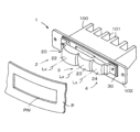
- Fig. 3 is a perspective view showing the schematic configuration of the projection device 1 of the embodiment, showing the left projection device 1 disposed at the front left part of the body of the automobile CAR shown in Fig. 1.
- the right projection device 1, not shown, has a symmetrical configuration.
- the projection device 1 shown in Fig. 3 has a heat dissipation fin 101 on the rear side to double as a heat sink, and is equipped with a horizontally elongated housing 100 with an open front side. Inside this housing 100, three projection units 2, 3, and 4, described below, are integrated and aligned in the vehicle width direction.
- the projection device 1 has a projection lens 20 attached to the front of the housing 100 with screws or the like, and this projection lens 20 is fixed to the front of the automobile CAR with bolts or the like on both sides of the front flange 102 of the housing 100.
- the projection lens 20 is exposed to the front side of the automobile CAR through an opening window PW opened in the front panel P of the vehicle, and the light emitted from this projection lens 20 makes it possible to project a light pattern OP.
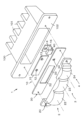
- FIG. 4 is a partially exploded perspective view of the main parts of the projection device 1
- FIG. 5 is a schematic plan view of the projection units 2, 3, and 4 housed within the housing 100. Note that these figures omit illustrations and explanations of the detailed configuration of the housing 100 and the specific support structure of the projection units 2, 3, and 4 disposed within the housing 100.
- the three projection units 2, 3, 4 are arranged side by side in the vehicle width direction inside the housing 100, and are configured as the far projection unit 2, which is located on the inside in the vehicle width direction (in this example, the left side in FIG. 4, the upper side in FIG. 5) and projects the far light pattern FOP, the central projection unit 3, which is located further outward in the vehicle width direction and projects the central light pattern COP, and the near projection unit 4, which is located on the outermost side in the vehicle width direction and projects the near light pattern NOP.
- the far projection unit 2 and the central projection unit 3 are configured as the far distance side projection units in the present invention
- the near projection unit 4 is configured as the near distance side projection unit in the present invention.
- Each projection unit 2, 3, 4 is equipped with a light source unit 10, a projection lens 20, and a shade 30, the details of which will be described later, and the near projection unit 4 further includes a primary lens 40.
- the far-field projection unit 2 includes a far-field light source section 12 that emits light to the light source section 10. It also includes a far-field projection lens 22 that projects the light emitted from the light source section 12 to the projection lens 20 onto the road surface as a light pattern. Furthermore, a shade 30 is disposed between the light source section 12 and the projection lens 22, and this shade 30 includes a far-field shade opening 32 that transmits light that contributes to the formation of the light pattern out of the light emitted from the light source section 12.
- the central projection unit 3 has a configuration substantially the same as that of the far-field projection unit 2, and is equipped with a central light source unit 13 that emits light to the light source unit 10. It also has a central projection lens 23 that projects the light emitted from the light source unit 13 to the projection lens 20 onto the road surface as a light pattern. Furthermore, a shade 30 is disposed between the light source unit 13 and the projection lens 23, and this shade 30 is provided with a central shade opening 33 that transmits light that contributes to the formation of the light pattern out of the light emitted from the light source unit 13.
- the near projection unit 4 includes a near light source section 14 that emits light to the light source section 10, and a near projection lens 24 that projects the light emitted from the near light source section 13 to the projection lens 20 as a light pattern onto the road surface.
- a primary lens 40 that focuses the light emitted from the near light source section 14 is provided between the near light source section 14 and the near projection lens 24, and a shade 30 is further disposed between the primary lens 40 and the near projection lens 24, and the shade 30 is provided with a near shade opening 34 that forms a pseudo light source of a light pattern with the light focused by the primary lens 40.
- the distant light source section 12 and the central light source section 13 are each composed of one light-emitting element, and here, each light-emitting element is composed of an LED (light-emitting diode) that emits the required color light, for example amber light.
- each light source section 12, 13 will be referred to as LED 12, 13, or distant LED 12 and central LED 13, respectively.
- Each LED 12, 13 has a rectangular light-emitting surface, and is mounted on a common light source board 15 in which the required electrical circuit is configured with this light-emitting surface facing forward.
- each LED 12, 13 is electrically connected to the lighting control section via the electrical circuit configured in the light source board 15, and emits light when the auxiliary lamp SL is turned on as a turn signal lamp.
- the light source section 14 is composed of an LED that emits amber light.
- this light source section 14 will be referred to as the LED 14 or the nearby LED 14.
- This nearby LED 14 has a rectangular light-emitting surface, and is mounted on a light source board 16 that is separate from the light source board 15, with this light-emitting surface facing forward.
- This nearby LED 14 is electrically connected to the lighting control section via an electrical circuit configured in the light source board 16, and emits light when the auxiliary lamp SL is turned on as a turn signal lamp.
- Each projection lens 22, 23, 24 of the far, center, and near projection units 2, 3, 4 is configured as a single projection lens 20.
- it is configured from a single integrally molded light-transmitting member such as transparent resin, and is formed in a form in which the far projection lens 22, center projection lens 23, and near projection lens 24 are aligned horizontally in this order from the inside to the outside in the vehicle width direction, and are set back in a stepped manner toward the rear along the optical axis Lx.
- Each projection lens 22, 23, 24 is configured as a spherical or aspherical single convex lens, but may also be configured as a biconvex lens or a meniscus convex lens. Also, it is formed as a roughly rectangular lens with the four periphery of a circular lens cut in an arc shape.
- the shade openings 32, 33 and 34 are formed in one shade 30.
- the shade 30 is composed of a single non-translucent horizontally elongated plate-shaped member, and a distant shade opening 32, a central shade opening 33 and a nearby shade opening 34 are provided corresponding to each of the projection units 2, 3 and 4.
- the distant shade opening 32 and the central shade opening 33 are formed as a single horizontally elongated rectangular opening, but each may be a separate opening.
- the nearby shade opening 34 is formed as a single square or rectangular opening, that is, as an opening with a shape corresponding to the light pattern to be projected.
- the far shade opening 32 and the central shade opening 33 are provided to transmit only the light that contributes to the projection of the light pattern among the light emitted from the far LED 12 and the central LED 13, respectively, and to block non-pattern light that does not contribute.
- they are configured to block light that is emitted from the light-emitting surface of each LED 12, 13, respectively, that does not enter the projection lenses 22, 23, or that enters the peripheral parts of the projection lenses 22, 23, and in particular, light that is above the projection lenses 22, 23 or that enters the upper edges.
- the near projection unit 4 is provided with a primary lens 40 that temporarily focuses the light emitted by the near LED 14 at a position near the near shade opening 34, and this primary lens 40 is supported on the front end of the light source board 16.
- This primary lens 40 forms an image of the light emitting surface of the near LED 14 at the position of the near shade opening 34, thereby forming a pseudo light source for emitting light with a rectangular light flux shape (beam shape) based on the opening shape of the near shade opening 34.
- each projection unit 2, 3, 4 The light source section 10 and primary lens 40 of each projection unit 2, 3, 4 are then housed within the housing 100.
- the projection lens 20 and shade 30, which are integrally provided in common to each projection unit 2, 3, 4, are fastened together to the opening flange 102 on the front surface of the housing 100 by a fastening means such as a screw, thereby forming the projection device 1 with the external configuration shown in FIG. 3.
- the far-field projection lens 22 is configured so that the far-field LED 12 is positioned on the focal plane on the light source side.
- the far-field LED 12 is positioned on the focal plane of the far-field projection lens 12 at a position displaced upward from the optical axis Lx by the required first dimension L1.
- the central projection lens 23 is configured as a lens with a shorter focal length than the far projection lens 22, and as shown in FIG. 6(b), the central LED 13 is disposed on the focal plane of the central projection lens 23 at a position displaced upward from the optical axis Lx by a second dimension L2 that is slightly longer than the first dimension L1.
- the near projection lens 24 is configured as a lens with a shorter focal length than the central projection lens 23, and the near shade opening 34 is located on its focal plane and above the optical axis Lx, as shown in FIG. 6(c).
- the primary lens 40 is configured as a lens with a focal length that focuses the amber light emitted from the near LED 14 onto the near shade opening 34.
- the projection device 1 for example, when the driving direction of the automobile CAR is changed, the auxiliary lamps SL are turned on (flashed) as turn signal lamps, and at the same time, the projection device 1 projects a light pattern. That is, the LEDs 12, 13, 14 of the projection units 2, 3, 4 emit light, and the light emitted from the LEDs 12, 13, 14 is projected by the projection lenses 22, 23, 24 into the light patterns FOP, COP, NOP shown in FIG. 2. Note that the illustrated light paths when the projection device 1 projects are shown simply for the purpose of explanation, and do not accurately represent the actual light paths.
- FIGs 5 and 6(a) in the far projection unit 2, the far LED 12 emits light, and the emitted amber light passes through the far shade opening 32 and is projected by the far projection lens 22 onto the road surface far ahead of the vehicle.
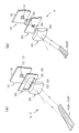
- Figure 7(a) is a schematic perspective view. That is, when the far LED 12 emits light, the light emitted from the rectangular light-emitting surface passes through the far shade opening 32 and is then projected by the far projection lens 22 onto the road surface in front of the vehicle, where it is projected onto the road surface as a rectangular far light pattern FOP equivalent to the shape of the light-emitting surface of the far LED 12.
- the projected far light pattern FOP is a long and narrow light pattern in the front-to-rear direction of the automobile CAR, as shown in FIG. 2(a).
- non-pattern light that does not contribute to the projection of the far light pattern FOP among the light emitted from the far LED 12 is blocked by the shade 30.
- the near LED 14 emits light, and the emitted amber light is focused by the primary lens 40 at a position near the near shade opening 34.
- the light is then transmitted through the near shade opening 34 to become a rectangular beam-shaped light beam, which is then projected by the near projection lens 24 onto the road surface in front of the vehicle as a near light pattern NOP.
- this near light pattern NOP is closer to the vehicle CAR than the central light pattern COP, and is a light pattern that is elongated in the front-to-rear direction.
- non-pattern light that does not contribute to the projection of the near light pattern NOP is blocked by the shade 30.
- the light irradiation from the turn signal lamps SL and the light pattern OP from the projection device 1 can indicate the direction in which the vehicle is traveling, thereby improving traffic safety.
- the far light pattern FOP far ahead of the vehicle CAR it is possible to alert other vehicles and pedestrians that are far ahead, thereby improving safety.
- non-pattern light that does not contribute to the projection of the light pattern is emitted from each projection lens 22, 23, 24 of each projection unit 2, 3, 4, and when this non-pattern light is emitted from the projection lenses 22, 23, 24 to an upper area at an angle equal to or greater than the required angle, as shown in dotted line in Figure 2(b), this non-pattern light enters the illumination area of the auxiliary lamp SL, i.e., the turn signal lamp, which is disposed above the projection device 1, and becomes glare light LG.
- the auxiliary lamp SL i.e., the turn signal lamp
- the shape and dimensions of the shade openings 32, 33 are appropriately set so that the light emitted from the respective LEDs 12, 13 that is directed upward is blocked by the shade 30.
- the non-pattern light (thick dashed line) LG directed upward in the far projection unit 2 is blocked by the shade 30. This prevents the non-pattern light from becoming glare light LG.
- the near projection unit 4 only the light that projects the near light pattern NOP passes through the shade opening 34, and the non-pattern light is blocked by the shade 30, so glare light is hardly generated.
- Each projection lens 22, 23, 24 of each projection unit 2, 3, 4 is shaped like a circular lens with the four peripheries cut away, reducing the area of the lens surface, i.e., the light exit surface for projecting the light pattern. This reduces the amount of light that passes through the lens surface of each projection lens 22, 23, 24 and is directed left and right and up and down.
- the amount of light that passes through the upper edge region of the lens surface and is directed upwards is reduced, and glare light is suppressed.
- the lower edge and left and right edges non-pattern light that is directed upwards from these edge regions can be suppressed, and glare light is suppressed. Note that there is less glare light in the downward and left and right horizontal directions, so the shade is less likely to block light in these directions.
- the sides, including the top sides, of the projection lenses 22, 23, and 24 are cut off to reduce the area of the lens surface of the projection lenses, the amount of light projected from each projection lens 22, 23, and 24 is reduced, and the brightness of the projected light pattern may decrease.
- the decrease in brightness of each light pattern is noticeable in the far projection unit 2 and the central projection unit 3, where the projection distance of the light pattern is relatively long.
- the far projection unit 2 and the central projection unit 3 use a projection method in which the light emitted from the LEDs 12 and 13 is directly incident on each projection lens 22 and 23, respectively, and a light pattern based on the surface shape of the light-emitting surface of each LED 12 and 13 is projected. That is, a direct projection method is used in which the rectangular shape of the light-emitting surface of the LEDs 12 and 13 is projected as a light pattern.
- the reduction in brightness of the light pattern due to light absorption and diffuse reflection when passing through the primary lens 40 is suppressed, and the reduction in brightness due to the reduction in the area of the lens surface can be prevented.
- the direct projection method used in the far projection unit 2 and the central projection unit 3 tends to result in lower sharpness at the edges of the projected light pattern compared to the indirect projection method of the near projection unit 4.
- the sharpness of the light pattern is originally lower compared to the near light pattern NOP (see FIG. 7(b)), and even if a direct projection method is used, the decrease in sharpness of the light pattern is not noticeable.
- the projection distance of the light pattern is short and the sharpness is easily noticeable, so by adopting an indirect projection method using the primary lens 40 and the shade opening 34, it is possible to project a light pattern with high sharpness.
- non-pattern light is blocked by the shade 30 built into the housing 100, and the emission of non-pattern light from the projection lenses 22, 23 is suppressed, so glare light can be effectively prevented.
- a direct projection method a decrease in brightness of the light pattern can be prevented.
- glare light and a decrease in brightness of the light pattern are not so much of a problem, so by adopting an indirect projection method, the pattern quality of the light pattern can be improved.
- the light source section 10, the shade 30, and the projection lens 20 of each projection unit 2, 3, and 4 may be configured as separate components.
- the projection lens 20 is configured as a separate component, glare light is suppressed by reducing the area of the lens surface of the projection lens, particularly in projection units that employ a direct projection method.
- the projection device 1 may be disposed to the side of the front lamp FL.
- the area of the lens surface of the projection lens can be reduced by reducing the dimensions in the left-right direction in particular.
- one side of the projection lens on the side where the front lamp is located can be removed.
- the shade can also be configured to block non-pattern light in the left-right direction.
- the lens surface in the central projection unit 3 may be configured as an indirect projection type projection unit, similar to the near projection unit 4. That is, the unit is configured with a shade opening having a shape corresponding to the light pattern in the shade, and a primary lens that focuses the light from the light source onto the shade opening. Also, in the near projection unit 4, the primary lens may be configured as a reflector, so long as it has the function of focusing light to form a pseudo light source.
- the present invention can be applied to a projection device that projects light patterns onto at least two positions on the relatively close and far side.
- the far-distance projection unit that projects the light pattern onto the far-distance side is configured as a projection unit using a direct projection method
- the near-distance projection unit that projects the light pattern onto the near-distance side is configured as a projection unit using an indirect projection method.
- the present invention is not limited to projection devices for projecting a light pattern onto the road surface in front of the vehicle as described in the embodiment, but can also be applied to projection devices that project a light pattern toward the rear or side of the vehicle. It can also be applied when the projection device is disposed to the side of the lamp.
- Projection device 2 Far-field projection unit (far-distance projection unit) 3. Central projection unit (far-distance projection unit) 4. Near-field projection unit (near-field projection unit) 10 (12, 13, 14) Light source unit (light emitting element: LED) 15, 16 Light source substrate 20 (22, 23, 24) Projection lens 30 Shade 32, 33, 34 Shade opening 40 Primary lens 100 Housing CAR Automobile (vehicle) OP light pattern FOP far-field light pattern (far-field light pattern) COP Central light pattern (far-distance light pattern) NOP Near-field light pattern (near-field light pattern) SL Auxiliary lamp (turn signal lamp) LG Glare Light
Landscapes
- Engineering & Computer Science (AREA)
- General Engineering & Computer Science (AREA)
- Mechanical Engineering (AREA)
- Physics & Mathematics (AREA)
- Microelectronics & Electronic Packaging (AREA)
- Optics & Photonics (AREA)
- Non-Portable Lighting Devices Or Systems Thereof (AREA)
- Lighting Device Outwards From Vehicle And Optical Signal (AREA)
Abstract
車両の補助ランプの照射光に対するグレアを防止する一方で、路面に投影する光パターンの明るさの低下を抑制した投影装置を提供する。車両に搭載され、周囲の路面に光パターンを投影する投影装置(1)であり、相対的に遠距離の位置に所定の遠距離側光パターンを投影する遠距離側投影ユニット(2,3)と、相対的に近距離の位置に所定の近距離側光パターンを投影する近距離側投影ユニット(4)を備える。遠距離側投影ユニット(2,3)はLED(12,13)の発光面の面形状を投影レンズ(22,23)により光パターン(FOP,COP)として投影する。近距離側投影ユニット(4)はLED(14)から出射された光を遮光するシェード(30)に開口されたシェード開口(34)の開口形状を投影レンズ(24)により光パターン(NOP)として投影する。
Description
本発明は車両に搭載されて道路の路面に所要の光パターンを投影描画するのに好適な投影装置に関する。
近年、自動車の走行に伴う交通安全を図る目的で、自動車の周囲の路面に光パターンを投影し、他車両や歩行者に対して注意喚起力を高めようとする技術が提案されている。このような光パターンを投影する投影装置として、例えば、特許文献1には、光源としての発光素子の前側に所要の形状をしたシェード開口を配置し、このシェード開口で構成される光パターンを投影レンズにより投影する技術が提案されている。また、この特許文献1には、複数の光源と複数のシェード開口を配置することにより、1つの投影装置により複数の光パターンを投影する技術も提案されている。
この種の投影装置は、図1の投影装置1で例示するように、自動車CARのフロントランプFLよりも下側の位置に配設されることが多い。この例では、投影装置1は自動車CARのフロントバンパーの近傍位置に配設され、自動車の前方の路面に光パターンOPを投影するように構成される。自動車CARの前方の路面に走行方向を示す光パターンOPを投影することにより、自動車CARの前方ないし前側に存在する他車両や歩行者等に対して自動車の走行方向を報知し、交通安全に寄与することになる。例えば、フロントランプFLの一部を構成しているターンシグナルランプ(補助ランプSL)を点灯(点滅)する際に、これと同期して光パターンOPを投影することで、ターンシグナルランプの光照射と、投影装置1による光パターンOPとで自動車の走行方向を表示することができ交通の安全性を高めることができるようになる。
このようにランプと同期して光パターンを投影する場合において、投影装置から出射される光の一部がランプの光照射領域に進入し、この進入した光がグレア光としてランプの正常な光照射に悪影響を与えることがある。詳細については後述するが、図1の例では、投影装置1から投射された光のうち上方に向けられた一部の光が、上側に配置されているターンシグナルランプSLの光照射領域にグレア光LGとして進入される。
このグレア光を防止するために、投影装置には、投影レンズから投射される光のうち、光パターンの投影に寄与することがない光(非パターン光)、特にフロントランプFLが配置されている上方への光を遮光するためのフードやシェード等の遮光手段を配設することが考えられる。あるいは、投影レンズの形状を特異な形状にし、あるいは投影レンズのレンズ面の面積を低減する等して、投射光のうち上方に向けられる光を抑制することも考えられる。しかし、いずれの場合においても、投射光の一部を遮光することになるため、投影される光パターンの光量が低減され、光パターンの明るさが低下する要因になる。
本発明の目的は、ランプの照射光に対するグレアを防止する一方で、投影する光パターンの明るさの低下を抑制した投影装置を提供する。
本発明の投影装置は、車両に搭載され、周囲の路面に光パターンを投影する投影装置であって、投影装置は、相対的に遠距離の位置に所定の遠距離側光パターンを投影する遠距離側投影ユニットと、相対的に近距離の位置に所定の近距離側光パターンを投影する近距離側投影ユニットを備える。また、遠距離側投影ユニットは光源部の発光面の面形状を光パターンとして投影する投影ユニットであり、近距離側投影ユニットは光源部から出射された光を遮光するシェードに開口されたシェード開口の開口形状を光パターンとして投影する投影ユニットである。
本発明において、遠距離側投影ユニットは、例えば、所要の形状をした発光面を有する光源部と、発光面から出射された光を投影する投影レンズを備えており、発光面は投影レンズの焦点面上に配置され、投影レンズは発光面の面形状を光パターンとして投影する構成とされる。また、遠距離側投影ユニットは、投影する光パターンに寄与しない非パターン光を遮光するシェードを備えることが好ましい。
本発明において、近距離側投影ユニットは、例えば、光を出射する光源部と、光源部の光を集光するプライマリレンズと、プライマリレンズで集光された光を透過させるシェード開口を有するシェードと、シェード開口を透過した光を投影する投影レンズを備え、投影レンズはシェード開口の開口形状を光パターンとして投影する構成とされる。
本発明によれば、遠距離側投影ユニットは光源部の発光面の面形状を光パターンとして投影する投影ユニットであるので、グレア光を防止するためにシェード等により非パターン光を遮光しても投影する光パターンの明るさの低下が防止できる。また、グレア光が少ない近距離側投影ユニットは光源部から出射された光を遮光するシェードに開口されたシェード開口の開口形状を光パターンとして投影する投影ユニットであるので、明るくかつ鮮鋭な光パターンの投影が実現できる。
次に、本発明の実施の形態について図面を参照して説明する。この実施形態では、図1に示したように、自動車CARの車体前部に配設されるフロントランプFLの下方位置に投影装置1が配設されている。図1には自動車CARの前部のみを図示しているが、フロントランプFLは自動車CARの左右に配設されており、これに対応して投影装置1も自動車CARの左右に配設されている。フロントランプFLは、ヘッドランプHLと、クリアランスランプとターンシグナルランプとして兼用される補助ランプSLが一体に構成された複合型のランプとして構成されている。
左右の投影装置1は自動車CARの左右同じ側のフロントランプFLの点灯に同期して所要の光パターンを投影するように構成されており、ここでは左右のいずれかの補助ランプSLがターンシグナルランプとして点滅状態に点灯されたときに、これに対応する側の投影装置1が同期して自動車CARの前方の路面に自動車の前後方向に沿った細長い長方形の光パターンOPを投影するように構成されている。
すなわち、図2(a)の模式平面図と、図2(b)の模式側面図に示すように、左右の各投影装置1は、自動車CARの直進方向に対して幾分車幅方向の外側斜め前方に向けて延びる仮想直線(破線)に沿って長方形ないしは帯状をした光パターンOPを投影する構成とされている。この例では、左右の各投影装置1は、仮想直線に沿って自動車CARの直前の近傍位置と、これよりも幾分遠い中央位置と、自動車CARから最も遠い遠方位置にそれぞれ光パターンとして近傍光パターンNOP、中央光パターンCOP、遠方光パターンFOPを投影する。自動車CARから近傍光パターンNOP、中央光パターンCOP、遠方光パターンFOPまでの各距離は適宜に設定されるが、例えば、遠方光パターンFOPまでの距離は4m程度とされる。
図3は実施形態の投影装置1の概略構成を示す斜視図であり、図1に示した自動車CARの車体左前部に配設された左側の投影装置1を示している。図示を省略した右側の投影装置1は左右が対称の構成である。図3に示す投影装置1は、ヒートシンクを兼ねるために後面側に放熱フィン101を有し、前面側が開口された水平方向に横長のハウジング100を備えている。このハウジング100の内部に後述する3つの投影ユニット2,3,4が車幅方向に並んで一体的に組み込まれている。
図3に示すように、投影装置1はハウジング100の前面に投影レンズ20がネジ等により取り付けられており、この投影レンズ20はハウジング100の前面フランジ102の両側部位においてボルト等により自動車CARの車体前部に固定される。また、固定されたときには投影レンズ20が車体前部パネルPに開口された開口窓PWを通して自動車CARの前面側に露呈され、この投影レンズ20から出射される光により光パターンOPの投影が可能とされている。
図4は投影装置1の要部の部分分解斜視図、図5はハウジング100に内装された各投影ユニット2,3,4の概略の平面図である。なお、これらの図においては、ハウジング100の詳細な構成と、このハウジング100内に配設される投影ユニット2,3,4の具体的な支持構造についての図示及びその説明は省略している。
前記した3つの投影ユニット2,3,4はハウジング100内において車幅方向に並んで配設されており、車幅方向の内側(この例では図4の左側,図5の上側)に配置されて遠方光パターンFOPを投影する遠方投影ユニット2と、これよりも車幅方向の外側寄りに配置されて中央光パターンCOPを投影する中央投影ユニット3と、最も車幅方向の外側に配置されて近傍光パターンNOPを投影する近傍投影ユニット4として構成されている。これらの投影ユニット2,3,4は、遠方投影ユニット2と中央投影ユニット3が本発明における遠距離側投影ユニットとして構成され、近傍投影ユニット4が本発明における近距離側投影ユニットとして構成されている。各投影ユニット2,3,4は、詳細については後述するが、それぞれ光源部10、投影レンズ20、シェード30を備えており、近傍投影ユニット4はさらにプライマリレンズ40を備えている。
遠方投影ユニット2は、光源部10に光を出射する遠方光源部12を備えている。また、投影レンズ20に光源部12から出射された光を光パターンとして路面に投影する遠方投影レンズ22を備えている。さらに、光源部12と投影レンズ22との間にシェード30が配置され、このシェード30には、光源部12から出射された光のうち、光パターンの形成に寄与する光を透過する遠方シェード開口32が設けられている。
中央投影ユニット3は遠方投影ユニット2と略同じ構成であり、光源部10に光を出射する中央光源部13を備えている。また、投影レンズ20に光源部13から出射された光を光パターンとして路面に投影する中央投影レンズ23を備えている。さらに、光源部13と投影レンズ23との間にシェード30が配置されており、このシェード30には光源部13から出射された光のうち、光パターンの形成に寄与する光を透過する中央シェード開口33が設けられている。
近傍投影ユニット4は、光源部10に光を出射する近傍光源部14を備え、投影レンズ20に近傍光源部13から出射された光を光パターンとして路面に投影する近傍投影レンズ24を備えている。また、近傍光源部14と近傍投影レンズ24との間に、近傍光源部14から出射された光を集光するプライマリレンズ40を備え、さらにプライマリレンズ40と近傍投影レンズ24との間にシェード30が配置され、このシェード30にはプライマリレンズ40で集光された光で光パターンの疑似光源を形成する近傍シェード開口34が設けられている。
遠方投影ユニット2と中央投影ユニット3において、遠方光源部12と中央光源部13はそれぞれ1つの発光素子で構成されており、ここでは各発光素子は所要の色光、例えばアンバー色光を発光するLED(発光ダイオード)で構成されている。以降において各光源部12,13をそれぞれLED12,13、あるいは遠方LED12及び中央LED13と称する。各LED12,13は矩形をした発光面を有しており、この発光面を前方に向けた状態で所要の電気回路が構成された共通の光源基板15に搭載されている。図示は省略するが、各LED12,13は光源基板15に構成されている電気回路を介して点灯制御部に電気接続され、補助ランプSLがターンシグナルランプとして点灯されたときに発光される。
近傍投影ユニット4において、光源部14はアンバー色光を発光するLEDで構成されている。以降においてこの光源部14をLED14あるいは近傍LED14と称する。この近傍LED14は矩形をした発光面を有しており、この発光面を前方に向けて状態で前記光源基板15とは別体の光源基板16に搭載されている。この近傍LED14は光源基板16に構成されている電気回路を介して点灯制御部に電気接続され、補助ランプSLがターンシグナルランプとして点灯されたときに発光される。
遠方、中央、近傍の各投影ユニット2,3,4の各投影レンズ22,23,24は1つの投影レンズ20として構成されている。例えば、1つの一体成形された透明樹脂等の透光性部材で構成されており、車幅方向の内側から外側に向けて遠方投影レンズ22、中央投影レンズ23、及び近傍投影レンズ24がこの順序で水平方向に並んだ状態で、かつ光軸Lxに沿った後方に向けて階段状に後退された形態に形成されている。各投影レンズ22,23,24は球面又は非球面の片凸レンズで構成されているが、両凸レンズあるいはメニスカス凸レンズで構成されてもよい。また、円形をしたレンズの四周辺を円弧状に切除した略矩形のレンズに形成されている。
遠方、中央、近傍の各投影ユニット2,3,4において、各シェード開口32,33,34は1つのシェード30に形成されている。例えば、シェード30は1枚の非透光性の横長の板状部材で構成されており、各投影ユニット2,3,4に対応して遠方シェード開口32、中央シェード開口33、及び近傍シェード開口34が設けられている。遠方シェード開口32と中央シェード開口33は横長の矩形をした1つの開口として形成されているが、それぞれ個別の開口であってもよい。近傍シェード開口34は正方形または長方形をした1つの開口として、すなわち投影する光パターンに対応した形状の開口として形成されている。
遠方シェード開口32と中央シェード開口33は、それぞれ遠方LED12と中央LED13から出射された光のうち、光パターンの投影に寄与する光のみを透過し、寄与しない非パターン光を遮光するために設けられる。すなわち、各LED12,13の発光面からそれぞれ出射された光のうち、投影レンズ22,23に入射されない光、あるいは投影レンズ22,23の周辺部に入射される光、特に投影レンズ22,23の上方に外れた光や上辺部に入射される光を遮光する構成とされている。
さらに、近傍投影ユニット4においては、近傍LED14で発光された光を近傍シェード開口34の近傍位置に一旦集光するプライマリレンズ40を備えており、このプライマリレンズ40は光源基板16の前端部に支持されている。このプライマリレンズ40は近傍シェード開口34の位置において近傍LED14の発光面を結像することにより、近傍シェード開口34の開口形状に基づいた矩形の光束形状(ビーム形状)の光を出射するための疑似光源を形成する。
その上で、各投影ユニット2,3,4の光源部10とプライマリレンズ40はハウジング100に内装される。また、各投影ユニット2,3,4に共通して一体に設けられた投影レンズ20とシェード30はハウジング100の前面の開口フランジ102にネジ等の固定手段により共締め状態に固定され、これにより図3に示した外観構成の投影装置1が構成される。
このように構成された投影装置1においては、図6(a)の概略側面図に示すように、遠方投影レンズ22は光源部側の焦点面上に遠方LED12が位置されるように構成される。すなわち、遠方投影レンズ12の焦点面上で光軸Lxよりも所要の第1の寸法L1だけ上方に変位された位置に遠方LED12が配置されている。
一方、中央投影レンズ23は遠方投影レンズ22よりも焦点距離が短いレンズとして構成されており、図6(b)に概略図示するように、中央投影レンズ23の焦点面上で、かつ第1寸法L1よりも幾分だけ長い第2寸法L2だけ光軸Lxよりも上方に変位された位置に中央LED13が配置される。
近傍投影レンズ24は中央投影レンズ23よりも焦点距離が短いレンズとして構成されており、図6(c)に概略図示するように、その焦点面上でかつ光軸Lxよりも上側の位置に近傍シェード開口34が配置されている。また、プライマリレンズ40は、近傍LED14から出射されたアンバー色光を近傍シェード開口34に集光する焦点距離のレンズで構成されている。
以上の構成の実施形態の投影装置1によれば、例えば自動車CARの走行方向が変更されるときに、補助ランプSLがターンシグナルランプとして点灯(点滅)されると、これと同時に投影装置1による光パターンの投影が行われる。すなわち、各投影ユニット2,3,4の各LED12,13,14が発光され、各LED12,13,14から出射された光は各投影レンズ22,23,24により、図2に示した光パターンFOP,COP,NOPの投影が行われる。なお、投影装置1が投影を行う際の図示の光路は説明のために簡略に示したものであり、実際の光路を正確に示すものではない。
遠方投影ユニット2は、図5及び図6(a)のように、遠方LED12が発光され、出射されたアンバー色光は遠方シェード開口32を透過され、遠方投影レンズ22により自動車の遠前方の路面に投射される。図7(a)はその模式的な斜視図である。すなわち、遠方LED12が発光されたときに矩形をした発光面から出射された光は、遠方シェード開口32を透過した後、遠方投影レンズ22により自動車の前方の路面に向けて投射され、当該路面に遠方LED12の発光面の形状と等価な矩形の遠方光パターンFOPとして投影される。
投射される光は路面に対して斜め方向から投射されるので、投影される遠方光パターンFOPは、図2(a)にも示したように、自動車CARの前後方向に細長い光パターンとされる。また、遠方LED12から出射された光のうち、遠方光パターンFOPの投影に寄与しない非パターン光はシェード30により遮光される。
同様に、中央投影ユニット3は、図5及び図6(b)のように、中央LED13が発光されたときに矩形をした発光面から出射された光は、中央シェード開口33を透過した後、中央投影レンズ23により自動車の前方の路面に向けて投射され、当該路面に中央LED13の発光面の形状と等価な矩形の中央光パターンCOPとして投影される。この中央光パターンCOPは、図2(a)に示したように、遠方光パターンFOPよりも自動車CARに近い位置であり、前後方向に細長い光パターンとされる。また、中央LED13から出射された光のうち、中央光パターンCOPの投影に寄与しない非パターン光はシェード30により遮光される。この投影形態は図7(a)に示した遠方投影ユニット2の投影形態と同様である。
近傍投影ユニット4は、図5及び図6(c)のように、近傍LED14が発光され、出射されたアンバー色光は、プライマリレンズ40により近傍シェード開口34の近傍位置に集光される。そして、近傍シェード開口34を透過されて矩形のビーム形状の光ビームとされた上で、近傍投影レンズ24により自動車の前方の路面に近傍光パターンNOPとして投影される。この近傍光パターンNOPは、図2(a)のように、中央光パターンCOPよりも自動車CARに近い位置であり、前後方向に細長い光パターンとされる。また、近傍LEDから出射された光のうち、近傍光パターンNOPの投影に寄与しない非パターン光はシェード30により遮光される。
このように、ターンシグナルランプSLの点灯(点滅)と同期して光パターンOPを投影することで、ターンシグナルランプSLでの光照射と、投影装置1による光パターンOPとで自動車の走行方向を表示することができ交通の安全性を高めることができるようになる。特に、自動車CARの遠前方に遠方光パターンFOPが投影されることにより、遠前方に存在する他車両や歩行者に注意を喚起することができ、安全性を高めることができる。
この光パターンの投影に際し、各投影ユニット2,3,4の各投影レンズ22,23,24から光パターンの投影に寄与しない非パターン光が出射され、この非パターン光が投影レンズ22,23,24から所要の角度以上の上方領域が出射されると、図2(b)に点描しているように、この非パターン光は、投影装置1の上方位置に配設されている補助ランプSL、すなわちターンシグナルランプの照射光領域に進入してグレア光LGになる。
特に、この投影装置1では、投影光が相対的に上方に向けられている遠方投影ユニット2と中央投影ユニット3においてグレア光が生じ易くなる。そこで、遠方投影ユニット2と中央投影ユニット3においては、シェード開口32,33の形状、寸法を適切に設定することにより、それぞれのLED12,13から出射された光のうち上方に向けられる光をシェード30により遮光している。図6(a)では遠方投影ユニット2における上方に向けられた非パターン光(太破線)LGをシェード30により遮光している。これにより非パターン光がグレア光LGとなることが抑制される。一方で、近傍投影ユニット4においては、シェード開口34は近傍光パターンNOPを投影する光のみが透過され、非パターン光はシェード30によって遮光されるため、グレア光が発生することは殆どない。
各投影ユニット2,3,4の各投影レンズ22,23,24は、円形レンズの四周辺が切除された形状とされ、そのレンズ面、すなわち光パターンを投影するための光の出射面の面積が低減されている。これにより、各投影レンズ22,23,24のレンズ面を透過して左右、上下に向けられる光が低減される。特に、レンズ面の上辺部を切除して投影レンズの上下方向の寸法を低減していることにより、レンズ面の上辺部領域を透過して上方に向けられる光が低減され、グレア光が抑制される。また、下辺部と左右辺部が切除されることにより、これらの辺部領域から上方に向けられる非パターン光を抑制することでき、グレア光が抑制される。なお、下方向及び左右水平方向については、グレア光の発生が少ないので、これらの方向についてはシェードによる遮光は抑制されている。
投影レンズ22,23,24の上辺部を含む各辺部が切除されて投影レンズのレンズ面の面積が低減されると、各投影レンズ22,23,24から投射される光量が低下され、投影される光パターンの明るさが低下されることがある。特に、光パターンの投影距離が相対的に大きな遠方投影ユニット2や中央投影ユニット3において各光パターンにおける明るさの低下が顕著になる。
実施形態では、遠方投影ユニット2と中央投影ユニット3においては、それぞれLED12,13から出射された光をそのまま、すなわち直接に各投影レンズ22,23に入射させ、各LED12,13の発光面の面形状に基づく光パターンの投影を行う投影方式を用いている。すなわち、LED12,13の発光面の矩形形状を光パターンとして投影する直接投影方式を用いている。したがって、近傍投影ユニット4のように、LED14の光をプライマリレンズ40で結像したLEDの疑似光源によりシェード開口34の形状に対応した光パターンを投影する間接投影方式に比較すると、プライマリレンズ40を透過する際の光吸収や乱反射等による光パターンの明るさの低下が抑制され、レンズ面の面積低減による明るさの低下が防止できる。
なお、遠方投影ユニット2と中央投影ユニット3で用いている直接投影方式は、近傍投影ユニット4の間接投影方式に比較すると、投影する光パターンのエッジ部における鮮鋭度が低くなり易い。しかし、遠方光パターンFOPや中央光パターンCOPは投影距離が長いため、近傍光パターンNOP(図7(b)参照)に比較して元々光パターンの鮮鋭度は低く、直接投影方式を用いても光パターンの鮮鋭度の低下は目立たない。近傍投影ユニット4においては、光パターンの投影距離が短く、鮮鋭度が目立ち易いので、プライマリレンズ40とシェード開口34を用いた間接投影方式を採用することにより、鮮鋭度の高い光パターンの投影が可能となる。
以上のように、実施形態の投影装置1においては、遠方投影ユニット2と中央投影ユニット3においては、ハウジング100に内装されているシェード30により非パターン光が遮光され、また投影レンズ22,23からの非パターン光の出射が抑制されているので、グレア光を効果的に防止できる。その一方で、直接投影方式を採用することにより光パターンの明るさの低下が防止できる。一方、近傍投影ユニット4においては、グレア光や光パターンの明るさの低下はそれほど問題とされないので、間接投影方式を採用することにより光パターンのパターン品質を高めることができる。
本発明において、各投影ユニット2,3,4の光源部10、シェード30、及び投影レンズ20はそれぞれ別体な部品として構成されてもよい。投影レンズ20が別体に構成された場合には、特に直接投影方式を採用している投影ユニットにおける投影レンズのレンズ面の面積を小さくすることによりグレア光が抑制される。
投影装置1はフロントランプFLの側方に配設されてもよい。この場合においては、投影レンズのレンズ面の面積を低減する際には、特に左右方向の寸法を小さくすればよい。例えば、投影レンズのフロントランプが存在する側の一辺部を切除すればよい。また、シェードは左右方向の非パターン光を遮光するように構成すればよい。
ここで、例えば、中央投影ユニット3において、レンズ面の面積を低減しても光パターンの明るさの低下が問題にならない場合には、近傍投影ユニット4と同様に、間接投影方式の投影ユニットとして構成されてもよい。すなわち、シェードに光パターンに対応した形状のシェード開口を設けるとともに光源の光をシェード開口に集光させるプライマリレンズを用いたユニット構成とする。また、近傍投影ユニット4において、プライマリレンズは、光を集光して疑似光源を形成する機能を備えていれば、リフレクタで構成されてもよい。
以上説明した実施形態においては、遠方光パターン、中央光パターン、近傍光パターンの3つの異なる位置に光パターンを投影する例を示したが、相対的に近距離側と遠距離側の少なくとも2つの位置に光パターンを投影する投影装置に適用できる。すなわち、遠距離側に光パターンを投影する遠距離側投影ユニットが直接投影方式の投影ユニットとして構成され、近距離側に光パターンを投影する近距離側投影ユニットが間接投影方式の投影ユニットとして構成される。
本発明は、実施形態に記載したように車両の前方の路面に光パターンを投影するための投影装置に限られるものではなく、車両の後方あるいは側方に向けて光パターンを投影する投影装置についても本発明が適用される。また、投影装置がランプの側方に配設されている場合においても適用できる。
本国際出願は、2023年7月5日に出願された日本国特許出願である特願2023-110375号に基づく優先権を主張するものであり、当該日本国特許出願である特願2023-110375号の全内容は、本国際出願に援用される。
本発明の特定の実施の形態についての上記説明は、例示を目的として提示したものである。それらは、網羅的であったり、記載した形態そのままに本発明を制限したりすることを意図したものではない。数多くの変形や変更が、上記の記載内容に照らして可能であることは当業者に自明である。
1 投影装置
2 遠方投影ユニット(遠距離側投影ユニット)
3 中央投影ユニット(遠距離側投影ユニット)
4 近傍投影ユニット(近距離側投影ユニット)
10(12,13,14) 光源部(発光素子:LED)
15,16 光源基板
20(22,23,24) 投影レンズ
30 シェード
32,33,34 シェード開口
40 プライマリレンズ
100 ハウジング
CAR 自動車(車両)
OP 光パターン
FOP 遠方光パターン(遠距離側光パターン)
COP 中央光パターン(遠距離側光パターン)
NOP 近傍光パターン(近距離側光パターン)
SL 補助ランプ(ターンシグナルランプ)
LG グレア光
2 遠方投影ユニット(遠距離側投影ユニット)
3 中央投影ユニット(遠距離側投影ユニット)
4 近傍投影ユニット(近距離側投影ユニット)
10(12,13,14) 光源部(発光素子:LED)
15,16 光源基板
20(22,23,24) 投影レンズ
30 シェード
32,33,34 シェード開口
40 プライマリレンズ
100 ハウジング
CAR 自動車(車両)
OP 光パターン
FOP 遠方光パターン(遠距離側光パターン)
COP 中央光パターン(遠距離側光パターン)
NOP 近傍光パターン(近距離側光パターン)
SL 補助ランプ(ターンシグナルランプ)
LG グレア光
Claims (9)
- 車両に搭載され、周囲の路面に光パターンを投影する投影装置であって、前記投影装置は、相対的に遠距離の位置に所定の遠距離側光パターンを投影する遠距離側投影ユニットと、相対的に近距離の位置に所定の近距離側光パターンを投影する近距離側投影ユニットを備えており、遠距離側投影ユニットは光源部の発光面の面形状を光パターンとして投影する投影ユニットであり、近距離側投影ユニットは光源部から出射された光を遮光するシェードに開口されたシェード開口の開口形状を光パターンとして投影する投影ユニットであることを特徴とする投影装置。
- 前記遠距離側投影ユニットは、所要の形状をした発光面を有する光源部と、前記発光面から出射された光を投影する投影レンズを備え、前記発光面は前記投影レンズの焦点面上に配置され、前記投影レンズは前記発光面の面形状を光パターンとして投影する請求項1に記載の投影装置。
- 前記遠距離側投影ユニットは、投影する光パターンに寄与しない非パターン光を遮光するシェードを備える請求項2に記載の投影装置。
- 前記近距離側投影ユニットは、光を出射する光源部と、前記光源部の光を集光するプライマリレンズと、前記プライマリレンズで集光された光を透過させるシェード開口を有するシェードと、前記シェード開口を透過した光を投影する投影レンズを備え、前記投影レンズは前記シェード開口の開口形状を光パターンとして投影する請求項1に記載の投影装置。
- 前記投影装置は、前記車両に搭載されて所定の光を照射するランプの下方位置に配設され、当該ランプの光照射と同期して光パターンを投影する請求項1ないし4のいずれかに記載の投影装置。
- 前記ランプは車両のターンシグナルランプを含む補助ランプである請求項5に記載の投影装置。
- 前記投影レンズは、円形をしたレンズ面の上辺部が切除されている請求項5に記載の投影装置。
- 前記遠距離側投影ユニットは、車両の最も遠方に遠方光パターンを投影する遠方投影ユニットと、この遠方光パターンよりも車両の近傍に中央光パターンを投影する中央投影ユニットで構成され、前記近距離側投影ユニットは前記中央光パターンよりも車両の近傍に近傍光パターンを投影する近傍投影ユニットとして構成される請求項1に記載の投影装置。
- 前記遠距離側投影ユニットと近距離側投影ユニットは、各投影レンズ及びシェードが一体に形成されている請求項8に記載の投影装置。
Priority Applications (1)
| Application Number | Priority Date | Filing Date | Title |
|---|---|---|---|
| CN202480040148.XA CN121311385A (zh) | 2023-07-05 | 2024-07-01 | 投影装置 |
Applications Claiming Priority (2)
| Application Number | Priority Date | Filing Date | Title |
|---|---|---|---|
| JP2023110375A JP2025008319A (ja) | 2023-07-05 | 2023-07-05 | 投影装置 |
| JP2023-110375 | 2023-07-05 |
Publications (1)
| Publication Number | Publication Date |
|---|---|
| WO2025009494A1 true WO2025009494A1 (ja) | 2025-01-09 |
Family
ID=94172178
Family Applications (1)
| Application Number | Title | Priority Date | Filing Date |
|---|---|---|---|
| PCT/JP2024/023714 Ceased WO2025009494A1 (ja) | 2023-07-05 | 2024-07-01 | 投影装置 |
Country Status (3)
| Country | Link |
|---|---|
| JP (1) | JP2025008319A (ja) |
| CN (1) | CN121311385A (ja) |
| WO (1) | WO2025009494A1 (ja) |
Citations (8)
| Publication number | Priority date | Publication date | Assignee | Title |
|---|---|---|---|---|
| JP2019215958A (ja) * | 2018-06-11 | 2019-12-19 | 市光工業株式会社 | 車両用灯具 |
| JP2020017488A (ja) * | 2018-07-27 | 2020-01-30 | マクセル株式会社 | 路面映像投射装置及び車両用灯具 |
| WO2022019231A1 (ja) * | 2020-07-20 | 2022-01-27 | 株式会社小糸製作所 | 画像投影装置 |
| JP2022052186A (ja) * | 2020-09-23 | 2022-04-04 | 株式会社小糸製作所 | 車両用灯具 |
| WO2022168543A1 (ja) * | 2021-02-03 | 2022-08-11 | 株式会社小糸製作所 | 路面描画装置 |
| WO2023013442A1 (ja) * | 2021-08-02 | 2023-02-09 | 株式会社小糸製作所 | 車両の表示装置 |
| JP2023028932A (ja) | 2021-08-20 | 2023-03-03 | 株式会社小糸製作所 | 描画用灯具 |
| JP2023110375A (ja) | 2022-01-28 | 2023-08-09 | 日本車輌製造株式会社 | コンクリートの再養生方法 |
-
2023
- 2023-07-05 JP JP2023110375A patent/JP2025008319A/ja active Pending
-
2024
- 2024-07-01 WO PCT/JP2024/023714 patent/WO2025009494A1/ja not_active Ceased
- 2024-07-01 CN CN202480040148.XA patent/CN121311385A/zh active Pending
Patent Citations (8)
| Publication number | Priority date | Publication date | Assignee | Title |
|---|---|---|---|---|
| JP2019215958A (ja) * | 2018-06-11 | 2019-12-19 | 市光工業株式会社 | 車両用灯具 |
| JP2020017488A (ja) * | 2018-07-27 | 2020-01-30 | マクセル株式会社 | 路面映像投射装置及び車両用灯具 |
| WO2022019231A1 (ja) * | 2020-07-20 | 2022-01-27 | 株式会社小糸製作所 | 画像投影装置 |
| JP2022052186A (ja) * | 2020-09-23 | 2022-04-04 | 株式会社小糸製作所 | 車両用灯具 |
| WO2022168543A1 (ja) * | 2021-02-03 | 2022-08-11 | 株式会社小糸製作所 | 路面描画装置 |
| WO2023013442A1 (ja) * | 2021-08-02 | 2023-02-09 | 株式会社小糸製作所 | 車両の表示装置 |
| JP2023028932A (ja) | 2021-08-20 | 2023-03-03 | 株式会社小糸製作所 | 描画用灯具 |
| JP2023110375A (ja) | 2022-01-28 | 2023-08-09 | 日本車輌製造株式会社 | コンクリートの再養生方法 |
Also Published As
| Publication number | Publication date |
|---|---|
| JP2025008319A (ja) | 2025-01-20 |
| CN121311385A (zh) | 2026-01-09 |
Similar Documents
| Publication | Publication Date | Title |
|---|---|---|
| CN111196205B (zh) | 车灯装置及高速照明车灯模块 | |
| JP6174337B2 (ja) | 車両用灯具 | |
| JP5652996B2 (ja) | 車両用灯具 | |
| JP6857490B2 (ja) | 車両用前照灯 | |
| KR101410878B1 (ko) | 자동차용 전조등 | |
| JP7490514B2 (ja) | 車両用灯具 | |
| JP6030864B2 (ja) | 灯具ユニットおよび投影レンズ | |
| JP2017111977A (ja) | 車両用灯具および車両用照射システム | |
| US11639780B2 (en) | Lamp for vehicle and vehicle including same | |
| KR20230149101A (ko) | 차량용 램프 | |
| JP2011025820A (ja) | 車両用灯具 | |
| WO2022030387A1 (ja) | 路面描画機能を備えた車両用灯具 | |
| JP2017208208A (ja) | 灯具 | |
| JP2015149122A (ja) | 車両用灯具 | |
| JP7841543B2 (ja) | ランプユニット、車両用灯具 | |
| WO2025009494A1 (ja) | 投影装置 | |
| KR102597013B1 (ko) | 차량용 램프 | |
| JP5869807B2 (ja) | プロジェクタ型ヘッドランプ | |
| JP6162418B2 (ja) | 灯具ユニットおよび投影レンズ | |
| JP4960747B2 (ja) | 車両前照灯 | |
| JP2022162292A (ja) | 車両用灯具 | |
| JP2008135247A (ja) | 車両前照灯 | |
| JP5023406B2 (ja) | 車両用前照灯ユニット | |
| JP2024161636A (ja) | 投影装置 | |
| JP2005317465A (ja) | 車両用前照灯 |
Legal Events
| Date | Code | Title | Description |
|---|---|---|---|
| 121 | Ep: the epo has been informed by wipo that ep was designated in this application |
Ref document number: 24836007 Country of ref document: EP Kind code of ref document: A1 |
|
| WWE | Wipo information: entry into national phase |
Ref document number: 2024836007 Country of ref document: EP |
|
| NENP | Non-entry into the national phase |
Ref country code: DE |
|
| ENP | Entry into the national phase |
Ref document number: 2024836007 Country of ref document: EP Effective date: 20260205 |