WO2025009451A1 - 車軸装置 - Google Patents
車軸装置 Download PDFInfo
- Publication number
- WO2025009451A1 WO2025009451A1 PCT/JP2024/023222 JP2024023222W WO2025009451A1 WO 2025009451 A1 WO2025009451 A1 WO 2025009451A1 JP 2024023222 W JP2024023222 W JP 2024023222W WO 2025009451 A1 WO2025009451 A1 WO 2025009451A1
- Authority
- WO
- WIPO (PCT)
- Prior art keywords
- vehicle body
- protrusion
- axle
- housing
- gear
- Prior art date
- Legal status (The legal status is an assumption and is not a legal conclusion. Google has not performed a legal analysis and makes no representation as to the accuracy of the status listed.)
- Ceased
Links
Images


Classifications
-
- F—MECHANICAL ENGINEERING; LIGHTING; HEATING; WEAPONS; BLASTING
- F16—ENGINEERING ELEMENTS AND UNITS; GENERAL MEASURES FOR PRODUCING AND MAINTAINING EFFECTIVE FUNCTIONING OF MACHINES OR INSTALLATIONS; THERMAL INSULATION IN GENERAL
- F16H—GEARING
- F16H57/00—General details of gearing
- F16H57/04—Features relating to lubrication or cooling or heating
- F16H57/048—Type of gearings to be lubricated, cooled or heated
- F16H57/0482—Gearings with gears having orbital motion
- F16H57/0483—Axle or inter-axle differentials
-
- F—MECHANICAL ENGINEERING; LIGHTING; HEATING; WEAPONS; BLASTING
- F16—ENGINEERING ELEMENTS AND UNITS; GENERAL MEASURES FOR PRODUCING AND MAINTAINING EFFECTIVE FUNCTIONING OF MACHINES OR INSTALLATIONS; THERMAL INSULATION IN GENERAL
- F16H—GEARING
- F16H57/00—General details of gearing
- F16H57/02—Gearboxes; Mounting gearing therein
- F16H57/037—Gearboxes for accommodating differential gearings
-
- F—MECHANICAL ENGINEERING; LIGHTING; HEATING; WEAPONS; BLASTING
- F16—ENGINEERING ELEMENTS AND UNITS; GENERAL MEASURES FOR PRODUCING AND MAINTAINING EFFECTIVE FUNCTIONING OF MACHINES OR INSTALLATIONS; THERMAL INSULATION IN GENERAL
- F16H—GEARING
- F16H57/00—General details of gearing
- F16H57/04—Features relating to lubrication or cooling or heating
- F16H57/0409—Features relating to lubrication or cooling or heating characterised by increasing efficiency, e.g. by reducing splash losses
-
- F—MECHANICAL ENGINEERING; LIGHTING; HEATING; WEAPONS; BLASTING
- F16—ENGINEERING ELEMENTS AND UNITS; GENERAL MEASURES FOR PRODUCING AND MAINTAINING EFFECTIVE FUNCTIONING OF MACHINES OR INSTALLATIONS; THERMAL INSULATION IN GENERAL
- F16H—GEARING
- F16H57/00—General details of gearing
- F16H57/04—Features relating to lubrication or cooling or heating
- F16H57/042—Guidance of lubricant
- F16H57/0421—Guidance of lubricant on or within the casing, e.g. shields or baffles for collecting lubricant, tubes, pipes, grooves, channels or the like
-
- F—MECHANICAL ENGINEERING; LIGHTING; HEATING; WEAPONS; BLASTING
- F16—ENGINEERING ELEMENTS AND UNITS; GENERAL MEASURES FOR PRODUCING AND MAINTAINING EFFECTIVE FUNCTIONING OF MACHINES OR INSTALLATIONS; THERMAL INSULATION IN GENERAL
- F16H—GEARING
- F16H57/00—General details of gearing
- F16H57/04—Features relating to lubrication or cooling or heating
- F16H57/042—Guidance of lubricant
- F16H57/0421—Guidance of lubricant on or within the casing, e.g. shields or baffles for collecting lubricant, tubes, pipes, grooves, channels or the like
- F16H57/0423—Lubricant guiding means mounted or supported on the casing, e.g. shields or baffles for collecting lubricant, tubes or pipes
-
- F—MECHANICAL ENGINEERING; LIGHTING; HEATING; WEAPONS; BLASTING
- F16—ENGINEERING ELEMENTS AND UNITS; GENERAL MEASURES FOR PRODUCING AND MAINTAINING EFFECTIVE FUNCTIONING OF MACHINES OR INSTALLATIONS; THERMAL INSULATION IN GENERAL
- F16H—GEARING
- F16H57/00—General details of gearing
- F16H57/04—Features relating to lubrication or cooling or heating
- F16H57/042—Guidance of lubricant
- F16H57/0421—Guidance of lubricant on or within the casing, e.g. shields or baffles for collecting lubricant, tubes, pipes, grooves, channels or the like
- F16H57/0424—Lubricant guiding means in the wall of or integrated with the casing, e.g. grooves, channels, holes
-
- F—MECHANICAL ENGINEERING; LIGHTING; HEATING; WEAPONS; BLASTING
- F16—ENGINEERING ELEMENTS AND UNITS; GENERAL MEASURES FOR PRODUCING AND MAINTAINING EFFECTIVE FUNCTIONING OF MACHINES OR INSTALLATIONS; THERMAL INSULATION IN GENERAL
- F16H—GEARING
- F16H57/00—General details of gearing
- F16H57/04—Features relating to lubrication or cooling or heating
- F16H57/045—Lubricant storage reservoirs, e.g. reservoirs in addition to a gear sump for collecting lubricant in the upper part of a gear case
-
- F—MECHANICAL ENGINEERING; LIGHTING; HEATING; WEAPONS; BLASTING
- F16—ENGINEERING ELEMENTS AND UNITS; GENERAL MEASURES FOR PRODUCING AND MAINTAINING EFFECTIVE FUNCTIONING OF MACHINES OR INSTALLATIONS; THERMAL INSULATION IN GENERAL
- F16H—GEARING
- F16H57/00—General details of gearing
- F16H57/04—Features relating to lubrication or cooling or heating
- F16H57/0457—Splash lubrication
-
- F—MECHANICAL ENGINEERING; LIGHTING; HEATING; WEAPONS; BLASTING
- F16—ENGINEERING ELEMENTS AND UNITS; GENERAL MEASURES FOR PRODUCING AND MAINTAINING EFFECTIVE FUNCTIONING OF MACHINES OR INSTALLATIONS; THERMAL INSULATION IN GENERAL
- F16H—GEARING
- F16H57/00—General details of gearing
- F16H57/04—Features relating to lubrication or cooling or heating
- F16H57/0467—Elements of gearings to be lubricated, cooled or heated
- F16H57/0469—Bearings or seals
- F16H57/0471—Bearing
Definitions
- the present invention relates to an axle assembly.
- This application claims priority to Japanese Patent Application No. 2023-110861, filed in Japan on July 5, 2023, the contents of which are incorporated herein by reference.
- Patent Document 1 discloses a lubrication structure for a power transmission device that supplies lubricating oil stored in the bottom of a carrier to one of the bearings.
- a groove-shaped flow path is formed on the inner wall surface of the carrier to supply the lubricating oil scooped up by the rotating pinion gear to the one of the bearings.
- a protrusion is provided above the flow path to guide the scooped up lubricating oil to the one of the bearings.
- an axle unit including an axle that transmits the power from the engine through the transmission to the wheels is known.
- the axle unit includes a drive shaft that transmits the rotational power from the engine, a differential unit including a bevel gear that rotates around an axis along the left-right direction of the vehicle body by the rotation of the drive shaft, and a housing that contains the differential unit and stores lubricating oil for lubricating the differential unit.
- the rotation of the bevel gear can cause a difference in the height of the lubricating oil liquid surface (hereinafter referred to as the "oil level") between the left and right sides.
- the oil level is higher on the tooth surface side of the bevel gear than on the opposite side of the tooth surface of the bevel gear (the back side).
- the oil level may be set to the lower side and the initial oil level may be determined.
- oil is wasted by the difference in the oil level between the left and right sides, which can result in increased oil costs and oil churning losses. For this reason, there is room for improvement in reducing the difference in oil level between the left and right sides.
- the present invention aims to provide an axle device that can reduce the difference in oil level between the left and right sides.
- the axle device is an axle device provided on a vehicle body, and includes a transmission shaft that transmits rotational power from a drive source, a differential device including a gear that rotates around an axis along the left-right direction of the vehicle body as a result of rotation of the transmission shaft, and a housing that contains the differential device and stores lubricating oil for lubricating the differential device, and the housing includes a protrusion on an inner wall that faces the outer periphery of the gear.
- the above aspect reduces the difference in oil level between the left and right sides.
- FIG. 1 is a perspective view of a vehicle equipped with an axle device according to an embodiment
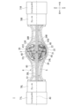
- 2 is a rear view of a cross section of the axle device according to the embodiment taken along a vertical plane passing through the center of the axle along the left-right direction of the vehicle body, showing the oil level when the vehicle is stopped.
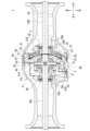
- FIG. 1 is a top view of a cross section of an axle device according to an embodiment taken along a horizontal plane passing through the center of the axle along the left-right direction of the vehicle body, showing the rotation direction of a transmission shaft and the rotation direction of gears.
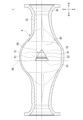
- FIG. 1 is a rear view of a cross section of an axle device according to an embodiment taken along a vertical plane passing through the center of the axle along the left-right direction of the vehicle body, showing a protrusion on an inner wall of a housing.
- FIG. 4 is an enlarged view of a portion of FIG. 3 showing a protrusion on an inner wall of a housing according to the embodiment;
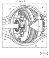
- FIG. 4 is a perspective view showing a protrusion on an inner wall of a housing according to the embodiment.
- FIG. 13 is a rear view of a cross section of an axle device according to a comparative example taken along a vertical plane passing through the center of the axle along the left-right direction of the vehicle body, showing the oil level during rotation.
- axle device mounted on a wheel loader (an example of a vehicle) will be described as an example of the axle device.
- FIG. 1 is a perspective view of a vehicle 100 equipped with an axle device 1 according to an embodiment.
- a vehicle 100 includes a vehicle body 101 , a work machine 102 , a front traveling device 103 , a rear traveling device 104 , and a driver's cab 105 .
- the forward direction (front of the vehicle body), backward direction (rear of the vehicle body) and vehicle width direction (left and right direction of the vehicle body) of the vehicle will be referred to as "front of the vehicle (one side in the front-rear direction of the vehicle)", “rear of the vehicle (the other side in the front-rear direction of the vehicle)” and “vehicle width direction”.
- the vehicle width direction may also be referred to as "left side (one side in the vehicle width direction)" or "right side (the other side in the vehicle width direction)”.
- the right side in the forward direction of the vehicle will be referred to as the right side
- the left side in the forward direction of the vehicle will be referred to as the left side.
- the vehicle up-down direction (up-down direction of the vehicle body), above the vehicle (upper side of the vehicle body) and below the vehicle (lower side of the vehicle body) of the vehicle will be referred to simply as the "up-down direction", "up” and "down”.
- the vehicle is placed on a horizontal plane (horizontal ground).
- the vehicle up-down direction (up-down direction of the vehicle body), above the vehicle (upper side of the vehicle body) and below the vehicle (lower side of the vehicle body) of the vehicle respectively correspond to the up-down direction (vertical direction), vertical up and vertical down when the vehicle is placed on a horizontal plane.
- elements on the left side may end with the symbol L
- elements on the right side may end with the symbol R.
- a driver's cab 105 is provided on the upper part of the vehicle body 101.
- the driver's cab 105 is equipped with a seat for the driver of the vehicle 100 to sit in, as well as levers, pedals, and instruments for various operations.
- the work machine 102 is a machine for excavating or transporting work objects such as soil and sand.
- the work machine 102 is provided at the front of the vehicle body 101.
- the work machine 102 includes a boom, a bucket, a bell crank, a lift cylinder, a bucket cylinder, etc.
- the front traveling device 103 is provided on the front lower part of the vehicle body 101.
- the front traveling device 103 includes a front wheel that is rotatable around the axis of the front axle 112.
- the rear traveling device 104 is provided on the lower rear side of the vehicle body 101.
- the rear traveling device 104 is configured to include rear wheels that are rotatable around the axis of the rear axle 113.
- the vehicle 100 further includes a drive source 110 , a transmission 111 , a front axle 112 , and a rear axle 113 .
- the driving source 110 is mounted on the rear of the vehicle body 101.
- the driving source 110 is a diesel engine (one example of an engine).
- the engine is provided with a fuel injection device that injects fuel into the cylinder of the engine, an engine tachometer that measures the engine speed, and the like.
- the front axle 112 transmits the driving force output by the transmission 111 to the front traveling device 103.
- the front wheels constituting the front traveling device 103 rotate in the direction of arrow R1 (the forward rotation direction in the illustrated example).
- the rear axle 113 transmits the driving force output by the transmission 111 to the rear traveling device 104.
- the rear wheels constituting the rear traveling device 104 rotate in the direction of arrow R2 (the forward rotation direction in the illustrated example).
- Fig. 2 is a rear view of a cross section of the axle device 1 according to the embodiment cut by a vertical plane passing through the axle center AC along the left-right direction of the vehicle body, showing the oil level when the vehicle is stopped.
- Fig. 3 is a top view of a cross section of the axle device 1 according to the embodiment cut by a horizontal plane passing through the axle center AC along the left-right direction of the vehicle body, showing the rotation direction of the transmission shaft 2 and the rotation direction of the gear.
- Fig. 4 is a rear view of a cross section of the axle device 1 according to the embodiment cut by a vertical plane passing through the axle center AC along the left-right direction of the vehicle body, showing the protrusion 80 of the inner wall 61 of the housing 4.
- the differential case 24 comprises a cylindrical right half 24R that opens in the left-right direction of the vehicle body and supports a portion of the right axle shaft 30R, and a cylindrical left half 24L that opens in the left-right direction of the vehicle body and supports a portion of the left axle shaft 30L.
- the differential case 24 is connected to the rear portion 22 of the bevel gear 20 and supports portions of the axle shafts 30L, 30R.
- the outer periphery of the right half 24R is connected to the rear portion 22 of the bevel gear 20.
- the left and right halves 24L, 24R are fixed to each other with fastening members 26 such as bolts.
- the axle shafts 30L, 30R extend along the left-right direction of the vehicle body.
- a pair of axle shafts 30L, 30R are provided on the left and right.
- the left and right axle shafts 30L, 30R are arranged coaxially with each other.
- a pair of side gears 31L, 31R are provided on the left and right sides.
- the side gears 31L, 31R are connected to the inner ends of the axle shafts 30L, 30R in the vehicle width direction.
- the right axle shaft 30R is supported by the right half body 24R via the right side gear 31R.
- the left axle shaft 30L is supported by the left half body 24L via the left side gear 31L.
- the differential pinion shaft 40 extends in four directions perpendicular to each other in the radial direction centered on the axle center AC.
- the differential pinion shaft 40 is positioned offset to the right with respect to the vehicle body left-right center line BC.
- the differential pinion shaft 40 extends forward-rear, rearward, upward, and downward with the axle center AC as its center.
- the portions of the differential pinion shaft 40 that extend forward and rearward, and the portions that extend upward and downward, are each positioned coaxially.
- Differential pinion gears 41A, 41B, 41C, and 41D are supported on differential pinion shaft 40 so as to be rotatable around differential pinion shaft 40. Differential pinion gears 41A, 41B, 41C, and 41D are supported on portions of differential pinion shaft 40 that extend forward, backward, upward, and downward, respectively. Differential pinion gears 41A, 41B, 41C, and 41D mesh with side gears 31L and 31R.
- the bearings 50L, 50R are provided in a pair on the left and right.
- the bearings 50L, 50R are arranged between the differential case 24 and the housing 4.
- the bearings 50L, 50R rotatably support the differential case 24 to which the bevel gear 20 is connected.
- the right bearing 50R is arranged between the outer periphery of the right half body 24R and the right inner periphery of the housing 4.
- the left bearing 50L is arranged between the outer periphery of the left half body 24L and the left inner periphery of the housing 4.
- the bevel gear 20 rotates in the direction of the arrow J2 (the forward rotation direction in the illustrated example). Then, as the bevel gear 20 rotates, the side gears 31L, 31R and the axle shafts 30L, 30R rotate together. For example, when the vehicle 100 is traveling straight ahead and there is no speed difference (difference in rotation speed) between the left and right wheels, the left and right side gears 31L, 31R and the axle shafts 30L, 30R rotate at the same speed.
- the housing 4 is a front housing located at the front side in the longitudinal direction of the vehicle body.
- the housing 4 is formed in a cylindrical shape along the transverse direction of the vehicle body.
- An internal space 60 is formed in the housing 4 to accommodate the differential device 3.
- a portion of the housing 4 that accommodates the bevel gear 20 bulges outward in the radial direction more than a portion that accommodates the axle shafts 30L, 30R.
- an inner wall 61 of the portion of the housing 4 that accommodates the bevel gear 20 is curved toward the front side.
- lubricating oil 5 is stored in the internal space 60 of the housing 4.
- the initial liquid level S1 of the lubricating oil 5 before the bevel gear 20 rotates (hereinafter also referred to as the "initial oil level S1") is located along the central axis of the axle shafts 30L, 30R.
- the initial oil level S1 is located between the upper edges of the axle shafts 30L, 30R and the axle center AC. Note that the initial oil level S1 is not limited to the above and can be changed according to the design specifications.
- the axle device 1 further includes shrouds 65, 66 that guide the lubricating oil 5 that flows around the bevel gear 20 due to the rotation of the bevel gear 20.
- the shrouds 65, 66 are disposed with a gap between them and the inner wall 61 of the housing 4.
- the shrouds 65, 66 are configured to include a plate-shaped portion that is aligned with the rotation direction of the bevel gear 20.
- a pair of shrouds 65, 66 are provided via the bevel gear 20.
- the pair of shrouds 65, 66 includes a tooth surface side shroud 65 arranged with a gap between it and the tooth surface portion 21 of the bevel gear 20, and a back surface side shroud 66 arranged with a gap between it and the case back surface portion 27 of the differential case 24.
- the configuration of the shrouds 65, 66 is not limited to the above, and can be changed according to the design specifications.
- the axle device 1 further includes wet multi-plate brakes 70L, 70R at the outer ends in the left-right direction of the vehicle body.
- a pair of brakes 70L, 70R are provided on the left and right sides.
- the brakes 70L, 70R are disposed between the outer ends in the vehicle width direction of the axle shafts 30L, 30R and the final gears 71L, 71R.
- the rotation of the engine which is shifted by the transmission 111, is finally decelerated by the final gears 71L, 71R and transmitted to the tires.
- part of the outer shape of the protrusion 80 overlaps with the center BC in the left-right direction of the vehicle body.
- part of the outer shape of the protrusion 80 overlaps with the outer end of the bevel gear 20 in the left-right direction of the vehicle body.
- part of the outer shape of the protrusion 80 overlaps with the liquid level S2 of the lubricating oil 5 (hereinafter also referred to as "oil level S2 when tilted forward").
- the oil level S2 when tilted forward is located higher on the vehicle body than the initial oil level S1.
- a portion of the protrusion 80 overlaps with the transmission shaft 2. At least a portion of the protrusion 80 is immersed in the lubricating oil 5. For example, at the initial oil level S1, approximately half of the protrusion 80 may be immersed in the lubricating oil 5. Note that the manner in which the protrusion 80 is immersed in the lubricating oil 5 is not limited to the above and can be changed according to the design specifications.
- the size of the gap G between the protrusion 80 and the bevel gear 20 is 5 mm or more and 10 mm or less.
- the gap G between the protrusion 80 and the bevel gear 20 corresponds to the minimum distance between the protrusion 80 and the bevel gear 20.
- a recess 81 is formed in the portion of the protrusion 80 that faces the side portion 23 of the bevel gear 20.
- the bottom surface of the recess 81 is disposed with a uniform gap G along the side portion 23 of the bevel gear 20 in the rotational direction and axial direction of the bevel gear 20.
- the contour of the protrusion 80 may be set by the following steps (1) to (6).
- the right end of the protrusion 80 is set in a position overlapping with the bolt head 25 located on the right side of the case rear portion 27 when viewed from the front-rear direction of the vehicle body.
- the left end of the protrusion 80 is set at a position overlapping with the center BC in the left-right direction of the vehicle body when viewed from the front-rear direction of the vehicle body.
- the angle between the side V3 (side running in the vertical direction of the vehicle body) along the left end of the protrusion 80 in (2) above and the side V1 in (3) above is set to 60 degrees.
- side V2 of the outer shape of the protrusion 80 inclines from the lower side in the vertical direction of the vehicle body toward the axle center AC as it moves from the tooth surface side to the back surface side of the bevel gear 20.
- the side V2 is set at a position that is linearly symmetrical with respect to side V1 in (4) above, with the axle center AC as the axis of symmetry.
- the portion of the projection 80 that faces the side surface 23 of the bevel gear 20 is spaced from the side surface 23 of the bevel gear 20 by a gap G of about 10 mm.
- the procedure for setting the outer shape of the protrusion 80 is not limited to the above, and can be changed according to the design specifications.
- the axle device 1 of this embodiment is provided on the vehicle body 101.
- the axle device 1 includes the transmission shaft 2 that transmits rotational power from the drive source 110, the differential device 3 including the bevel gear 20 that rotates about an axis along the left-right direction of the vehicle body by rotation of the transmission shaft 2, and the housing 4 that accommodates the differential device 3 and stores the lubricating oil 5 for lubricating the differential device 3.
- the housing 4 includes a protrusion 80 on an inner wall 61 that faces the outer periphery of the bevel gear 20.
- the rotation of the bevel gear 20X may cause a difference in the level of the lubricating oil 5 between the left and right sides.
- the oil level is higher on the tooth surface side of the bevel gear 20X than on the opposite side (back side) of the tooth surface of the bevel gear 20X.
- a difference occurs in the cooling capacity of the left and right brakes.
- the oil level may be adjusted to the lower side and the initial oil level may be determined.
- the oil is wasted due to the difference in the oil level between the left and right sides, which may result in increased oil costs and oil agitation loss.
- the gap G between the inner wall 61 of the housing 4 and the outer periphery of the bevel gear 20 can be narrowed by the protrusions 80. Therefore, the flow rate of the oil flowing around the bevel gear 20 due to the rotation of the bevel gear 20 can be increased by the squeezing effect of the protrusions 80.
- This makes it possible to increase the flow rate of the oil flowing toward the back side of the bevel gear 20 rather than the tooth surface side (for example, the oil flowing in the direction of the arrow in FIG. 6). Therefore, the flow rate of the oil flowing from the side with a high oil level to the side with a low oil level can be increased by the rotation of the bevel gear 20. Therefore, the difference in the oil level between the left and right sides can be reduced.
- a portion of the outer shape of the protrusion 80 overlaps with the center BC in the vehicle body transverse direction. For example, if the contour of the protrusion 80 extends too far in the direction of the tooth surface side of the bevel gear 20 relative to the center BC in the left-right direction of the vehicle when viewed from the front-rear direction of the vehicle, it will obstruct the flow of oil from the tooth surface side to the back side of the bevel gear 20.
- a portion of the projection 80 overlaps with the transmission shaft 2 when viewed from the front-rear direction of the vehicle body. According to this configuration, the flow rate of oil flowing around the bevel gear 20 due to the rotation of the bevel gear 20 accompanying the rotation of the transmission shaft 2 can be more effectively increased by the throttling effect of the protrusions 80 .
- the housing 4 is a front housing that is disposed at the front side in the vehicle front-rear direction.
- the protrusion 80 is provided on a front inner wall 61 of the front housing. According to this configuration, the difference in oil level between the left and right sides in the internal space 60 of the front housing can be reduced.
- the protrusion 80 is immersed in the lubricating oil 5 . According to this configuration, the flow rate of oil flowing around the bevel gear 20 due to the rotation of the bevel gear 20 can be more effectively increased by the throttling effect of the protrusions 80 .
- the size of the gap G between the projection 80 and the bevel gear 20 is equal to or greater than 5 mm and equal to or less than 10 mm.
- the size of the gap G between the protrusion 80 and the bevel gear 20 is less than 5 mm, the gap G will be too small, and there is a high possibility that the necessary dimensions cannot be secured taking into consideration the rotational variations of the bevel gear 20, the manufacturing variations of the housing 4, and the adjustment allowance during assembly of the differential device 3.
- the size of the gap G between the protrusion 80 and the bevel gear 20 exceeds 10 mm, there is a high possibility that the squeezing effect of the protrusion 80 cannot be sufficiently obtained.
- a part of the outer shape of the projection 80 when viewed from the front-rear direction of the vehicle body, a part of the outer shape of the projection 80 is inclined so as to approach the axle center AC from the tooth surface side to the back surface side of the bevel gear 20 .
- the oil that flows around the bevel gear 20 due to the rotation of the bevel gear 20 can be more easily guided from the tooth surface side to the back surface side of the bevel gear 20. Therefore, the difference in oil level between the left and right sides can be more effectively reduced.
- the outer shape of the protrusion 80 overlaps with the outer shape of a triangle that includes two sides V1, V2 that incline from the upper and lower sides in the vertical direction of the vehicle body toward the axle center AC as they move from the tooth surface side toward the back surface side of the bevel gear 20, and one side V3 that runs along the left-right center line BC of the vehicle body.
- the oil flowing around the bevel gear 20 due to each of the forward and reverse rotations of the bevel gear 20 can be easily guided from the tooth surface side to the back surface side of the bevel gear 20. Therefore, the difference in oil level between the left and right sides can be more effectively reduced. For example, the difference in oil level between the left and right sides can be more effectively reduced when the vehicle 100 is traveling forward and backward.
- the axle device 1 further includes a shroud 65 that guides the lubricating oil 5 that flows around the bevel gear 20 due to the rotation of the bevel gear 20.
- a part of the outer shape of the projection 80 overlaps with the shroud 65 when viewed from the front-rear direction of the vehicle body. According to this configuration, the flow rate of the oil that flows around the bevel gear 20 as the bevel gear 20 rotates and is guided by the shroud 65 can be more effectively increased by the throttling effect of the protrusions 80 .
- the axle device 1 further includes wet multi-plate brakes 70L, 70R at the outer ends in the left-right direction of the vehicle body. At least a portion of the brakes 70L, 70R is immersed in the lubricating oil 5. According to this configuration, the brakes 70L, 70R can be cooled by the lubricating oil 5, so that the braking performance of the brakes 70L, 70R can be maintained.
- ⁇ Modification> In the above embodiment, an example has been described in which a part of the outer shape of the protrusion overlaps with the center in the left-right direction of the vehicle body when viewed from the front-rear direction of the vehicle body, but this is not limited thereto.
- the entire outer shape of the protrusion does not have to overlap with the center in the left-right direction of the vehicle body when viewed from the front-rear direction of the vehicle body.
- the outer shape of the protrusion may extend long in the direction of the tooth surface side of the bevel gear with respect to the center in the left-right direction of the vehicle body when viewed from the front-rear direction of the vehicle body.
- the arrangement of the outer shape of the protrusion with respect to the center in the left-right direction of the vehicle body can be changed according to the design specifications.
- a part of the outer shape of the protrusion overlaps with the outer end of the bevel gear in the left-right direction of the vehicle body when viewed from the front-rear direction of the vehicle body, but this is not limited to this.
- the entire outer shape of the protrusion does not have to overlap with the outer end of the bevel gear in the left-right direction of the vehicle body when viewed from the front-rear direction of the vehicle body.
- the arrangement of the outer shape of the protrusion relative to the outer end of the bevel gear in the left-right direction of the vehicle body can be changed according to the design specifications.
- the housing is a front housing arranged at the front side in the fore-and-aft direction of the vehicle body, and the protrusion is provided on the front inner wall of the front housing, but this is not limited to the above.
- the housing may be a rear housing arranged at the rear side in the fore-and-aft direction of the vehicle body, and the protrusion may be provided on the rear inner wall of the rear housing.
- the protrusion may be provided on the front inner wall of the front housing and/or the rear inner wall of the rear housing.
- the manner in which the protrusion is provided on the front housing and the rear housing can be changed according to the design specifications.
- the size of the gap between the protrusion and the bevel gear is described as being 5 mm or more and 10 mm or less, but this is not limited to this.
- the size of the gap between the protrusion and the bevel gear may be less than 5 mm or more than 10 mm.
- the size of the gap between the protrusion and the bevel gear can be changed according to the design specifications.
- a portion of the outer shape of the protrusion when viewed from the front-rear direction of the vehicle body, is inclined so as to approach the center of the axle as it moves from the tooth surface side to the back surface side of the bevel gear, but this is not limited to this.
- the outer shape of the protrusion may extend uniformly in the left-right direction of the vehicle body from the tooth surface side to the back surface side of the bevel gear.
- the inclination manner of the outer shape of the protrusion with respect to the center of the axle can be changed according to the design specifications.
- the outer shape of the protrusion may be a polygon such as a rectangle or a pentagon, a curved outer shape such as a circle, an ellipse, or an oval, an outer shape that includes straight lines and curves, or an outer shape that is a combination of these.
- the form of the outer shape of the protrusion can be changed according to the design specifications.
- the axle device further includes a shroud that guides the lubricating oil that flows around the bevel gear as the bevel gear rotates, and an example has been described in which a portion of the outer shape of the protrusion overlaps with the shroud when viewed from the front-to-rear direction of the vehicle body, but this is not limited to this.
- the entire outer shape of the protrusion does not have to overlap with the shroud when viewed from the front-to-rear direction of the vehicle body.
- the axle device does not need to include a shroud.
- the arrangement of the outer shape of the protrusion relative to the shroud and/or the installation of the shroud can be changed according to design specifications.
- the axle device further includes a wet multi-plate brake on the outer end side in the left-right direction of the vehicle body, and at least a portion of the brake is immersed in lubricating oil, but this is not limited to the above.
- the entire brake does not have to be immersed in lubricating oil.
- at least a portion of the brake may be immersed in an oil other than the above-mentioned lubricating oil.
- the axle device may not include the above-mentioned brake.
- the axle device may include a brake other than a wet multi-plate brake.
- the manner in which the brake is immersed in lubricating oil and/or the manner in which the brake is installed can be changed according to the design specifications.
- the axle device has been described as transmitting the force from the diesel engine, which is the driving source, through the transmission to the wheels, but this is not limited thereto.
- the driving source may be an engine other than a diesel engine.
- the axle device may transmit rotational power from a power source other than an engine to the wheels.
- the type of the driving source may be changed according to the design specifications.
- the axle device is described as being mounted on a wheel loader, but this is not limiting.
- the axle device may be mounted on other work vehicles such as a shovel, bulldozer, dump truck, etc.
- the type of vehicle on which the axle device is mounted can be changed according to the design specifications.
- the gear that rotates about an axis along the left-right direction of the vehicle body due to rotation of the transmission shaft is a bevel gear, but this is not limited to this.
- the gear that rotates about an axis along the left-right direction of the vehicle body due to rotation of the transmission shaft may be configured to include other gears such as spur gears, helical gears, screw gears, double helical gears, and spherical gears.
- the configuration of the gear that rotates about an axis along the left-right direction of the vehicle body due to rotation of the transmission shaft can be changed according to the design specifications.
- An axle device provided on a vehicle body, A transmission shaft that transmits rotational power from a drive source; a differential device including a gear that rotates about an axis along the left-right direction of the vehicle body by rotation of the transmission shaft; a housing that accommodates the differential device and stores lubricating oil for lubricating the differential device, The housing has a protrusion on an inner wall facing an outer periphery of the gear. Axle device.
- the housing is a front housing disposed at a front side in a vehicle body longitudinal direction, or a rear housing disposed at a rear side in the vehicle body longitudinal direction, The protrusion is provided on a front inner wall of the front housing or a rear inner wall of the rear housing. 6.
- An axle device according to any one of claims 1 to 5.
- a wet multi-plate brake is provided at an outer end side in the left-right direction of the vehicle body, At least a portion of the brake is immersed in the lubricating oil. 12.
- An axle device according to any one of claims 1 to 11.
- the difference in oil level between the left and right sides can be reduced.
Landscapes
- Engineering & Computer Science (AREA)
- General Engineering & Computer Science (AREA)
- Mechanical Engineering (AREA)
- General Details Of Gearings (AREA)
Abstract
車軸装置は、車体に設けられた車軸装置であって、駆動源からの回転動力を伝達する伝達軸と、前記伝達軸の回転により車体左右方向に沿う軸を中心に回転するギヤを含む差動装置と、前記差動装置を収容するとともに、前記差動装置を潤滑するための潤滑油を貯留するハウジングと、を備え、前記ハウジングは、前記ギヤの外周と対向する内壁に突起を備える。
Description
本発明は、車軸装置に関する。
本願は、2023年7月5日に日本に出願された特願2023-110861号について優先権を主張し、その内容をここに援用する。
本願は、2023年7月5日に日本に出願された特願2023-110861号について優先権を主張し、その内容をここに援用する。
特許文献1には、キャリアの底部に貯留される潤滑油を一方のベアリングに供給する動力伝達装置の潤滑構造が開示されている。キャリアの内壁面には、回転するピニオンギヤによって掻き揚げられる潤滑油を一方のベアリングに供給する溝状の流路が形成される。流路の上方には、掻き揚げられた潤滑油を一方のベアリングに誘導するための突片が設けられる。
一方、エンジンからトランスミッションを通過した力を車輪に伝えるアクスルを含む車軸装置が知られている。車軸装置は、エンジンからの回転動力を伝達するドライブシャフトと、ドライブシャフトの回転により車体左右方向に沿う軸を中心に回転するベベルギヤを含む差動装置と、差動装置を収容するとともに、差動装置を潤滑するための潤滑油を貯留するハウジングと、を備える。
一方、エンジンからトランスミッションを通過した力を車輪に伝えるアクスルを含む車軸装置が知られている。車軸装置は、エンジンからの回転動力を伝達するドライブシャフトと、ドライブシャフトの回転により車体左右方向に沿う軸を中心に回転するベベルギヤを含む差動装置と、差動装置を収容するとともに、差動装置を潤滑するための潤滑油を貯留するハウジングと、を備える。
車軸装置では、ベベルギヤの回転により、潤滑油の液面の高さ(以下「オイルレベル」ともいう。)に左右差が生じる場合がある。例えば、ベベルギヤの歯面側では、ベベルギヤの歯面とは反対側(背面側)よりもオイルレベルが高くなる。この場合、左右のブレーキの冷却能力に差が生じる。例えば、この差を無くすために、オイルレベルを低い側に合わせ、初期のオイルレベルを決定する場合がある。しかしこの場合、オイルレベルの左右差の分、オイルが無駄となり、オイルコストの増加、オイルの攪拌ロスとなり得る。そのため、オイルレベルの左右差を低減する上で改善の余地がある。
そこで本発明は、オイルレベルの左右差を低減することができる車軸装置を提供することを目的とする。
本発明の一態様に係る車軸装置は、車体に設けられた車軸装置であって、駆動源からの回転動力を伝達する伝達軸と、前記伝達軸の回転により車体左右方向に沿う軸を中心に回転するギヤを含む差動装置と、前記差動装置を収容するとともに、前記差動装置を潤滑するための潤滑油を貯留するハウジングと、を備え、前記ハウジングは、前記ギヤの外周と対向する内壁に突起を備える。
上記態様によれば、オイルレベルの左右差を低減することができる。
以下、本発明の実施形態について図面を参照して説明する。実施形態においては、車軸装置として、ホイールローダ(車両の一例)に搭載された車軸装置を挙げて説明する。
以下の説明において、例えば「平行」や「直交」、「中心」、「同軸」等の相対的又は絶対的な配置を示す表現は、厳密にそのような配置や状態を意味するのみならず、公差や同じ機能が得られる程度の角度や距離をもって相対的に変位している配置や状態をも含むものとする。以下の説明に用いる図面では、各部材を認識可能な大きさとするため、各部材の縮尺を適宜変更して示す場合がある。
<車両>
図1は、実施形態に係る車軸装置1を搭載した車両100の斜視図である。
図1に示すように、車両100は、車体101、作業機102、前側走行装置103、後側走行装置104及び運転室105を備える。
図1は、実施形態に係る車軸装置1を搭載した車両100の斜視図である。
図1に示すように、車両100は、車体101、作業機102、前側走行装置103、後側走行装置104及び運転室105を備える。
以下、車両の前進方向(車体前方)、後進方向(車体後方)及び車両幅方向(車体左右方向)を「車両前方(車両前後方向一方側)」、「車両後方(車両前後方向他方側)」及び「車両幅方向」と称する。車両幅方向は、「左側(車両幅方向一方側)」又は「右側(車両幅方向他方側)」と称する場合もある。車両が前進する方向に対して右手を右側、車両が前進する方向に対して左手を左側と称する。車両の車両上下方向(車体上下方向)、車両上方(車体上方)及び車両下方(車体下方)を単に「上下方向」、「上方」及び「下方」と称する。図の例では、車両は、水平面(水平な地面)に配置されている。車両の車両上下方向(車体上下方向)、車両上方(車体上方)及び車両下方(車体下方)は、車両が水平面に配置された状態の上下方向(鉛直方向)、鉛直上方及び鉛直下方とそれぞれ一致する。以下の説明では、左側の要素の末尾に符号Lを付し、右側の要素の末尾に符号Rを付す場合がある。
車体101の上部には、運転室105が設けられる。例えば、運転室105には、車両100の運転者が座るためのシートや、各種操作のためのレバー、ペダル及び計器類が内装されている。
作業機102は、土砂等の作業対象物の掘削又は運搬を行うための機械である。作業機102は、車体101の前部に設けられる。例えば、作業機102は、ブーム、バケット、ベルクランク、リフトシリンダ及びバケットシリンダ等を含んで構成される。
前側走行装置103は、車体101の前側下部に設けられる。前側走行装置103は、フロントアクスル112の軸回りに回転可能な前輪を含んで構成される。
後側走行装置104は、車体101の後側下部に設けられる。後側走行装置104は、リヤアクスル113の軸回りに回転可能な後輪を含んで構成される。
後側走行装置104は、車体101の後側下部に設けられる。後側走行装置104は、リヤアクスル113の軸回りに回転可能な後輪を含んで構成される。
車両100は、駆動源110、トランスミッション111、フロントアクスル112及びリヤアクスル113を更に備える。
駆動源110は、車体101の後部に搭載される。例えば、駆動源110は、ディーゼルエンジン(エンジンの一例)である。例えば、エンジンには、エンジンのシリンダ内に燃料を噴射する燃料噴射装置や、エンジンの回転数を計測するエンジン回転計等が設けられる。
駆動源110は、車体101の後部に搭載される。例えば、駆動源110は、ディーゼルエンジン(エンジンの一例)である。例えば、エンジンには、エンジンのシリンダ内に燃料を噴射する燃料噴射装置や、エンジンの回転数を計測するエンジン回転計等が設けられる。
トランスミッション111は、入力軸に入力される駆動力を変速して出力軸から出力する。トランスミッション111の入力軸は、エンジンに接続される。トランスミッション111の出力軸は、フロントアクスル112及びリヤアクスル113に接続される。トランスミッション111は、エンジンの駆動力をフロントアクスル112及びリヤアクスル113に伝達する。
フロントアクスル112は、トランスミッション111が出力する駆動力を前側走行装置103に伝達する。これにより、前側走行装置103を構成する前輪が矢印R1方向(図の例では前進時回転方向)に回転する。
リヤアクスル113は、トランスミッション111が出力する駆動力を後側走行装置104に伝達する。これにより、後側走行装置104を構成する後輪が矢印R2方向(図の例では前進時回転方向)に回転する。
リヤアクスル113は、トランスミッション111が出力する駆動力を後側走行装置104に伝達する。これにより、後側走行装置104を構成する後輪が矢印R2方向(図の例では前進時回転方向)に回転する。
<車軸装置>
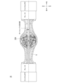
図2は、実施形態に係る車軸装置1を車体左右方向に沿う車軸中心ACを通る鉛直面で切断した断面の後面視であって、車両が停止している状態のオイルレベルを示す図である。図3は、実施形態に係る車軸装置1を車体左右方向に沿う車軸中心ACを通る水平面で切断した断面の上面視であって、伝達軸2の回転方向とギヤの回転方向とを示す図である。図4は、実施形態に係る車軸装置1を車体左右方向に沿う車軸中心ACを通る鉛直面で切断した断面の後面視であって、ハウジング4の内壁61の突起80を示す図である。図3及び図4においては、潤滑油5の図示を省略している。
図2から図4を併せて参照し、車体101には、車軸装置1が設けられる。車軸装置1は、駆動源110からの回転動力を伝達する伝達軸2と、伝達軸2の回転により車体左右方向に沿う軸を中心に回転するギヤを含む差動装置3と、差動装置3を収容するとともに、差動装置3を潤滑するための潤滑油5を貯留するハウジング4と、を備える。
フロントアクスル112及びリヤアクスル113は、車軸装置1の一実施形態である。
図2は、実施形態に係る車軸装置1を車体左右方向に沿う車軸中心ACを通る鉛直面で切断した断面の後面視であって、車両が停止している状態のオイルレベルを示す図である。図3は、実施形態に係る車軸装置1を車体左右方向に沿う車軸中心ACを通る水平面で切断した断面の上面視であって、伝達軸2の回転方向とギヤの回転方向とを示す図である。図4は、実施形態に係る車軸装置1を車体左右方向に沿う車軸中心ACを通る鉛直面で切断した断面の後面視であって、ハウジング4の内壁61の突起80を示す図である。図3及び図4においては、潤滑油5の図示を省略している。
図2から図4を併せて参照し、車体101には、車軸装置1が設けられる。車軸装置1は、駆動源110からの回転動力を伝達する伝達軸2と、伝達軸2の回転により車体左右方向に沿う軸を中心に回転するギヤを含む差動装置3と、差動装置3を収容するとともに、差動装置3を潤滑するための潤滑油5を貯留するハウジング4と、を備える。
フロントアクスル112及びリヤアクスル113は、車軸装置1の一実施形態である。
<伝達軸>
伝達軸2は、車体前後方向に沿うように延びる。伝達軸2は、車体左右方向の中心BC(以下「車体左右中心線BC」ともいう。)に配置される。伝達軸2は、トランスミッション111の出力軸に接続される。伝達軸2の前端部には、ベベルギヤ20(傘歯車、伝達軸2の回転により車体左右方向に沿う軸を中心に回転するギヤの一例)に噛み合う歯10(以下「ドライブピニオンギヤ10」ともいう。)が設けられる。
伝達軸2は、車体前後方向に沿うように延びる。伝達軸2は、車体左右方向の中心BC(以下「車体左右中心線BC」ともいう。)に配置される。伝達軸2は、トランスミッション111の出力軸に接続される。伝達軸2の前端部には、ベベルギヤ20(傘歯車、伝達軸2の回転により車体左右方向に沿う軸を中心に回転するギヤの一例)に噛み合う歯10(以下「ドライブピニオンギヤ10」ともいう。)が設けられる。
<差動装置>
差動装置3は、ベベルギヤ20、アクスルシャフト30L,30R、サイドギヤ31L,31R、デフピニオンシャフト40、デフピニオンギヤ41A,41B,41C,41D及び軸受50L,50Rを備える。ベベルギヤ20は、車体左右方向の中心BCに対して車体左右方向の一方にオフセットして配置される。図の例では、ベベルギヤ20は、車体左右方向の中心BCに対して右側にオフセットして配置される。なお、ベベルギヤ20の配置態様は、上記に限らず、設計仕様に応じて変更することができる。
差動装置3は、ベベルギヤ20、アクスルシャフト30L,30R、サイドギヤ31L,31R、デフピニオンシャフト40、デフピニオンギヤ41A,41B,41C,41D及び軸受50L,50Rを備える。ベベルギヤ20は、車体左右方向の中心BCに対して車体左右方向の一方にオフセットして配置される。図の例では、ベベルギヤ20は、車体左右方向の中心BCに対して右側にオフセットして配置される。なお、ベベルギヤ20の配置態様は、上記に限らず、設計仕様に応じて変更することができる。
ベベルギヤ20は、ドライブピニオンギヤ10に噛み合う歯を有する歯面部21と、車体左右方向において歯面部21とは反対側に配置される背面部22と、ベベルギヤ20の径方向外側に位置し歯面部21と背面部22とを繋ぐ側面部23と、を備える。例えば、歯面部21において歯が設けられた側(歯面側)と反対側の部分(背面側の部分)は、ボルト等の締結部材で後述するディファレンシャルケース24に固定される。図の例では、ボルトの頭部25は、ディファレンシャルケース24のケース背面部27の右側に配置される。
ディファレンシャルケース24は、車体左右方向に開口し右側のアクスルシャフト30Rの一部を支持する筒状の右側半体24Rと、車体左右方向に開口し左側のアクスルシャフト30Lの一部を支持する筒状の左側半体24Lと、を備える。ディファレンシャルケース24は、ベベルギヤ20の背面部22に繋がりアクスルシャフト30L,30Rの一部を支持する。右側半体24Rの外周部は、ベベルギヤ20の背面部22に繋がっている。例えば、左右の半体24L,24Rは、ボルト等の締結部材26で互いに固定される。
アクスルシャフト30L,30Rは、車体左右方向に沿うように延びる。アクスルシャフト30L,30Rは、左右一対設けられる。左右のアクスルシャフト30L,30Rは、互いに同軸上に配置される。
サイドギヤ31L,31Rは、左右一対設けられる。サイドギヤ31L,31Rは、アクスルシャフト30L,30Rの車幅方向内端部に連結される。右側のアクスルシャフト30Rは、右側のサイドギヤ31Rを介して右側半体24Rに支持される。左側のアクスルシャフト30Lは、左側のサイドギヤ31Lを介して左側半体24Lに支持される。
デフピニオンシャフト40は、車軸中心ACを中心とする半径方向に対して互いに直交する四方向に延びる。デフピニオンシャフト40は、車体左右中心線BCに対して右側にオフセットして配置される。デフピニオンシャフト40は、車軸中心ACを中心として、前方後、後方向、上方向及び下方向に延びる。デフピニオンシャフト40において、前方向及び後方向に延びる部分、並びに、上方向及び下方向に延びる部分は、それぞれ同軸上に配置される。
デフピニオンギヤ41A,41B,41C,41Dは、デフピニオンシャフト40を中心として回転可能にデフピニオンシャフト40に支持される。デフピニオンギヤ41A,41B,41C,41Dは、デフピニオンシャフト40において前方向、後方向、上方向及び下方向に延びる部分にそれぞれ支持される。デフピニオンギヤ41A,41B,41C,41Dは、サイドギヤ31L,31Rに噛み合っている。
軸受50L,50Rは、左右一対設けられる。軸受50L,50Rは、ディファレンシャルケース24とハウジング4との間に配置される。軸受50L,50Rは、ベベルギヤ20が連結されたディファレンシャルケース24を回転可能に支持する。右側の軸受50Rは、右側半体24Rの外周部とハウジング4の右側内周部との間に配置される。左側の軸受50Lは、左側半体24Lの外周部とハウジング4の左側内周部との間に配置される。
例えば、伝達軸2が矢印J1方向(図の例では前進時回転方向)に回転すると、ベベルギヤ20が矢印J2方向(図の例では前進時回転方向)に回転する。すると、ベベルギヤ20の回転に伴ってサイドギヤ31L,31R及びアクスルシャフト30L,30Rが一体に回転する。例えば、車両100の直進走行時に、左右の車輪に速度差(回転数の差)が生じない場合、左右のサイドギヤ31L,31R及びアクスルシャフト30L,30Rは同じ速度で回転する。
一方、左右のサイドギヤ31L,31Rの一方に負荷がかかると(例えば、一方が固定されると)、デフピニオンギヤ41A,41B,41C,41Dは回転しながら他方のサイドギヤ31L,31Rを余分に回転させる。例えば、車両100がカーブを曲がる時に、左右の車輪に速度差(回転数の差)が生じる場合、この速度差を吸収することができる。
<ハウジング>
ハウジング4は、車体前後方向の前側に配置されたフロントハウジングである。ハウジング4は、車体左右方向に沿う筒状に形成される。ハウジング4には、差動装置3を収容する内部空間60が形成される。ハウジング4においてベベルギヤ20を収容する部分は、アクスルシャフト30L,30Rを収容する部分よりも径方向外側に膨出している。図の断面視で、ハウジング4においてベベルギヤ20を収容する部分の内壁61は、前側に向かって湾曲している。
ハウジング4は、車体前後方向の前側に配置されたフロントハウジングである。ハウジング4は、車体左右方向に沿う筒状に形成される。ハウジング4には、差動装置3を収容する内部空間60が形成される。ハウジング4においてベベルギヤ20を収容する部分は、アクスルシャフト30L,30Rを収容する部分よりも径方向外側に膨出している。図の断面視で、ハウジング4においてベベルギヤ20を収容する部分の内壁61は、前側に向かって湾曲している。
図2に示すように、ハウジング4の内部空間60には、潤滑油5が貯留される。図の例では、ベベルギヤ20が回転する前の初期の潤滑油5の液面の高さS1(以下「初期のオイルレベルS1」ともいう。)は、アクスルシャフト30L,30Rの中心軸に沿う位置にある。図の例では、初期のオイルレベルS1は、アクスルシャフト30L,30Rの上縁と車軸中心ACとの間に配置される。なお、初期のオイルレベルS1は、上記に限らず、設計仕様に応じて変更することができる。
<シュラウド>
図2及び図3を併せて参照し、車軸装置1は、ベベルギヤ20の回転によりベベルギヤ20の周囲を流れる潤滑油5を案内するシュラウド65,66を更に備える。シュラウド65,66は、ハウジング4の内壁61と隙間を介して配置される。シュラウド65,66は、ベベルギヤ20の回転方向に沿う板状の部分を含んで構成される。
図2及び図3を併せて参照し、車軸装置1は、ベベルギヤ20の回転によりベベルギヤ20の周囲を流れる潤滑油5を案内するシュラウド65,66を更に備える。シュラウド65,66は、ハウジング4の内壁61と隙間を介して配置される。シュラウド65,66は、ベベルギヤ20の回転方向に沿う板状の部分を含んで構成される。
図の例では、シュラウド65,66は、ベベルギヤ20を介して一対設けられる。一対のシュラウド65,66は、ベベルギヤ20の歯面部21と隙間を介して配置される歯面側シュラウド65と、ディファレンシャルケース24のケース背面部27と隙間を介して配置される背面側シュラウド66と、を含んで構成される。なお、シュラウド65,66の構成態様は、上記に限らず、設計仕様に応じて変更することができる。
<ブレーキ>
車軸装置1は、車体左右方向の外端側に、湿式多板式のブレーキ70L,70Rを更に備える。ブレーキ70L,70Rは、左右一対設けられる。ブレーキ70L,70Rは、アクスルシャフト30L,30Rの車幅方向外端部とファイナルギヤ71L,71Rとの間に配置される。例えば、トランスミッション111で変速されたエンジンの回転は、ファイナルギヤ71L,71Rで最終的に減速されてタイヤに伝わる。
車軸装置1は、車体左右方向の外端側に、湿式多板式のブレーキ70L,70Rを更に備える。ブレーキ70L,70Rは、左右一対設けられる。ブレーキ70L,70Rは、アクスルシャフト30L,30Rの車幅方向外端部とファイナルギヤ71L,71Rとの間に配置される。例えば、トランスミッション111で変速されたエンジンの回転は、ファイナルギヤ71L,71Rで最終的に減速されてタイヤに伝わる。
ブレーキ70L,70Rの少なくとも一部は、潤滑油5に浸る。例えば、初期のオイルレベルS1では、ブレーキ70L,70Rの約半分が潤滑油5に浸ってもよい。なお、ブレーキ70L,70Rが潤滑油5に浸る態様は、上記に限らず、設計仕様に応じて変更することができる。
<突起>
図5は、実施形態に係るハウジング4の内壁61の突起80を示す図であって、図3の一部を拡大して示す図である。図6は、実施形態に係るハウジング4の内壁61の突起80を示す斜視図である。図6においては、突起80が設けられるハウジング4の内壁61(前側内壁61)の図示を省略している。
図5及び図6を併せて参照し、ハウジング4は、ベベルギヤ20の外周と対向する内壁61に突起80を備える。突起80は、フロントハウジングの前側内壁61に設けられる。
図5は、実施形態に係るハウジング4の内壁61の突起80を示す図であって、図3の一部を拡大して示す図である。図6は、実施形態に係るハウジング4の内壁61の突起80を示す斜視図である。図6においては、突起80が設けられるハウジング4の内壁61(前側内壁61)の図示を省略している。
図5及び図6を併せて参照し、ハウジング4は、ベベルギヤ20の外周と対向する内壁61に突起80を備える。突起80は、フロントハウジングの前側内壁61に設けられる。
突起80は、ハウジング4の前側内壁61からベベルギヤ20の外周に向かって突出している。例えば、突起80は、ハウジング4の前側内壁61と同一の部材で一体に形成されてもよい。例えばこの場合、突起80は、ハウジング4の一部から隆起する隆起部でもよい。なお、突起80は、隆起部であることに限らず、ハウジング4の前側内壁61とは異なる部材(板状部材)で形成されてもよい。例えばこの場合、突起80を形成する板状部材は、ハウジング4の前側内壁61に溶接等で固定されてもよい。例えば、突起80の態様は、上記に限らず、設計仕様に応じて変更することができる。
図4及び図5を併せて参照し、車体前後方向から見て、突起80の外形の一部は、車体左右方向の中心BCと重なる。図の例では、車体前後方向から見て、突起80の外形の一部は、ベベルギヤ20の車体左右方向の外端と重なる。図の例では、車体前後方向に対して前下がりに車体101を6度前傾させた場合に、突起80の外形の一部は、潤滑油5の液面S2(以下「前傾時のオイルレベルS2」ともいう。)と重なる。前傾時のオイルレベルS2は、初期のオイルレベルS1よりも車体上方に位置する。
図2及び図3を併せて参照し、車体前後方向から見て、突起80の一部は、伝達軸2と重なる。突起80の少なくとも一部は、潤滑油5に浸る。例えば、初期のオイルレベルS1では、突起80の約半分が潤滑油5に浸ってもよい。なお、突起80が潤滑油5に浸る態様は、上記に限らず、設計仕様に応じて変更することができる。
図5及び図6を併せて参照し、突起80とベベルギヤ20との隙間Gの大きさは、5mm以上10mm以下である。突起80とベベルギヤ20との隙間Gは、突起80とベベルギヤ20との最小間隔に相当する。図の例では、突起80のうちベベルギヤ20の側面部23に面する部分には、凹部81が形成されている。例えば、凹部81の底面は、ベベルギヤ20の回転方向及び軸方向において、ベベルギヤ20の側面部23に沿って一様の隙間Gをあけて配置されている。
図3及び図4を併せて参照し、車体前後方向から見て、突起80の外形の一部は、ベベルギヤ20の歯面側から背面側に向かうに従って車軸中心ACに近づくように傾斜する。車軸中心ACは、アクスルシャフト30L,30Rの中心に相当する。
車体前後方向から見て、突起80の外形の少なくとも一部は、ベベルギヤ20の歯面側から背面側に向かうに従って車体上下方向の上側及び下側から車軸中心ACに近づくように傾斜する2つの辺V1,V2と、車体左右中心線BCに沿う1つの辺V3と、を含む三角形の外形と重なる。図の例では、車体前後方向から見て、突起80の外形の一部は、1つの頂点が車軸中心AC上にある正三角形の外形と重なる。
図4及び図5を併せて参照し、車体前後方向から見て、突起80の外形の一部は、シュラウド65と重なる。図の例では、車体前後方向から見て、突起80の外形の一部は、歯面側シュラウド65と重なる。図の例では、突起80のうち車体前後方向から見て歯面側シュラウド65と重なる部分には、溝82が形成されている。
一方、車体前後方向から見て、突起80の外形は、背面側シュラウド66とは重ならない。図の例では、突起80の右端は、背面側シュラウド66よりも車体左右方向の内側に配置されている。例えば、突起80の右端には、背面側シュラウド66に対して所定間隔をあけるための切欠きが形成されてもよい。例えば、突起80の右端は、車体前後方向から見て、ケース背面部27の右側に配置されるボルトの頭部25と重なる位置に設定されてもよい。
例えば、車体前後方向から見て突起80の外形の一部が上記の正三角形の外形と重なる場合は、以下の手順(1)から(6)で、突起80の外形を設定してもよい。
(1)突起80の右端は、車体前後方向から見て、ケース背面部27の右側に配置されるボルトの頭部25と重なる位置に設定する。
(2)突起80の左端は、車体前後方向から見て、車体左右方向の中心BCと重なる位置に設定する。
(3)突起80の外形のうちベベルギヤ20の歯面側から背面側に向かうに従って車体上下方向の上側から車軸中心ACに近づくように傾斜する辺V1の一部は、前傾時のオイルレベルS2と重なる位置に設定する。
(4)車体前後方向から見て、上記(2)における突起80の左端に沿う辺V3(車体上下方向に沿う辺)と、上記(3)の辺V1とのなす角度は、60度に設定する。
(5)車体前後方向から見て、突起80の外形のうちベベルギヤ20の歯面側から背面側に向かうに従って車体上下方向の下側から車軸中心ACに近づくように傾斜する辺V2は、車軸中心ACを対称軸として、上記(4)の辺V1に対して線対称となる位置に設定する。
(6)突起80のうちベベルギヤ20の側面部23に面する部分は、ベベルギヤ20の側面部23に対して10mm程度の隙間Gをあける。
なお、突起80の外形を設定する手順は、上記に限らず、設計仕様に応じて変更することができる。
(1)突起80の右端は、車体前後方向から見て、ケース背面部27の右側に配置されるボルトの頭部25と重なる位置に設定する。
(2)突起80の左端は、車体前後方向から見て、車体左右方向の中心BCと重なる位置に設定する。
(3)突起80の外形のうちベベルギヤ20の歯面側から背面側に向かうに従って車体上下方向の上側から車軸中心ACに近づくように傾斜する辺V1の一部は、前傾時のオイルレベルS2と重なる位置に設定する。
(4)車体前後方向から見て、上記(2)における突起80の左端に沿う辺V3(車体上下方向に沿う辺)と、上記(3)の辺V1とのなす角度は、60度に設定する。
(5)車体前後方向から見て、突起80の外形のうちベベルギヤ20の歯面側から背面側に向かうに従って車体上下方向の下側から車軸中心ACに近づくように傾斜する辺V2は、車軸中心ACを対称軸として、上記(4)の辺V1に対して線対称となる位置に設定する。
(6)突起80のうちベベルギヤ20の側面部23に面する部分は、ベベルギヤ20の側面部23に対して10mm程度の隙間Gをあける。
なお、突起80の外形を設定する手順は、上記に限らず、設計仕様に応じて変更することができる。
<作用効果>
以上説明したように、本実施形態の車軸装置1は、車体101に設けられる。車軸装置1は、駆動源110からの回転動力を伝達する伝達軸2と、伝達軸2の回転により車体左右方向に沿う軸を中心に回転するベベルギヤ20を含む差動装置3と、差動装置3を収容するとともに、差動装置3を潤滑するための潤滑油5を貯留するハウジング4と、を備える。ハウジング4は、ベベルギヤ20の外周と対向する内壁61に突起80を備える。
例えば、図7に示すように、車軸装置1Xでは、ベベルギヤ20Xの回転により、潤滑油5の液面の高さ(オイルレベル)に左右差が生じる場合がある。例えば、ベベルギヤ20Xの歯面側では、ベベルギヤ20Xの歯面とは反対側(背面側)よりもオイルレベルが高くなる。この場合、左右のブレーキの冷却能力に差が生じる。例えば、この差を無くすために、オイルレベルを低い側に合わせ、初期のオイルレベルを決定する場合がある。しかしこの場合、オイルレベルの左右差の分、オイルが無駄となり、オイルコストの増加、オイルの攪拌ロスとなり得る。
これに対し本構成によれば、ベベルギヤ20の外周と対向するハウジング4の内壁61に突起80を備えることで、ハウジング4の内壁61とベベルギヤ20の外周との隙間Gを突起80で狭めることができる。そのため、ベベルギヤ20の回転によりベベルギヤ20の周辺を流れるオイルの流速を、突起80による絞り効果で速くすることができる。これにより、ベベルギヤ20の歯面側よりも背面側に向かって流れるオイル(例えば、図6の矢印方向に流れるオイル)の流速を速くすることができる。そのため、ベベルギヤ20の回転によりオイルレベルの高い側から低い側へ向かって流れるオイルの流量を増すことができる。したがって、オイルレベルの左右差を低減することができる。
以上説明したように、本実施形態の車軸装置1は、車体101に設けられる。車軸装置1は、駆動源110からの回転動力を伝達する伝達軸2と、伝達軸2の回転により車体左右方向に沿う軸を中心に回転するベベルギヤ20を含む差動装置3と、差動装置3を収容するとともに、差動装置3を潤滑するための潤滑油5を貯留するハウジング4と、を備える。ハウジング4は、ベベルギヤ20の外周と対向する内壁61に突起80を備える。
例えば、図7に示すように、車軸装置1Xでは、ベベルギヤ20Xの回転により、潤滑油5の液面の高さ(オイルレベル)に左右差が生じる場合がある。例えば、ベベルギヤ20Xの歯面側では、ベベルギヤ20Xの歯面とは反対側(背面側)よりもオイルレベルが高くなる。この場合、左右のブレーキの冷却能力に差が生じる。例えば、この差を無くすために、オイルレベルを低い側に合わせ、初期のオイルレベルを決定する場合がある。しかしこの場合、オイルレベルの左右差の分、オイルが無駄となり、オイルコストの増加、オイルの攪拌ロスとなり得る。
これに対し本構成によれば、ベベルギヤ20の外周と対向するハウジング4の内壁61に突起80を備えることで、ハウジング4の内壁61とベベルギヤ20の外周との隙間Gを突起80で狭めることができる。そのため、ベベルギヤ20の回転によりベベルギヤ20の周辺を流れるオイルの流速を、突起80による絞り効果で速くすることができる。これにより、ベベルギヤ20の歯面側よりも背面側に向かって流れるオイル(例えば、図6の矢印方向に流れるオイル)の流速を速くすることができる。そのため、ベベルギヤ20の回転によりオイルレベルの高い側から低い側へ向かって流れるオイルの流量を増すことができる。したがって、オイルレベルの左右差を低減することができる。
本実施形態では、車体前後方向から見て、突起80の外形の一部は、車体左右方向の中心BCと重なる。
例えば、車体前後方向から見て、突起80の外形が車体左右方向の中心BCに対してベベルギヤ20の歯面側の方向に長く延び過ぎる場合、ベベルギヤ20の歯面側から背面側へのオイルの流れを阻害してしまう。これに対し本構成によれば、車体前後方向から見て突起80の外形の一部が車体左右方向の中心BCと重なることで、ベベルギヤ20の歯面側から背面側へのオイルの流れを阻害してしまう事態を回避することができる。
例えば、車体前後方向から見て、突起80の外形が車体左右方向の中心BCに対してベベルギヤ20の歯面側の方向に長く延び過ぎる場合、ベベルギヤ20の歯面側から背面側へのオイルの流れを阻害してしまう。これに対し本構成によれば、車体前後方向から見て突起80の外形の一部が車体左右方向の中心BCと重なることで、ベベルギヤ20の歯面側から背面側へのオイルの流れを阻害してしまう事態を回避することができる。
本実施形態では、車体前後方向から見て、突起80の外形の一部は、ベベルギヤ20の車体左右方向の外端と重なる。
この構成によれば、突起80の外形が必要以上に大きくなることを抑制することができる。
この構成によれば、突起80の外形が必要以上に大きくなることを抑制することができる。
本実施形態では、車体前後方向に対して前下がりに車体101を6度前傾させた場合に、突起80の外形の一部は、潤滑油5の液面S2と重なる。
この構成によれば、車体前後方向に対して前下がりに車体101を6度前傾させた場合でも、ベベルギヤ20の回転によりベベルギヤ20の周辺を流れるオイルの流速を、突起80による絞り効果で速くすることができる。例えば、車両100が下り斜面を走行中の場合でも、オイルレベルの左右差を低減することができる。
この構成によれば、車体前後方向に対して前下がりに車体101を6度前傾させた場合でも、ベベルギヤ20の回転によりベベルギヤ20の周辺を流れるオイルの流速を、突起80による絞り効果で速くすることができる。例えば、車両100が下り斜面を走行中の場合でも、オイルレベルの左右差を低減することができる。
本実施形態では、車体前後方向から見て、突起80の一部は、伝達軸2と重なる。
この構成によれば、伝達軸2の回転に伴うベベルギヤ20の回転によりベベルギヤ20の周辺を流れるオイルの流速を、突起80による絞り効果でより効果的に速くすることができる。
この構成によれば、伝達軸2の回転に伴うベベルギヤ20の回転によりベベルギヤ20の周辺を流れるオイルの流速を、突起80による絞り効果でより効果的に速くすることができる。
本実施形態では、ハウジング4は、車体前後方向の前側に配置されたフロントハウジングである。突起80は、フロントハウジングの前側内壁61に設けられる。
この構成によれば、フロントハウジングの内部空間60において、オイルレベルの左右差を低減することができる。
この構成によれば、フロントハウジングの内部空間60において、オイルレベルの左右差を低減することができる。
本実施形態では、突起80の少なくとも一部は、潤滑油5に浸る。
この構成によれば、ベベルギヤ20の回転によりベベルギヤ20の周辺を流れるオイルの流速を、突起80による絞り効果でより効果的に速くすることができる。
この構成によれば、ベベルギヤ20の回転によりベベルギヤ20の周辺を流れるオイルの流速を、突起80による絞り効果でより効果的に速くすることができる。
本実施形態では、突起80とベベルギヤ20との隙間Gの大きさは、5mm以上10mm以下である。
例えば、突起80とベベルギヤ20との隙間Gの大きさが5mm未満である場合、隙間Gが小さ過ぎてしまい、ベベルギヤ20の回転バラツキ、ハウジング4の製造バラツキ、差動装置3の組み立て時の調整代等を考慮した必要な寸法を確保できなくなる可能性が高い。一方、突起80とベベルギヤ20との隙間Gの大きさが10mm超過である場合、突起80による絞り効果を十分に得ることができなくなる可能性が高い。これに対し本構成によれば、突起80とベベルギヤ20との隙間Gの大きさが5mm以上10mm以下であることで、上記の必要な寸法を確保しつつ、突起80による絞り効果を十分に得ることができる。
例えば、突起80とベベルギヤ20との隙間Gの大きさが5mm未満である場合、隙間Gが小さ過ぎてしまい、ベベルギヤ20の回転バラツキ、ハウジング4の製造バラツキ、差動装置3の組み立て時の調整代等を考慮した必要な寸法を確保できなくなる可能性が高い。一方、突起80とベベルギヤ20との隙間Gの大きさが10mm超過である場合、突起80による絞り効果を十分に得ることができなくなる可能性が高い。これに対し本構成によれば、突起80とベベルギヤ20との隙間Gの大きさが5mm以上10mm以下であることで、上記の必要な寸法を確保しつつ、突起80による絞り効果を十分に得ることができる。
本実施形態では、車体前後方向から見て、突起80の外形の一部は、ベベルギヤ20の歯面側から背面側に向かうに従って車軸中心ACに近づくように傾斜する。
この構成によれば、突起80の外形がベベルギヤ20の歯面側から背面側に向かって車体左右方向に一様に延びる場合と比較して、ベベルギヤ20の回転によりベベルギヤ20の周辺を流れるオイルをベベルギヤ20の歯面側から背面側に向かって誘導しやすくなる。したがって、オイルレベルの左右差をより効果的に低減することができる。
この構成によれば、突起80の外形がベベルギヤ20の歯面側から背面側に向かって車体左右方向に一様に延びる場合と比較して、ベベルギヤ20の回転によりベベルギヤ20の周辺を流れるオイルをベベルギヤ20の歯面側から背面側に向かって誘導しやすくなる。したがって、オイルレベルの左右差をより効果的に低減することができる。
本実施形態では、車体前後方向から見て、突起80の外形の少なくとも一部は、ベベルギヤ20の歯面側から背面側に向かうに従って車体上下方向の上側及び下側から車軸中心ACに近づくように傾斜する2つの辺V1,V2と、車体左右中心線BCに沿う1つの辺V3と、を含む三角形の外形と重なる。
この構成によれば、ベベルギヤ20の正回転及び逆回転の各々によりベベルギヤ20の周辺を流れるオイルをベベルギヤ20の歯面側から背面側に向かって誘導しやすくなる。したがって、オイルレベルの左右差をより効果的に低減することができる。例えば、車両100の前進走行時及び後進走行時の各々で、オイルレベルの左右差をより効果的に低減することができる。
この構成によれば、ベベルギヤ20の正回転及び逆回転の各々によりベベルギヤ20の周辺を流れるオイルをベベルギヤ20の歯面側から背面側に向かって誘導しやすくなる。したがって、オイルレベルの左右差をより効果的に低減することができる。例えば、車両100の前進走行時及び後進走行時の各々で、オイルレベルの左右差をより効果的に低減することができる。
本実施形態では、車軸装置1は、ベベルギヤ20の回転によりベベルギヤ20の周囲を流れる潤滑油5を案内するシュラウド65を更に備える。車体前後方向から見て、突起80の外形の一部は、シュラウド65と重なる。
この構成によれば、ベベルギヤ20の回転によりベベルギヤ20の周辺を流れつつシュラウド65により案内されるオイルの流速を、突起80による絞り効果でより効果的に速くすることができる。
この構成によれば、ベベルギヤ20の回転によりベベルギヤ20の周辺を流れつつシュラウド65により案内されるオイルの流速を、突起80による絞り効果でより効果的に速くすることができる。
本実施形態では、車軸装置1は、車体左右方向の外端側に、湿式多板式のブレーキ70L,70Rを更に備える。ブレーキ70L,70Rの少なくとも一部は、潤滑油5に浸る。
この構成によれば、潤滑油5によりブレーキ70L,70Rを冷却することができるため、ブレーキ70L,70Rの制動性能を保持することができる。
この構成によれば、潤滑油5によりブレーキ70L,70Rを冷却することができるため、ブレーキ70L,70Rの制動性能を保持することができる。
<変形例>
上述した実施形態では、車体前後方向から見て、突起の外形の一部は、車体左右方向の中心と重なる例を挙げて説明したが、これに限らない。例えば、車体前後方向から見て、突起の外形の全部は、車体左右方向の中心と重ならなくてもよい。例えば、車体前後方向から見て、突起の外形は、車体左右方向の中心に対してベベルギヤの歯面側の方向に長く延びてもよい。例えば、車体左右方向の中心に対する突起の外形の配置態様は、設計仕様に応じて変更することができる。
上述した実施形態では、車体前後方向から見て、突起の外形の一部は、車体左右方向の中心と重なる例を挙げて説明したが、これに限らない。例えば、車体前後方向から見て、突起の外形の全部は、車体左右方向の中心と重ならなくてもよい。例えば、車体前後方向から見て、突起の外形は、車体左右方向の中心に対してベベルギヤの歯面側の方向に長く延びてもよい。例えば、車体左右方向の中心に対する突起の外形の配置態様は、設計仕様に応じて変更することができる。
上述した実施形態では、車体前後方向から見て、突起の外形の一部は、ベベルギヤの車体左右方向の外端と重なる例を挙げて説明したが、これに限らない。例えば、車体前後方向から見て、突起の外形の全部は、ベベルギヤの車体左右方向の外端と重ならなくてもよい。例えば、ベベルギヤの車体左右方向の外端に対する突起の外形の配置態様は、設計仕様に応じて変更することができる。
上述した実施形態では、車体前後方向に対して前下がりに車体を6度前傾させた場合に、突起の外形の一部は、潤滑油の液面と重なる例を挙げて説明したが、これに限らない。例えば、車体前後方向に対して前下がりに車体を6度前傾させた場合に、突起の外形の全部は、潤滑油の液面と重ならなくてもよい。例えば、車体前傾時での潤滑油の液面に対する突起の外形の配置態様は、設計仕様に応じて変更することができる。
上述した実施形態では、車体前後方向から見て、突起の一部は、伝達軸と重なる例を挙げて説明したが、これに限らない。例えば、車体前後方向から見て、突起の全部は、伝達軸と重ならなくてもよい。例えば、伝達軸に対する突起の外形の配置態様は、設計仕様に応じて変更することができる。
上述した実施形態では、ハウジングは、車体前後方向の前側に配置されたフロントハウジングであり、突起は、フロントハウジングの前側内壁に設けられる例を挙げて説明したが、これに限らない。例えば、ハウジングは、車体前後方向の後側に配置されたリヤハウジングであり、突起は、リヤハウジングの後側内壁に設けられてもよい。例えば、突起は、フロントハウジングの前側内壁、及び/又は、リヤハウジングの後側内壁に設けられてもよい。例えば、フロントハウジング及びリヤハウジングに対する突起の設置態様は、設計仕様に応じて変更することができる。
上述した実施形態では、突起の少なくとも一部は、潤滑油に浸る例を挙げて説明したが、これに限らない。例えば、突起の全部は、潤滑油に浸らなくてもよい。例えば、突起が潤滑油に浸る態様は、設計仕様に応じて変更することができる。
上述した実施形態では、突起とベベルギヤとの隙間の大きさは、5mm以上10mm以下である例を挙げて説明したが、これに限らない。例えば、突起とベベルギヤとの隙間の大きさは、5mm未満又は10mm超過であってもよい。例えば、突起とベベルギヤとの隙間の大きさは、設計仕様に応じて変更することができる。
上述した実施形態では、車体前後方向から見て、突起の外形の一部は、ベベルギヤの歯面側から背面側に向かうに従って車軸中心に近づくように傾斜する例を挙げて説明したが、これに限らない。例えば、突起の外形は、ベベルギヤの歯面側から背面側に向かって車体左右方向に一様に延びてもよい。例えば、車軸中心に対する突起の外形の傾斜態様は、設計仕様に応じて変更することができる。
上述した実施形態では、車体前後方向から見て、突起の外形の少なくとも一部は、ベベルギヤの歯面側から背面側に向かうに従って車体上下方向の上側及び下側から車軸中心に近づくように傾斜する2つの辺と、車体左右中心線に沿う1つの辺と、を含む三角形の外形と重なる例を挙げて説明したが、これに限らない。例えば、車体前後方向から見て、突起の外形の全部は、上記の三角形と重ならなくてもよい。例えば、車体前後方向から見て、突起の外形は、矩形や五角形等の多角形でもよいし、円形や楕円形、長円形等の湾曲した外形でもよいし、直線及び曲線を含む外形でもよいし、これらを組み合わせた外形でもよい。例えば、突起の外形の態様は、設計仕様に応じて変更することができる。
上述した実施形態では、車軸装置は、ベベルギヤの回転によりベベルギヤの周囲を流れる潤滑油を案内するシュラウドを更に備え、車体前後方向から見て、突起の外形の一部は、シュラウドと重なる例を挙げて説明したが、これに限らない。例えば、車体前後方向から見て、突起の外形の全部は、シュラウドと重ならなくてもよい。例えば、車軸装置は、シュラウドを備えなくてもよい。例えば、シュラウドに対する突起の外形の配置態様、及び/又は、シュラウドの設置態様は、設計仕様に応じて変更することができる。
上述した実施形態では、車軸装置は、車体左右方向の外端側に、湿式多板式のブレーキを更に備え、ブレーキの少なくとも一部は、潤滑油に浸る例を挙げて説明したが、これに限らない。例えば、ブレーキの全部は、潤滑油に浸らなくてもよい。例えば、ブレーキの少なくとも一部は、上記の潤滑油とは別の油に浸ってもよい。例えば、車軸装置は、上記のブレーキを備えなくてもよい。例えば、車軸装置は、湿式多板式以外のブレーキを備えてもよい。例えば、ブレーキが潤滑油に浸る態様、及び/又は、ブレーキの設置態様は、設計仕様に応じて変更することができる。
上述した実施形態では、車軸装置は、駆動源であるディーゼルエンジンからトランスミッションを通過した力を車輪に伝える例を挙げて説明したが、これに限らない。例えば、駆動源は、ディーゼルエンジン以外のエンジンであってもよい。例えば、車軸装置は、エンジン以外の他の動力源からの回転動力を車輪に伝えてもよい。例えば、駆動源の態様は、設計仕様に応じて変更することができる。
上述した実施形態では、車軸装置は、ホイールローダに搭載される例を挙げて説明したが、これに限らない。例えば、車軸装置は、ショベルやブルドーザ、ダンプトラック等の他の作業車両に搭載されてもよい。例えば、車軸装置が搭載される車両の態様は、設計仕様に応じて変更することができる。
上述した実施形態では、伝達軸の回転により車体左右方向に沿う軸を中心に回転するギヤは、ベベルギヤである例を挙げて説明したが、これに限らない。例えば、伝達軸の回転により車体左右方向に沿う軸を中心に回転するギヤは、平歯車、はすば歯車、ねじ歯車、やまば歯車、球状歯車等の他の歯車を含んで構成されてもよい。例えば、伝達軸の回転により車体左右方向に沿う軸を中心に回転するギヤの構成態様は、設計仕様に応じて変更することができる。
以上、本発明の実施形態を説明したが、本発明はこれらに限定されることはなく、本発明の趣旨を逸脱しない範囲で、構成の付加、省略、置換、およびその他の変更が可能であり、上述した実施形態を適宜組み合わせることも可能である。
(付記1)
車体に設けられた車軸装置であって、
駆動源からの回転動力を伝達する伝達軸と、
前記伝達軸の回転により車体左右方向に沿う軸を中心に回転するギヤを含む差動装置と、
前記差動装置を収容するとともに、前記差動装置を潤滑するための潤滑油を貯留するハウジングと、を備え、
前記ハウジングは、前記ギヤの外周と対向する内壁に突起を備える、
車軸装置。
車体に設けられた車軸装置であって、
駆動源からの回転動力を伝達する伝達軸と、
前記伝達軸の回転により車体左右方向に沿う軸を中心に回転するギヤを含む差動装置と、
前記差動装置を収容するとともに、前記差動装置を潤滑するための潤滑油を貯留するハウジングと、を備え、
前記ハウジングは、前記ギヤの外周と対向する内壁に突起を備える、
車軸装置。
(付記2)
車体前後方向から見て、前記突起の外形の一部は、前記車体左右方向の中心と重なる、
付記1に記載の車軸装置。
車体前後方向から見て、前記突起の外形の一部は、前記車体左右方向の中心と重なる、
付記1に記載の車軸装置。
(付記3)
前記車体前後方向から見て、前記突起の外形の一部は、前記ギヤの前記車体左右方向の外端と重なる、
付記2に記載の車軸装置。
前記車体前後方向から見て、前記突起の外形の一部は、前記ギヤの前記車体左右方向の外端と重なる、
付記2に記載の車軸装置。
(付記4)
前記車体前後方向に対して前下がりに前記車体を6度前傾させた場合に、前記突起の外形の一部は、前記潤滑油の液面と重なる、
付記3に記載の車軸装置。
前記車体前後方向に対して前下がりに前記車体を6度前傾させた場合に、前記突起の外形の一部は、前記潤滑油の液面と重なる、
付記3に記載の車軸装置。
(付記5)
車体前後方向から見て、前記突起の一部は、前記伝達軸と重なる、
付記1から4の何れかに記載の車軸装置。
車体前後方向から見て、前記突起の一部は、前記伝達軸と重なる、
付記1から4の何れかに記載の車軸装置。
(付記6)
前記ハウジングは、車体前後方向の前側に配置されたフロントハウジング、又は、前記車体前後方向の後側に配置されたリヤハウジングであり、
前記突起は、前記フロントハウジングの前側内壁、又は、前記リヤハウジングの後側内壁に設けられる、
付記1から5の何れかに記載の車軸装置。
前記ハウジングは、車体前後方向の前側に配置されたフロントハウジング、又は、前記車体前後方向の後側に配置されたリヤハウジングであり、
前記突起は、前記フロントハウジングの前側内壁、又は、前記リヤハウジングの後側内壁に設けられる、
付記1から5の何れかに記載の車軸装置。
(付記7)
前記突起の少なくとも一部は、前記潤滑油に浸る、
付記1から6の何れかに記載の車軸装置。
前記突起の少なくとも一部は、前記潤滑油に浸る、
付記1から6の何れかに記載の車軸装置。
(付記8)
前記突起と前記ギヤとの隙間の大きさは、5mm以上10mm以下である、
付記1から7の何れかに記載の車軸装置。
前記突起と前記ギヤとの隙間の大きさは、5mm以上10mm以下である、
付記1から7の何れかに記載の車軸装置。
(付記9)
車体前後方向から見て、前記突起の外形の一部は、前記ギヤの歯面側から背面側に向かうに従って車軸中心に近づくように傾斜する、
付記1から8の何れかに記載の車軸装置。
車体前後方向から見て、前記突起の外形の一部は、前記ギヤの歯面側から背面側に向かうに従って車軸中心に近づくように傾斜する、
付記1から8の何れかに記載の車軸装置。
(付記10)
前記車体前後方向から見て、前記突起の外形の少なくとも一部は、前記ギヤの歯面側から背面側に向かうに従って車体上下方向の上側及び下側から前記車軸中心に近づくように傾斜する2つの辺と、車体左右中心線に沿う1つの辺と、を含む三角形の外形と重なる、
付記9に記載の車軸装置。
前記車体前後方向から見て、前記突起の外形の少なくとも一部は、前記ギヤの歯面側から背面側に向かうに従って車体上下方向の上側及び下側から前記車軸中心に近づくように傾斜する2つの辺と、車体左右中心線に沿う1つの辺と、を含む三角形の外形と重なる、
付記9に記載の車軸装置。
(付記11)
前記ギヤの回転により前記ギヤの周囲を流れる前記潤滑油を案内するシュラウドを更に備え、
車体前後方向から見て、前記突起の外形の一部は、前記シュラウドと重なる、
付記1から10の何れかに記載の車軸装置。
前記ギヤの回転により前記ギヤの周囲を流れる前記潤滑油を案内するシュラウドを更に備え、
車体前後方向から見て、前記突起の外形の一部は、前記シュラウドと重なる、
付記1から10の何れかに記載の車軸装置。
(付記12)
前記車体左右方向の外端側に、湿式多板式のブレーキを更に備え、
前記ブレーキの少なくとも一部は、前記潤滑油に浸る、
付記1から11の何れかに記載の車軸装置。
前記車体左右方向の外端側に、湿式多板式のブレーキを更に備え、
前記ブレーキの少なくとも一部は、前記潤滑油に浸る、
付記1から11の何れかに記載の車軸装置。
上記実施形態によれば、オイルレベルの左右差を低減することができる。
1…車軸装置、2…伝達軸、3…差動装置、4…ハウジング、5…潤滑油、20…ベベルギヤ(伝達軸の回転により車体左右方向に沿う軸を中心に回転するギヤ)、25…ボルトの頭部(ギヤの車体左右方向の外端)、61…内壁、65…歯面側シュラウド(シュラウド)、70L,70R…ブレーキ、80…突起、101…車体、110…駆動源、AC…車軸中心、BC…車体左右中心線(車体左右方向の中心)、G…突起とギヤとの隙間、S1,S2…潤滑油の液面、V1,V2,V3…三角形の外形に含まれる辺
Claims (12)
- 車体に設けられた車軸装置であって、
駆動源からの回転動力を伝達する伝達軸と、
前記伝達軸の回転により車体左右方向に沿う軸を中心に回転するギヤを含む差動装置と、
前記差動装置を収容するとともに、前記差動装置を潤滑するための潤滑油を貯留するハウジングと、を備え、
前記ハウジングは、前記ギヤの外周と対向する内壁に突起を備える、
車軸装置。 - 車体前後方向から見て、前記突起の外形の一部は、前記車体左右方向の中心と重なる、
請求項1に記載の車軸装置。 - 前記車体前後方向から見て、前記突起の外形の一部は、前記ギヤの前記車体左右方向の外端と重なる、
請求項2に記載の車軸装置。 - 前記車体前後方向に対して前下がりに前記車体を6度前傾させた場合に、前記突起の外形の一部は、前記潤滑油の液面と重なる、
請求項3に記載の車軸装置。 - 車体前後方向から見て、前記突起の一部は、前記伝達軸と重なる、
請求項1から4の何れか一項に記載の車軸装置。 - 前記ハウジングは、車体前後方向の前側に配置されたフロントハウジング、又は、前記車体前後方向の後側に配置されたリヤハウジングであり、
前記突起は、前記フロントハウジングの前側内壁、又は、前記リヤハウジングの後側内壁に設けられる、
請求項1から4の何れか一項に記載の車軸装置。 - 前記突起の少なくとも一部は、前記潤滑油に浸る、
請求項1から4の何れか一項に記載の車軸装置。 - 前記突起と前記ギヤとの隙間の大きさは、5mm以上10mm以下である、
請求項1から4の何れか一項に記載の車軸装置。 - 車体前後方向から見て、前記突起の外形の一部は、前記ギヤの歯面側から背面側に向かうに従って車軸中心に近づくように傾斜する、
請求項1から4の何れか一項に記載の車軸装置。 - 前記車体前後方向から見て、前記突起の外形の少なくとも一部は、前記ギヤの歯面側から背面側に向かうに従って車体上下方向の上側及び下側から前記車軸中心に近づくように傾斜する2つの辺と、車体左右中心線に沿う1つの辺と、を含む三角形の外形と重なる、
請求項9に記載の車軸装置。 - 前記ギヤの回転により前記ギヤの周囲を流れる前記潤滑油を案内するシュラウドを更に備え、
車体前後方向から見て、前記突起の外形の一部は、前記シュラウドと重なる、
請求項1から4の何れか一項に記載の車軸装置。 - 前記車体左右方向の外端側に、湿式多板式のブレーキを更に備え、
前記ブレーキの少なくとも一部は、前記潤滑油に浸る、
請求項1から4の何れか一項に記載の車軸装置。
Priority Applications (1)
| Application Number | Priority Date | Filing Date | Title |
|---|---|---|---|
| DE112024002167.0T DE112024002167T5 (de) | 2023-07-05 | 2024-06-26 | Achsvorrichtung |
Applications Claiming Priority (2)
| Application Number | Priority Date | Filing Date | Title |
|---|---|---|---|
| JP2023-110861 | 2023-07-05 | ||
| JP2023110861A JP2025008584A (ja) | 2023-07-05 | 2023-07-05 | 車軸装置 |
Publications (1)
| Publication Number | Publication Date |
|---|---|
| WO2025009451A1 true WO2025009451A1 (ja) | 2025-01-09 |
Family
ID=94172091
Family Applications (1)
| Application Number | Title | Priority Date | Filing Date |
|---|---|---|---|
| PCT/JP2024/023222 Ceased WO2025009451A1 (ja) | 2023-07-05 | 2024-06-26 | 車軸装置 |
Country Status (3)
| Country | Link |
|---|---|
| JP (1) | JP2025008584A (ja) |
| DE (1) | DE112024002167T5 (ja) |
| WO (1) | WO2025009451A1 (ja) |
Citations (5)
| Publication number | Priority date | Publication date | Assignee | Title |
|---|---|---|---|---|
| JPH11108163A (ja) * | 1997-10-08 | 1999-04-20 | Toyota Motor Corp | 潤滑装置 |
| JP2018114773A (ja) * | 2017-01-16 | 2018-07-26 | 日立建機株式会社 | 走行用アクスル装置 |
| WO2018138893A1 (ja) * | 2017-01-27 | 2018-08-02 | 株式会社小松製作所 | アクスル装置 |
| JP2019132396A (ja) * | 2018-02-02 | 2019-08-08 | 株式会社ショーワ | 終減速装置 |
| JP2023051178A (ja) * | 2021-09-30 | 2023-04-11 | 日立建機株式会社 | ホイール式建設機械 |
Family Cites Families (2)
| Publication number | Priority date | Publication date | Assignee | Title |
|---|---|---|---|---|
| JP2014145409A (ja) | 2013-01-29 | 2014-08-14 | Showa Corp | 動力伝達装置の潤滑構造 |
| JP2023110861A (ja) | 2022-01-28 | 2023-08-09 | 東ソー株式会社 | ポリオール組成物及びその製造方法、硬質ポリウレタンフォーム形成性組成物、並びに、硬質ポリウレタンフォーム |
-
2023
- 2023-07-05 JP JP2023110861A patent/JP2025008584A/ja active Pending
-
2024
- 2024-06-26 DE DE112024002167.0T patent/DE112024002167T5/de active Pending
- 2024-06-26 WO PCT/JP2024/023222 patent/WO2025009451A1/ja not_active Ceased
Patent Citations (5)
| Publication number | Priority date | Publication date | Assignee | Title |
|---|---|---|---|---|
| JPH11108163A (ja) * | 1997-10-08 | 1999-04-20 | Toyota Motor Corp | 潤滑装置 |
| JP2018114773A (ja) * | 2017-01-16 | 2018-07-26 | 日立建機株式会社 | 走行用アクスル装置 |
| WO2018138893A1 (ja) * | 2017-01-27 | 2018-08-02 | 株式会社小松製作所 | アクスル装置 |
| JP2019132396A (ja) * | 2018-02-02 | 2019-08-08 | 株式会社ショーワ | 終減速装置 |
| JP2023051178A (ja) * | 2021-09-30 | 2023-04-11 | 日立建機株式会社 | ホイール式建設機械 |
Also Published As
| Publication number | Publication date |
|---|---|
| DE112024002167T5 (de) | 2026-03-12 |
| JP2025008584A (ja) | 2025-01-20 |
Similar Documents
| Publication | Publication Date | Title |
|---|---|---|
| JP4639591B2 (ja) | 車軸駆動装置 | |
| CN105408153A (zh) | 轮式装载机 | |
| JP2010223376A (ja) | 車両用電動式駆動装置 | |
| US12173791B2 (en) | Power transmission unit | |
| US11994201B2 (en) | Power transmission device for work vehicle | |
| WO2025009451A1 (ja) | 車軸装置 | |
| US20210381198A1 (en) | Work machine | |
| WO2011077578A1 (ja) | 車両用差動装置 | |
| US20200292049A1 (en) | Power transmission device | |
| WO2021186914A1 (ja) | モータ及び作業機械 | |
| JP6539888B2 (ja) | トランスミッション | |
| JP6160994B2 (ja) | 作業車の車軸駆動装置 | |
| JP2006064056A (ja) | ディファレンシャル装置用軸受潤滑構造 | |
| JP2023124568A (ja) | 動力伝達ユニット | |
| JP6757630B2 (ja) | インホイールモータ駆動装置 | |
| JP4725110B2 (ja) | 車両用動力伝達装置 | |
| KR102426063B1 (ko) | 농업용 작업차량 | |
| JP2022095217A (ja) | 電動車両用変速機の潤滑装置 | |
| JP2012189102A (ja) | 潤滑油供給装置 | |
| JP5877080B2 (ja) | 電気自動車の駆動ユニット | |
| WO2025013514A1 (ja) | 作業車 | |
| JP2025149098A (ja) | 作業機、及び、作業機の車軸延長ケース | |
| JP2004299501A (ja) | 4輪駆動車の動力伝達装置 | |
| JP2026004906A (ja) | 圃場作業機 | |
| JP5316649B6 (ja) | 車両用差動装置 |
Legal Events
| Date | Code | Title | Description |
|---|---|---|---|
| 121 | Ep: the epo has been informed by wipo that ep was designated in this application |
Ref document number: 24835964 Country of ref document: EP Kind code of ref document: A1 |
|
| WWE | Wipo information: entry into national phase |
Ref document number: 112024002167 Country of ref document: DE |
|
| WWP | Wipo information: published in national office |
Ref document number: 112024002167 Country of ref document: DE |