WO2025009359A1 - 電子楽器 - Google Patents
電子楽器 Download PDFInfo
- Publication number
- WO2025009359A1 WO2025009359A1 PCT/JP2024/021649 JP2024021649W WO2025009359A1 WO 2025009359 A1 WO2025009359 A1 WO 2025009359A1 JP 2024021649 W JP2024021649 W JP 2024021649W WO 2025009359 A1 WO2025009359 A1 WO 2025009359A1
- Authority
- WO
- WIPO (PCT)
- Prior art keywords
- pedal
- sound
- speed
- unit
- musical instrument
- Prior art date
- Legal status (The legal status is an assumption and is not a legal conclusion. Google has not performed a legal analysis and makes no representation as to the accuracy of the status listed.)
- Ceased
Links
Images




Classifications
-
- G—PHYSICS
- G10—MUSICAL INSTRUMENTS; ACOUSTICS
- G10H—ELECTROPHONIC MUSICAL INSTRUMENTS; INSTRUMENTS IN WHICH THE TONES ARE GENERATED BY ELECTROMECHANICAL MEANS OR ELECTRONIC GENERATORS, OR IN WHICH THE TONES ARE SYNTHESISED FROM A DATA STORE
- G10H1/00—Details of electrophonic musical instruments
- G10H1/18—Selecting circuits
-
- G—PHYSICS
- G10—MUSICAL INSTRUMENTS; ACOUSTICS
- G10H—ELECTROPHONIC MUSICAL INSTRUMENTS; INSTRUMENTS IN WHICH THE TONES ARE GENERATED BY ELECTROMECHANICAL MEANS OR ELECTRONIC GENERATORS, OR IN WHICH THE TONES ARE SYNTHESISED FROM A DATA STORE
- G10H1/00—Details of electrophonic musical instruments
- G10H1/32—Constructional details
Definitions
- the present invention relates to an electronic musical instrument.
- Patent Document 1 describes an electronic musical instrument that has a keyboard with multiple keys and a damper pedal.
- the objective of the present invention is to provide an electronic musical instrument that behaves similarly to an acoustic musical instrument.
- An electronic musical instrument includes a pedal, a speed detection unit that detects the speed of movement of the pedal, a speed determination unit that determines a pedal-off speed when the operation of the pedal is released based on the speed of movement detected by the speed detection unit, and a playback unit that plays a pedal-off sound based on the pedal-off speed determined by the speed determination unit.
- the present invention makes it possible to make the behavior of electronic musical instruments closer to that of acoustic musical instruments.
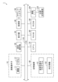
- FIG. 1 is a block diagram showing a configuration of an electronic musical instrument according to an embodiment of the present invention.
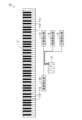
- FIG. 2 is a schematic diagram showing the configuration of a performance operator.
- FIG. 2 is a block diagram showing the configuration of a sound source unit.
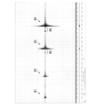
- FIG. 13 is a diagram showing a waveform of a pedal-off sound.
- 2 is a block diagram showing a configuration of functional sections of the electronic musical instrument;
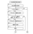
- FIG. 5 is a flowchart showing an example of a performance sound signal generation process executed by an electronic musical instrument.
- 5 is a flowchart showing an example of an additional sound signal generating process executed by an electronic musical instrument.
- 5 is a flowchart showing an example of an additional sound signal generating process executed by an electronic musical instrument.
- Fig. 1 is a block diagram showing the configuration of an electronic musical instrument according to an embodiment of the present invention.
- the electronic musical instrument 1 includes a performance operator 10, a setting operation section 20, a display 30, a sound source section 40, a sound system 50, a storage device 60, a CPU (Central Processing Unit) 70, a RAM (Random Access Memory) 80, a ROM (Read Only Memory) 90, a communication I/F (Interface) 100, and a bus 110.
- a performance operator 10 a setting operation section 20
- a display 30 a sound source section 40
- a sound system 50 a storage device 60
- a CPU Central Processing Unit
- RAM Random Access Memory
- ROM Read Only Memory
- communication I/F Interface
- the performance controls 10, the setting controls 20, the display 30, the sound source 40, the storage device 60, the CPU 70, the RAM 80, the ROM 90, and the communication I/F 100 are connected to the bus 110.
- An external device such as an external storage device 120 may also be connected to the bus 110 via the communication I/F 100.
- the performance controls 10 include a keyboard 11 and pedals 12 that are operated by the performer.
- the keyboard 11 may be an image of a keyboard displayed on the screen of a touch panel display, which will be described later.
- the pedals 12 are, for example, damper pedals.
- the setting operation unit 20 includes an operation switch that is operated on/off, an operation switch that is operated by rotating, or an operation switch that is operated by sliding, etc.
- the setting operation unit 20 is used to adjust the volume or perform various settings including turning the power on/off.
- the display 30 includes, for example, a liquid crystal display.
- the display 30 displays the name of the song, the musical score, or various other information.
- the display 30 may be a touch panel display. In this case, some or all of the performance controls 10 or the setting operation section 20 may be displayed on the display 30.
- the performer can instruct various operations by operating the display 30.
- the sound source unit 40 outputs audio data based on the pitch specified by the operation of the keyboard 11.
- the audio data is sampling data that indicates the waveform of the sound.
- the audio data output by the sound source unit 40 will be referred to as a sound signal.
- the sound system 50 includes a digital-to-analog (D/A) conversion circuit, an amplifier, and a speaker, converts the sound signal provided by the sound source unit 40 into an analog sound signal, and generates sound based on the analog sound signal.
- D/A digital-to-analog
- the storage device 60 includes a storage medium such as a hard disk, an optical disk, a magnetic disk, or a memory card, and prestores computer programs such as a sound signal generating program 61 and corresponding information 62, which will be described later.
- the CPU 70 executes the sound signal generating process, which will be described later, by executing the sound signal generating program 61 stored in the storage device 60.
- RAM 80 is, for example, a volatile memory, and is used as a working area for CPU 70, and temporarily stores various data.
- ROM 90 is, for example, a non-volatile memory, and stores control programs. ROM 90 may also store computer programs such as sound signal generating program 61.
- the sound signal generating program 61 may be provided in a form stored in a computer-readable recording medium and installed in the storage device 60 or ROM 90. Alternatively, the sound signal generating program 61 may be stored in the external storage device 120. In addition, when the communication I/F 100 is connected to a communication network, the sound signal generating program 61 distributed from a server connected to the communication network may be installed in the storage device 60 or ROM 90.
- FIG. 2 is a schematic diagram showing the configuration of the performance operator 10.
- the keyboard 11 has a plurality of keys 11a arranged in the left-right direction.
- the number of keys 11a on the keyboard 11 is 88, but the embodiment is not limited to this.
- the number of keys 11a on the keyboard 11 may be more or less than 88.
- the keys 11a are assigned pitches that increase in order from left to right.
- Each key 11a has the same function as a key with a damper on an acoustic piano such as a grand piano or upright piano. Therefore, when none of the keys 11a are pressed, control is performed in the same way as when the damper effect is acting on all of the keys 11a.
- the damper effect means that control is performed to produce the same effect as when a damper comes into contact with the string corresponding to each key on an acoustic piano.
- the pressed key 11a is controlled in the same way as when the damper effect is released.
- the damper effect is released, this means that the control is performed so that the same effect is achieved as when the damper is removed from the string corresponding to each key on an acoustic piano.
- the pedal 12 is placed at the performer's feet.
- the performer can operate the pedal 12 by stepping on it with his/her foot.
- the performer can also release the operation of the pedal 12 by removing his/her foot from the pedal 12.
- the position of the pedal 12 when it is not being operated is referred to as the "non-operated position”
- the position of the pedal 12 when it is being fully operated is referred to as the "maximum operation position.”
- a half-pedal area is provided between the non-operated position and the maximum operation position.
- the damper effect for all the keys 11a is released simultaneously. Specifically, by operating the pedal 12, the damper effect begins to be released at a position where the pedal 12 has moved a specified amount further back from the unoperated position. The position of the pedal 12 at this time is called the separation start position.
- the separation start position corresponds to the position of the pedal when the dampers begin to separate from all the strings on an acoustic piano. In this state, when the performer presses any of the keys 11a, a sympathetic sound (string sympathetic sound) based on all the pitches is generated.
- the damper effect comes into effect.
- the damper effect begins to come into effect at a position where the pedal 12 has moved a specified amount forward from the maximum operation position.
- the position of the pedal 12 at this time is called the contact start position.
- the contact start position corresponds to the position of the pedal when the damper begins to come into contact with all the strings on an acoustic piano.
- the separation start position and the contact start position are different from each other.
- the contact start position is approximately equal to the pedal position when the separation between all the strings and the damper ends when the pedal is operated on an acoustic piano (hereinafter referred to as the separation end position).
- the separation start position is also approximately equal to the pedal position when the contact between all the strings and the damper ends when the pedal operation on an acoustic piano is released (hereinafter referred to as the contact end position).
- the half pedal area is between the separation start position (contact end position) and the contact start position (separation end position).
- the pedal 12 is provided with position detection units 13, 14, an area detection unit 15, and a speed detection unit 16.
- Each position detection unit 13, 14 is, for example, a photoelectric sensor.
- Each position detection unit 13, 14 may also be a mechanical switch, etc.
- the position detection unit 13 detects that the pedal 12 is in an unoperated position.
- the position detection unit 14 detects that the pedal 12 is in a maximum operation position.
- the area detection unit 15 detects that the pedal 12 is in the half pedal area.
- the area detection unit 15 may be composed of multiple photoelectric sensors or mechanical switches.
- the area detection unit 15 may also detect that the pedal 12 is in a specific position in the half pedal area.
- the area detection unit 15 may be a single photoelectric sensor or a single mechanical switch.
- the specific position in the half pedal area may be, for example, the separation start position, the contact start position, or an intermediate position between these.
- the speed detection unit 16 is, for example, an optical Doppler sensor, and detects the speed of the pedal 12 when it passes through the half pedal region.
- the speed detection unit 16 may also detect the speed of the pedal 12 when it passes through a specific position in the half pedal region.
- the speed detection unit 16 may also be a sensor of another type capable of detecting speed, and may be configured integrally with the region detection unit 15.
- the detection results by the position detection units 13, 14, the region detection unit 15, and the speed detection unit 16 are used to control the output of sound signals.
- the above various positions or various speeds may be detected by the CPU 70, etc., based on a signal output by any of the detection units.
- FIG. 3 is a block diagram showing the configuration of sound source unit 40.
- sound source unit 40 includes a key press sound storage unit 41, a key press sound generation unit 42, a resonance sound generation unit 43, a pedal-off sound storage unit 44, a pedal-off sound generation unit 45, a pedal-on sound storage unit 46, and a pedal-on sound generation unit 47.
- the key press sound generation unit 42, the resonance sound generation unit 43, the pedal-off sound generation unit 45, and the pedal-on sound generation unit 47 may be realized by a CPU (not shown) provided in sound source unit 40 or the like, or may be realized by CPU 70 in Fig. 1.
- the key press sound storage unit 41 pre-stores key press sound waveform data that indicates the waveform of the key press sound when each key 11a of the keyboard 11 in FIG. 2 is pressed.
- Each key press sound waveform data is sampling data that represents a sound waveform, and is obtained by PCM (Pulse Code Modulation) recording the sound generated when each key of an acoustic piano is pressed.
- PCM Pulse Code Modulation
- the key press sound generating unit 42 generates and outputs a key press sound signal S1 from key press sound waveform data corresponding to the pressed key 11a stored in the key press sound storage unit 41.
- the key press sound signal S1 may be appropriately subjected to filtering to impart a change in tone, or envelope control to adjust the volume.
- the resonance sound generating unit 43 generates and outputs a resonance sound signal S2 indicating a resonance sound from the key press sound waveform data stored in the key press sound storage unit 41 based on the detection results by the position detection units 13 and 14 in FIG. 2.
- the pedal-off sound storage unit 44 includes two waveform storage units 44a and 44b.
- the waveform storage unit 44a and the waveform storage unit 44b store in advance pedal-off sound waveform data that indicates waveforms of different pedal-off sounds.
- the pedal-off sound is a sound that is generated in an acoustic piano when multiple strings collide with multiple dampers when the pedal operation is released.
- the pedal-off sound waveform data stored in the waveform storage units 44a and 44b respectively have different waveform shapes.
- the volume of the pedal-off sound of the pedal-off sound waveform data stored in the waveform storage unit 44b is greater than the volume of the pedal-off sound of the pedal-off sound waveform data stored in the waveform storage unit 44a.
- Each pedal-off sound waveform data may be generated by processing or synthesizing the key press sound waveform data so as to represent the vibration sound of the string when muted by the damper.
- each pedal-off sound waveform data may be generated by recording the physical sound of the string colliding with the damper.
- FIG. 4 is a diagram showing the waveform of a pedal-off sound.
- Waveform W1 is the waveform when the pedal-off speed is a first value.
- Waveform W2 is the waveform when the pedal-off speed is a second value that is greater than the first value.
- Waveform W3 is the waveform when the pedal-off speed is a third value that is greater than the second value.
- Waveform W4 is the waveform when the pedal-off speed is a fourth value that is greater than the third value.
- the pedal-off speed As shown in Figure 4, the greater the pedal-off speed, the greater the amplitude of the waveform of the pedal-off sound (i.e. the volume of the pedal-off sound). In contrast, the slower the pedal-off speed, the greater the volume of the so-called “mya sound.” In this respect, the pedal-off sound differs from the “mya sound.”
- the pedal-off sound also differs from the "mya sound” in that the pedal-off sound is generated by contact between the damper and the string, regardless of the vibration of the string, whereas the "mya sound" is generated only when the string is vibrating.
- pedal-off sound waveform data indicating waveforms W1 and W4 may be stored in waveform storage units 44a and 44b in FIG. 3, respectively.
- waveform W5, which appears immediately before waveform W3, and waveform W6, which appears immediately before waveform W4 are caused by the sound generated when the string and damper separate when the pedal is operated (hereinafter referred to as the pedal-on sound). Therefore, waveforms W5 and W6 are different from the waveform indicating the pedal-off sound.
- the pedal-off sound generating unit 45 in FIG. 3 generates and outputs a pedal-off sound signal S3 indicating the pedal-off sound when the operation of the pedal 12 in FIG. 2 is released from one or both of the pedal-off sound waveform data stored in the waveform storage units 44a and 44b.
- the generated pedal-off sound signal S3 differs depending on the pedal-off speed of the pedal 12.
- the pedal-on sound storage unit 46 pre-stores pedal-on sound waveform data that indicates the waveform of a pedal-on sound.
- the pedal-on sound waveform data may be generated by processing or synthesizing key press sound waveform data, similar to the pedal-off sound waveform data, or may be generated by recording the sound generated when the damper is released from the physical string.
- Pedal-on sound waveform data indicating waveform W5 or waveform W6 in FIG. 4 may be stored in the pedal-on sound storage unit 46.
- the pedal-on sound generating unit 47 generates and outputs a pedal-on sound signal S4 from the pedal-on sound waveform data stored in the pedal-on sound memory unit 46 based on the speed at which the pedal 12 moves when the pedal 12 is operated (hereinafter referred to as the pedal-on speed).
- the key press sound signal S1, the resonance sound signal S2, the pedal off sound signal S3 and the pedal on sound signal S4 may be output from a single output channel.
- the sound source unit 40 has multiple output channels (e.g., MIDI (Musical Instrument Digital Interface) channels)
- the key press sound signal S1, the resonance sound signal S2, the pedal off sound signal S3 and the pedal on sound signal S4 may be output from different output channels.
- Fig. 5 is a block diagram showing the configuration of the functional sections of the electronic musical instrument 1.
- the electronic musical instrument 1 includes, as functional section 2, a correspondence information acquisition section 3, a speed determination section 4, a sound determination section 5, a playback section 6, a recording section 7, and an announcing section 8.
- the functional section 2 of the electronic musical instrument 1 is realized by the CPU 70 in Fig. 1 executing a sound signal generating program 61 stored in a storage device 60 or the like. At least a part of the functional section 2 of the electronic musical instrument 1 may be realized by hardware such as an electronic circuit.
- the correspondence information acquisition unit 3 acquires the correspondence information 62 from the storage device 60.
- the correspondence information 62 indicates the correspondence relationship between the pedal-off speed and the volume of the pedal-off sound.
- the correspondence information 62 is table information that describes the relationship between the pedal-off speed and the volume of the pedal-off sound, but the embodiment is not limited to this.
- the correspondence information 62 may also be mathematical formula information for converting the pedal-off speed into the volume of the pedal-off sound.
- the speed determination unit 4 determines the pedal-on speed and pedal-off speed based on the movement speed of the pedal 12 detected by the speed detection unit 16.
- each of the pedal-on speed and pedal-off speed determined by the speed determination unit 4 is the speed at which the pedal 12 passes through the half pedal region.
- the sound determination unit 5 determines the volume of the pedal-off sound based on the correspondence information 62 acquired by the correspondence information acquisition unit 3 and the pedal-off speed determined by the speed determination unit 4.
- the playback unit 6 controls the operation of the sound source unit 40 to play various sounds. Specifically, in response to a key 11a on the keyboard 11 being pressed, the playback unit 6 controls the operation of the key press sound generating unit 42 (FIG. 3) of the sound source unit 40 to output a key press sound signal S1. The playback unit 6 also controls the operation of the resonance sound generating unit 43 (FIG. 3) of the sound source unit 40 to output a resonance sound signal S2 based on the position of the pedal 12 detected by the position detection units 13 and 14.
- the playback unit 6 controls the operation of the pedal-off sound generation unit 45 (FIG. 3) of the sound source unit 40 so as to output a pedal-off sound signal S3 indicating a pedal-off sound at the volume determined by the sound determination unit 5 at the timing when the region detection unit 15 detects that the pedal 12 is in the half pedal region. This causes the pedal-off sound to be played at the volume determined by the sound determination unit 5.
- the operation of the pedal-off sound generation unit 45 is controlled so that the pedal-off sound is played when it is detected that the pedal 12 is at the end of the half pedal region (contact end position) at the time of release of operation.
- the playback unit 6 controls the operation of the pedal-on sound generation unit 47 (FIG. 3) of the sound source unit 40 so as to output a pedal-on sound signal S4 at the timing when the area detection unit 15 detects that the pedal 12 is in the half pedal area.
- the playback unit 6 controls the operation of the pedal-on sound generation unit 47 so as not to output the pedal-on sound signal S4. In this way, a pedal-on sound is reproduced based on the pedal-on speed.
- the operation of the pedal-on sound generation unit 47 is controlled so that the pedal-on sound is reproduced when it is detected that the pedal 12 is at the end of the half pedal area (end of release position) during operation.
- the recording unit 7 records the history in the storage device 60 or the like.
- the history may be recorded in another storage medium, such as the external storage device 120 in FIG. 1.
- the performer can recognize after the fact that a pedal-off sound has been played by referring to the recorded playback history. This can encourage the performer to improve their playing technique.
- the notification unit 8 When the playback unit 6 plays a pedal-off sound at a volume equal to or greater than the volume threshold, or when the playback unit 6 plays a pedal-on sound, the notification unit 8 notifies the performer of this.
- the notification unit 8 issues a notification by causing the display 30 to display a character string indicating that a pedal-off sound at a volume equal to or greater than the volume threshold has been played, or that a pedal-on sound has been played, but the method of notification is not limited to this.
- the electronic musical instrument 1 includes an indicator light such as a lamp
- the notification unit 8 may issue a notification by turning the indicator light on, off, or flashing in a manner corresponding to the content of the notification.
- the sound signal generation process includes a performance sound signal generation process and an additional sound signal generation process.
- the performance sound signal generation process and the additional sound signal generation process are executed in parallel.
- Each of the performance sound signal generation process and the additional sound signal generation process will be described below with reference to the electronic musical instrument 1 in Fig. 5.
- In the initial state all the keys 11a of the keyboard 11 are in a released state, and the pedals 12 are in an unoperated state.
- FIG. 6 is a flow chart showing an example of a performance sound signal generation process executed by the electronic musical instrument 1.
- the playback unit 6 judges whether or not any of the keys 11a of the keyboard 11 has been pressed (step S11). If none of the keys 11a have been pressed, the playback unit 6 waits until one of the keys 11a is pressed. If one of the keys 11a has been pressed, the playback unit 6 judges whether or not the pedal 12 has been operated based on the detection results of the position detection units 13 and 14 (step S12). If the pedal 12 has been operated, a judgment is made as to whether or not to output a pedal-on sound signal S4, regardless of whether or not any of the keys 11a have been pressed. Details will be explained in steps S22 to S24 of the additional sound signal generation process in FIG. 7, which will be described later.
- step S13 If the pedal 12 is operated, the playback unit 6 controls the key press sound generating unit 42 and the resonance sound generating unit 43 of the sound source unit 40 to output the key press sound signal S1 and the resonance sound signal S2, respectively (step S13). Then, the process returns to step S11. If the pedal 12 is not operated in step S12, the playback unit 6 controls the key press sound generating unit 42 of the sound source unit 40 to output the key press sound signal S1 (step S14). Then, the process returns to step S11.
- step S21 acquires the correspondence information 62 from the storage device 60 or the like.
- step S22 determines whether or not the pedal 12 has been operated based on the detection results from the position detection units 13 and 14 (step S22). Step S22 is executed regardless of whether any of the keys 11a are pressed, and if any of the keys 11a are pressed, it is executed simultaneously with step S12 of the performance sound signal generation process in FIG. 6. If the pedal 12 is not operated, the speed determination unit 4 waits until the pedal 12 is operated.
- step S23 the speed determination unit 4 determines the pedal-on speed based on the detection result by the speed detection unit 16 (step S23). Next, the speed determination unit 4 determines whether the pedal-on speed determined in step S23 is equal to or greater than the speed threshold value (step S24). If the pedal-on speed is less than the speed threshold value, the process proceeds to step S28.
- Step S25 may be executed when the region detection unit 15 detects that the pedal 12 is in the half pedal region, in particular when it detects that the pedal 12 is in the release start position.
- the recording unit 7 also records a history indicating that the pedal-on sound has been reproduced in the storage device 60 or the like (step S26). Furthermore, the notification unit 8 notifies the performer that the pedal-on sound has been reproduced (step S27). Steps S25 to S27 may be performed either first or simultaneously. After that, the process proceeds to step S28.
- step S28 the speed determination unit 4 determines whether or not the operation of the pedal 12 has been released based on the detection results by the position detection units 13 and 14 (step S28). If the operation of the pedal 12 has not been released, the speed determination unit 4 waits until the operation of the pedal 12 is released.
- the speed determination unit 4 determines the pedal-off speed based on the detection result by the speed detection unit 16 (step S29).
- the sound determination unit 5 determines the volume of the pedal-off sound based on the correspondence information 62 acquired in step S21 and the pedal-off speed determined in step S29 (step S30).
- step S31 the playback unit 6 outputs a pedal-off sound signal S3 by controlling the pedal-off sound generating unit 45 of the sound source unit 40 (step S31).
- step S31 the pedal-off sound signal S3 is output so that the pedal-off sound of the volume determined in step S30 is played.
- Step S31 may be executed at the timing when the area detection unit 15 detects that the pedal 12 is in the half pedal area, in particular, at the timing when it is detected that the pedal 12 is in the contact start position.
- the sound determination unit 5 determines whether the volume of the pedal-off sound determined in step S30 is equal to or greater than the volume threshold (step S32). If the volume of the pedal-off sound is less than the volume threshold, the process returns to step S22.
- the recording unit 7 records in the storage device 60 or the like a history indicating that a pedal-off sound equal to or greater than the volume threshold has been played (step S33).
- the notification unit 8 notifies the performer that a pedal-off sound equal to or greater than the volume threshold has been played (step S34). Steps S33 and S34 may be executed either first or simultaneously. Processing then returns to step S22.
- the electronic musical instrument 1 of this embodiment includes the pedal 12, the speed detection unit 16 that detects the moving speed of the pedal 12, the speed determination unit 4 that determines the pedal-off speed when the operation of the pedal 12 is released based on the moving speed detected by the speed detection unit 16, and the playback unit 6 that plays a pedal-off sound based on the pedal-off speed determined by the speed determination unit 4.
- the pedal-off sound that occurs when the pedal operation on an acoustic instrument is released is simulated. This imparts the harshness of the sound generated in an acoustic instrument to the sound generated by the electronic instrument 1. As a result, the behavior of the electronic instrument 1 can be made to be closer to that of an acoustic instrument.
- the pedal-off sound is a sound that is undesirable to generate during normal performance. Therefore, by practicing in a way that does not generate the pedal-off sound on the electronic instrument, the performer can practice pedal operation when playing an acoustic instrument.
- the electronic musical instrument 1 may further include an area detection unit 15 that detects that the pedal 12 is in a specific area.
- the playback unit 6 may also play a pedal-off sound at the timing when the area detection unit 15 detects that the pedal 12 is in a specific area. In this case, the pedal-off sound is simulated at a predetermined timing when the operation of the pedal 12 is released. This makes it possible to make the behavior of the electronic musical instrument 1 closer to that of an acoustic musical instrument.
- the specific region may be between the position of the pedal 12 when not operated and the position of the pedal 12 when fully operated.
- the pedal-off sound is simulated at the timing when the pedal is released in an acoustic instrument and a pedal-off sound is generated. This makes it possible to make the behavior of the electronic musical instrument 1 closer to that of an acoustic instrument.
- the specific region is the contact start position, it is possible to make the behavior of the electronic musical instrument 1 even closer to that of an acoustic instrument.
- the pedal-off speed determined by the speed determination unit 4 may be the speed at which the pedal 12 passes through a specific area. In this case, the pedal-off sound of an acoustic instrument can be simulated with higher fidelity. In particular, if the pedal-off speed is the speed at which the pedal passes through the contact start position, the pedal-off sound of an acoustic instrument can be simulated with even higher fidelity.
- the electronic musical instrument 1 may further include a sound determination unit 5 that determines the volume of the pedal-off sound based on the pedal-off speed determined by the speed determination unit 4.
- the playback unit 6 may also play the pedal-off sound at the volume determined by the sound determination unit 5.
- the pedal-off sound of an acoustic musical instrument can be simulated with higher fidelity.
- the electronic musical instrument 1 may further include a correspondence information acquisition unit 3 that acquires correspondence information 62 indicating the correspondence relationship between the pedal-off speed and the volume of the pedal-off sound.
- the sound determination unit 5 may also determine the volume of the pedal-off sound based on the correspondence information 62 acquired by the correspondence information acquisition unit 3. In this case, the volume of the pedal-off sound can be easily determined based on the pedal-off speed.
- the speed determination unit 4 may further determine a pedal-on speed when the pedal 12 is operated, based on the moving speed detected by the speed detection unit 16.
- the playback unit 6 may further play a pedal-on sound based on the pedal-on speed determined by the speed determination unit 4. In this case, the pedal-on sound when the pedal 12 is operated in an acoustic instrument is further simulated. This makes it possible to make the behavior of the electronic musical instrument 1 closer to the behavior of an acoustic instrument.
- the pedal-on sound may be played when the region detection unit 15 detects that the pedal 12 is in the half-pedal region.
- the behavior of the electronic musical instrument 1 can be made to be closer to that of an acoustic musical instrument.
- the behavior of the electronic musical instrument 1 can be made to be even closer to that of an acoustic musical instrument.
- the pedal-on speed may be the speed at which the pedal 12 passes through the half-pedal region.
- the pedal-on sound of an acoustic instrument can be simulated with higher fidelity.
- the pedal-on speed is the speed at which the pedal passes through the release start position, the pedal-on sound of an acoustic instrument can be simulated with even higher fidelity.
- the electronic musical instrument 1 may be a keyboard instrument, and the pedal 12 may be a pedal for a keyboard instrument. In this case, the behavior of the electronic musical instrument 1 can be made to be closer to that of a keyboard instrument.
- the electronic musical instrument 1 may further include a recording unit 7 that records the playback history of an additional sound when an additional sound, such as a pedal-off sound, that is different from the played sound is played.
- an additional sound such as a pedal-off sound
- the performer can recognize after the fact that an additional sound has been played by referring to the recorded playback history. This can encourage the performer to improve their playing technique.
- the electronic musical instrument 1 may further include a notification unit 8 that notifies the player that an additional sound, such as a pedal-off sound, different from the sound being played, has been played. In this case, the player is notified so that he or she can recognize in real time that an additional sound has been played. This can encourage the player to improve their playing technique.
- a notification unit 8 that notifies the player that an additional sound, such as a pedal-off sound, different from the sound being played, has been played. In this case, the player is notified so that he or she can recognize in real time that an additional sound has been played. This can encourage the player to improve their playing technique.
- the sound determination unit 5 determines the volume of the pedal-off sound based on the pedal-off speed determined by the speed determination unit 4, and the playback unit 6 plays the pedal-off sound at the volume determined by the sound determination unit 5, but the embodiment is not limited to this.
- the sound determination unit 5 may determine the sound quality of the pedal-off sound based on the pedal-off speed determined by the speed determination unit 4, and the playback unit 6 may play the pedal-off sound with the sound quality determined by the sound determination unit 5.
- the waveform memory unit 44a and the waveform memory unit 44b of the pedal-off sound memory unit 44 store in advance pedal-off sound waveform data indicating waveforms of pedal-off sounds with different sound qualities.
- the correspondence information 62 may indicate the correspondence relationship between the pedal-off speed and the sound quality of the pedal-off sound.
- the sound determination unit 5 can easily determine the sound quality of the pedal-off sound based on the correspondence information 62 acquired by the correspondence information acquisition unit 3.
- the pedal-off sound storage unit 44 includes two waveform storage units 44a and 44b, but the embodiment is not limited to this.
- the pedal-off sound storage unit 44 may include three or more waveform storage units that each store different pedal-off sound waveform data in advance.
- the pedal-off sound generation unit 45 may select pedal-off sound waveform data corresponding to the pedal-off speed from the pedal-off sound waveform data stored in the multiple waveform storage units, and output the selected pedal-off sound waveform data as the pedal-off sound signal S3.
- the pedal-off sound is played back in accordance with the pedal-off speed, but the embodiment is not limited to this.
- the pedal-off sound is played back when the pedal-off speed is equal to or greater than a predetermined speed threshold, and may not be played back when the pedal-off speed is less than the speed threshold. That is, the playback unit 6 may play back the pedal-off sound based on the pedal-off speed determined by the speed determination unit 4.
- the electronic musical instrument 1 may not include the correspondence information acquisition unit 3 and the sound determination unit 5.
- the pedal-off sound storage unit 44 may include only one waveform storage unit, not multiple ones.
- the pedal-on sound is played when the pedal-on speed is equal to or greater than a speed threshold, and is not played when the pedal-on speed is less than the threshold, but the embodiment is not limited to this.
- the pedal-on sound may be played in accordance with the pedal-on speed.
- the pedal-on sound storage unit 46 pre-stores pedal-on sound waveform data indicating waveforms of multiple pedal-on sounds that are different from one another.
- the correspondence information 62 may indicate a correspondence relationship between the pedal-on speed and the pedal-on sound.
- the sound determination unit 5 can determine the pedal-on sound based on the correspondence information 62 acquired by the correspondence information acquisition unit 3. This allows the playback unit 6 to play back the pedal-on sound determined by the sound determination unit 5 so as to correspond to the pedal-on speed.
- the speed determination unit 4 determines the pedal-on speed and the playback unit 6 plays the pedal-on sound, but the embodiment is not limited to this.
- the speed determination unit 4 does not have to determine the pedal-on speed, and the playback unit 6 does not have to play the pedal-on sound.
- the sound source unit 40 does not include the pedal-on sound storage unit 46 and the pedal-on sound generation unit 47.
- the electronic musical instrument 1 includes the recording unit 7 and the notification unit 8, but the embodiment is not limited to this.
- the electronic musical instrument 1 does not have to include one or both of the recording unit 7 and the notification unit 8.
- the pedal 12 is a damper pedal, but the embodiment is not limited to this.
- the pedal 12 may be a pedal for other keyboard instruments.
- the pedal 12 may be a shift pedal.
- a PCM sound source is used that generates and outputs a sound signal based on waveform data, but the embodiment is not limited to this.
- a physical model sound source that calculates and outputs a sound signal based on a physical model may be used.
- the electronic musical instrument 1 includes the playback unit 6 that plays an additional sound such as a pedal-off sound or a pedal-on sound based on the pedal-off speed or pedal-on speed determined by the speed determination unit 4, but the embodiment is not limited to this. If the electronic musical instrument 1 includes the recording unit 7 or the notification unit 8, it does not have to include the playback unit 6.
- the recording unit 7 can record the generation history of additional sounds when the pedal-off speed determined by the speed determination unit 4 is equal to or greater than a predetermined speed threshold, or when the pedal-on speed is equal to or greater than a predetermined speed threshold. Therefore, the performer can recognize after the fact that an additional sound will be generated by referring to the recorded generation history. This can encourage the performer to improve their performance technique.
- the notification unit 8 can notify the performer that an additional sound will be generated when the pedal-off speed determined by the speed determination unit 4 is equal to or greater than a predetermined speed threshold, or when the pedal-on speed is equal to or greater than a predetermined speed threshold. Therefore, the performer can recognize in real time that an additional sound will be generated by being notified. This can encourage the performer to improve their performance technique.
- the electronic musical instrument according to the first embodiment is Pedals and a speed detection unit that detects a moving speed of the pedal; a speed determination unit that determines a pedal-off speed when the operation of the pedal is released, based on the moving speed detected by the speed detection unit; and a playback unit that plays a pedal-off sound based on the pedal-off speed determined by the speed determination unit.
- This electronic musical instrument simulates the pedal-off sound that occurs when the pedal operation on an acoustic musical instrument is released. This imparts the harshness of the sound generated by an acoustic musical instrument to the sound generated by the electronic musical instrument. As a result, the behavior of the electronic musical instrument can be made closer to that of an acoustic musical instrument.
- the electronic musical instrument a region detection unit that detects whether the pedal is in a specific region;
- the playback section may play a pedal-off sound at a timing when the area detection section detects that the pedal is in the specific area.
- the specific region may be between a position when the pedal is not operated and a position when the pedal is fully operated.
- the pedal-off sound is simulated at the same time that a pedal-off sound occurs when the pedal operation is released on an acoustic instrument. This makes it possible to make the behavior of the electronic musical instrument even closer to that of an acoustic musical instrument.
- the pedal-off speed determined by the speed determination unit may be a speed at which the pedal passes through the specific region.
- the pedal-off sound of an acoustic instrument can be simulated with greater fidelity.
- the electronic musical instrument according to any one of the above items 1 to 4, a sound determination unit that determines a volume or a quality of a pedal-off sound based on the pedal-off speed determined by the speed determination unit,
- the reproduction unit may reproduce a pedal-off sound at a volume or sound quality determined by the sound determination unit.
- the pedal-off sound of an acoustic instrument can be simulated with greater fidelity.
- a correspondence information acquisition unit that acquires correspondence information indicating a correspondence relationship between a pedal-off speed and a volume or a sound quality of a pedal-off sound
- the sound determination unit may determine a volume or a sound quality of a pedal-off sound based on the corresponding information acquired by the corresponding information acquisition unit.
- the volume or quality of the pedal-off sound can be easily determined based on the pedal-off speed.
- the speed determination unit further determines a pedal-on speed when the pedal is operated, based on the moving speed detected by the speed detection unit;
- the reproduction unit may further reproduce a pedal-on sound based on the pedal-on speed determined by the speed determination unit.
- the electronic musical instrument is a keyboard instrument
- the pedal may be a pedal for a keyboard instrument.
- the behavior of the electronic musical instrument can be made closer to that of a keyboard instrument.
Landscapes
- Physics & Mathematics (AREA)
- Engineering & Computer Science (AREA)
- Acoustics & Sound (AREA)
- Multimedia (AREA)
- Electrophonic Musical Instruments (AREA)
Abstract
電子楽器1は、ペダル12、速度検出部16、速度決定部4および再生部6を含む。速度検出部16は、ペダル12の移動速度を検出する。速度決定部4は、速度検出部16により検出された移動速度に基づいて、ペダル12の操作が解除されたときのペダルオフ速度を決定する。再生部6は、速度決定部4により決定されたペダルオフ速度に基づいてペダルオフ音を再生する。
Description
本発明は、電子楽器に関する。
アコースティック楽器においては、演奏操作により発生する演奏音以外にも雑音が発生する。近年、演奏音に加えて、アコースティック楽器に独特の雑音も模擬する電子楽器が開発されている。例えば、特許文献1には、複数の鍵からなる鍵盤およびダンパペダルを有する電子楽器が記載されている。
特許文献1の電子楽器においては、鍵が押鍵されることにより、その鍵に対応する直接音が発生する。ダンパペダルが踏み込まれている場合には、ダンパペダルの踏み込みおよび押鍵された鍵に対応する直接音とともに、ダンパペダルの踏み込みに対応するダンパノイズよりなる共振音が発生される。
アコースティック楽器においては、上記のダンパペダルの踏み込みにより発生するダンパノイズ以外にも、機械的な構造に起因した雑音が発生する。そのため、このような雑音を模擬することにより、電子楽器の挙動をアコースティック楽器の挙動に近づけることが望まれている。
本発明の目的は、アコースティック楽器に近い挙動を有する電子楽器を提供することである。
本発明の一局面に従う電子楽器は、ペダルと、前記ペダルの移動速度を検出する速度検出部と、前記速度検出部により検出された移動速度に基づいて、前記ペダルの操作が解除されたときのペダルオフ速度を決定する速度決定部と、前記速度決定部により決定されたペダルオフ速度に基づいてペダルオフ音を再生する再生部とを備える。
本発明によれば、電子楽器の挙動をアコースティック楽器の挙動に近づけることができる。
(1)電子楽器の構成
以下、本発明の実施の形態に係る電子楽器について図面を用いて詳細に説明する。電子楽器は、例えば電子鍵盤楽器である。図1は、本発明の一実施の形態に係る電子楽器の構成を示すブロック図である。図1に示すように、電子楽器1は、演奏操作子10、設定操作部20、表示器30、音源部40、サウンドシステム50、記憶装置60、CPU(中央演算処理装置)70、RAM(ランダムアクセスメモリ)80、ROM(リードオンリメモリ)90、通信I/F(インタフェース)100およびバス110を備える。
以下、本発明の実施の形態に係る電子楽器について図面を用いて詳細に説明する。電子楽器は、例えば電子鍵盤楽器である。図1は、本発明の一実施の形態に係る電子楽器の構成を示すブロック図である。図1に示すように、電子楽器1は、演奏操作子10、設定操作部20、表示器30、音源部40、サウンドシステム50、記憶装置60、CPU(中央演算処理装置)70、RAM(ランダムアクセスメモリ)80、ROM(リードオンリメモリ)90、通信I/F(インタフェース)100およびバス110を備える。
演奏操作子10、設定操作部20、表示器30、音源部40、記憶装置60、CPU70、RAM80、ROM90および通信I/F100は、バス110に接続される。外部記憶装置120等の外部機器が通信I/F100を介してバス110に接続されてもよい。
演奏操作子10は、演奏者により演奏操作される鍵盤11およびペダル12を含む。鍵盤11は、後述するタッチパネルディスプレイの画面上に表示された鍵盤の画像であってもよい。ペダル12は、例えばダンパペダルである。設定操作部20は、オン/オフ操作される操作スイッチ、回転操作される操作スイッチまたはスライド操作される操作スイッチ等を含む。設定操作部20は、音量の調整または電源のオン/オフを含む各種設定を行うために用いられる。
表示器30は、例えば液晶ディスプレイを含む。表示器30には、楽曲名、楽譜またはその他の各種情報が表示される。表示器30は、タッチパネルディスプレイであってもよい。この場合、演奏操作子10または設定操作部20の一部または全部が表示器30に表示されてもよい。演奏者は、表示器30を操作することにより各種操作を指示することができる。
音源部40は、鍵盤11の操作により指定される音高に基づいてオーディオデータを出力する。オーディオデータは、音の波形を示すサンプリングデータである。以下、音源部40により出力されるオーディオデータを音信号と呼ぶ。サウンドシステム50は、デジタルアナログ(D/A)変換回路、増幅器およびスピーカを含み、音源部40から与えられる音信号をアナログ音信号に変換し、アナログ音信号に基づく音を発生する。
記憶装置60は、ハードディスク、光学ディスク、磁気ディスクまたはメモリカード等の記憶媒体を含み、音信号発生プログラム61等のコンピュータプログラムおよび後述する対応情報62を予め記憶する。CPU70は、記憶装置60に記憶された音信号発生プログラム61を実行することにより後述する音信号発生処理を実行する。
RAM80は、例えば揮発性メモリからなり、CPU70の作業領域として用いられるとともに、各種データを一時的に記憶する。ROM90は、例えば不揮発性メモリからなり、制御プログラムを記憶する。ROM90は、音信号発生プログラム61等のコンピュータプログラムを記憶してもよい。
音信号発生プログラム61は、コンピュータが読み取り可能な記録媒体に格納された形態で提供され、記憶装置60またはROM90にインストールされてもよい。あるいは、音信号発生プログラム61は、外部記憶装置120に記憶されてもよい。また、通信I/F100が通信網に接続されている場合、通信網に接続されたサーバから配信された音信号発生プログラム61が記憶装置60またはROM90にインストールされてもよい。
(2)演奏操作子の構成
図2は、演奏操作子10の構成を示す模式図である。図2に示すように、鍵盤11は、左右方向に配列された複数の鍵11aを有する。本例では、鍵盤11における鍵11aの数は88であるが、実施の形態はこれに限定されない。鍵盤11における鍵11aの数は、88より多くてもよいし、88より少なくてもよい。複数の鍵11aには、左から右へ順に高くなる音高が対応付けられる。
図2は、演奏操作子10の構成を示す模式図である。図2に示すように、鍵盤11は、左右方向に配列された複数の鍵11aを有する。本例では、鍵盤11における鍵11aの数は88であるが、実施の形態はこれに限定されない。鍵盤11における鍵11aの数は、88より多くてもよいし、88より少なくてもよい。複数の鍵11aには、左から右へ順に高くなる音高が対応付けられる。
各鍵11aは、グランドピアノまたはアップライトピアノ等のアコースティックピアノにおけるダンパを有する鍵と同様の機能を有する。したがって、いずれの鍵11aも押鍵されていない状態においては、全部の鍵11aにダンパ効果が作用している状態と同様の制御が行われる。ダンパ効果が作用するとは、アコースティックピアノにおいて各鍵に対応する弦にダンパが接触した場合と同様の効果を奏するように制御が行われることを意味する。
一方、演奏者によりいずれかの鍵11aが押鍵された場合、押鍵された鍵11aについては、ダンパ効果が解除されている状態と同様の制御が行われる。ダンパ効果が解除されるとは、アコースティックピアノにおいて各鍵に対応する弦からダンパが離れた場合と同様の効果を奏するように制御が行われることを意味する。
ペダル12は、演奏者の足元に配置される。演奏者は、ペダル12を足で踏むことにより、ペダル12を操作することができる。また、演奏者は、ペダル12から足を離すことにより、ペダル12の操作を解除することができる。以下の説明では、ペダル12の未操作時の位置を未操作位置と呼び、ペダル12の最大操作時の位置を最大操作位置と呼ぶ。また、未操作位置と最大操作位置との間にハーフペダル領域が設けられる。
演奏者がペダル12を操作すると、全部の鍵11aに対するダンパ効果が一斉に解除される。具体的には、ペダル12が操作されることにより、ペダル12が未操作位置から所定量だけ奥に移動した位置で、ダンパ効果が解除され始める。このときのペダル12の位置を離間開始位置と呼ぶ。離間開始位置は、アコースティックピアノにおいて全部の弦からダンパが離れ始めるときのペダルの位置に対応する。この状態で、演奏者がいずれかの鍵11aを押鍵すると、全部の音高に基づく共鳴音(弦共鳴音)が発生する。
また、演奏者がペダル12の操作を解除すると、ダンパ効果が作用する。具体的には、ペダル12の操作が解除されることにより、ペダル12が最大操作位置から所定量だけ手前に移動した位置で、ダンパ効果が作用し始める。このときのペダル12の位置を接触開始位置と呼ぶ。接触開始位置は、アコースティックピアノにおいて全部の弦にダンパが接触し始めるときのペダルの位置に対応する。
離間開始位置と接触開始位置とは互いに異なる。なお、接触開始位置は、アコースティックピアノにおけるペダルの操作時に、全部の弦とダンパとの離間が終了するときのペダルの位置(以下、離間終了位置と呼ぶ。)と略等しい。また、離間開始位置は、アコースティックピアノにおけるペダルの操作の解除時に、全部の弦とダンパとの接触が終了するときのペダルの位置(以下、接触終了位置と呼ぶ。)と略等しい。ハーフペダル領域は、離間開始位置(接触終了位置)と接触開始位置(離間終了位置)との間にある。
ペダル12には、位置検出部13,14、領域検出部15および速度検出部16が設けられる。各位置検出部13,14は、例えば光電センサである。各位置検出部13,14は、機械的スイッチ等であってもよい。位置検出部13は、ペダル12が未操作位置にあることを検出する。位置検出部14は、ペダル12が最大操作位置にあることを検出する。
領域検出部15は、ペダル12がハーフペダル領域にあることを検出する。領域検出部15は、複数の光電センサまたは機械的スイッチにより構成されてもよい。また、領域検出部15は、ペダル12がハーフペダル領域における特定の位置にあることを検出してもよい。この場合、領域検出部15は、単一の光電センサまたは単一の機械的スイッチであってもよい。また、ハーフペダル領域における特定の位置は、例えば離間開始位置であってもよいし、接触開始位置であってもよいし、これらの中間の位置であってもよい。
速度検出部16は、例えば光学式ドップラセンサであり、ペダル12がハーフペダル領域を通過するときの速度を検出する。速度検出部16は、ペダル12がハーフペダル領域における特定の位置を通過するときの速度を検出してもよい。また、速度検出部16は、速度を検出可能な他の方式のセンサであってもよく、領域検出部15と一体的に構成されてもよい。位置検出部13,14、領域検出部15および速度検出部16による検出結果は、音信号の出力の制御に用いられる。なお、上記の各種位置または各種速度は、いずれかの検出部により出力される信号に基づいて、CPU70等により検出されてもよい。
(3)音源部の構成
図3は、音源部40の構成を示すブロック図である。図3に示すように、音源部40は、押鍵音記憶部41、押鍵音生成部42、共鳴音生成部43、ペダルオフ音記憶部44、ペダルオフ音生成部45、ペダルオン音記憶部46およびペダルオン音生成部47を含む。押鍵音生成部42、共鳴音生成部43、ペダルオフ音生成部45およびペダルオン音生成部47は、音源部40等に設けられた図示しないCPUにより実現されてもよいし、図1のCPU70により実現されてもよい。
図3は、音源部40の構成を示すブロック図である。図3に示すように、音源部40は、押鍵音記憶部41、押鍵音生成部42、共鳴音生成部43、ペダルオフ音記憶部44、ペダルオフ音生成部45、ペダルオン音記憶部46およびペダルオン音生成部47を含む。押鍵音生成部42、共鳴音生成部43、ペダルオフ音生成部45およびペダルオン音生成部47は、音源部40等に設けられた図示しないCPUにより実現されてもよいし、図1のCPU70により実現されてもよい。
押鍵音記憶部41は、図2の鍵盤11の各鍵11aが押鍵されたときの押鍵音の波形を示す押鍵音波形データを予め記憶する。各押鍵音波形データは、音の波形を表すサンプリングデータであり、アコースティックピアノの各鍵が押されたときに発生する音をPCM(Pulse Code Modulation)録音することにより得られる。本例では、88の弦にそれぞれ対応する88の押鍵音波形データが記憶されている。
押鍵音生成部42は、押鍵音記憶部41に記憶された、押鍵された鍵11aに対応する押鍵音波形データから押鍵音信号S1を生成し、出力する。押鍵音信号S1には、音色の変化を付与するためのフィルタ処理、または音量を調整するためのエンベロープ制御処理等が適宜行われてもよい。共鳴音生成部43は、図2の位置検出部13,14による検出結果に基づいて、押鍵音記憶部41に記憶された押鍵音波形データから共鳴音を示す共鳴音信号S2を生成し、出力する。
ペダルオフ音記憶部44は、2つの波形記憶部44a,44bを含む。波形記憶部44aと波形記憶部44bとは、互いに異なるペダルオフ音の波形を示すペダルオフ音波形データを予め記憶する。ペダルオフ音は、アコースティックピアノにおいて、ペダルの操作が解除されたときに複数の弦と複数のダンパとが衝突することにより発生する音である。
波形記憶部44a,44bにそれぞれ記憶されたペダルオフ音波形データは、互いに異なる波形の形状を有する。また、本例では、波形記憶部44bに記憶されたペダルオフ音波形データのペダルオフ音の音量は、波形記憶部44aに記憶されたペダルオフ音波形データのペダルオフ音の音量よりも大きい。各ペダルオフ音波形データは、ダンパによりミュートされるときの弦の振動音を示すように押鍵音波形データを加工または合成することにより生成されてもよい。あるいは、各ペダルオフ音波形データは、物理的な弦とダンパとの衝突音を録音することにより生成されてもよい。
図4は、ペダルオフ音の波形を示す図である。図4には、4の波形W1~W4が示される。以下の説明では、ペダル12の操作が解除されたときのペダル12の移動速度をペダルオフ速度と呼ぶ。波形W1は、ペダルオフ速度が第1の値であるときの波形である。波形W2は、ペダルオフ速度が第1の値よりも大きい第2の値であるときの波形である。波形W3は、ペダルオフ速度が第2の値よりも大きい第3の値であるときの波形である。波形W4は、ペダルオフ速度が第3の値よりも大きい第4の値であるときの波形である。
図4に示すように、ペダルオフ速度が大きいほどペダルオフ音の波形の振幅(すなわちペダルオフ音の音量)が大きい。これに対し、いわゆる「ミャー(mya)音」においては、ペダルオフ速度が小さいほど音量が大きい。この点で、ペダルオフ音は「ミャー音」とは異なる。また、ペダルオフ音は弦の振動とは無関係に、ダンパと弦との接触により発生するのに対し、「ミャー音」は弦の振動時にのみ発生するという点でも、ペダルオフ音は「ミャー音」とは異なる。
このように、複数の波形W1~W4にそれぞれ対応するペダルオフ音の音量は互いに異なる。そこで、例えば波形W1,W4を示すペダルオフ音波形データが図3の波形記憶部44a,44bにそれぞれ記憶されてもよい。なお、波形W3の直前に現れる波形W5、および波形W4の直前に現れる波形W6は、ペダルの操作時に、弦とダンパとが離れることにより発生する音(以下、ペダルオン音と呼ぶ。)に起因する。したがって、波形W5,W6は、ペダルオフ音を示す波形とは異なる。
図3のペダルオフ音生成部45は、波形記憶部44a,44bに記憶されたペダルオフ音波形データの一方または両方から、図2のペダル12の操作が解除されたときのペダルオフ音を示すペダルオフ音信号S3を生成し、出力する。生成されるペダルオフ音信号S3は、ペダル12のペダルオフ速度により異なる。
ペダルオン音記憶部46は、ペダルオン音の波形を示すペダルオン音波形データを予め記憶する。ペダルオン音波形データは、ペダルオフ音波形データと同様に、押鍵音波形データを加工または合成することにより生成されてもよいし、物理的な弦からダンパが離れるときの発生音を録音することにより生成されてもよい。図4の波形W5または波形W6を示すペダルオン音波形データがペダルオン音記憶部46に記憶されてもよい。
ペダルオン音生成部47は、ペダル12が操作されたときのペダル12の移動速度(以下、ペダルオン速度と呼ぶ。)に基づいて、ペダルオン音波形データをペダルオン音記憶部46からペダルオン音信号S4を生成し、出力する。
押鍵音信号S1、共鳴音信号S2、ペダルオフ音信号S3およびペダルオン音信号S4は、単一の出力チャンネルから出力されてもよい。一方で、音源部40が複数の出力チャンネル(例えばMIDI(Musical Instrument Digital Interface)チャンネル)を有する場合には、押鍵音信号S1、共鳴音信号S2、ペダルオフ音信号S3およびペダルオン音信号S4は、互いに異なる出力チャンネルから出力されてもよい。
(4)電子楽器の機能部
図5は、電子楽器1の機能部の構成を示すブロック図である。図5に示すように、電子楽器1は、機能部2として、対応情報取得部3、速度決定部4、音決定部5、再生部6、記録部7および報知部8を含む。図1のCPU70が記憶装置60等に記憶された音信号発生プログラム61を実行することにより、電子楽器1の機能部2が実現される。電子楽器1の機能部2の少なくとも一部は、電子回路等のハードウエアにより実現されてもよい。
図5は、電子楽器1の機能部の構成を示すブロック図である。図5に示すように、電子楽器1は、機能部2として、対応情報取得部3、速度決定部4、音決定部5、再生部6、記録部7および報知部8を含む。図1のCPU70が記憶装置60等に記憶された音信号発生プログラム61を実行することにより、電子楽器1の機能部2が実現される。電子楽器1の機能部2の少なくとも一部は、電子回路等のハードウエアにより実現されてもよい。
対応情報取得部3は、記憶装置60から対応情報62を取得する。対応情報62は、ペダルオフ速度とペダルオフ音の音量との対応関係を示す。本例では、対応情報62はペダルオフ速度とペダルオフ音の音量との関係が記載されたテーブル情報であるが、実施の形態はこれに限定されない。対応情報62は、ペダルオフ速度をペダルオフ音の音量に変換するための数式情報であってもよい。
速度決定部4は、速度検出部16により検出されたペダル12の移動速度に基づいて、ペダルオン速度およびペダルオフ速度を決定する。本例では、速度決定部4により決定されるペダルオン速度およびペダルオフ速度の各々は、ペダル12がハーフペダル領域を通過するときの速度である。音決定部5は、対応情報取得部3により取得された対応情報62と、速度決定部4により決定されたペダルオフ速度とに基づいて、ペダルオフ音の音量を決定する。
再生部6は、音源部40の動作を制御することにより、種々の音を再生する。具体的には、再生部6は、鍵盤11のいずれかの鍵11aが押鍵されることに応答して、押鍵音信号S1を出力するように音源部40の押鍵音生成部42(図3)の動作を制御する。また、再生部6は、位置検出部13,14により検出されるペダル12の位置に基づいて、共鳴音信号S2を出力するように音源部40の共鳴音生成部43(図3)の動作を制御する。
さらに、再生部6は、領域検出部15によりペダル12がハーフペダル領域にあることが検出されたタイミングで、音決定部5により決定された音量のペダルオフ音を示すペダルオフ音信号S3を出力するように音源部40のペダルオフ音生成部45(図3)の動作を制御する。これにより、音決定部5により決定された音量でペダルオフ音が再生される。本例では、ペダルオフ音は、ペダル12が操作解除時のハーフペダル領域の終端(接触終了位置)にあることが検出されたときに再生されるようにペダルオフ音生成部45の動作が制御される。
また、再生部6は、速度決定部4により決定されたペダルオン速度が予め定められた速度しきい値以上である場合、領域検出部15によりペダル12がハーフペダル領域にあることが検出されたタイミングで、ペダルオン音信号S4を出力するように音源部40のペダルオン音生成部47(図3)の動作を制御する。一方、再生部6は、ペダルオン速度が速度しきい値未満である場合、ペダルオン音信号S4を出力しないようにペダルオン音生成部47の動作を制御する。これにより、ペダルオン速度に基づいてペダルオン音が再生される。本例では、ペダルオン音は、ペダル12が操作時のハーフペダル領域の終端(離間終了位置)にあることが検出されたときに再生されるようにペダルオン音生成部47の動作が制御される。
記録部7は、再生部6により所定の音量しきい値以上の音量のペダルオフ音が再生された場合、または再生部6によりペダルオン音が再生された場合、その履歴を記憶装置60等に記録する。履歴は、図1の外部記憶装置120等の他の記憶媒体に記録されてもよい。この場合、演奏者は、記録された再生履歴を参照することにより、ペダルオフ音が再生されたことを事後的に認識することができる。これにより、演奏者に演奏技術の改善を促すことができる。
報知部8は、再生部6により音量しきい値以上の音量のペダルオフ音が再生された場合、または再生部6によりペダルオン音が再生された場合、その旨を演奏者に報知する。本例では、報知部8は、音量しきい値以上の音量のペダルオフ音が再生されたこと、またはペダルオン音が再生されたことを示す文字列を表示器30に表示させることにより報知を行うが、報知の方法はこれに限定されない。例えば、電子楽器1がランプ等の表示灯を含む場合、報知部8は、報知の内容に対応する態様で表示灯を点灯、消灯または点滅させることにより報知を行ってもよい。
(5)音信号発生処理
音信号発生処理は、演奏音信号発生処理と付加音信号発生処理とを含む。演奏音信号発生処理と付加音信号発生処理とは、並列的に実行される。以下、図5の電子楽器1を参照しつつ、演奏音信号発生処理および付加音信号発生処理の各々について説明する。なお、初期状態においては、鍵盤11の全ての鍵11aは離鍵状態にあり、ペダル12は未操作状態にあるとする。
音信号発生処理は、演奏音信号発生処理と付加音信号発生処理とを含む。演奏音信号発生処理と付加音信号発生処理とは、並列的に実行される。以下、図5の電子楽器1を参照しつつ、演奏音信号発生処理および付加音信号発生処理の各々について説明する。なお、初期状態においては、鍵盤11の全ての鍵11aは離鍵状態にあり、ペダル12は未操作状態にあるとする。
図6は、電子楽器1により実行される演奏音信号発生処理の一例を示すフローチャートである。まず、再生部6は、鍵盤11のいずれかの鍵11aが押鍵されたか否かを判定する(ステップS11)。いずれの鍵11aも押鍵されていない場合、再生部6は、いずれかの鍵11aが押鍵されるまで待機する。いずれかの鍵11aが押鍵された場合、再生部6は、位置検出部13,14による検出結果に基づいて、ペダル12が操作されたか否かを判定する(ステップS12)。なお、ペダル12が操作された場合には、いずれかの鍵11aが押鍵されたか否かに関わらず、ペダルオン音信号S4を出力するか否かの判定が行われる。詳細は、後述する図7の付加音信号発生処理のステップS22~S24で説明する。
ペダル12が操作された場合、再生部6は、音源部40の押鍵音生成部42および共鳴音生成部43を制御することにより、押鍵音信号S1および共鳴音信号S2をそれぞれ出力する(ステップS13)。その後、処理はステップS11に戻る。ステップS12でペダル12が操作されない場合、再生部6は、音源部40の押鍵音生成部42を制御することにより、押鍵音信号S1を出力する(ステップS14)。その後、処理はステップS11に戻る。
図7および図8は、電子楽器1により実行される付加音信号発生処理の一例を示すフローチャートである。まず、対応情報取得部3は、記憶装置60等から対応情報62を取得する(ステップS21)。次に、速度決定部4は、位置検出部13,14による検出結果に基づいて、ペダル12が操作されたか否かを判定する(ステップS22)。ステップS22は、いずれかの鍵11aが押鍵されているか否かとは無関係に実行され、いずれかの鍵11aが押鍵されている場合には、図6の演奏音信号発生処理のステップS12と同時に実行されることとなる。ペダル12が操作されていない場合、速度決定部4は、ペダル12が操作されるまで待機する。
ペダル12が操作された場合、速度決定部4は、速度検出部16による検出結果に基づいてペダルオン速度を決定する(ステップS23)。続いて、速度決定部4は、ステップS23で決定されたペダルオン速度が速度しきい値以上か否かを判定する(ステップS24)。ペダルオン速度が速度しきい値未満である場合、処理はステップS28に進む。
ペダルオン速度が速度しきい値以上である場合、再生部6は、音源部40のペダルオン音生成部47を制御することにより、ペダルオン音信号S4を出力する(ステップS25)。ステップS25は、領域検出部15によりペダル12がハーフペダル領域にあることが検出されたタイミング、特に、ペダル12が離間開始位置にあることが検出されたタイミングで実行されてもよい。
また、記録部7は、記憶装置60等にペダルオン音が再生されたことを示す履歴を記録する(ステップS26)。さらに、報知部8は、ペダルオン音が再生されたことを演奏者に報知する(ステップS27)。ステップS25~S27は、いずれが先に実行されてもよいし、同時に実行されてもよい。その後、処理はステップS28に進む。
ステップS28において、速度決定部4は、位置検出部13,14による検出結果に基づいて、ペダル12の操作が解除されたか否かを判定する(ステップS28)。ペダル12の操作が解除されていない場合、速度決定部4は、ペダル12の操作が解除されるまで待機する。
ペダル12の操作が解除された場合、速度決定部4は、速度検出部16による検出結果に基づいてペダルオフ速度を決定する(ステップS29)。次に、音決定部5は、ステップS21で取得された対応情報62と、ステップS29で決定されたペダルオフ速度とに基づいてペダルオフ音の音量を決定する(ステップS30)。
その後、再生部6は、音源部40のペダルオフ音生成部45を制御することにより、ペダルオフ音信号S3を出力する(ステップS31)。ステップS31では、ステップS30で決定された音量のペダルオフ音が再生されるようにペダルオフ音信号S3が出力される。ステップS31は、領域検出部15によりペダル12がハーフペダル領域にあることが検出されたタイミング、特に、ペダル12が接触開始位置にあることが検出されたタイミングで実行されてもよい。
次に、音決定部5は、ステップS30で決定されたペダルオフ音の音量が音量しきい値以上であるか否かを判定する(ステップS32)。ペダルオフ音の音量が音量しきい値未満である場合、処理はステップS22に戻る。
ペダルオフ音の音量が音量しきい値以上である場合、記録部7は、記憶装置60等に音量しきい値以上のペダルオフ音が再生されたことを示す履歴を記録する(ステップS33)。また、報知部8は、音量しきい値以上のペダルオフ音が再生されたことを演奏者に報知する(ステップS34)。ステップS33,S34は、いずれが先に実行されてもよいし、同時に実行されてもよい。その後、処理はステップS22に戻る。
(6)効果
以上説明したように、本実施の形態に係る電子楽器1は、ペダル12と、ペダル12の移動速度を検出する速度検出部16と、速度検出部16により検出された移動速度に基づいて、ペダル12の操作が解除されたときのペダルオフ速度を決定する速度決定部4と、速度決定部4により決定されたペダルオフ速度に基づいてペダルオフ音を再生する再生部6とを備える。
以上説明したように、本実施の形態に係る電子楽器1は、ペダル12と、ペダル12の移動速度を検出する速度検出部16と、速度検出部16により検出された移動速度に基づいて、ペダル12の操作が解除されたときのペダルオフ速度を決定する速度決定部4と、速度決定部4により決定されたペダルオフ速度に基づいてペダルオフ音を再生する再生部6とを備える。
この構成によれば、アコースティック楽器においてペダルの操作が解除されたときのペダルオフ音が模擬される。これにより、アコースティック楽器における発生音の雑味が電子楽器1の発生音に付与される。その結果、電子楽器1の挙動をアコースティック楽器の挙動に近づけることができる。なお、ペダルオフ音は、通常の演奏では発生させることが好ましくない音である。したがって、演奏者は、電子楽器においてペダルオフ音を発生させないように練習することにより、アコースティック楽器を演奏する際のペダル操作の練習を行うことができる。
電子楽器1は、ペダル12が特定の領域にあることを検出する領域検出部15をさらに備えてもよい。また、再生部6は、領域検出部15によりペダル12が特定の領域にあることが検出されたタイミングでペダルオフ音を再生してもよい。この場合、ペダル12の操作が解除されたときに所定のタイミングでペダルオフ音が模擬される。これにより、電子楽器1の挙動をアコースティック楽器の挙動により近づけることができる。
特定の領域は、ペダル12の未操作時の位置と、ペダル12の最大操作時の位置との間にあってもよい。この場合、アコースティック楽器においてペダルの操作が解除されたときにペダルオフ音が発生するタイミングでペダルオフ音が模擬される。これにより、電子楽器1の挙動をアコースティック楽器の挙動により近づけることができる。特に、特定の領域が接触開始位置である場合には、電子楽器1の挙動をアコースティック楽器の挙動にさらに近づけることができる。
速度決定部4により決定されたペダルオフ速度は、ペダル12が特定の領域を通過するときの速度であってもよい。この場合、アコースティック楽器におけるペダルオフ音をより高い忠実度で模擬することができる。特に、ペダルオフ速度が接触開始位置を通過するときの速度である場合には、アコースティック楽器におけるペダルオフ音をさらに高い忠実度で模擬することができる。
電子楽器1は、速度決定部4により決定されたペダルオフ速度に基づいてペダルオフ音の音量を決定する音決定部5をさらに備えてもよい。また、再生部6は、音決定部5により決定された音量でペダルオフ音を再生してもよい。この場合、アコースティック楽器におけるペダルオフ音をより高い忠実度で模擬することができる。
電子楽器1は、ペダルオフ速度とペダルオフ音の音量との対応関係を示す対応情報62を取得する対応情報取得部3をさらに備えてもよい。また、音決定部5は、対応情報取得部3により取得された対応情報62に基づいてペダルオフ音の音量を決定してもよい。この場合、ペダルオフ速度に基づいてペダルオフ音の音量を容易に決定することができる。
速度決定部4は、速度検出部16により検出された移動速度に基づいて、ペダル12が操作されたときのペダルオン速度をさらに決定してもよい。また、再生部6は、速度決定部4により決定されたペダルオン速度に基づいてペダルオン音をさらに再生してもよい。この場合、アコースティック楽器においてペダル12が操作されたときのペダルオン音がさらに模擬される。これにより、電子楽器1の挙動をアコースティック楽器の挙動により近づけることができる。
ペダルオン音は、領域検出部15によりペダル12がハーフペダル領域にあることが検出されたタイミングで再生されてもよい。この場合、電子楽器1の挙動をアコースティック楽器の挙動により近づけることができる。特に、特定の領域が離間開始位置である場合には、電子楽器1の挙動をアコースティック楽器の挙動にさらに近づけることができる。
ペダルオン速度は、ペダル12がハーフペダル領域を通過するときの速度であってもよい。この場合、アコースティック楽器におけるペダルオン音をより高い忠実度で模擬することができる。特に、ペダルオン速度が離間開始位置を通過するときの速度である場合には、アコースティック楽器におけるペダルオン音をさらに高い忠実度で模擬することができる。
電子楽器1は鍵盤楽器であり、ペダル12は鍵盤楽器用のペダルであってもよい。この場合、電子楽器1の挙動を鍵盤楽器の挙動に近づけることができる。
電子楽器1は、演奏音とは異なるペダルオフ音等の付加音が再生された場合、付加音の再生履歴を記録する記録部7をさらに備えてもよい。この場合、演奏者は、記録された再生履歴を参照することにより、付加音が再生されたことを事後的に認識することができる。これにより、演奏者に演奏技術の改善を促すことができる。
電子楽器1は、演奏音とは異なるペダルオフ音等の付加音が再生された場合、付加音が再生されたことを報知する報知部8をさらに備えてもよい。この場合、演奏者は、報知が行われることにより、付加音が再生されたことをリアルタイムに認識することができる。これにより、演奏者に演奏技術の改善を促すことができる。
(7)他の実施の形態
(a)上記実施の形態において、音決定部5は速度決定部4により決定されたペダルオフ速度に基づいてペダルオフ音の音量を決定し、再生部6は音決定部5により決定された音量でペダルオフ音を再生するが、実施の形態はこれに限定されない。音決定部5は速度決定部4により決定されたペダルオフ速度に基づいてペダルオフ音の音質を決定し、再生部6は音決定部5により決定された音質でペダルオフ音を再生してもよい。
(a)上記実施の形態において、音決定部5は速度決定部4により決定されたペダルオフ速度に基づいてペダルオフ音の音量を決定し、再生部6は音決定部5により決定された音量でペダルオフ音を再生するが、実施の形態はこれに限定されない。音決定部5は速度決定部4により決定されたペダルオフ速度に基づいてペダルオフ音の音質を決定し、再生部6は音決定部5により決定された音質でペダルオフ音を再生してもよい。
この構成においては、ペダルオフ音記憶部44の波形記憶部44aと波形記憶部44bとは、互いに異なる音質のペダルオフ音の波形を示すペダルオフ音波形データを予め記憶する。また、対応情報62は、ペダルオフ速度とペダルオフ音の音質との対応関係を示してもよい。この場合、音決定部5は、対応情報取得部3により取得された対応情報62に基づいて、ペダルオフ音の音質を容易に決定することができる。
(b)上記実施の形態において、ペダルオフ音記憶部44は2つの波形記憶部44a,44bを含むが、実施の形態はこれに限定されない。ペダルオフ音記憶部44は、互いに異なるペダルオフ音波形データをそれぞれ予め記憶する3つ以上の波形記憶部を含んでもよい。また、ペダルオフ音生成部45は、複数の波形記憶部に記憶されたペダルオフ音波形データのうち、ペダルオフ速度に対応するペダルオフ音波形データを選択し、選択されたペダルオフ音波形データをペダルオフ音信号S3として出力してもよい。
(c)上記実施の形態において、ペダルオフ音はペダルオフ速度に対応して再生されるが、実施の形態はこれに限定されない。ペダルオン音と同様に、ペダルオフ音は、ペダルオフ速度が予め定められた速度しきい値以上である場合に再生され、ペダルオフ速度が速度しきい値未満である場合には再生されなくてもよい。すなわち、再生部6は、速度決定部4により決定されたペダルオフ速度に基づいてペダルオフ音を再生してもよい。この場合、電子楽器1は、対応情報取得部3および音決定部5を含まなくてもよい。また、ペダルオフ音記憶部44は、複数ではなく1つの波形記憶部を含めばよい。
(d)上記実施の形態において、ペダルオン音は、ペダルオン速度が速度しきい値以上である場合に再生され、ペダルオン速度がしきい値未満である場合には再生されないが、実施の形態はこれに限定されない。ペダルオフ音と同様に、ペダルオン音は、ペダルオン速度に対応して再生されてもよい。
この構成においては、ペダルオン音記憶部46は、互いに異なる複数のペダルオン音の波形を示すペダルオン音波形データを予め記憶する。また、対応情報62は、ペダルオン速度とペダルオン音との対応関係を示してもよい。この場合、音決定部5は、対応情報取得部3により取得された対応情報62に基づいて、ペダルオン音を決定することができる。これにより、再生部6は、ペダルオン速度に対応するように音決定部5により決定されたペダルオン音を再生することができる。
(e)上記実施の形態において、速度決定部4はペダルオン速度を決定し、再生部6はペダルオン音を再生するが、実施の形態はこれに限定されない。速度決定部4はペダルオン速度を決定しなくてもよく、再生部6はペダルオン音を再生しなくてもよい。この場合、音源部40は、ペダルオン音記憶部46およびペダルオン音生成部47を含まない。
(f)上記実施の形態において、電子楽器1は記録部7および報知部8を含むが、実施の形態はこれに限定されない。電子楽器1は、記録部7および報知部8の一方または両方を含まなくてもよい。
(g)上記実施の形態において、ペダル12はダンパペダルであるが、実施の形態はこれに限定されない。ペダル12は、他の鍵盤楽器用のペダルであってもよい。例えば、アコースティック楽器においては、シフトペダルが操作された場合、またはシフトペダルの操作が解除された場合、鍵盤およびアクション等が設けられた棚板が左右方向に移動することにより、側板との衝突音が発生することがある。そのため、ペダル12は、シフトペダルであってもよい。
(h)上記実施の形態において、波形データに基づいて音信号生成して出力するPCM音源が用いられるが、実施の形態はこれに限定されない。PCM音源に代えて、物理モデルに基づいて音信号を演算して出力する物理モデル音源が用いられてもよい。
(8)参考形態
上記実施の形態において、電子楽器1は速度決定部4により決定されたペダルオフ速度またはペダルオン速度に基づいてペダルオフ音またはペダルオン音等の付加音を再生する再生部6を含むが、実施の形態はこれに限定されない。電子楽器1が記録部7または報知部8を含む場合には、再生部6を含まなくてもよい。
上記実施の形態において、電子楽器1は速度決定部4により決定されたペダルオフ速度またはペダルオン速度に基づいてペダルオフ音またはペダルオン音等の付加音を再生する再生部6を含むが、実施の形態はこれに限定されない。電子楽器1が記録部7または報知部8を含む場合には、再生部6を含まなくてもよい。
この構成においても、記録部7は、速度決定部4により決定されたペダルオフ速度が所定の速度しきい値以上である場合、またはペダルオン速度が所定の速度しきい値以上である場合等に、付加音の発生履歴を記録することが可能である。そのため、演奏者は、記録された発生履歴を参照することにより、付加音が発生することを事後的に認識することができる。これにより、演奏者に演奏技術の改善を促すことができる。
同様に、報知部8は、速度決定部4により決定されたペダルオフ速度が所定の速度しきい値以上である場合、またはペダルオン速度が所定の速度しきい値以上である場合等に、付加音が発生することを演奏者に報知することが可能である。そのため、演奏者は、報知が行われることにより、付加音が発生することをリアルタイムに認識することができる。これにより、演奏者に演奏技術の改善を促すことができる。
(9)実施の形態の総括
(第1項)第1項に係る電子楽器は、
ペダルと、
前記ペダルの移動速度を検出する速度検出部と、
前記速度検出部により検出された移動速度に基づいて、前記ペダルの操作が解除されたときのペダルオフ速度を決定する速度決定部と、
前記速度決定部により決定されたペダルオフ速度に基づいてペダルオフ音を再生する再生部とを備える。
(第1項)第1項に係る電子楽器は、
ペダルと、
前記ペダルの移動速度を検出する速度検出部と、
前記速度検出部により検出された移動速度に基づいて、前記ペダルの操作が解除されたときのペダルオフ速度を決定する速度決定部と、
前記速度決定部により決定されたペダルオフ速度に基づいてペダルオフ音を再生する再生部とを備える。
この電子楽器によれば、アコースティック楽器においてペダルの操作が解除されたときのペダルオフ音が模擬される。これにより、アコースティック楽器における発生音の雑味が電子楽器の発生音に付与される。その結果、電子楽器の挙動をアコースティック楽器の挙動に近づけることができる。
(第2項)第1項に記載の電子楽器は、
前記ペダルが特定の領域にあることを検出する領域検出部をさらに備え、
前記再生部は、前記領域検出部により前記ペダルが前記特定の領域にあることが検出されたタイミングでペダルオフ音を再生してもよい。
前記ペダルが特定の領域にあることを検出する領域検出部をさらに備え、
前記再生部は、前記領域検出部により前記ペダルが前記特定の領域にあることが検出されたタイミングでペダルオフ音を再生してもよい。
この場合、ペダルの操作が解除されたときに所定のタイミングでペダルオフ音が模擬される。これにより、電子楽器の挙動をアコースティック楽器の挙動により近づけることができる。
(第3項)第2項に記載の電子楽器において、
前記特定の領域は、前記ペダルの未操作時の位置と、前記ペダルの最大操作時の位置との間にあってもよい。
前記特定の領域は、前記ペダルの未操作時の位置と、前記ペダルの最大操作時の位置との間にあってもよい。
この場合、アコースティック楽器においてペダルの操作が解除されたときにペダルオフ音が発生するタイミングでペダルオフ音が模擬される。これにより、電子楽器の挙動をアコースティック楽器の挙動にさらに近づけることができる。
(第4項)第2項または第3項に記載の電子楽器において、
前記速度決定部により決定されたペダルオフ速度は、前記ペダルが前記特定の領域を通過するときの速度であってもよい。
前記速度決定部により決定されたペダルオフ速度は、前記ペダルが前記特定の領域を通過するときの速度であってもよい。
この場合、アコースティック楽器におけるペダルオフ音をより高い忠実度で模擬することができる。
(第5項)第1項~第4項のいずれか一項に記載の電子楽器は、
前記速度決定部により決定されたペダルオフ速度に基づいてペダルオフ音の音量または音質を決定する音決定部をさらに備え、
前記再生部は、前記音決定部により決定された音量または音質でペダルオフ音を再生してもよい。
前記速度決定部により決定されたペダルオフ速度に基づいてペダルオフ音の音量または音質を決定する音決定部をさらに備え、
前記再生部は、前記音決定部により決定された音量または音質でペダルオフ音を再生してもよい。
この場合、アコースティック楽器におけるペダルオフ音をより高い忠実度で模擬することができる。
(第6項)第5項に記載の電子楽器は、
ペダルオフ速度とペダルオフ音の音量または音質との対応関係を示す対応情報を取得する対応情報取得部をさらに備え、
前記音決定部は、前記対応情報取得部により取得された対応情報に基づいてペダルオフ音の音量または音質を決定してもよい。
ペダルオフ速度とペダルオフ音の音量または音質との対応関係を示す対応情報を取得する対応情報取得部をさらに備え、
前記音決定部は、前記対応情報取得部により取得された対応情報に基づいてペダルオフ音の音量または音質を決定してもよい。
この場合、ペダルオフ速度に基づいてペダルオフ音の音量または音質を容易に決定することができる。
(第7項)第1項~第6項のいずれか一項に記載の電子楽器において、
前記速度決定部は、前記速度検出部により検出された移動速度に基づいて、前記ペダルが操作されたときのペダルオン速度をさらに決定し、
前記再生部は、前記速度決定部により決定されたペダルオン速度に基づいてペダルオン音をさらに再生してもよい。
前記速度決定部は、前記速度検出部により検出された移動速度に基づいて、前記ペダルが操作されたときのペダルオン速度をさらに決定し、
前記再生部は、前記速度決定部により決定されたペダルオン速度に基づいてペダルオン音をさらに再生してもよい。
この場合、アコースティック楽器においてペダルが操作されたときのペダルオン音がさらに模擬される。これにより、電子楽器の挙動をアコースティック楽器の挙動により近づけることができる。
(第8項)第1項~第7項のいずれか一項に記載の電子楽器において、
前記電子楽器は鍵盤楽器であり、
前記ペダルは鍵盤楽器用のペダルであってもよい。
前記電子楽器は鍵盤楽器であり、
前記ペダルは鍵盤楽器用のペダルであってもよい。
この場合、電子楽器の挙動を鍵盤楽器の挙動に近づけることができる。
1…電子楽器,2…機能部,3…対応情報取得部,4…速度決定部,5…音決定部,6…再生部,7…記録部,8…報知部,10…演奏操作子,11…鍵盤,11a…鍵,12…ペダル,13,14…位置検出部,15…領域検出部,16…速度検出部,20…設定操作部,30…表示器,40…音源部,41…押鍵音記憶部,42…押鍵音生成部,43…共鳴音生成部,44…ペダルオフ音記憶部,44a,44b…波形記憶部,45…ペダルオフ音生成部,46…ペダルオン音記憶部,47…ペダルオン音生成部,50…サウンドシステム,60…記憶装置,61…音信号発生プログラム,62…対応情報,70…CPU,80…RAM,90…ROM,100…通信I/F,110…バス,120…外部記憶装置,S1…押鍵音信号,S2…共鳴音信号,S3…ペダルオフ音信号,S4…ペダルオン音信号,W1~W6…波形
Claims (8)
- ペダルと、
前記ペダルの移動速度を検出する速度検出部と、
前記速度検出部により検出された移動速度に基づいて、前記ペダルの操作が解除されたときのペダルオフ速度を決定する速度決定部と、
前記速度決定部により決定されたペダルオフ速度に基づいてペダルオフ音を再生する再生部とを備える、電子楽器。 - 前記ペダルが特定の領域にあることを検出する領域検出部をさらに備え、
前記再生部は、前記領域検出部により前記ペダルが前記特定の領域にあることが検出されたタイミングでペダルオフ音を再生する、請求項1記載の電子楽器。 - 前記特定の領域は、前記ペダルの未操作時の位置と、前記ペダルの最大操作時の位置との間にある、請求項2記載の電子楽器。
- 前記速度決定部により決定されたペダルオフ速度は、前記ペダルが前記特定の領域を通過するときの速度である、請求項2または3記載の電子楽器。
- 前記速度決定部により決定されたペダルオフ速度に基づいてペダルオフ音の音量または音質を決定する音決定部をさらに備え、
前記再生部は、前記音決定部により決定された音量または音質でペダルオフ音を再生する、請求項1~3のいずれか一項に記載の電子楽器。 - ペダルオフ速度とペダルオフ音の音量または音質との対応関係を示す対応情報を取得する対応情報取得部をさらに備え、
前記音決定部は、前記対応情報取得部により取得された対応情報に基づいてペダルオフ音の音量または音質を決定する、請求項5記載の電子楽器。 - 前記速度決定部は、前記速度検出部により検出された移動速度に基づいて、前記ペダルが操作されたときのペダルオン速度をさらに決定し、
前記再生部は、前記速度決定部により決定されたペダルオン速度に基づいてペダルオン音をさらに再生する、請求項1~3のいずれか一項に記載の電子楽器。 - 前記電子楽器は鍵盤楽器であり、
前記ペダルは鍵盤楽器用のペダルである、請求項1~3のいずれか一項に記載の電子楽器。
Applications Claiming Priority (2)
| Application Number | Priority Date | Filing Date | Title |
|---|---|---|---|
| JP2023-111671 | 2023-07-06 | ||
| JP2023111671A JP2025008991A (ja) | 2023-07-06 | 2023-07-06 | 電子楽器 |
Publications (1)
| Publication Number | Publication Date |
|---|---|
| WO2025009359A1 true WO2025009359A1 (ja) | 2025-01-09 |
Family
ID=94171682
Family Applications (1)
| Application Number | Title | Priority Date | Filing Date |
|---|---|---|---|
| PCT/JP2024/021649 Ceased WO2025009359A1 (ja) | 2023-07-06 | 2024-06-14 | 電子楽器 |
Country Status (2)
| Country | Link |
|---|---|
| JP (1) | JP2025008991A (ja) |
| WO (1) | WO2025009359A1 (ja) |
Citations (4)
| Publication number | Priority date | Publication date | Assignee | Title |
|---|---|---|---|---|
| JPH03174590A (ja) * | 1989-12-04 | 1991-07-29 | Kawai Musical Instr Mfg Co Ltd | 電子楽器 |
| JPH05188950A (ja) * | 1992-01-08 | 1993-07-30 | Matsushita Electric Ind Co Ltd | 電子楽器 |
| JPH10319963A (ja) * | 1997-05-20 | 1998-12-04 | Kawai Musical Instr Mfg Co Ltd | 電子楽器 |
| JP2001005458A (ja) * | 1992-06-09 | 2001-01-12 | Yamaha Corp | 鍵盤楽器 |
-
2023
- 2023-07-06 JP JP2023111671A patent/JP2025008991A/ja active Pending
-
2024
- 2024-06-14 WO PCT/JP2024/021649 patent/WO2025009359A1/ja not_active Ceased
Patent Citations (4)
| Publication number | Priority date | Publication date | Assignee | Title |
|---|---|---|---|---|
| JPH03174590A (ja) * | 1989-12-04 | 1991-07-29 | Kawai Musical Instr Mfg Co Ltd | 電子楽器 |
| JPH05188950A (ja) * | 1992-01-08 | 1993-07-30 | Matsushita Electric Ind Co Ltd | 電子楽器 |
| JP2001005458A (ja) * | 1992-06-09 | 2001-01-12 | Yamaha Corp | 鍵盤楽器 |
| JPH10319963A (ja) * | 1997-05-20 | 1998-12-04 | Kawai Musical Instr Mfg Co Ltd | 電子楽器 |
Also Published As
| Publication number | Publication date |
|---|---|
| JP2025008991A (ja) | 2025-01-20 |
Similar Documents
| Publication | Publication Date | Title |
|---|---|---|
| JP5119932B2 (ja) | 鍵盤楽器、ピアノおよび自動演奏ピアノ | |
| JP4608718B2 (ja) | 楽器 | |
| JP2000132164A (ja) | 対話式ドラムレッスン装置と方法 | |
| CN103514870B (zh) | 电子键盘乐器及方法 | |
| JPH05188950A (ja) | 電子楽器 | |
| JP7230413B2 (ja) | 音信号発生装置、音信号発生方法および音信号発生プログラム | |
| JP2009156914A (ja) | 自動伴奏装置及びプログラム | |
| JP4131278B2 (ja) | 鍵盤楽器用力覚制御装置 | |
| CN111009231B (zh) | 共鸣音信号产生装置及方法、介质以及电子音乐装置 | |
| JP7476501B2 (ja) | 共鳴音信号発生方法、共鳴音信号発生装置、共鳴音信号発生プログラムおよび電子音楽装置 | |
| JP2025008991A (ja) | 電子楽器 | |
| JP2001005458A (ja) | 鍵盤楽器 | |
| JP2004294832A (ja) | 電子ピアノのペダル効果生成装置 | |
| JP2011013445A (ja) | 電子楽器 | |
| JP4315116B2 (ja) | 電子音楽装置 | |
| JP3461916B2 (ja) | 電子楽器 | |
| JP6394737B2 (ja) | 電子鍵盤楽器、方法及びプログラム | |
| JP3755528B2 (ja) | 鍵盤用力覚制御装置および記憶媒体 | |
| JP3852441B2 (ja) | 鍵盤用力覚制御装置および記憶媒体 | |
| JP2005352513A (ja) | 鍵盤楽器 | |
| CN117437898A (zh) | 音输出系统 | |
| JP2016061846A (ja) | 電子鍵盤楽器、駆動方法及びプログラム | |
| JPH09152881A (ja) | 通信カラオケ装置のコーラス音の再生方法 | |
| JP2006301017A (ja) | 電子鍵盤楽器 | |
| JP2002318582A (ja) | 楽音情報割当操作子を有する電子音楽装置 |
Legal Events
| Date | Code | Title | Description |
|---|---|---|---|
| 121 | Ep: the epo has been informed by wipo that ep was designated in this application |
Ref document number: 24835874 Country of ref document: EP Kind code of ref document: A1 |
|
| NENP | Non-entry into the national phase |
Ref country code: DE |