WO2025009327A1 - 車両制御装置、及び、車両制御方法 - Google Patents
車両制御装置、及び、車両制御方法 Download PDFInfo
- Publication number
- WO2025009327A1 WO2025009327A1 PCT/JP2024/020820 JP2024020820W WO2025009327A1 WO 2025009327 A1 WO2025009327 A1 WO 2025009327A1 JP 2024020820 W JP2024020820 W JP 2024020820W WO 2025009327 A1 WO2025009327 A1 WO 2025009327A1
- Authority
- WO
- WIPO (PCT)
- Prior art keywords
- wheel
- braking
- vehicle
- braking force
- steering
- Prior art date
- Legal status (The legal status is an assumption and is not a legal conclusion. Google has not performed a legal analysis and makes no representation as to the accuracy of the status listed.)
- Ceased
Links
Images




Classifications
-
- B—PERFORMING OPERATIONS; TRANSPORTING
- B62—LAND VEHICLES FOR TRAVELLING OTHERWISE THAN ON RAILS
- B62D—MOTOR VEHICLES; TRAILERS
- B62D9/00—Steering deflectable wheels not otherwise provided for
- B62D9/005—Emergency systems using brakes for steering
-
- B—PERFORMING OPERATIONS; TRANSPORTING
- B60—VEHICLES IN GENERAL
- B60T—VEHICLE BRAKE CONTROL SYSTEMS OR PARTS THEREOF; BRAKE CONTROL SYSTEMS OR PARTS THEREOF, IN GENERAL; ARRANGEMENT OF BRAKING ELEMENTS ON VEHICLES IN GENERAL; PORTABLE DEVICES FOR PREVENTING UNWANTED MOVEMENT OF VEHICLES; VEHICLE MODIFICATIONS TO FACILITATE COOLING OF BRAKES
- B60T8/00—Arrangements for adjusting wheel-braking force to meet varying vehicular or ground-surface conditions, e.g. limiting or varying distribution of braking force
- B60T8/17—Using electrical or electronic regulation means to control braking
- B60T8/1755—Brake regulation specially adapted to control the stability of the vehicle, e.g. taking into account yaw rate or transverse acceleration in a curve
-
- B—PERFORMING OPERATIONS; TRANSPORTING
- B60—VEHICLES IN GENERAL
- B60T—VEHICLE BRAKE CONTROL SYSTEMS OR PARTS THEREOF; BRAKE CONTROL SYSTEMS OR PARTS THEREOF, IN GENERAL; ARRANGEMENT OF BRAKING ELEMENTS ON VEHICLES IN GENERAL; PORTABLE DEVICES FOR PREVENTING UNWANTED MOVEMENT OF VEHICLES; VEHICLE MODIFICATIONS TO FACILITATE COOLING OF BRAKES
- B60T8/00—Arrangements for adjusting wheel-braking force to meet varying vehicular or ground-surface conditions, e.g. limiting or varying distribution of braking force
- B60T8/17—Using electrical or electronic regulation means to control braking
- B60T8/176—Brake regulation specially adapted to prevent excessive wheel slip during vehicle deceleration, e.g. ABS
- B60T8/1761—Brake regulation specially adapted to prevent excessive wheel slip during vehicle deceleration, e.g. ABS responsive to wheel or brake dynamics, e.g. wheel slip, wheel acceleration or rate of change of brake fluid pressure
- B60T8/17616—Microprocessor-based systems
-
- B—PERFORMING OPERATIONS; TRANSPORTING
- B60—VEHICLES IN GENERAL
- B60T—VEHICLE BRAKE CONTROL SYSTEMS OR PARTS THEREOF; BRAKE CONTROL SYSTEMS OR PARTS THEREOF, IN GENERAL; ARRANGEMENT OF BRAKING ELEMENTS ON VEHICLES IN GENERAL; PORTABLE DEVICES FOR PREVENTING UNWANTED MOVEMENT OF VEHICLES; VEHICLE MODIFICATIONS TO FACILITATE COOLING OF BRAKES
- B60T8/00—Arrangements for adjusting wheel-braking force to meet varying vehicular or ground-surface conditions, e.g. limiting or varying distribution of braking force
- B60T8/17—Using electrical or electronic regulation means to control braking
- B60T8/176—Brake regulation specially adapted to prevent excessive wheel slip during vehicle deceleration, e.g. ABS
- B60T8/1764—Regulation during travel on surface with different coefficients of friction, e.g. between left and right sides, mu-split or between front and rear
-
- B—PERFORMING OPERATIONS; TRANSPORTING
- B60—VEHICLES IN GENERAL
- B60T—VEHICLE BRAKE CONTROL SYSTEMS OR PARTS THEREOF; BRAKE CONTROL SYSTEMS OR PARTS THEREOF, IN GENERAL; ARRANGEMENT OF BRAKING ELEMENTS ON VEHICLES IN GENERAL; PORTABLE DEVICES FOR PREVENTING UNWANTED MOVEMENT OF VEHICLES; VEHICLE MODIFICATIONS TO FACILITATE COOLING OF BRAKES
- B60T8/00—Arrangements for adjusting wheel-braking force to meet varying vehicular or ground-surface conditions, e.g. limiting or varying distribution of braking force
- B60T8/24—Arrangements for adjusting wheel-braking force to meet varying vehicular or ground-surface conditions, e.g. limiting or varying distribution of braking force responsive to vehicle inclination or change of direction, e.g. negotiating bends
-
- B—PERFORMING OPERATIONS; TRANSPORTING
- B60—VEHICLES IN GENERAL
- B60T—VEHICLE BRAKE CONTROL SYSTEMS OR PARTS THEREOF; BRAKE CONTROL SYSTEMS OR PARTS THEREOF, IN GENERAL; ARRANGEMENT OF BRAKING ELEMENTS ON VEHICLES IN GENERAL; PORTABLE DEVICES FOR PREVENTING UNWANTED MOVEMENT OF VEHICLES; VEHICLE MODIFICATIONS TO FACILITATE COOLING OF BRAKES
- B60T8/00—Arrangements for adjusting wheel-braking force to meet varying vehicular or ground-surface conditions, e.g. limiting or varying distribution of braking force
- B60T8/26—Arrangements for adjusting wheel-braking force to meet varying vehicular or ground-surface conditions, e.g. limiting or varying distribution of braking force characterised by producing differential braking between front and rear wheels
-
- B—PERFORMING OPERATIONS; TRANSPORTING
- B60—VEHICLES IN GENERAL
- B60T—VEHICLE BRAKE CONTROL SYSTEMS OR PARTS THEREOF; BRAKE CONTROL SYSTEMS OR PARTS THEREOF, IN GENERAL; ARRANGEMENT OF BRAKING ELEMENTS ON VEHICLES IN GENERAL; PORTABLE DEVICES FOR PREVENTING UNWANTED MOVEMENT OF VEHICLES; VEHICLE MODIFICATIONS TO FACILITATE COOLING OF BRAKES
- B60T8/00—Arrangements for adjusting wheel-braking force to meet varying vehicular or ground-surface conditions, e.g. limiting or varying distribution of braking force
- B60T8/32—Arrangements for adjusting wheel-braking force to meet varying vehicular or ground-surface conditions, e.g. limiting or varying distribution of braking force responsive to a speed condition, e.g. acceleration or deceleration
- B60T8/88—Arrangements for adjusting wheel-braking force to meet varying vehicular or ground-surface conditions, e.g. limiting or varying distribution of braking force responsive to a speed condition, e.g. acceleration or deceleration with failure responsive means, i.e. means for detecting and indicating faulty operation of the speed responsive control means
- B60T8/885—Arrangements for adjusting wheel-braking force to meet varying vehicular or ground-surface conditions, e.g. limiting or varying distribution of braking force responsive to a speed condition, e.g. acceleration or deceleration with failure responsive means, i.e. means for detecting and indicating faulty operation of the speed responsive control means using electrical circuitry
-
- B—PERFORMING OPERATIONS; TRANSPORTING
- B60—VEHICLES IN GENERAL
- B60W—CONJOINT CONTROL OF VEHICLE SUB-UNITS OF DIFFERENT TYPE OR DIFFERENT FUNCTION; CONTROL SYSTEMS SPECIALLY ADAPTED FOR HYBRID VEHICLES; ROAD VEHICLE DRIVE CONTROL SYSTEMS FOR PURPOSES NOT RELATED TO THE CONTROL OF A PARTICULAR SUB-UNIT
- B60W10/00—Conjoint control of vehicle sub-units of different type or different function
- B60W10/04—Conjoint control of vehicle sub-units of different type or different function including control of propulsion units
- B60W10/08—Conjoint control of vehicle sub-units of different type or different function including control of propulsion units including control of electric propulsion units, e.g. motors or generators
-
- B—PERFORMING OPERATIONS; TRANSPORTING
- B60—VEHICLES IN GENERAL
- B60W—CONJOINT CONTROL OF VEHICLE SUB-UNITS OF DIFFERENT TYPE OR DIFFERENT FUNCTION; CONTROL SYSTEMS SPECIALLY ADAPTED FOR HYBRID VEHICLES; ROAD VEHICLE DRIVE CONTROL SYSTEMS FOR PURPOSES NOT RELATED TO THE CONTROL OF A PARTICULAR SUB-UNIT
- B60W10/00—Conjoint control of vehicle sub-units of different type or different function
- B60W10/18—Conjoint control of vehicle sub-units of different type or different function including control of braking systems
- B60W10/184—Conjoint control of vehicle sub-units of different type or different function including control of braking systems with wheel brakes
- B60W10/188—Conjoint control of vehicle sub-units of different type or different function including control of braking systems with wheel brakes hydraulic brakes
-
- B—PERFORMING OPERATIONS; TRANSPORTING
- B60—VEHICLES IN GENERAL
- B60W—CONJOINT CONTROL OF VEHICLE SUB-UNITS OF DIFFERENT TYPE OR DIFFERENT FUNCTION; CONTROL SYSTEMS SPECIALLY ADAPTED FOR HYBRID VEHICLES; ROAD VEHICLE DRIVE CONTROL SYSTEMS FOR PURPOSES NOT RELATED TO THE CONTROL OF A PARTICULAR SUB-UNIT
- B60W10/00—Conjoint control of vehicle sub-units of different type or different function
- B60W10/20—Conjoint control of vehicle sub-units of different type or different function including control of steering systems
-
- B—PERFORMING OPERATIONS; TRANSPORTING
- B60—VEHICLES IN GENERAL
- B60W—CONJOINT CONTROL OF VEHICLE SUB-UNITS OF DIFFERENT TYPE OR DIFFERENT FUNCTION; CONTROL SYSTEMS SPECIALLY ADAPTED FOR HYBRID VEHICLES; ROAD VEHICLE DRIVE CONTROL SYSTEMS FOR PURPOSES NOT RELATED TO THE CONTROL OF A PARTICULAR SUB-UNIT
- B60W30/00—Purposes of road vehicle drive control systems not related to the control of a particular sub-unit, e.g. of systems using conjoint control of vehicle sub-units
- B60W30/02—Control of vehicle driving stability
- B60W30/045—Improving turning performance
-
- B—PERFORMING OPERATIONS; TRANSPORTING
- B60—VEHICLES IN GENERAL
- B60W—CONJOINT CONTROL OF VEHICLE SUB-UNITS OF DIFFERENT TYPE OR DIFFERENT FUNCTION; CONTROL SYSTEMS SPECIALLY ADAPTED FOR HYBRID VEHICLES; ROAD VEHICLE DRIVE CONTROL SYSTEMS FOR PURPOSES NOT RELATED TO THE CONTROL OF A PARTICULAR SUB-UNIT
- B60W50/00—Details of control systems for road vehicle drive control not related to the control of a particular sub-unit, e.g. process diagnostic or vehicle driver interfaces
- B60W50/02—Ensuring safety in case of control system failures, e.g. by diagnosing, circumventing or fixing failures
- B60W50/029—Adapting to failures or work around with other constraints, e.g. circumvention by avoiding use of failed parts
-
- B—PERFORMING OPERATIONS; TRANSPORTING
- B62—LAND VEHICLES FOR TRAVELLING OTHERWISE THAN ON RAILS
- B62D—MOTOR VEHICLES; TRAILERS
- B62D5/00—Power-assisted or power-driven steering
- B62D5/04—Power-assisted or power-driven steering electrical, e.g. using an electric servo-motor connected to, or forming part of, the steering gear
- B62D5/0457—Power-assisted or power-driven steering electrical, e.g. using an electric servo-motor connected to, or forming part of, the steering gear characterised by control features of the drive means as such
- B62D5/0481—Power-assisted or power-driven steering electrical, e.g. using an electric servo-motor connected to, or forming part of, the steering gear characterised by control features of the drive means as such monitoring the steering system, e.g. failures
- B62D5/0484—Power-assisted or power-driven steering electrical, e.g. using an electric servo-motor connected to, or forming part of, the steering gear characterised by control features of the drive means as such monitoring the steering system, e.g. failures for reaction to failures, e.g. limp home
-
- B—PERFORMING OPERATIONS; TRANSPORTING
- B60—VEHICLES IN GENERAL
- B60T—VEHICLE BRAKE CONTROL SYSTEMS OR PARTS THEREOF; BRAKE CONTROL SYSTEMS OR PARTS THEREOF, IN GENERAL; ARRANGEMENT OF BRAKING ELEMENTS ON VEHICLES IN GENERAL; PORTABLE DEVICES FOR PREVENTING UNWANTED MOVEMENT OF VEHICLES; VEHICLE MODIFICATIONS TO FACILITATE COOLING OF BRAKES
- B60T2270/00—Further aspects of brake control systems not otherwise provided for
- B60T2270/40—Failsafe aspects of brake control systems
- B60T2270/402—Back-up
-
- B—PERFORMING OPERATIONS; TRANSPORTING
- B62—LAND VEHICLES FOR TRAVELLING OTHERWISE THAN ON RAILS
- B62D—MOTOR VEHICLES; TRAILERS
- B62D9/00—Steering deflectable wheels not otherwise provided for
- B62D9/002—Steering deflectable wheels not otherwise provided for combined with means for differentially distributing power on the deflectable wheels during cornering
Definitions
- the present invention relates to a vehicle control device and a vehicle control method.
- the vehicle steering control device disclosed in Patent Document 1 is equipped with an actuator that assists the steering of the steered wheels based on the steering torque, and in the event of a malfunction of the actuator, a braking force difference based on the steering torque is applied to the braking devices of the left and right wheels.
- the present invention was made in consideration of the current situation, and its purpose is to provide a vehicle control device and vehicle control method that can stably perform braking moment control, which generates a yaw moment in the vehicle by using frictional braking force applied to the wheels, even if the vehicle state changes.
- braking moment control is executed in which a yaw moment is generated in the vehicle by a frictional braking force applied to the wheels of the vehicle in response to a steering operation input to the steering wheel, and in the braking moment control, braking forces for the braking moment applied to a first wheel which is a steered wheel and a second wheel other than the steered wheels are distributed in response to the state of the vehicle.
- the vehicle control method when the steering function of the steer-by-wire system has failed and the steering wheel is turned to the right, if the temperature of a friction braking device that applies a friction braking force to a right rear wheel among the rear wheels of the vehicle is 100 degrees Celsius, a friction braking force is applied to the right rear wheel, and if the temperature of the friction braking device that applies a friction braking force to the right rear wheel is 300 degrees Celsius, a friction braking force is applied to a right front wheel among the front wheels of the vehicle.
- the present invention allows braking moment control to function stably even when the vehicle condition changes.
- FIG. 1 is an overall configuration diagram showing a vehicle control system
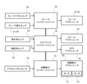
- FIG. 2 is a block diagram showing a control system for braking/driving and steering in the vehicle control system.
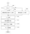
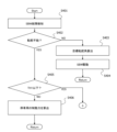
- 4 is a flowchart showing a process of braking moment control.
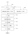
- 4 is a flowchart showing a process of braking moment control.
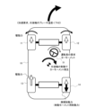
- 11 is a diagram illustrating an example of a braking/driving force distribution when a required acceleration is zero and a frictional braking force is applied to the rear wheels;
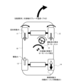
- FIG. 11 is a diagram illustrating an example of braking/driving force distribution when a required acceleration is zero and frictional braking force is applied to the front wheels;
- FIG. 11 is a diagram illustrating an example of braking/driving force distribution when frictional braking force is applied to rear wheels in an acceleration request state.
- FIG. 11 is a diagram illustrating an example of braking/driving force distribution when a frictional braking force is applied to the rear wheels in a state in which deceleration is required.
- FIG. 11 is a diagram illustrating an example of the distribution of braking/driving forces that generates a moment for steering the front wheels.
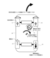
- FIG. 1 is a diagram illustrating a state in which the turning direction requested by the driver differs from the direction of the front wheels;
- 11 is a diagram illustrating an example of the distribution of braking/driving forces when the front wheels are steered in a straight-line travel request state;
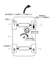
- FIG. 1 is a diagram illustrating a state in which the turning direction requested by the driver differs from the direction of the front wheels;
- 11 is a diagram illustrating an example of the distribution of braking/driving forces when the front wheels
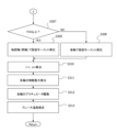
- 5 is a flowchart showing a process of braking moment control including control for returning the front wheels to near a neutral position.
- 5 is a flowchart showing a process of braking moment control including control for returning the front wheels to near a neutral position.
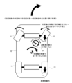
- 11 is a diagram illustrating an example of the distribution of braking/driving forces when returning the front wheels to near the neutral position.
- FIG. 4 is a flowchart showing a process of braking moment control including slip correction control.
- 4 is a flowchart showing a process of braking moment control including slip correction control.
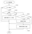
- 4 is a flowchart showing a process of slip correction control.
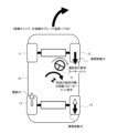
- 6 is a diagram illustrating an example of distribution of braking/driving forces under slip correction control;
- FIG. 1 is an overall configuration diagram showing a vehicle control system 100 mounted on a vehicle 10.
- FIG. 2 is a block diagram that shows a schematic diagram of a control system for braking/driving and steering in the vehicle control system 100.
- FIG. 1 is an overall configuration diagram showing a vehicle control system 100 mounted on a vehicle 10.
- FIG. 2 is a block diagram that shows a schematic diagram of a control system for braking/driving and steering in the vehicle control system 100.
- FIG. 1 is an overall configuration diagram showing a vehicle control system 100 mounted on a vehicle 10.
- FIG. 2 is a block diagram that shows a schematic diagram of a control system for braking/driving and steering in the vehicle control system 100.
- FIG. 1 is an overall configuration diagram showing a vehicle control system 100 mounted on a vehicle 10.
- FIG. 2 is a block diagram that shows a schematic diagram of a control system for braking/driving and steering in the vehicle control system 100.
- the vehicle 10 is a four-wheeled automobile equipped with a pair of left and right front wheels 11, 12 and a pair of left and right rear wheels 13, 14.
- the front wheels 11 and 12 are the first wheels among the wheels 11, 12, 13, and 14 of the vehicle 10, and correspond to the steered wheels.
- the rear wheels 13, 14 are second wheels other than the steered wheels.
- the vehicle 10 also includes, as a braking/driving force actuator 70 , a first electric motor 71 that applies braking/driving forces to the front wheels 11 , 12 , and a second electric motor 72 that applies braking/driving forces to the rear wheels 13 , 14 .
- the braking/driving force control unit 31 obtains information on the amount of operation of the accelerator pedal 73 from the accelerator pedal sensor 74, and outputs a control signal corresponding to a target driving force based on the amount of operation of the accelerator pedal 73 to the electric motors 71, 72, thereby applying a driving force corresponding to the amount of operation of the accelerator pedal 73 to the front wheels 11, 12 and the rear wheels 13, 14.
- the braking/driving force control unit 31 controls regenerative braking in which the rotational resistance generated during power generation is used as a braking force by operating the electric motors 71, 72 as generators, thereby generating regenerative braking force on the front wheels 11, 12 and rear wheels 13, 14.
- the vehicle 10 also includes a steer-by-wire system 40 as a steering device in which a steering wheel 51 and the front wheels 11, 12, which are the steered wheels, are mechanically separated from each other.
- the steer-by-wire system 40 includes a reaction force actuator 41 which applies an operation reaction torque to the steering wheel 51, a wheel actuator 42 which applies a steering force to the front wheels 11, 12, a steering angle sensor 43 which detects the steering angle ⁇ of the front wheels 11, 12 (in other words, the front wheel tire angle), and a steering control unit 32 which controls the reaction force actuator 41 and the wheel actuator 42.
- the steering wheel 51 also includes an operation angle sensor 52 that detects an operation angle ⁇ , which is the rotation angle of the steering wheel 51 .
- the steering angle sensor 43 detects the steering angle ⁇ of the front wheels 11, 12 by detecting the rotation angle of the steering motor that constitutes the wheel actuator 42 and the rack position in the rack and pinion mechanism that converts the rotational force of the steering motor into linear movement.
- the steering control unit 32 acquires information on the operation angle ⁇ of the steering wheel 51 detected by the operation angle sensor 52 (in other words, information on the steering operation), and determines a target steering angle and a target reaction torque from the operation angle ⁇ and the like. Then, the steering control unit 32 controls the wheel actuator 42 so that the steering angle ⁇ detected by the steering angle sensor 43 approaches the target steering angle, and also controls the reaction force actuator 41 so that the target reaction force torque is applied to the steering wheel 51.
- the vehicle 10 also includes a friction braking system that applies friction braking force to each of the wheels 11 , 12 , 13 , and 14 .
- the friction braking system includes a brake control unit 33, a brake pedal sensor 62 which detects the amount of operation of a brake pedal 61, brake actuators 15, 16, 17, 18 provided on each wheel 11, 12, 13, 14, and brake thrust sensors 21, 22, 23, 24 which detect the thrust generated by the brake actuators 15, 16, 17, 18, respectively.
- the brake control unit 33 controls the friction braking forces applied by the brake actuators 15 , 16 , 17 , and 18 to the respective wheels 11 , 12 , 13 , and 14 based on the output of the brake pedal sensor 62 and the outputs of the brake thrust sensors 21 , 22 , 23 , and 24 .
- the brake actuators 15, 16, 17, and 18 are friction braking devices that apply friction braking forces to the wheels 11, 12, 13, and 14, respectively.
- the braking/driving force control unit 31, the steering control unit 32, and the brake control unit 33 each include a microcomputer 31A, 32A, and 33A.
- Each of the microcomputers 31A, 32A, and 33A includes an MPU (Microprocessor Unit), a ROM (Read Only Memory), a RAM (Random Access Memory), etc. (not shown), and realizes various functions by running programs stored in the ROM as a storage unit using the MPU.
- MPU Microprocessor Unit
- ROM Read Only Memory
- RAM Random Access Memory
- the braking/driving force control unit 31 , the steering control unit 32 , and the brake control unit 33 constitute a vehicle control device 30 that controls the vehicle 10 .
- the microcomputers 31A, 32A, and 33A function as a control unit 30A of the vehicle control device 30.
- the vehicle 10 also includes, as sensors for detecting the behavior of the vehicle 10, a yaw rate sensor 81 for detecting a yaw rate ⁇ of the vehicle 10, and a lateral acceleration sensor 82 for detecting a lateral acceleration Gy of the vehicle 10.
- the vehicle 10 also includes a wheel speed sensor 83 that detects the wheel speeds V1, V2, V3, and V4 of the wheels 11, 12, 13, and 14, respectively.
- the control unit 30A (microcomputers 31A, 32A, 33A) acquires output signals from the yaw rate sensor 81, the lateral acceleration sensor 82, and the wheel speed sensor 83 described above.
- the steering control unit 32 (microcomputer 32A) diagnoses whether or not there is an abnormality in the steering function of the steer-by-wire system 40.
- An abnormality in the steering function refers to a state in which the steering angle ⁇ of the front wheels 11, 12, which are the steered wheels, cannot be controlled to a target steering angle corresponding to the operation angle ⁇ of the steering wheel 51 (in other words, the steering operation input to the steer-by-wire system 40).
- Abnormalities in the steering function occur due to factors such as a malfunction of the wheel actuator 42, an abnormality in the drive circuit of the wheel actuator 42, or malfunctions of various sensors.
- the steering control unit 32 When the steering control unit 32 detects an abnormality in the steering function of the steer-by-wire system 40 (in other words, when it obtains an abnormality signal in the steering function), it outputs a braking force command that creates a friction braking force difference between the left and right wheels, thereby generating a yaw moment in the vehicle 10 that corresponds to the operating angle ⁇ of the steering wheel 51, and turns the vehicle 10 in the operating direction of the steering wheel 51.
- the steering control unit 32 changes the direction of the vehicle 10 by controlling the steering angle ⁇ of the front wheels 11, 12, but instead changes the direction of the vehicle 10 by controlling a yaw moment due to the difference in frictional braking force between the left and right wheels (hereinafter referred to as braking moment control).
- FIGS. 3 and 4 are flowcharts showing an example of a procedure for braking moment control (flow of a vehicle control method) executed by the steering control unit 32.
- a system in which the steering control unit 32 executes the braking moment control, a system can be used in which a control unit such as a vehicle integrated control unit that is higher in level than the steering control unit 32 monitors the steering function of the steer-by-wire system 40 and executes braking moment control when an abnormality occurs in the steering function.
- step S201 the steering control unit 32 detects an abnormality in the steering function of the steer-by-wire system 40. Then, in the next step S202, the steering control unit 32 determines whether or not an abnormality has occurred in the steer-by-wire system 40 that disables steering of the front wheels 11, 12.
- the steering control unit 32 proceeds to step S203.
- the steering control unit 32 calculates a target steering angle ⁇ tg of the front wheels 11, 12 based on the operation angle ⁇ of the steering wheel 51 in step S203.
- step S204 the steering control unit 32 controls the wheel actuator 42 to execute normal steering control for bringing the steering angle ⁇ of the front wheels 11, 12 closer to the target steering angle ⁇ tg.
- the steering control unit 32 realizes the turning movement of the vehicle 10 using the steer-by-wire system 40 .
- step S205 the steering control unit 32 determines whether the temperature of a brake actuator (friction braking device) provided on the wheel to be braked, which applies friction braking force by braking moment control, is equal to or lower than a first threshold temperature TH1.
- a brake actuator forriction braking device
- the wheels to be braked to which frictional braking force is applied in order to realize the turning function by braking moment control, are the inner turning wheel of the rear wheels 13, 14 and the inner turning wheel of the front wheels 11, 12.
- the steering control unit 32 determines the turning direction based on the operation angle ⁇ of the steering wheel 51 .
- a force for steering the front wheels 11, 12 in the turning direction can be generated by making the driving force applied to the inner wheel of the front wheels 11, 12 greater than the driving force applied to the outer wheel of the front wheels 11, 12, or by applying a frictional braking force to the outer wheel of the front wheels 11, 12.
- the wheel to be braked, to which frictional braking force is applied in order to realize the turning function by braking moment control, is the outer turning wheel of the front wheels 11, 12.
- the temperature of the brake actuators 15, 16, 17, 18 is, for example, the temperature of the brake rotor.
- the steering control unit 32 estimates the temperature of the brake actuator by estimating the temperature increase due to braking moment control from the initial temperature of the brake actuator, for example from the brake pressure and vehicle speed, and in step S205, compares the estimated temperature with a first threshold temperature TH1.
- the initial temperature can be a set temperature stored in advance in memory, and the steering control unit 32 compares the initial temperature with the first threshold temperature TH1 in step S205 at the beginning of the braking moment control.
- the steering control unit 32 can detect the temperature of each of the brake actuators 15, 16, 17, and 18 from the output of the temperature sensor, and use the detected temperatures for the temperature judgment in steps S205 and S207.
- the first threshold temperature TH1 is a temperature that exceeds the allowable operating temperature of the brake actuators 15, 16, 17, 18 (friction braking devices), and a state in which the temperature of the brake actuator exceeds the first threshold corresponds to a temperature range (in other words, a prohibited temperature range) in which deformation of the brake rotor and a decrease in the frictional braking force against the brake pressure occur.
- the first threshold temperature TH1 is set to, for example, about 350 degrees Celsius.
- step S206 the steering control unit 32 calculates the friction braking force to be generated by the brake actuators 15, 16, 17, and 18 in order to stop the vehicle 10 as a control target, and also performs a setting to stop the application of driving force to all wheels without receiving a driving request from the driver.
- the steering control unit 32 ensures the safety of the vehicle 10 by performing a process (automatic stop process) that prompts the vehicle 10 to stop when the temperature of the brake actuator equipped on the wheel to be braked rises excessively and it becomes impossible to perform braking moment control, in other words, to achieve turning movement by applying frictional braking force.
- the steering control unit 32 determines that braking moment control can be implemented, and proceeds from step S205 to step S207.
- step S207 the steering control unit 32 determines whether the temperature of the brake actuator provided for the turning inner wheel of the rear wheels 13, 14 is equal to or higher than the second threshold temperature TH2.
- the second threshold temperature TH2 is a temperature lower than the first threshold temperature TH1 (TH2 ⁇ TH1), and is a threshold for distinguishing whether or not the temperature condition is such that continued use of the brake actuator is permitted.
- the second threshold temperature TH2 is set to about 200 degrees Celsius.
- step S208 the steering control unit 32 performs an allocation setting in which the target wheel to which frictional braking force (braking force for braking moment) is applied in the braking moment control is the inner turning wheel of the rear wheels 13, 14; in other words, a setting in which a turning moment is generated by the difference in left and right braking force at the rear wheels 13, 14.
- step S209 the steering control unit 32 performs an allocation setting in which the target wheel to which frictional braking force is applied in the braking moment control is the inner wheel (or the outer wheel) of the front wheels 11, 12 for turning; in other words, a setting in which a turning moment is generated by the difference in left and right braking force at the front wheels 11, 12, which are the steered wheels.
- the steering control unit 32 sets the rear wheels 13, 14 as the target wheels for generating a left and right braking force difference as the standard setting, and generates a left and right braking force difference on the rear wheels 13, 14 until the temperature of the brake actuators of the rear wheels 13, 14 becomes equal to or higher than the second threshold temperature TH2. Then, when the application of frictional braking force to the rear wheels 13, 14 continues and the temperature of the brake actuator used to apply the frictional braking force reaches or exceeds a second threshold temperature TH2, the steering control unit 32 switches the target wheels for generating a left and right braking force difference from the rear wheels 13, 14 to the front wheels 11, 12.
- the steering control unit 32 distributes the braking force for the braking moment applied to the front wheels 11, 12 (first wheels) and the rear wheels 13, 14 (second wheels) in accordance with the temperature of the brake actuators 17, 18 (friction braking devices) of the rear wheels 13, 14, which is the state of the vehicle 10. According to this configuration, it is possible to continue the braking moment control for a longer period of time (longer driving distance) while suppressing an excessive increase in temperature of the brake actuator.
- the alignment characteristics (scrub radius) of the front wheels 11, 12 can cause unstable steering, which can reduce the accuracy of yaw moment control.
- the rear wheels 13, 14 which are not steerable wheels, no steering occurs even if a left-right braking force difference is generated, so that a yaw moment corresponding to the left-right braking force difference can be obtained with high accuracy.
- the steering control unit 32 first performs control for generating a left-right braking force difference at the rear wheels 13, 14, which is expected to have high control accuracy. Then, when the temperature of the brake actuators for the rear wheels 13, 14 becomes high, the control shifts to one that generates a left-right braking force difference at the front wheels 11, 12, although the control accuracy of the turning moment decreases. Therefore, it is possible to increase the duration (distance) of the braking moment control while increasing the accuracy of the braking moment control as much as possible.
- step S210 the steering control unit 32 calculates a target yaw rate ⁇ * from the operation angle ⁇ of the steering wheel 51 and the vehicle speed V, and calculates a target acceleration ⁇ * from the operation amount of the accelerator pedal 73 and the operation amount of the brake pedal 61.
- step S211 the steering control unit 32 calculates the target braking/driving forces of the respective wheels 11, 12, 13, 14 based on the target yaw rate ⁇ *, the target acceleration ⁇ *, and further the distribution setting of the friction braking force in the braking moment control. Then, in step S212, the steering control unit 32 outputs a braking force control command to the brake control unit 33 based on the target braking/driving forces of the respective wheels 11, 12, 13, and 14, and outputs a driving force control command to the braking/driving force control unit 31.
- step S213 the steering control unit 32 estimates the temperatures of all of the brake actuators 15, 16, 17, and 18 based on the brake pressure and the vehicle speed.
- the steering control unit 32 compares the estimated temperature obtained in step S213 with the threshold temperature in steps S205 and S207.
- the brake control unit 33 performs a process of estimating the temperatures of the brake actuators 15, 16, 17, and 18, and the steering control unit 32 acquires information on the temperatures estimated by the brake control unit 33 and can use this information for braking moment control.
- the second threshold temperature TH2 used for determining whether to switch the wheels to which the braking force for the braking moment is distributed is set to about 200 degrees Celsius. Therefore, when the steering function of the steer-by-wire system 40 has failed, for example, when the steering wheel 51 is turned to the right, if the temperature of the brake actuator 18 that applies a frictional braking force to the right rear wheel 14 of the rear wheels 13, 14 is 100 degrees Celsius, a frictional braking force will be applied to the right rear wheel 14, and if the temperature of the brake actuator 18 is 300 degrees Celsius, a frictional braking force will be applied to the right front wheel 12 of the front wheels 11, 12.
- FIGS. 5 and 6 show examples of switching of the braking/driving force distribution based on the temperature of the brake actuator in a state where the driver has operated the steering wheel 51 from the neutral position to the right, requesting a right turn of the vehicle 10, and the acceleration/deceleration request by the driver (in other words, the requested acceleration/deceleration required of the vehicle 10) is zero, i.e., in a constant speed driving state.
- the acceleration/deceleration request by the driver is determined from the amount of operation of the accelerator pedal 73 and the amount of operation of the brake pedal 61 .
- FIG. 5 shows the initial distribution state of the braking/driving forces when the steering function of the steer-by-wire system 40 fails and the steering control unit 32 starts the braking moment control.
- the steering control unit 32 distributes braking force (friction braking force) for the braking moment to the right rear wheel 14, which is the inner turning wheel of the rear wheels 13, 14, thereby generating a braking/driving force difference between the left rear wheel 13 and the right rear wheel 14, and generating a turning moment that turns the vehicle 10 to the right.
- a braking force for the braking moment is applied to one of the left and right wheels and no braking force for the braking moment is applied to the other, but a frictional braking force is applied to both the left and right wheels while creating a difference between the frictional braking force applied to one of the left and right wheels and the frictional braking force applied to the other.
- the steering control unit 32 outputs a regenerative braking command to the front wheels 11 and 12 to generate a regenerative braking force. Furthermore, the steering control unit 32 executes drive control to output a drive command to the braking/driving force control unit 31 to generate drive force on the rear wheels 13 , 14 , thereby realizing the running of the vehicle 10 .
- the steering control unit 32 controls so that the sum of the frictional braking force applied to the right rear wheel 14 by braking moment control, the regenerative braking force applied to the front wheels 11, 12 by regenerative braking control, and the driving force applied to the rear wheels 13, 14 by drive control becomes zero.
- the steering control unit 32 adjusts the distribution of braking and driving forces to a state in which the acceleration/deceleration request is zero by making the sum of the friction braking force, regenerative braking force and driving force zero for the entire vehicle.
- Figure 5 shows a state in which there is a difference in the driving forces applied to the left and right rear wheels 13, 14. This indicates that the driving forces applied to the left and right rear wheels 13, 14 are different due to the function of a differential gear that transmits the output of the second electric motor 72 to the left rear wheel 13 and the right rear wheel 14.
- the temperature of the brake actuator 18 which applies a braking force for braking moment to the right rear wheel 14, which is the inner wheel during turning, will rise due to frictional heat. Therefore, when the temperature of the brake actuator 18 becomes equal to or higher than the second threshold temperature TH2, the steering control unit 32 determines that the brake actuator 18 cannot be used continuously, and switches the distribution of the braking/driving forces to the distribution shown in FIG.
- the distribution of driving and braking forces shown in FIG. 6 is a distribution in which the distribution of driving and braking forces shown in FIG.
- the steering control unit 32 distributes braking force for the braking moment to the right front wheel 12, which is the inner turning wheel of the front wheels 11, 12, thereby creating a braking/driving force difference between the left front wheel 11 and the right front wheel 12, and generating a turning moment that turns the vehicle 10 to the right.
- the steering control unit 32 applies a regenerative braking force to the rear wheels 13, 14, and also applies a driving force to the front wheels 11, 12.
- the steering control unit 32 controls so that the sum of the frictional braking force applied to the right front wheel 12 by braking moment control, the regenerative braking force applied to the rear wheels 13, 14 by regenerative braking control, and the driving force applied to the front wheels 11, 12 by drive control becomes zero.
- the steering control unit 32 when the driver operates the steering wheel 51 to the left from the neutral position and requests the vehicle 10 to turn left, the steering control unit 32 first distributes braking force for the braking moment to the left rear wheel 13 to generate a turning moment that turns the vehicle 10 left. Then, when the temperature of the brake actuator 17 that applies a frictional braking force to the left rear wheel 13 becomes equal to or higher than a second threshold temperature TH2, the steering control unit 32 switches to a state in which a turning moment is generated to turn the vehicle 10 to the left by distributing a braking force for the braking moment to the left front wheel 11.
- the steering control unit 32 switches the wheel to which the braking force for the braking moment is distributed from the inner turning wheel of the rear wheels 13, 14 to the inner turning wheel of the front wheels 11, 12 in response to the temperature rise of the brake actuator. According to this braking moment control, it is possible to continuously generate a turning moment in the turning direction requested by the driver while preventing the temperature of the brake actuator from increasing excessively.
- FIG. 7 illustrates an example of the braking/driving force distribution when the driver is requesting that the vehicle 10 turn right and accelerate, and the temperature of the brake actuator 18 for the right rear wheel 14, which is on the inside of the turn, is below the second threshold temperature TH2.
- the steering control unit 32 distributes the braking force for the braking moment to the right rear wheel 14, which is the inner wheel of the turning wheel, of the rear wheels 13, 14.
- the steering control unit 32 also provides driving force to the rear wheels 13, 14 to realize traveling, and provides driving force to the front wheels 11, 12 in response to an acceleration request from the driver.
- the steering control unit 32 switches the braking/driving force distribution between the front wheels 11, 12 and the rear wheels 13, 14.
- FIG. 8 illustrates an example of the braking/driving force distribution when the driver is requesting that the vehicle 10 turn right and decelerate, and the temperature of the brake actuator 18 for the right rear wheel 14, which is on the inside of the turn, is below the second threshold temperature TH2.
- the steering control unit 32 distributes the braking force for the braking moment to the right rear wheel 14, which is the inner wheel of the turning wheel, of the rear wheels 13, 14.
- the steering control unit 32 realizes traveling by generating a driving force to the rear wheels 13, 14, and generates a regenerative braking force to the front wheels 11, 12 in response to a deceleration request.
- the steering control unit 32 switches the braking/driving force distribution between the front wheels 11, 12 and the rear wheels 13, 14.
- the steering control unit 32 when distributing the braking force for the braking moment to the rear wheels 13, 14, the steering control unit 32 satisfies the driver's acceleration/deceleration request by controlling the braking/driving force applied to the front wheels 11, 12. Furthermore, when distributing the braking force for the braking moment to the front wheels 11, 12, the steering control unit 32 satisfies the driver's acceleration/deceleration requirements by controlling the braking/driving forces applied to the rear wheels 13, 14.
- the steering control unit 32 distributes the braking force for the braking moment to the front wheels 11, 12 to generate a left-right braking force difference, and can steer the front wheels 11, 12 in the turning direction requested by the driver by utilizing the alignment characteristics (scrub radius) of the front wheels 11, 12.
- Figure 9 shows a state in which, when the steering wheel 51 is turned to the right, the braking force for the braking moment is distributed to the front wheels 11 and 12 based on the temperature of the brake actuator 18 for the right rear wheel 14, which is the inner wheel of the turning wheel out of the rear wheels 13 and 14, becoming equal to or higher than the second threshold temperature TH2. It should be noted that the scrub radius of the front wheels 11, 12 is assumed to be negative. At this time, the steering control unit 32 distributes the braking force for the braking moment to the left front wheel 11, which is the outer turning wheel of the front wheels 11, 12.
- the moments generated at the front wheels 11, 12 will differ, causing the steering angles of the front wheels 11, 12 to change. For example, when a greater braking force is applied to the left front wheel 11 of the front wheels 11, 12, the front wheels 11, 12 are steered to the right, and when a greater braking force is applied to the right front wheel 12 of the front wheels 11, 12, the front wheels 11, 12 are steered to the left.
- the allocation of the braking force for the braking moment depending on the temperature of the brake actuator is not limited to switching from the inner turning wheel of the rear wheels 13, 14 to the inner turning wheel of the front wheels 11, 12, but can also be switching from the inner turning wheel of the rear wheels 13, 14 to the outer turning wheel of the front wheels 11, 12 when the scrub radius is negative.
- the steering control unit 32 can return the steering angle of the front wheels 11, 12 to near the neutral position by utilizing the fact that the front wheels 11, 12 can be steered in the desired direction by generating a braking force difference between the front wheels 11, 12.
- FIG. 10 shows a case where the steering function of the steer-by-wire system 40 fails and the front wheels 11, 12 are steered to the right side opposite to the right turning direction requested by the driver.
- the steering control unit 32 attempts to turn the vehicle 10 to the right by applying a frictional braking force to the inner turning wheel of the rear wheels 13, 14, the lateral tire force generated by the front wheels 11, 12 acts in a direction that turns the vehicle 10 to the left, thereby reducing the effectiveness of the braking moment control.
- FIG. 11 shows a case where the steering function of the steer-by-wire system 40 fails, and the front wheels 11, 12 are steered to the right despite the driver requesting straight ahead driving.
- the front wheels 11, 12 are steered to the right, in order to make the vehicle 10 go straight, it becomes necessary to apply a braking force to the left rear wheel 13 and generate a turning moment by the braking force difference of the rear wheels 13, 14 to cancel out the turning moment generated by the steering angle of the front wheels 11, 12.
- the steering control unit 32 If the steering control unit 32 generates a braking force difference between the front wheels 11, 12 and returns the steering angle of the front wheels 11, 12 to near the neutral position when the steering function of the steer-by-wire system 40 fails, the turning function through braking moment control can be stably obtained, and the need to continue applying frictional braking force when driving the vehicle 10 in a straight line is reduced.
- FIGS. 12 and 13 show the procedure of braking moment control, which is carried out by the steering control unit 32, including the process of returning the front wheels 11, 12 to near the neutral position.
- 12 are the same processes as steps S201 to S204 in the flowchart of FIG. 3, and steps S307 to S313 in the flowchart of FIG. 13 are the same processes as steps S207 to S213 in the flowchart of FIG.
- steps S301 to S304 and steps S307 to S313 will be omitted, and the processing in steps S305 to S306 will be described in detail below.
- step S302 determines that the steer-by-wire system 40 is unable to steer the front wheels 11, 12, the process proceeds to step S305.
- step S305 the steering control unit 32 determines whether or not the absolute value of the steering angle ⁇ [deg] of the front wheels 11, 12 is equal to or smaller than a predetermined angle ⁇ th.
- the steering angle ⁇ is indicated by zero at the neutral position, and the sign, plus or minus, indicates whether the steering angle is to the right from the neutral position or to the left from the neutral position. Therefore, in step S305, the steering control unit 32 determines whether the front wheels 11, 12 are near the neutral position.
- the steering angle ⁇ that the steering control unit 32 determines in step S305 is a detection value by the steering angle sensor 43 or an estimated value of the steering angle ⁇ .
- the steering control unit 32 can, for example, generate a braking/driving force difference between the rear wheels 13, 14 so as to generate a target yaw rate or a target lateral acceleration, and estimate the steering angle ⁇ of the front wheels 11, 12 based on the difference between the target yaw rate or target lateral acceleration and the actually generated yaw rate or lateral acceleration.
- step S305 the steering control unit 32 determines in step S305 that the absolute value of the steering angle ⁇ exceeds the predetermined angle ⁇ th and the front wheels 11, 12 are steered to the right or left by more than the predetermined amount, the process proceeds to step S306.
- step S306 the steering control unit 32 performs a process for causing the absolute value of the steering angle ⁇ of the front wheels 11, 12 to fall below a predetermined angle ⁇ th, in other words, a process for returning the steering angle ⁇ of the front wheels 11, 12 to near the neutral position, without using the steer-by-wire system 40.
- the predetermined angle ⁇ th in step S305 is a threshold value for distinguishing whether the current steering angle ⁇ is an angle that can be left as is or an angle that requires processing to return it to a smaller angle when braking moment control is performed.
- step S305 if the steering control unit 32 determines in step S305 that the absolute value of the steering angle ⁇ is equal to or smaller than the predetermined angle ⁇ th, in other words, that the steering angle ⁇ is near the neutral position, it proceeds to step S307, bypassing step S306. In other words, if the absolute value of the steering angle ⁇ is equal to or smaller than the predetermined angle ⁇ th, the steering control unit 32 determines that it is not necessary to perform processing to return the steering angle ⁇ of the front wheels 11, 12 to near the neutral position.
- step S306 the steering control unit 32 generates a braking force difference between the front wheels 11, 12 so that the absolute value of the steering angle ⁇ of the front wheels 11, 12 becomes equal to or smaller than a predetermined angle ⁇ th. For example, if the scrub radius of the front wheels 11, 12 is negative and the front wheels 11, 12 are steered to the right from the neutral position, the steering control unit 32, in step S306, applies a frictional braking force to the right front wheel 12 via the brake actuator 16, thereby steering the front wheels 11, 12 back toward the neutral position.
- the steering control unit 32 in step S306, applies a frictional braking force to the left front wheel 11 by the brake actuator 15, thereby steering the front wheels 11, 12 back toward the neutral position.
- the steering control unit 32 proceeds to step S307 and performs braking moment control to switch the wheels that generate a braking force difference between the left and right wheels from the rear wheels 13, 14 to the front wheels 11, 12 in response to the temperature rise of the brake actuator.
- step S306 when the steering control unit 32 performs the process of steering the front wheels 11, 12 back toward the neutral position in step S306, it applies a braking force for braking moment, which is a friction braking force, to the inner turning wheel of the rear wheels 13, 14, thereby generating a turning moment. This prevents a turning moment from being generated during the process of turning the front wheels 11, 12 back toward the neutral position, thereby preventing a delay in the turning operation.
- a braking force for braking moment which is a friction braking force
- FIG. 14 is a state diagram for explaining the control operation of the process of returning the front wheels 11, 12 to near the neutral position.
- FIG. 14 illustrates an example in which the scrub radius of the front wheels 11, 12 is negative, the driver requests a right turn, and the front wheels 11, 12 are steered to the right when the steering function of the steer-by-wire system 40 fails.
- the steering control unit 32 applies a frictional braking force to the right front wheel 12 of the front wheels 11, 12, thereby generating a moment that steers the right front wheel 12 to the left, and by following the steering of the right front wheel 12 to the left, the left front wheel 11 is also steered to the left, thereby steering the front wheels 11, 12 back to near the neutral position.
- the steering control unit 32 generates the rightward turning moment required by the driver by distributing a braking force for the braking moment to the right rear wheel 14, which is the inner turning wheel of the rear wheels 13, 14, in parallel with the steering back of the front wheels 11, 12.
- the steering control unit 32 transitions to normal braking moment control, for example, as shown in FIG.
- the front wheels 11, 12 are turned back to the neutral position before transitioning to the control state shown in Figure 5
- the control accuracy of the turning moment generated by applying a frictional braking force to the right rear wheel 14 is ensured, and turning performance is improved.
- the steering control unit 32 actively returns the front wheels 11, 12 to the neutral position, thereby allowing the vehicle 10 to travel straight without distributing braking force for the braking moment.
- the front wheels 11, 12 are steered, it becomes necessary to generate a turning moment that offsets the turning moment caused by the steering by using a braking/driving force difference between the left and right wheels.
- the front wheels 11, 12 are returned to the neutral position, there is no need to generate a difference in braking/driving force between the left and right wheels, and temperature rise in the brake actuator and uneven wear of the tires can be suppressed.
- FIGS. 15 to 17 are flow charts showing an embodiment of a procedure for braking moment control that can prevent deterioration of cornering performance due to the occurrence of slippage.
- the braking moment control shown in the flowcharts of Figures 15 to 17, as will be described in detail later, is a control that prevents a decrease in cornering performance due to the occurrence of slip by distributing the braking force for the braking moment applied to the front wheels 11, 12 (first wheels) and the rear wheels 13, 14 (second wheels) in accordance with the slip state of the vehicle 10.
- steps S201 to S211 in FIGS. 3 and 4 are the same processes as steps S413 to S414 in FIG. 16 are the same processes as steps S212 to S213 in FIG.
- steps S413 to S414 in FIG. 16 are the same processes as steps S212 to S213 in FIG.
- step S412 the steering control unit 32 executes slip correction control, which is a control for correcting the distribution of braking/driving force when the wheel generating the turning moment slips.
- slip correction control is a control for correcting the distribution of braking/driving force when the wheel generating the turning moment slips.
- the flowchart in FIG. 17 shows the details of the process in step S412.
- step S412A the steering control unit 32 determines whether slip is occurring in one or more wheels (one of the left and right wheels or both left and right wheels) of the front wheels 11, 12 or rear wheels 13, 14 generating a turning moment.
- the steering control unit 32 determines the occurrence of slip when the tire slip ratio obtained from the output of the wheel speed sensor 83 exceeds a threshold value.
- step S413 If slip is not occurring on either the left or right wheel generating the turning moment, the steering control unit 32 proceeds to step S413 without carrying out slip correction control. On the other hand, if slippage is occurring in at least one of the wheels generating the turning moment, the steering control unit 32 proceeds to step S412B. In step S412B, the steering control unit 32 determines whether the wheel on the opposite left or right side to the slipping wheel is also slipping, or whether slipping is occurring in both the left and right wheels.
- step S412C the steering control unit 32 reduces the braking/driving force applied to the slipping wheel so as to ensure the required turning moment while suppressing slippage of the slipping wheel, while increasing the braking/driving force applied to the wheel opposite to the left or right wheel that is paired with the slipping wheel.
- the steering control unit 32 reduces the driving force of the rear wheels 13, 14 and increases the frictional braking force applied to the turning inner wheel that is not slipping. As a result, slippage of the outer wheels during turning is suppressed, and the braking/driving force difference is maintained between the rear wheels 13, 14, thereby ensuring the required turning moment. At this time, the steering control unit 32 adjusts the braking/driving forces applied to the front wheels 11, 12 to achieve the required acceleration/deceleration.
- step S412D the steering control unit 32 determines whether or not the temperature of the brake actuator for the inside turning wheel to which frictional braking force is applied in order to generate a turning moment is equal to or lower than the first threshold temperature TH1.
- step S412F If the temperature of the brake actuator on the inner wheel side of the turn exceeds the first threshold temperature TH1, the steering control unit 32 proceeds to step S412F and, similar to step S206, calculates the frictional braking force to be generated by the brake actuators 15, 16, 17, and 18 to stop the vehicle 10 as a control target. On the other hand, if the temperature of the brake actuator on the inside wheel side is equal to or lower than the first threshold temperature TH1, the steering control unit 32 proceeds to step S412E.
- step S412E the steering control unit 32 corrects the target braking/driving forces (front/rear distribution amounts) of the wheels 11, 12, 13, and 14 determined in step S411 so as to generate the necessary turning moment while suppressing slip. For example, when slippage occurs in the rear wheels 13, 14 while a frictional braking force for braking moment, which is a braking force, is being applied to the inside of the turning rear wheels 13, 14, the steering control unit 32 reduces the braking/driving force applied to the rear wheels 13, 14 in step S412E to prevent the rear wheels 13, 14 from slipping.
- step S412E the steering control unit 32 compensates for the shortage of turning moment caused by weakening the braking/driving force applied to the rear wheels 13, 14 by applying a braking force for the braking moment to the inner one of the front wheels 11, 12.
- FIG. 18 is a diagram showing an overview of the braking/driving force correction (distribution correction) in step S412E, taking as an example a state in which the driver requests a right turn. Because a right turn is required, the steering control unit 32 executes braking moment control to apply a braking force for braking moment, which is a friction braking force, to the right rear wheel 14, which is the inner turning wheel of the rear wheels 13, 14, and also executes drive control to apply a driving force to the rear wheels 13, 14.
- a braking force for braking moment which is a friction braking force
- the steering control unit 32 reduces the braking/driving force applied to the rear wheels 13, 14 through braking moment control and drive control in order to suppress such slippage.
- the steering control unit 32 reduces the braking/driving force applied to the rear wheels 13, 14, the difference in braking/driving force between the rear wheels 13, 14 becomes smaller, so that the turning moment generated at the rear wheels 13, 14 becomes smaller, and the turning moment required by the driver cannot be satisfied.
- the steering control unit 32 generates the turning moment required by the driver by applying a braking force for braking moment, which is a friction braking force, to the right front wheel 12, which is the inner turning wheel of the front wheels 11, 12, in order to compensate for the shortage of turning moment.
- a braking force for braking moment which is a friction braking force
- the slip correction control can prevent the deterioration of turning performance caused by the occurrence of slip, and allows the braking moment control to function stably.
- the steering control unit 32 can switch the distribution to apply friction braking force to the inner turning wheel of the front wheels 11, 12 and the inner turning wheel of the rear wheels 13, 14, as shown in Figure 18.
- the steering control unit 32 can perform control to distribute the braking force for the braking moment applied to the front wheels 11, 12 and the rear wheels 13, 14 in accordance with the slip state of the wheels, without performing control to distribute the braking force for the braking moment applied to the front wheels 11, 12 and the rear wheels 13, 14 in accordance with the temperature of the brake actuator.
- the vehicle control device 30 (steering control unit 32) transitions from a state in which braking force for the braking moment is distributed to the rear wheels 13, 14 to a state in which braking force for the braking moment is distributed to the front wheels 11, 12, which are steered wheels, it can transiently distribute the braking force for the braking moment to both the rear wheels 13, 14 and the front wheels 11, 12.
- the vehicle control device 30 (steering control unit 32) can distribute braking force for the braking moment to both the rear wheels 13, 14 and the front wheels 11, 12 in a ratio that corresponds to the ratio between the temperature of the brake actuator of the inner wheel of the turn among the rear wheels 13, 14 and the temperature of the brake actuator of the inner wheel of the turn (or the previous outer wheel) among the front wheels 11, 12.
- the vehicle 10 may be a work vehicle such as a forklift or construction machine equipped with a steer-by-wire system for steering the rear wheels 13, 14.
- a vehicle 10 equipped with a steer-by-wire system that steers the rear wheels 13, 14 when the temperature of the friction braking device that applies friction braking force to the inner turning wheel of the front wheels 11, 12 is lower than a first threshold temperature TH1, the vehicle control device 30 distributes a braking force for braking moment to the inner turning wheel of the front wheels 11, 12, and when the temperature of the friction braking device that applies friction braking force to the inner turning wheel of the front wheels 11, 12 becomes higher than the first threshold temperature TH1, the vehicle control device 30 distributes the braking force for braking moment to the inner turning wheel of the rear wheels 13, 14, which are the steered wheels.
- the wheels steered by the steer-by-wire system may be either the front wheels 11, 12 or the rear wheels 13, 14.
- vehicle 10 needs to have at least four wheels, namely a pair of left and right wheels (first wheels) that are steered wheels, and a pair of left and right wheels (second wheels) that are not steered wheels, and may be a six-wheel vehicle.
- the vehicle instead of electric motors 71, 72, the vehicle may be equipped with an internal combustion engine as a drive source, or one of the front and rear wheels may be provided with driving force by an internal combustion engine, and the other may be provided with braking and driving force by an electric motor.
- the vehicle control device 30 (steering control unit 32) distributes the braking force for the braking moment applied to the first wheel, which is a steered wheel, and the second wheel other than the steered wheel, in accordance with the temperature of the friction braking device and the slip state of the wheels, which are the conditions of the vehicle, but the conditions of the vehicle are not limited to the temperature of the friction braking device and the slip state of the wheels.
- the vehicle control device 30 can allocate the braking force for the braking moment to be applied to the first wheel, which is a steered wheel, and the second wheel other than the steered wheel, depending on physical quantities that affect the turning moment generated by the difference in braking/driving force between the left and right wheels, such as wheel load, tire air pressure, degree of tire deterioration (amount of wear), and friction coefficient of the road surface.
Landscapes
- Engineering & Computer Science (AREA)
- Transportation (AREA)
- Mechanical Engineering (AREA)
- Chemical & Material Sciences (AREA)
- Combustion & Propulsion (AREA)
- Automation & Control Theory (AREA)
- Microelectronics & Electronic Packaging (AREA)
- Physics & Mathematics (AREA)
- Fluid Mechanics (AREA)
- Human Computer Interaction (AREA)
- Steering Control In Accordance With Driving Conditions (AREA)
Abstract
Description
また、本発明に係る車両制御方法によれば、その1つの態様において、ステアバイワイヤシステムにおける転舵機能が失陥している状態で、ステアリングホイールが右に切られた際、車両の後輪のうち右後輪に摩擦制動力を付与する摩擦制動装置の温度が摂氏100度である場合は、前記右後輪に摩擦制動力を付与し、前記右後輪に摩擦制動力を付与する摩擦制動装置の温度が摂氏300度である場合は、車両の前輪のうち右前輪に摩擦制動力を付与する。
図1は、車両10に搭載される車両制御システム100を示す全体構成図である。
図2は、車両制御システム100のうち、制駆動及び転舵の制御系を概略的に示すブロック図である。
なお、前輪11,12は、車両10の車輪11,12,13,14のうち、転舵輪に該当する第1車輪である。
また、後輪13,14は、転舵輪以外の第2車輪である。
制駆動力コントロールユニット31は、アクセルペダル73の操作量の情報をアクセルペダルセンサ74から取得し、アクセルペダル73の操作量に基づく目標駆動力に応じた制御信号を電動モータ71,72へ出力することで、アクセルペダル73の操作量に応じた駆動力を前輪11,12と後輪13,14とに付与する。
また、制駆動力コントロールユニット31は、電動モータ71,72を発電機として作動させることで、発電時の回転抵抗を制動力として利用する回生制動を制御し、前輪11,12、後輪13,14に回生制動力を発生させる。
ステアバイワイヤシステム40は、ステアリングホイール51に操作反力トルクを付与する反力アクチュエータ41と、前輪11,12に転舵力を付与するホイールアクチュエータ42と、前輪11,12の転舵角δ(換言すれば、前輪タイヤ角)を検出する転舵角センサ43と、反力アクチュエータ41及びホイールアクチュエータ42を制御するステアリングコントロールユニット32と、を有する。
なお、転舵角センサ43は、ホイールアクチュエータ42を構成する転舵モータの回転角や、転舵モータの回転力を直線の動きに変換するラックアンドピニオン機構におけるラック位置を検出することで、前輪11,12の転舵角δを検出する。
そして、ステアリングコントロールユニット32は、転舵角センサ43が検出する転舵角δが目標転舵角に近づくようにホイールアクチュエータ42を制御し、また、ステアリングホイール51に目標反力トルクが付与されるように、反力アクチュエータ41を制御する。
摩擦制動システムは、ブレーキコントロールユニット33、ブレーキペダル61の操作量を検出するブレーキペダルセンサ62、各車輪11,12,13,14に設けられたブレーキアクチュエータ15,16,17,18、ブレーキアクチュエータ15,16,17,18が発生している推力をそれぞれに検出するブレーキ推力センサ21,22,23,24を有する。
なお、ブレーキアクチュエータ15,16,17,18は、各車輪11,12,13,14に摩擦制動力を付与する摩擦制動装置である。
マイクロコンピュータ31A,32A,33Aは、それぞれ、図示を省略したMPU(Microprocessor Unit)、ROM(Read Only Memory)、RAM(Random Access Memory)などを備え、記憶部としてのROMに記憶されているプログラムをMPUで動作させることにより各種の機能を実現する。
また、マイクロコンピュータ31A,32A,33Aは、車両制御装置30のコントロール部30Aとして機能する。
また、車両10は、各車輪11,12,13,14の車輪速V1,V2,V3,V4をそれぞれに検出する車輪速センサ83を備える。
コントロール部30A(マイクロコンピュータ31A,32A,33A)は、上記のヨーレートセンサ81、横加速度センサ82、及び車輪速センサ83の出力信号を取得する。
なお、転舵機能の異常とは、転舵輪である前輪11,12の転舵角δを、ステアリングホイール51の操作角θ(換言すれば、ステアバイワイヤシステム40に入力されるステアリング操作)に応じた目標転舵角に制御することができなくなっている状態である。
転舵機能の異常は、ホイールアクチュエータ42の故障、ホイールアクチュエータ42の駆動回路の異常、各種センサの故障などを要因として生じる。
つまり、ステアリングコントロールユニット32は、ステアバイワイヤシステム40の転舵機能に異常が生じると、前輪11,12の転舵角δの制御によって車両10の向きを変える代わりに、左右輪の間での摩擦制動力差によりヨーモーメントを発生させる制御(以下、制動モーメント制御と称する。)によって車両10の向きを変える。
なお、ステアリングコントロールユニット32が制動モーメント制御を実行するシステムに代えて、ステアリングコントロールユニット32よりも上位の車両統合コントロールユニットなどのコントロールユニットが、ステアバイワイヤシステム40の転舵機能を監視し、転舵機能に異常が発生したときに制動モーメント制御を実行するシステムとすることができる。
そして、ステアリングコントロールユニット32は、次のステップS202で、ステアバイワイヤシステム40に、前輪11,12の転舵が不能である異常が発生しているか否かを判断する。
ステアリングコントロールユニット32は、ステップS203で、ステアリングホイール51の操作角θに基づき、前輪11,12の目標転舵角δtgを算出する。
つまり、ステアリングコントロールユニット32は、ステアバイワイヤシステム40が正常である場合は、ステアバイワイヤシステム40を用いて車両10の旋回運動を実現する。
ステアリングコントロールユニット32は、ステップS205で、制動モーメント制御によって摩擦制動力を付与する制動対象輪が備えるブレーキアクチュエータ(摩擦制動装置)の温度が、第1閾値温度TH1以下であるか否かを判断する。
ステアリングコントロールユニット32は、旋回方向を、ステアリングホイール51の操作角θに基づき判断する。
この場合、制動モーメント制御によって旋回機能を実現するために摩擦制動力を付与する制動対象輪は、前輪11,12のうちの旋回外輪になる。
後述するように、ステアリングコントロールユニット32は、ブレーキアクチュエータの初期温度からの制動モーメント制御による温度上昇分を、たとえばブレーキ圧と車速から推定することでブレーキアクチュエータの温度を推定し、ステップS205で、推定温度と第1閾値温度TH1とを比較する。
なお、車両10がブレーキアクチュエータ15,16,17,18それぞれの温度を検出する温度センサを備える場合、ステアリングコントロールユニット32は、温度センサの出力からブレーキアクチュエータ15,16,17,18それぞれの温度を検出し、検出した温度を、ステップS205やステップS207の温度判定に用いることができる。
第1閾値温度TH1は、たとえば、摂氏350度程度に設定される。
ステアリングコントロールユニット32は、ステップS206で、車両10を停止させるためにブレーキアクチュエータ15,16,17,18で発生させる摩擦制動力を制御目標として算出し、かつ、運転者による駆動要求を受けずに全輪への駆動力の付与を停止する設定を実施する。
このように、ステアリングコントロールユニット32は、制動対象輪が備えるブレーキアクチュエータの温度が過度に上昇して、制動モーメント制御の実施、換言すれば、摩擦制動力の付与による旋回運動の実現が不能になったときに、車両10の停止を促す処理(自動停止処理)を実施することで、車両10の安全を確保する。
ステアリングコントロールユニット32は、ステップS207で、後輪13,14のうちの旋回内輪が備えるブレーキアクチュエータの温度が第2閾値温度TH2以上であるか否かを判断する。
第2閾値温度TH2は、第1閾値温度TH1よりも低い温度であって(TH2<TH1)、ブレーキアクチュエータの継続使用が許容される温度条件であるか否かを区別するための閾値である。
たとえば、第2閾値温度TH2は、摂氏200度程度に設定される。
そして、ステアリングコントロールユニット32は、ステップS208で、制動モーメント制御において摩擦制動力(制動モーメント用制動力)を付与する対象輪を、後輪13,14のうちの旋回内輪とする配分設定、換言すれば、後輪13,14での左右制動力差によって旋回モーメントを発生させる設定を実施する。
そして、ステアリングコントロールユニット32は、ステップS209で、制動モーメント制御において摩擦制動力を付与する対象輪を、前輪11,12のうちの旋回内輪(若しくは旋回外輪)とする配分設定、換言すれば、転舵輪である前輪11,12での左右制動力差によって旋回モーメントを発生させる設定を実施する。
そして、ステアリングコントロールユニット32は、後輪13,14への摩擦制動力の付与が継続されることで、摩擦制動力の付与に供されるブレーキアクチュエータの温度が第2閾値温度TH2以上になると、左右制動力差を発生させる対象輪を、後輪13,14から前輪11,12に切り替える。
係る構成によれば、ブレーキアクチュエータの過度な温度上昇を抑制しつつ、より長い時間(より長い走行距離)にわたって制動モーメント制御を継続することができる。
これに対し、転舵輪ではない後輪13,14においては、左右制動力差を発生させても転舵が生じないので、左右制動力差に応じたヨーモーメントを高い精度で得ることが可能である。
そして、後輪13,14のブレーキアクチュエータの温度が高くなると、旋回モーメントの制御精度としては低下するものの、前輪11,12で左右制動力差を発生させる制御に移行する。
したがって、制動モーメント制御の継続時間(継続距離)を拡大しつつ、制動モーメント制御の精度を可及的に高くすることができる。
ステアリングコントロールユニット32は、ステップS210で、ステアリングホイール51の操作角θ、車速Vから目標ヨーレートγ*を算出し、アクセルペダル73の操作量、ブレーキペダル61の操作量から目標加速度α*を算出する。
そして、ステアリングコントロールユニット32は、ステップS212で、各車輪11,12,13,14の目標制駆動力に基づいてブレーキコントロールユニット33に制動力制御指令を出力し、制駆動力コントロールユニット31に駆動力制御指令を出力する。
ステアリングコントロールユニット32は、ステップS213で求めた推定温度と閾値温度とを、ステップS205及びステップS207で比較する。
なお、ブレーキコントロールユニット33が、ブレーキアクチュエータ15,16,17,18の温度を推定する処理を実施し、ステアリングコントロールユニット32は、ブレーキコントロールユニット33が推定した温度の情報を取得して、制動モーメント制御に用いることができる。
したがって、ステアバイワイヤシステム40における転舵機能が失陥している状態で、たとえば、ステアリングホイール51が右に切られた際、後輪13,14のうち右後輪14に摩擦制動力を付与するブレーキアクチュエータ18の温度が摂氏100度である場合は右後輪14に摩擦制動力が付与され、ブレーキアクチュエータ18の温度が摂氏300度である場合は前輪11,12のうち右前輪12に摩擦制動力が付与されることになる。
図5及び図6は、運転者がステアリングホイール51を中立位置から右側に操作し、車両10の右旋回を要求している状態であって、かつ、運転者による加減速度要求(換言すれば、車両10に要求される要求加減速度)がゼロの状態、つまり、定速走行状態での、ブレーキアクチュエータの温度による制駆動力配分の切り替えを例示する。
なお、運転者による加減速度要求は、アクセルペダル73の操作量、及び、ブレーキペダル61の操作量から判断される。
ステアリングコントロールユニット32は、制動モーメント制御として、後輪13,14のうちの旋回内輪である右後輪14に制動モーメント用制動力(摩擦制動力)を配分することで、左後輪13と右後輪14との間に制駆動力差を生じさせて、車両10を右旋回させる旋回モーメントを発生させる。
なお、図5に示した制動モーメント用制動力の配分は、左右輪の一方に制動モーメント用制動力を付与し、他方に制動モーメント用制動力を付与しないが、左右両輪に摩擦制動力を付与しつつ、左右輪の一方に付与する摩擦制動力と他方に付与する摩擦制動力との間に差を生じさせる配分であってもよい。
さらに、ステアリングコントロールユニット32は、後輪13,14に駆動力を発生させる駆動指令を制駆動力コントロールユニット31に出力する駆動制御を実行することで、車両10の走行を実現する。
ステアリングコントロールユニット32は、上記のように、摩擦制動力、回生制動力及び駆動力の合計を車両全体でゼロとすることで、制駆動力の配分を、加減速度要求がゼロの状態に適合させる。
なお、図5は、左右の後輪13,14に付与される駆動力に差が生じている状態を示しているが、これは、第2電動モータ72の出力を左後輪13と右後輪14とに伝達するデファレンシャルギア(Differential gear)の機能によって、左右の後輪13,14の駆動力が相違することを示している。
また、図5の右後輪14に制動モーメント用制動力を配分する状態では、転舵輪である前輪11,12には同じ値の回生制動力が付与され、前輪11,12の間では制駆動力差が生じない。
このため、前輪11,12の間での制駆動力差による前輪11,12の転舵が発生せず、右後輪14に付与する摩擦制動力の調整によって、車両10を旋回させるための旋回モーメントを高い精度で制御できる。
そこで、ステアリングコントロールユニット32は、ブレーキアクチュエータ18の温度が第2閾値温度TH2以上になると、ブレーキアクチュエータ18の継続使用が不可の状況であると判断し、制駆動力の配分を図6に示す配分に切り替える。
つまり、ステアリングコントロールユニット32は、制動モーメント制御として、前輪11,12のうちの旋回内輪である右前輪12に制動モーメント用制動力を配分することで、左前輪11と右前輪12との間に制駆動力差を生じさせて、車両10を右旋回させる旋回モーメントを発生させる。
ここで、ステアリングコントロールユニット32は、駆動力を正の物理量、制動力を負の物理量としたとき、制動モーメント制御によって右前輪12に付与する摩擦制動力、回生制動制御によって後輪13,14に付与する回生制動力、及び、駆動制御によって前輪11,12に付与する駆動力の合計値がゼロになるように制御する。
そして、ステアリングコントロールユニット32は、左後輪13に摩擦制動力を付与するブレーキアクチュエータ17の温度が第2閾値温度TH2以上になると、左前輪11に制動モーメント用制動力を配分することで車両10を左旋回させる旋回モーメントを発生させる状態に切り替える。
係る制動モーメント制御によれば、ブレーキアクチュエータの温度が過度に上昇することを抑止しつつ、運転者が要求する旋回方向の旋回モーメントを継続して発生させることができる。
ここで、ステアリングコントロールユニット32は、後輪13,14のうちの旋回内輪である右後輪14に制動モーメント用制動力を配分する。
なお、図7に示す制駆動力の配分状態で、右後輪14に摩擦制動力を付与するブレーキアクチュエータ18の温度が第2閾値温度TH2以上になると、ステアリングコントロールユニット32は、制駆動力配分を前輪11,12と後輪13,14とで入れ替える。
ここで、ステアリングコントロールユニット32は、後輪13,14のうちの旋回内輪である右後輪14に制動モーメント用制動力を配分する。
また、ステアリングコントロールユニット32は、後輪13,14に駆動力を発生させることで走行を実現し、減速要求に応じて前輪11,12に回生制動力を発生させる。
なお、図8に示す制駆動力の配分状態で、右後輪14に摩擦制動力を付与するブレーキアクチュエータ18の温度が第2閾値温度TH2以上になると、ステアリングコントロールユニット32は、制駆動力配分を前輪11,12と後輪13,14とで入れ替える。
また、ステアリングコントロールユニット32は、制動モーメント用制動力を前輪11,12に配分するとき、後輪13,14に与える制駆動力の制御によって運転者の加減速度要求を満たす。
したがって、ステアバイワイヤシステム40の転舵機能に異常が発生したときに、車両10の進行方向をたとえば路肩に向かう方向に変更する機能に加え、運転者の要求に応じた加減速を実現して、運転者が意図する停車位置にまで車両10をたどり着かせるリンプホーム(limp home)が可能となる。
なお、前輪11,12のスクラブ半径は、ネガティブであるものとする。
このとき、ステアリングコントロールユニット32は、前輪11,12のうちの旋回外輪である左前輪11に、制動モーメント用制動力を配分する。
ここで、前輪11,12の転舵機構が、前輪11,12をタイロッドで連結し、前輪11,12を一体として転舵角が変更される機構の場合、前輪11,12の双方に同じ制動力が付与されると、前輪11,12それぞれで発生するモーメントが打ち消し合って、前輪11,12の転舵角は変化しない。
たとえば、前輪11,12のうちの左前輪11により大きな制動力を付与すると、前輪11,12は右方向に転舵され、前輪11,12のうちの右前輪12により大きな制動力を付与すると、前輪11,12は左方向に転舵される。
このように、ブレーキアクチュエータの温度に応じた制動モーメント用制動力の配分切り替えは、後輪13,14のうちの旋回内輪から前輪11,12のうちの旋回内輪への切り替えに限定されず、スクラブ半径がネガティブの場合、後輪13,14のうちの旋回内輪から前輪11,12のうちの旋回外輪への切り替えとすることができる。
係る状態では、ステアリングコントロールユニット32が、後輪13,14のうちの旋回内輪に摩擦制動力を付与ことで、車両10を右旋回させようとしても、前輪11,12が発生するタイヤ横力は車両10を左旋回させる方向に働くので、制動モーメント制御の効果が低下する。
この場合、前輪11,12が右側に転舵されているため、車両10を直進させるためには、左後輪13に制動力を付与して、前輪11,12の転舵角によって発生する旋回モーメントを打ち消す旋回モーメントを後輪13,14の制動力差で発生させる必要が生じる。
そして、摩擦制動力をかけ続けると、ブレーキアクチュエータの温度が上昇し、また、タイヤの偏摩耗が起こる可能性がある。
なお、図12のフローチャートのステップS301-ステップS304は、図3のフローチャートのステップS201-ステップS204と同じ処理であり、また、図13のフローチャートのステップS307-ステップS313は、図4のフローチャートのステップS207-ステップS213と同じ処理である。
このため、ステップS301-ステップS304及びステップS307-ステップS313での処理内容の説明を省略し、ステップS305-ステップS306での処理を、以下で詳細に説明する。
ステアリングコントロールユニット32は、ステップS305で、前輪11,12の転舵角δ[deg]の絶対値が、所定角δth以下であるか否かを判断する。
したがって、ステアリングコントロールユニット32は、ステップS305で、前輪11,12が中立位置付近であるか否かを判断することになる。
ここで、ステアリングコントロールユニット32は、たとえば、目標ヨーレートまたは目標横加速度を発生させるように後輪13,14の間で制駆動力差を生じさせ、目標ヨーレートまたは目標横加速度と、実際に発生したヨーレートまたは横加速度との差に基づいて、前輪11,12の転舵角δを推定することができる。
ステアリングコントロールユニット32は、ステップS306で、ステアバイワイヤシステム40を用いずに、前輪11,12の転舵角δの絶対値が所定角δthを下回るようにする処理、換言すれば、前輪11,12の転舵角δを中立位置付近に戻す処理を実施する。
つまり、ステップS305における所定角δthは、制動モーメント制御の実施する際に、現状の転舵角δが、そのまま放置することができる角度であるか、より小さい角度に戻す処理の実施が要求される角度であるかを区別するための閾値である。
つまり、ステアリングコントロールユニット32は、転舵角δの絶対値が所定角δth以下であれば、前輪11,12の転舵角δを中立位置付近に戻す処理は不要であると判断する。
たとえば、前輪11,12のスクラブ半径がネガティブであって、かつ、前輪11,12が中立位置から右に転舵されている場合、ステアリングコントロールユニット32は、ステップS306で、ブレーキアクチュエータ16によって右前輪12に摩擦制動力を付与することで、前輪11,12を中立位置に向けて切り戻すようにする。
ステアリングコントロールユニット32は、上記のようにして、前輪11,12を中立位置に戻すと、ステップS307以降に進み、ブレーキアクチュエータの温度上昇に応じて、左右輪で制動力差を発生させる車輪を後輪13,14から前輪11,12に切り替える、制動モーメント制御を実施する。
これによって、前輪11,12を中立位置に向けて切り戻す処理の間において、旋回モーメントを発生させることができずに、旋回動作が遅れることが抑止される。
なお、図14は、前輪11,12のスクラブ半径がネガティブで、かつ、運転者が右旋回を要求する場合であって、ステアバイワイヤシステム40の転舵機能が失陥したときに、前輪11,12が右に転舵されていた場合を例示する。
また、ステアリングコントロールユニット32は、前輪11,12の切り戻しに並行して、後輪13,14のうちの旋回内輪である右後輪14に制動モーメント用制動力を配分することで、運転者が要求する右方向の旋回モーメントを発生させる。
ここで、図5に示した制御状態に遷移する前に、前輪11,12が中立位置に切り戻されているので、右後輪14に摩擦制動力を付与することで発生させる旋回モーメントの制御精度が確保され、旋回性能が向上する。
つまり、前輪11,12が転舵されている状態で車両10を直進させるためには、転舵による旋回モーメントを相殺する旋回モーメントを、左右輪の制駆動力差で発生させる必要が生じる。
これに対し、前輪11,12を中立位置に戻しておけば、左右輪の制駆動力差で発生させる必要がなく、ブレーキアクチュエータの温度上昇やタイヤの偏摩耗を抑止できる。
係る車輪のスリップによる旋回性能の低下を抑止できる制動モーメント制御の一態様を以下で説明する。
図15-図17のフローチャートに示す制動モーメント制御は、後で詳細に説明するように、前輪11,12(第1車輪)と後輪13,14(第2車輪)に与える制動モーメント用制動力を、車両10の状態としてのスリップ状態に応じて配分することで、スリップ発生による旋回性能の低下を抑止する制御である。
このため、図15、図16のフローチャートにおいて、ステップS412以外の各ステップについては詳細な説明を省略し、ステップS412での処理を詳細に説明する。
図17のフローチャートは、ステップS412での処理内容を詳細に示す。
ここで、ステアリングコントロールユニット32は、車輪速センサ83の出力から求められたタイヤスリップ率が閾値を超えたときに、スリップの発生を判断する。
一方、ステアリングコントロールユニット32は、旋回モーメントを発生させている車輪のうちの少なくとも1輪でスリップが発生している場合、ステップS412Bに進む。
ステアリングコントロールユニット32は、ステップS412Bで、スリップが発生している車輪と対をなす左右逆の車輪がスリップしていないか、それとも、左右両方の車輪でスリップが発生しているかを判断する。
ステアリングコントロールユニット32は、ステップS412Cで、スリップしている車輪のスリップを抑制しつつ要求の旋回モーメントを確保できるように、スリップしている車輪に付与する制駆動力を低下させる一方で、スリップが発生している車輪と対をなす左右逆の車輪に付与する制駆動力を高める。
これにより、旋回外輪のスリップが抑制され、かつ、後輪13,14の間で制駆動力差が維持されて要求の旋回モーメントが確保される。
このとき、ステアリングコントロールユニット32は、前輪11,12に付与する制駆動力を調整して、要求の加減速度を実現する。
ステアリングコントロールユニット32は、ステップS412Dで、旋回モーメントを発生させるために摩擦制動力を付与している旋回内輪において、ブレーキアクチュエータの温度が第1閾値温度TH1以下であるか否かを判断する。
一方、ステアリングコントロールユニット32は、旋回内輪側のブレーキアクチュエータの温度が第1閾値温度TH1以下である場合、ステップS412Eに進む。
たとえば、ステアリングコントロールユニット32は、後輪13,14のうちの旋回内側に摩擦制動力である制動モーメント用制動力を付与している状態で後輪13,14にスリップが発生すると、ステップS412Eで、後輪13,14に付与する制駆動力を弱め、後輪13,14のスリップを抑止する。
さらに、ステアリングコントロールユニット32は、ステップS412Eで、後輪13,14に付与する制駆動力を弱めたことによる旋回モーメントの不足分を、前輪11,12のうちの旋回内輪に制動モーメント用制動力を付与することで補填する。
右旋回が要求されるため、ステアリングコントロールユニット32は、後輪13,14のうちの旋回内輪である右後輪14に摩擦制動力である制動モーメント用制動力を付与する制動モーメント制御を実行し、また、後輪13,14に駆動力を付与する駆動制御を実行する。
ステアリングコントロールユニット32が後輪13,14に付与する制駆動力を低下させると、後輪13,14の間での制駆動力差が小さくなることで、後輪13,14で発生する旋回モーメントが小さくなり、運転者が要求する旋回モーメントを満たすことができなくなる。
このように、スリップ補正制御によれば、スリップの発生によって旋回性能が低下することを抑止でき、制動モーメント制御を安定的に機能させることができる。
また、ステアリングコントロールユニット32は、前輪11,12と後輪13,14に与える制動モーメント用制動力をブレーキアクチュエータの温度に応じて配分する制御を実施せずに、前輪11,12と後輪13,14に与える制動モーメント用制動力を車輪のスリップ状態に応じて配分する制御を実施することができる。
また、好ましい実施形態を参照して本発明の内容を具体的に説明したが、本発明の基本的技術思想及び教示に基づいて、当業者であれば、種々の変形態様を採り得ることは自明である。
また、車両制御装置30(ステアリングコントロールユニット32)は、後輪13,14のうちの旋回内輪のブレーキアクチュエータの温度と、前輪11,12のうちの旋回内輪(若しくは前回外輪)のブレーキアクチュエータの温度との比率に応じた比率で、後輪13,14と前輪11,12との双方に制動モーメント用制動力を配分することができる。
後輪13,14を転舵するステアバイワイヤシステムを備えた車両10の場合、車両制御装置30は、前輪11,12のうちの旋回内輪に摩擦制動力を付与する摩擦制動装置の温度が第1閾値温度TH1より低い場合は、前輪11,12の旋回内輪に制動モーメント用制動力を配分し、前輪11,12のうちの旋回内輪に摩擦制動力を付与する摩擦制動装置の温度が第1閾値温度TH1より高くなると、転舵輪である後輪13,14のうちの旋回内輪に制動モーメント用制動力を配分する。
つまり、ステアバイワイヤシステムが転舵する転舵輪は、前輪11,12と後輪13,14とのいずれであってもよい。
また、電動モータ71,72に代えて、駆動源として内燃機関を備えた車両、或いは、前輪と後輪とのいずれか一方が内燃機関によって駆動力が与えられ、他方が電動モータによって制駆動力が与えられる車両であってもよい。
たとえば、車両制御装置30(ステアリングコントロールユニット32)は、輪荷重、タイヤ空気圧、タイヤ劣化度合い(摩耗量)、路面の摩擦係数などの左右輪間での制駆動力差で発生する旋回モーメントに影響する物理量に応じて、転舵輪である第1車輪と転舵輪以外の第2車輪に与える制動モーメント用制動力を配分することができる。
Claims (11)
- 車両の車輪のうちの転舵輪を第1車輪、前記車輪のうちの転舵輪以外を第2車輪としたとき、ステアリングホイールと機械的に切り離された前記第1車輪を転舵させるステアバイワイヤシステムと、前記車輪に摩擦制動力を付与する摩擦制動装置と、を有する前記車両に備えられた車両制御装置であって、
前記車両制御装置が備えるコントロール部は、
前記ステアバイワイヤシステムにおける転舵機能の異常信号を取得した際、
前記ステアリングホイールに入力されるステアリング操作に応じて、前記車輪に与える摩擦制動力によって前記車両にヨーモーメントを発生させる制動モーメント制御を実行し、
前記制動モーメント制御において、前記第1車輪と前記第2車輪に与える制動モーメント用制動力を前記車両の状態に応じて配分する、
車両制御装置。 - 請求項1に記載の車両制御装置であって、
前記コントロール部は、
前記制動モーメント用制動力を、前記車両の状態のうち、前記第2車輪の旋回内輪に摩擦制動力を付与する前記摩擦制動装置の温度に基づいて、前記第1車輪の旋回内輪または前記第2車輪の旋回内輪、のうちいずれか一方に配分する、
車両制御装置。 - 請求項2に記載の車両制御装置であって、
前記車両は、前記第1車輪に制駆動力を与える第1電動モータと、前記第2車輪に制駆動力を与える第2電動モータと、を有しており、
前記コントロール部は、
前記制動モーメント用制動力を前記第1車輪に配分するときは、前記第2車輪に回生制動力を発生させる回生制動制御を実行し、
前記制動モーメント用制動力を前記第2車輪に配分するときは、前記第1車輪に回生制動力を発生させる回生制動制御を実行する、
車両制御装置。 - 請求項3に記載の車両制御装置であって、
前記コントロール部は、
前記車両に要求される要求加減速度がゼロである場合、
前記制動モーメント用制動力を前記第1車輪に配分するときは、前記第1車輪に駆動力を発生させる駆動制御を実行し、
前記制動モーメント用制動力を前記第2車輪に配分するときは、前記第2車輪に駆動力を発生させる駆動制御を実行し、
駆動力を正の物理量、制動力を負の物理量としたとき、前記制動モーメント制御による摩擦制動力、前記回生制動制御による回生制動力、及び前記駆動制御による駆動力の合計値がゼロになるように制御する、
車両制御装置。 - 請求項2に記載の車両制御装置であって、
前記コントロール部は、
前記第2車輪の旋回内輪に摩擦制動力を付与する前記摩擦制動装置の温度が第2閾値温度より低い場合は、前記第2車輪の旋回内輪に前記制動モーメント用制動力を配分する、
車両制御装置。 - 請求項5に記載の車両制御装置であって、
前記コントロール部は、
前記第2車輪の旋回内輪に摩擦制動力を付与する前記摩擦制動装置の温度が前記第2閾値温度より高い第1閾値温度を超える場合は、前記車輪に所定の制動力を付与する、
車両制御装置。 - 請求項2に記載の車両制御装置であって、
前記第1車輪は前記車両の前輪、前記第2車輪は前記車両の後輪である、
車両制御装置。 - 請求項1に記載の車両制御装置であって、
前記コントロール部は、
前記制動モーメント用制動力を、前記車両の状態のうち、前記第2車輪のスリップ状態を基づいて、前記第1車輪の旋回内輪と前記第2車輪の旋回内輪に配分する、
車両制御装置。 - 請求項1に記載の車両制御装置であって、
前記第1車輪のスクラブ半径がネガティブに設定されており、
前記コントロール部は、
前記制動モーメント用制動力を、前記車両の状態に応じて前記第1車輪に配分するにあたり、前記第1車輪の旋回外輪に配分する、
車両制御装置。 - 請求項1に記載の車両制御装置であって、
前記コントロール部は、
前記ステアバイワイヤシステムにおける転舵機能の異常信号を取得した際、前記第1車輪の転舵角が所定角を上回る状態である場合、
前記第1車輪の転舵角が前記所定角を下回るように、前記摩擦制動装置によって前記第1車輪に摩擦制動力を与える、
車両制御装置。 - ステアリングホイールと機械的に切り離された、車両の転舵輪である前輪を転舵させるステアバイワイヤシステムと、前記車両の車輪に摩擦制動力を付与する摩擦制動装置と、を有する前記車両に搭載されたコントロール部が実行する車両制御方法であって、
前記ステアバイワイヤシステムにおける転舵機能が失陥している状態で、前記ステアリングホイールが右に切られた際、
前記車両の後輪のうち右後輪に摩擦制動力を付与する摩擦制動装置の温度が摂氏100度である場合は、前記右後輪に摩擦制動力を付与し、
前記右後輪に摩擦制動力を付与する摩擦制動装置の温度が摂氏300度である場合は、前記前輪のうち右前輪に摩擦制動力を付与する、
車両制御方法。
Priority Applications (3)
| Application Number | Priority Date | Filing Date | Title |
|---|---|---|---|
| JP2025531440A JPWO2025009327A1 (ja) | 2023-07-03 | 2024-06-07 | |
| CN202480040106.6A CN121358642A (zh) | 2023-07-03 | 2024-06-07 | 车辆控制装置及车辆控制方法 |
| DE112024002828.4T DE112024002828T5 (de) | 2023-07-03 | 2024-06-07 | Fahrzeugsteuerungseinrichtung und Fahrzeugsteuerungsverfahren |
Applications Claiming Priority (2)
| Application Number | Priority Date | Filing Date | Title |
|---|---|---|---|
| JP2023109147 | 2023-07-03 | ||
| JP2023-109147 | 2023-07-03 |
Publications (1)
| Publication Number | Publication Date |
|---|---|
| WO2025009327A1 true WO2025009327A1 (ja) | 2025-01-09 |
Family
ID=94171662
Family Applications (1)
| Application Number | Title | Priority Date | Filing Date |
|---|---|---|---|
| PCT/JP2024/020820 Ceased WO2025009327A1 (ja) | 2023-07-03 | 2024-06-07 | 車両制御装置、及び、車両制御方法 |
Country Status (4)
| Country | Link |
|---|---|
| JP (1) | JPWO2025009327A1 (ja) |
| CN (1) | CN121358642A (ja) |
| DE (1) | DE112024002828T5 (ja) |
| WO (1) | WO2025009327A1 (ja) |
Citations (7)
| Publication number | Priority date | Publication date | Assignee | Title |
|---|---|---|---|---|
| JPH04287754A (ja) * | 1991-03-18 | 1992-10-13 | Toyota Motor Corp | 制動力制御装置 |
| JP2008044546A (ja) * | 2006-08-18 | 2008-02-28 | Nissan Motor Co Ltd | 車線逸脱防止装置 |
| JP2008179272A (ja) * | 2007-01-25 | 2008-08-07 | Toyota Motor Corp | 摩擦係合部の温度に基づいて前後輪間摩擦制動力配分を変更する車輌 |
| JP2009220617A (ja) * | 2008-03-13 | 2009-10-01 | Toyota Motor Corp | 操舵装置 |
| US20120283907A1 (en) * | 2011-05-05 | 2012-11-08 | GM Global Technology Operations LLC | Lane centering fail-safe control using differential braking |
| EP3090907A1 (en) * | 2015-05-05 | 2016-11-09 | Volvo Car Corporation | Secondary steering system unit, secondary steering system, vehicle and a method for secondary steering |
| US20210086737A1 (en) * | 2019-09-19 | 2021-03-25 | Continental Automotive Systems, Inc. | Vehicle wheel steer control system and method |
Family Cites Families (1)
| Publication number | Priority date | Publication date | Assignee | Title |
|---|---|---|---|---|
| JP3564696B2 (ja) | 1998-12-25 | 2004-09-15 | トヨタ自動車株式会社 | 車両の操舵制御装置 |
-
2024
- 2024-06-07 JP JP2025531440A patent/JPWO2025009327A1/ja active Pending
- 2024-06-07 WO PCT/JP2024/020820 patent/WO2025009327A1/ja not_active Ceased
- 2024-06-07 DE DE112024002828.4T patent/DE112024002828T5/de active Pending
- 2024-06-07 CN CN202480040106.6A patent/CN121358642A/zh active Pending
Patent Citations (7)
| Publication number | Priority date | Publication date | Assignee | Title |
|---|---|---|---|---|
| JPH04287754A (ja) * | 1991-03-18 | 1992-10-13 | Toyota Motor Corp | 制動力制御装置 |
| JP2008044546A (ja) * | 2006-08-18 | 2008-02-28 | Nissan Motor Co Ltd | 車線逸脱防止装置 |
| JP2008179272A (ja) * | 2007-01-25 | 2008-08-07 | Toyota Motor Corp | 摩擦係合部の温度に基づいて前後輪間摩擦制動力配分を変更する車輌 |
| JP2009220617A (ja) * | 2008-03-13 | 2009-10-01 | Toyota Motor Corp | 操舵装置 |
| US20120283907A1 (en) * | 2011-05-05 | 2012-11-08 | GM Global Technology Operations LLC | Lane centering fail-safe control using differential braking |
| EP3090907A1 (en) * | 2015-05-05 | 2016-11-09 | Volvo Car Corporation | Secondary steering system unit, secondary steering system, vehicle and a method for secondary steering |
| US20210086737A1 (en) * | 2019-09-19 | 2021-03-25 | Continental Automotive Systems, Inc. | Vehicle wheel steer control system and method |
Also Published As
| Publication number | Publication date |
|---|---|
| CN121358642A (zh) | 2026-01-16 |
| JPWO2025009327A1 (ja) | 2025-01-09 |
| DE112024002828T5 (de) | 2026-05-07 |
Similar Documents
| Publication | Publication Date | Title |
|---|---|---|
| US9434408B2 (en) | Vehicle control device | |
| US11628827B2 (en) | Vehicle control device and control method | |
| CN105882631B (zh) | 车辆用行驶控制装置 | |
| JP5299285B2 (ja) | 車両の駆動トルク制御装置 | |
| WO2015152377A1 (ja) | 車両制御装置及び車両制御方法 | |
| JP7604161B2 (ja) | 車両の制御装置および車両の制御プログラム | |
| US20150274033A1 (en) | Wheel control device, vehicle, and wheel control method | |
| US20230278541A1 (en) | Braking device for vehicle | |
| US20210270333A1 (en) | Vehicle control system | |
| CN109982902B (zh) | 用于再生和摩擦制动混合的横向动态控制 | |
| CN107848509A (zh) | 用于在路面上积水打滑时辅助驾驶员的方法 | |
| CN112550430A (zh) | 车辆稳定控制方法及系统 | |
| JP2022135156A (ja) | 車速演算装置、及び車両用制御装置 | |
| KR20250098004A (ko) | 전기자동차의 주행 제어 장치 및 방법 | |
| JP5347500B2 (ja) | 車両制御装置及び車両制御方法 | |
| EP4032738B1 (en) | Vehicle control system | |
| KR20230053612A (ko) | 차량 배치의 조향을 제어하는 방법 | |
| JP4164691B2 (ja) | 車輌の統合制御装置 | |
| JP4797513B2 (ja) | 車両の駆動力配分制御装置 | |
| JP5298950B2 (ja) | 車両用操舵制御装置および車両用操舵制御方法 | |
| JP4542832B2 (ja) | 電動ブレーキ装置 | |
| EP3889004B1 (en) | Auxiliary control system and method for a vehicle | |
| EP4366993B1 (en) | A method of controlling a backup motion control system | |
| JP6020097B2 (ja) | 車両の走行制御装置 | |
| KR102576314B1 (ko) | 전기자동차의 후륜 제어 방법 |
Legal Events
| Date | Code | Title | Description |
|---|---|---|---|
| 121 | Ep: the epo has been informed by wipo that ep was designated in this application |
Ref document number: 24835845 Country of ref document: EP Kind code of ref document: A1 |
|
| ENP | Entry into the national phase |
Ref document number: 2025531440 Country of ref document: JP Kind code of ref document: A |
|
| WWE | Wipo information: entry into national phase |
Ref document number: 112024002828 Country of ref document: DE |
|
| WWP | Wipo information: published in national office |
Ref document number: 112024002828 Country of ref document: DE |
|
| 122 | Ep: pct application non-entry in european phase |
Ref document number: 24835845 Country of ref document: EP Kind code of ref document: A1 |