EP3090907A1 - Secondary steering system unit, secondary steering system, vehicle and a method for secondary steering - Google Patents
Secondary steering system unit, secondary steering system, vehicle and a method for secondary steering Download PDFInfo
- Publication number
- EP3090907A1 EP3090907A1 EP15166329.1A EP15166329A EP3090907A1 EP 3090907 A1 EP3090907 A1 EP 3090907A1 EP 15166329 A EP15166329 A EP 15166329A EP 3090907 A1 EP3090907 A1 EP 3090907A1
- Authority
- EP
- European Patent Office
- Prior art keywords
- steering system
- host vehicle
- wheel
- steering
- vehicle
- Prior art date
- Legal status (The legal status is an assumption and is not a legal conclusion. Google has not performed a legal analysis and makes no representation as to the accuracy of the status listed.)
- Granted
Links
Images

Classifications
-
- G—PHYSICS
- G05—CONTROLLING; REGULATING
- G05D—SYSTEMS FOR CONTROLLING OR REGULATING NON-ELECTRIC VARIABLES
- G05D1/00—Control of position, course or altitude of land, water, air, or space vehicles, e.g. automatic pilot
- G05D1/0055—Control of position, course or altitude of land, water, air, or space vehicles, e.g. automatic pilot with safety arrangements
-
- B—PERFORMING OPERATIONS; TRANSPORTING
- B60—VEHICLES IN GENERAL
- B60T—VEHICLE BRAKE CONTROL SYSTEMS OR PARTS THEREOF; BRAKE CONTROL SYSTEMS OR PARTS THEREOF, IN GENERAL; ARRANGEMENT OF BRAKING ELEMENTS ON VEHICLES IN GENERAL; PORTABLE DEVICES FOR PREVENTING UNWANTED MOVEMENT OF VEHICLES; VEHICLE MODIFICATIONS TO FACILITATE COOLING OF BRAKES
- B60T8/00—Arrangements for adjusting wheel-braking force to meet varying vehicular or ground-surface conditions, e.g. limiting or varying distribution of braking force
- B60T8/24—Arrangements for adjusting wheel-braking force to meet varying vehicular or ground-surface conditions, e.g. limiting or varying distribution of braking force responsive to vehicle inclination or change of direction, e.g. negotiating bends
- B60T8/246—Change of direction
-
- B—PERFORMING OPERATIONS; TRANSPORTING
- B60—VEHICLES IN GENERAL
- B60T—VEHICLE BRAKE CONTROL SYSTEMS OR PARTS THEREOF; BRAKE CONTROL SYSTEMS OR PARTS THEREOF, IN GENERAL; ARRANGEMENT OF BRAKING ELEMENTS ON VEHICLES IN GENERAL; PORTABLE DEVICES FOR PREVENTING UNWANTED MOVEMENT OF VEHICLES; VEHICLE MODIFICATIONS TO FACILITATE COOLING OF BRAKES
- B60T7/00—Brake-action initiating means
- B60T7/12—Brake-action initiating means for automatic initiation; for initiation not subject to will of driver or passenger
-
- B—PERFORMING OPERATIONS; TRANSPORTING
- B60—VEHICLES IN GENERAL
- B60T—VEHICLE BRAKE CONTROL SYSTEMS OR PARTS THEREOF; BRAKE CONTROL SYSTEMS OR PARTS THEREOF, IN GENERAL; ARRANGEMENT OF BRAKING ELEMENTS ON VEHICLES IN GENERAL; PORTABLE DEVICES FOR PREVENTING UNWANTED MOVEMENT OF VEHICLES; VEHICLE MODIFICATIONS TO FACILITATE COOLING OF BRAKES
- B60T8/00—Arrangements for adjusting wheel-braking force to meet varying vehicular or ground-surface conditions, e.g. limiting or varying distribution of braking force
- B60T8/17—Using electrical or electronic regulation means to control braking
- B60T8/171—Detecting parameters used in the regulation; Measuring values used in the regulation
-
- B—PERFORMING OPERATIONS; TRANSPORTING
- B60—VEHICLES IN GENERAL
- B60T—VEHICLE BRAKE CONTROL SYSTEMS OR PARTS THEREOF; BRAKE CONTROL SYSTEMS OR PARTS THEREOF, IN GENERAL; ARRANGEMENT OF BRAKING ELEMENTS ON VEHICLES IN GENERAL; PORTABLE DEVICES FOR PREVENTING UNWANTED MOVEMENT OF VEHICLES; VEHICLE MODIFICATIONS TO FACILITATE COOLING OF BRAKES
- B60T8/00—Arrangements for adjusting wheel-braking force to meet varying vehicular or ground-surface conditions, e.g. limiting or varying distribution of braking force
- B60T8/17—Using electrical or electronic regulation means to control braking
- B60T8/172—Determining control parameters used in the regulation, e.g. by calculations involving measured or detected parameters
-
- B—PERFORMING OPERATIONS; TRANSPORTING
- B60—VEHICLES IN GENERAL
- B60T—VEHICLE BRAKE CONTROL SYSTEMS OR PARTS THEREOF; BRAKE CONTROL SYSTEMS OR PARTS THEREOF, IN GENERAL; ARRANGEMENT OF BRAKING ELEMENTS ON VEHICLES IN GENERAL; PORTABLE DEVICES FOR PREVENTING UNWANTED MOVEMENT OF VEHICLES; VEHICLE MODIFICATIONS TO FACILITATE COOLING OF BRAKES
- B60T8/00—Arrangements for adjusting wheel-braking force to meet varying vehicular or ground-surface conditions, e.g. limiting or varying distribution of braking force
- B60T8/17—Using electrical or electronic regulation means to control braking
- B60T8/1755—Brake regulation specially adapted to control the stability of the vehicle, e.g. taking into account yaw rate or transverse acceleration in a curve
- B60T8/17557—Brake regulation specially adapted to control the stability of the vehicle, e.g. taking into account yaw rate or transverse acceleration in a curve specially adapted for lane departure prevention
-
- B—PERFORMING OPERATIONS; TRANSPORTING
- B62—LAND VEHICLES FOR TRAVELLING OTHERWISE THAN ON RAILS
- B62D—MOTOR VEHICLES; TRAILERS
- B62D15/00—Steering not otherwise provided for
- B62D15/02—Steering position indicators ; Steering position determination; Steering aids
- B62D15/025—Active steering aids, e.g. helping the driver by actively influencing the steering system after environment evaluation
-
- B—PERFORMING OPERATIONS; TRANSPORTING
- B62—LAND VEHICLES FOR TRAVELLING OTHERWISE THAN ON RAILS
- B62D—MOTOR VEHICLES; TRAILERS
- B62D15/00—Steering not otherwise provided for
- B62D15/02—Steering position indicators ; Steering position determination; Steering aids
- B62D15/029—Steering assistants using warnings or proposing actions to the driver without influencing the steering system
-
- B—PERFORMING OPERATIONS; TRANSPORTING
- B62—LAND VEHICLES FOR TRAVELLING OTHERWISE THAN ON RAILS
- B62D—MOTOR VEHICLES; TRAILERS
- B62D5/00—Power-assisted or power-driven steering
- B62D5/04—Power-assisted or power-driven steering electrical, e.g. using an electric servo-motor connected to, or forming part of, the steering gear
- B62D5/0457—Power-assisted or power-driven steering electrical, e.g. using an electric servo-motor connected to, or forming part of, the steering gear characterised by control features of the drive means as such
- B62D5/0481—Power-assisted or power-driven steering electrical, e.g. using an electric servo-motor connected to, or forming part of, the steering gear characterised by control features of the drive means as such monitoring the steering system, e.g. failures
-
- B—PERFORMING OPERATIONS; TRANSPORTING
- B62—LAND VEHICLES FOR TRAVELLING OTHERWISE THAN ON RAILS
- B62D—MOTOR VEHICLES; TRAILERS
- B62D6/00—Arrangements for automatically controlling steering depending on driving conditions sensed and responded to, e.g. control circuits
- B62D6/002—Arrangements for automatically controlling steering depending on driving conditions sensed and responded to, e.g. control circuits computing target steering angles for front or rear wheels
- B62D6/003—Arrangements for automatically controlling steering depending on driving conditions sensed and responded to, e.g. control circuits computing target steering angles for front or rear wheels in order to control vehicle yaw movement, i.e. around a vertical axis
-
- B—PERFORMING OPERATIONS; TRANSPORTING
- B62—LAND VEHICLES FOR TRAVELLING OTHERWISE THAN ON RAILS
- B62D—MOTOR VEHICLES; TRAILERS
- B62D9/00—Steering deflectable wheels not otherwise provided for
- B62D9/005—Emergency systems using brakes for steering
-
- G—PHYSICS
- G05—CONTROLLING; REGULATING
- G05D—SYSTEMS FOR CONTROLLING OR REGULATING NON-ELECTRIC VARIABLES
- G05D1/00—Control of position, course or altitude of land, water, air, or space vehicles, e.g. automatic pilot
- G05D1/02—Control of position or course in two dimensions
- G05D1/021—Control of position or course in two dimensions specially adapted to land vehicles
- G05D1/0212—Control of position or course in two dimensions specially adapted to land vehicles with means for defining a desired trajectory
- G05D1/0214—Control of position or course in two dimensions specially adapted to land vehicles with means for defining a desired trajectory in accordance with safety or protection criteria, e.g. avoiding hazardous areas
-
- B—PERFORMING OPERATIONS; TRANSPORTING
- B60—VEHICLES IN GENERAL
- B60T—VEHICLE BRAKE CONTROL SYSTEMS OR PARTS THEREOF; BRAKE CONTROL SYSTEMS OR PARTS THEREOF, IN GENERAL; ARRANGEMENT OF BRAKING ELEMENTS ON VEHICLES IN GENERAL; PORTABLE DEVICES FOR PREVENTING UNWANTED MOVEMENT OF VEHICLES; VEHICLE MODIFICATIONS TO FACILITATE COOLING OF BRAKES
- B60T2201/00—Particular use of vehicle brake systems; Special systems using also the brakes; Special software modules within the brake system controller
- B60T2201/08—Lane monitoring; Lane Keeping Systems
- B60T2201/083—Lane monitoring; Lane Keeping Systems using active brake actuation
-
- B—PERFORMING OPERATIONS; TRANSPORTING
- B60—VEHICLES IN GENERAL
- B60T—VEHICLE BRAKE CONTROL SYSTEMS OR PARTS THEREOF; BRAKE CONTROL SYSTEMS OR PARTS THEREOF, IN GENERAL; ARRANGEMENT OF BRAKING ELEMENTS ON VEHICLES IN GENERAL; PORTABLE DEVICES FOR PREVENTING UNWANTED MOVEMENT OF VEHICLES; VEHICLE MODIFICATIONS TO FACILITATE COOLING OF BRAKES
- B60T2210/00—Detection or estimation of road or environment conditions; Detection or estimation of road shapes
- B60T2210/30—Environment conditions or position therewithin
- B60T2210/32—Vehicle surroundings
-
- B—PERFORMING OPERATIONS; TRANSPORTING
- B60—VEHICLES IN GENERAL
- B60T—VEHICLE BRAKE CONTROL SYSTEMS OR PARTS THEREOF; BRAKE CONTROL SYSTEMS OR PARTS THEREOF, IN GENERAL; ARRANGEMENT OF BRAKING ELEMENTS ON VEHICLES IN GENERAL; PORTABLE DEVICES FOR PREVENTING UNWANTED MOVEMENT OF VEHICLES; VEHICLE MODIFICATIONS TO FACILITATE COOLING OF BRAKES
- B60T2260/00—Interaction of vehicle brake system with other systems
- B60T2260/02—Active Steering, Steer-by-Wire
-
- B—PERFORMING OPERATIONS; TRANSPORTING
- B60—VEHICLES IN GENERAL
- B60T—VEHICLE BRAKE CONTROL SYSTEMS OR PARTS THEREOF; BRAKE CONTROL SYSTEMS OR PARTS THEREOF, IN GENERAL; ARRANGEMENT OF BRAKING ELEMENTS ON VEHICLES IN GENERAL; PORTABLE DEVICES FOR PREVENTING UNWANTED MOVEMENT OF VEHICLES; VEHICLE MODIFICATIONS TO FACILITATE COOLING OF BRAKES
- B60T2260/00—Interaction of vehicle brake system with other systems
- B60T2260/06—Active Suspension System
-
- B—PERFORMING OPERATIONS; TRANSPORTING
- B60—VEHICLES IN GENERAL
- B60T—VEHICLE BRAKE CONTROL SYSTEMS OR PARTS THEREOF; BRAKE CONTROL SYSTEMS OR PARTS THEREOF, IN GENERAL; ARRANGEMENT OF BRAKING ELEMENTS ON VEHICLES IN GENERAL; PORTABLE DEVICES FOR PREVENTING UNWANTED MOVEMENT OF VEHICLES; VEHICLE MODIFICATIONS TO FACILITATE COOLING OF BRAKES
- B60T2270/00—Further aspects of brake control systems not otherwise provided for
- B60T2270/40—Failsafe aspects of brake control systems
- B60T2270/402—Back-up
Definitions
- Embodiments herein relate to a secondary steering system unit and a secondary steering system. Embodiments herein further relate to a vehicle comprising a secondary steering system unit and/or a secondary steering system and to a method for secondary steering of a host vehicle.
- Vehicles today are generally equipped with a steering system which allows a vehicle operator to steer vehicle wheels, and thereby the vehicle, by turning a steering wheel.
- Many vehicles such as cars, are also provided with a steering assist system.
- Such a system may be referred to as power steering, power assisted steering (PAS) or electrical power assisted steering (EPAS).
- PAS power assisted steering
- EPAS electrical power assisted steering
- the steering assist system helps the vehicle operator in steering manoeuvres by augmenting a steering effort of the steering wheel. Hydraulic or electric actuators thus add energy to the steering mechanism so the vehicle operator needs to provide less effort regardless of conditions.
- An EPAS comprises an electric arrangement which provides an overlay torque to the steering system along with the torque the vehicle operator applies on the steering wheel.
- the overlay torque is usually strong enough to move a steering rack and turn wheels of the host vehicle without any steering wheel input from the vehicle operator. Therefore such an EPAS may be used for controlling steering also in autonomous vehicles. During autonomous driving the EPAS controls the desired front wheels steering angles without any steering wheel input from the vehicle operator.
- a steering actuator fault occurs when the host vehicle is operated autonomously, in the sense that the actuator is not capable of support steering actuation, the vehicle will not be controllable.
- One fault that could occur is a fault where the overlay torque will be zero, i.e. no actuation occurs at all. As a result, the vehicle will most likely not follow a road curvature and hence will depart from the road. Even if the vehicle operator notices the absence of steering support, it will in many cases take too long time for him/her to regain control in order to be able to avoid the road departure.
- Embodiments herein aim to provide a secondary steering system unit, eliminating or at least reducing problems and/or drawbacks associated with prior art solutions and/or to provide an alternative secondary steering system unit.
- a secondary steering system unit for a host vehicle having autonomous steering capabilities comprising a main steering system comprising a steering actuator for providing an overlay torque to the steering system which is sufficient to steer at least one pair of host vehicle steerable wheels, the host vehicle further having a brake system comprising a respective wheel brake associated with a respective vehicle wheel which is suspended by a respective wheel suspension, the host vehicle further comprising one or more sensors and a communication arrangement for acquiring vehicle surrounding information, the secondary steering system unit comprising:
- the secondary steering system unit is arranged to steer the differential braking in dependence of both a yaw torque acting on the host vehicle as a result of the differential braking and a steering angle resulting from a generated alignment torque on a braked steerable wheel caused by the associated wheel suspension scrub radius, the upcoming path for the host vehicle can be followed when a fault in the main steering system has occurred.
- the yaw torque and the scrub radius can thus together be used for control of the host vehicle.
- differential braking involving braking of a single wheel can be used for the control of the vehicle. This allows vehicle control in an economically more efficient and less complex manner than if a pair of wheels simultaneously has to be controlled during the braking maneuver.
- scrub radiuses related to two differentially braked wheels can be used.
- the scrub radius has proven to be an efficient tool for a lateral control of the host vehicle during the steering maneuver along the upcoming path.
- no double steering actuator or other redundant steering system has to be used when it is determined that a fault has occurred in the main steering system.
- Embodiments herein also aim to provide a secondary steering system without the problems or drawbacks described above and/or to provide an alternative secondary steering system.
- a secondary steering system comprising host vehicle wheels, wheel suspension and wheel brakes, and wherein the secondary steering system comprises a secondary steering system unit according to embodiments described herein.
- the secondary steering system comprises a secondary steering system unit according to embodiments described herein the system can be used for controlling a vehicle when the presence of a fault in the main steering system is determined.
- the scrub radius is positive. With a positive scrub radius a relatively large lateral displacement of the host vehicle can be achieved during the differential braking.
- the path controller is allowed to more freely generate the upcoming path.
- Safety is thus enhanced since a "more optimal" path can be generated, i.e. a path which allows the host vehicle to come to a safe stop without interference with external objects or without road departure.
- the magnitude of the scrub radius should be large enough, such that it contributes to the curvature, for controlling of the steering angle by braking one front wheel.
- the vehicle's side motion is controlled by the induced yaw torque from the brake force and also the resulted front steering angle caused by scrub radius and the brake force.
- the scrub radius is at least 10 millimeters, preferably at least 20 millimeters, more preferably at least 30 millimeters.
- the scrub radius is at least 10 millimeters, preferably at least 20 millimeters, more preferably at least 30 millimeters, lateral displacement of the host vehicle can be controlled in both a more free and a more distinct manner. If the scrub radius is too small the vehicle has a physical limitation in how large curvature that can be attained.
- the scrub radius is selected to be sufficiently large to cause a toe-out effect on a host vehicle wheel which is differentially braked. Since the scrub radius is selected to be sufficiently large to cause a toe-out effect on a host vehicle wheel which is differentially braked lateral displacement of the host vehicle can be controlled in both a more free and a more distinct manner. Differential braking of a wheel will thus cause the wheel to turn outwards, as seen in the driving direction. This effect provides a significant super positioned effect of the side-motion along with the yaw torque mentioned above.
- the wheel suspension comprises double wishbones.
- chassis and suspension can be designed such that different aspects e.g. related to a camber angle, a king pin angle, can be optimized. This also provides for a relatively stiff and efficient suspension.
- the scrub radius is negative or substantially zero. Since the scrub radius is negative or substantially zero, the design of the steering system and/or the wheel suspension can be designed more freely. If scrub radius is negative or substantially zero, the effect of the steering angle counteracts the side motion. The host vehicle will however turn due to the induced yaw torque caused by the differential braking. The curvature of the path will be moderate but sufficient in some applications.
- the system comprises a steering angle control arrangement which is arranged to keep a current steering wheel angle during differential braking. Since the system comprises a steering angle control arrangement which is arranged to keep a current steering wheel angle during differential braking the host vehicle can be efficiently controlled also with a scrub radius which is negative or substantially zero.
- the steering angle control arrangement comprises at least one of a friction element and a spring which is arranged to keep the current steering wheel angle during differential braking. Since the steering angle control arrangement comprises at least one of a friction element and a spring which is arranged to keep the current steering wheel angle during differential braking the determined path for the host vehicle can have an increased curvature compared with if no friction element and/or spring is present.
- the "inherent friction and/or force" in the steering system as a result of the at least one of a friction element and a spring will counteract a toe-in effect, i.e. the turning of the differentially braked steering wheel inwards as seen in the driving direction.
- a vehicle operator should still be able to manually take over control by using the steering-wheel, so friction force must allow the vehicle operator to turn the steering-wheel.
- the vehicle's side motion is then controlled by induced yaw torque solely from braking inner wheels. If the host vehicle is controlled towards a "right-direction", the inner wheels are the wheels on the right side of the host vehicle and vice versa.
- Embodiments herein also aim to provide a vehicle without the problems or drawbacks described above and/or to provide an alternative vehicle.
- this is provided by vehicle, wherein the vehicle comprises a secondary steering system unit or a secondary steering system according to embodiments described herein. Since the vehicle comprises a secondary steering system unit or a secondary steering system according to embodiments described herein the upcoming path for the host vehicle can be followed when a fault in the main steering system has occurred. The yaw torque and the scrub radius are thus together used for control of the host vehicle.
- Embodiments herein also aim to provide a method for secondary steering of a host vehicle without the problems or drawbacks described above.
- this is provided by method for secondary steering of a host vehicle having autonomous steering capabilities, the host vehicle comprising a main steering system with a steering actuator for providing an overlay torque to the steering system which is sufficient to steer at least one pair of host vehicle steerable wheels, the host vehicle further having a brake system comprising a respective wheel brake associated with a respective vehicle wheel which is suspended by a respective wheel suspension, the host vehicle further comprising one or more sensors and a communication arrangement for acquiring vehicle surrounding information, the secondary steering system unit comprising a fault determination arrangement, arranged to determine the presence of a fault in the main steering system and a path controller, arranged to generate an upcoming path for the host vehicle based on at least one of information received from the sensors and information received via the communication arrangement, the secondary steering system unit being arranged to steer the host vehicle along the upcoming path by activation of differential braking of at least one wheel brake upon determination that a fault is present in the main steering system, characterized in that the method comprises:
- the method comprises controlling the differential braking in dependence of both a yaw torque acting on the host vehicle as a result of the differential braking and a steering angle resulting from a generated alignment torque on a braked steerable wheel caused by the associated wheel suspension scrub radius, the upcoming path for the host vehicle can be followed when a fault in the main steering system has occurred.
- Fig. 1a illustrates a host vehicle 50 from above in a situation where a wheel brake, not shown, is activated on a rear left wheel of the vehicle 50.
- the braking is illustrated by an arrow representing a brake force between the rear left wheel and the ground.
- Fig. 1 a only the rear left wheel is braked.
- Activation of only one or some vehicle wheel brakes in order to generate a yaw torque on the host vehicle 50 is referred to as differential braking.
- differential braking When the rear left wheel is braked, the front part of host vehicle 50 will turn to the left in Fig. 1 a as a function of the yaw torque.
- Fig. 1 b illustrates the host vehicle 50 when both the rear left wheel and the front left wheel is braked. Also this situation is referred to as differential braking, and the front of the vehicle 50 will turn to the braked side when wheel brakes are applied to the wheels on the left side.
- Fig . 1c resembles the Fig. 1 b scenario, but here propulsion torque is acting on the front wheels.
- propulsion torque is acting on the front wheels.
- the Caster angle 11 is the angle between the vertical axis V and a kingpin axis 13.
- the kingpin axis 13 may also be referred to as a steering axis or pivot axis.
- the kingpin axis 13 runs through the center of an upper ball joint 15 to the center of a lower ball joint 17.
- a first upper ball joint position 15a and a second upper ball joint position 15b are illustrated.
- a positive Caster angle is illustrated.
- a mechanical trail 19 is illustrated. The mechanical trail 19 is the distance between vertical centre axis V and the intersection between the kingpin axis 13 and the ground.
- the wheel 10 is illustrated as seen along the horizontal axis H.
- the first and second upper ball joint positions 15a, 15b are illustrated.
- a spindle length 21, a kingpin inclination 23, and a wheel offset 25 are illustrated.
- a scrub radius 27 is illustrated.
- the scrub radius 27 is a distance in a front view, i.e. the Fig. 2 view, between the king pin axis 13 and a center of the contact patch of the wheel.
- the center of the contact patch of the wheel coincides with the vertical axis V.
- the scrub radius 27 illustrated in Fig. 2 is negative, i.e. it extends out from the vertical axis V.
- Fig. 3 illustrates the host vehicle 50 with four wheels 10 and the wheel suspension 30.
- all wheels 10 can comprise wheel brakes 32, e.g. if disc-type and/or drum-type.
- a front axis 34 is illustrated.
- the host vehicle 50 comprises a main steering system which is arranged to allow a vehicle operator the steer the host vehicle 50 in a known manner.
- the host vehicle 50 comprises a secondary steering system 36 arranged for differential braking of one or more of the wheel brakes 32.
- the secondary steering system 36 comprises a secondary steering system unit 40.
- the secondary steering system unit 40 can be arranged as a separate unit which is arranged to control the secondary steering system 36 of the vehicle 50.
- the secondary steering system unit 40 can also be arranged as an integrated part of the secondary steering system 36 of the vehicle 50.
- a fault determination arrangement 41 is arranged to determine the presence of a fault in the main steering system of the host vehicle 50.
- a fault may be detected e.g. by a fault signal from the EPAS or a steer and/or diagnose-unit related to the EPAS.
- a fault can also be determined by a difference between a steering angle the host vehicle 50 are supposed to have and a steering angle the host vehicle 50 actual has.
- a fault can also be determined in other ways. For example can a fault be determined if the actual motion of the host vehicle 50 and/or the yaw rate are different from calculated values.
- the secondary steering system unit 40 and/or other parts of the steering system 36 can comprise at least one processing unit.
- the one or more processing units are used for processing in several different vehicle systems. Some processing units may be dedicated to a specific processing task.
- the one or more processing units may be central processing units that carry out instructions of computer programs/software which when executed perform basic arithmetical, logical, and input/output operations.
- the secondary steering system unit 40 is connected to a navigation system comprised in the host vehicle 50, to which a user can input a preferred host vehicle route.
- a navigation system can comprise a positioning arrangement, which may determine a host vehicle position and heading.
- the positioning system can determine the host vehicle position and driving direction e.g. via a satellite based global positioning system or via map matching and a compass.
- the host vehicle 50 can have autonomous steering capabilities.
- the host vehicle 50 comprises an autonomous drive arrangement, sensors and a communication unit.
- the host vehicle 50 may then be referred to as an autonomous vehicle.
- the autonomous drive arrangement allows the host vehicle 50 to be driven autonomously along a route or a road.
- the autonomous drive arrangement normally comprises an electrical/mechanical control arrangement, arranged to control steering and velocity of the host vehicle 50 at least partly based on information received from the sensors.
- the autonomous drive arrangement is connected to the main steering system, such that the autonomous drive arrangement, directly or indirectly, can control a direction of at least some of the wheels 10 of the host vehicle 50.
- the autonomous drive arrangement directly or indirectly, can control a direction of at least some of the wheels 10 of the host vehicle 50.
- a yaw rate of the host vehicle 50 can be adjusted, such that the driving direction of the host vehicle 50 is adjusted in accordance with the input from the autonomous drive arrangement.
- the autonomous drive arrangement is also connected to a host vehicle engine and a host vehicle braking system which comprises the wheel brakes 32.
- the autonomous drive arrangement directly or indirectly, can control acceleration and/or deceleration of the host vehicle 50.
- the autonomous drive arrangement can e.g. increase a host vehicle velocity by increasing the engine speed, and decrease the host vehicle velocity by motor-braking or by activation of one or more of the wheel brakes 32.
- the autonomous drive arrangement may e.g. be connected to an ABS (anti-lock braking system), such that one or more wheel brakes 32 can be activated selectively.
- the host vehicle 50 comprises a number of vehicle subsystems which may provide some automatic- or semi-automatic drive functions.
- vehicle subsystems which may provide some automatic- or semi-automatic drive functions. Examples of such subsystem are: adaptive cruise control systems, lane departure control systems, collision avoidance systems, traffic sign recognition systems, some communication systems, some navigation systems, ultrasonic sensor systems, infrared camera systems, inertial measuring systems, intelligent transportation systems, safe road train systems, automatic parking systems etc.
- the sensor or sensors of the host vehicle 50 can be one or more camera sensors, one or more radar sensors and/or one or more lidar-sensors.
- the sensors can be arranged at any position in/on the host vehicle 50 from where detection of a vehicle surrounding is possible.
- the host vehicle 50 can further comprise a communication unit.
- the communication unit may comprise a receiver that receives signals from at least one external source, such as surrounding vehicles, and converts them to information, such as real time information relating to preceding vehicle velocity, acceleration, braking, lane selection, statuses, heading etc.
- the receiver may also be configured to communicate with external sources in form of infrastructure such as remote servers/the cloud, databases, and/or roadside units.
- the communication unit may also comprise a transmitter which converts real time host vehicle information, e.g. relating to host vehicle velocity, acceleration, braking, lane selection, statuses, heading etc. into a signal, such as an electrical signal and/or a signal carried by electromagnetic waves.
- host vehicle 50 information may be distributed to other vehicles and/or infrastructure such as remote servers/the cloud, databases, and/or roadside units.
- Any suitable means may be used for the communication between the host vehicle 50 and other vehicles or infrastructure, e.g. radio signals, such as according to either of standards, such as the GSM, 3G, LTE and/or WiFi standards, and/or satellite communication signals.
- a path controller 42 is connected to the above described processing units, the sensors and/or the communication arrangement. Information received from the sensors and information received via the communication arrangement is thus provided to the path controller 42.
- the path controller 42 is arranged to generate an upcoming path for the host vehicle 50 based on sensor information and/or communicated information.
- the generated upcoming path is a suitable path or trajectory that the host vehicle 50 should follow in order to come to a safe stop.
- care is thus taken to avoid any stationary or moving objects in front of the host vehicle 50.
- Care is also taken to the road on which the host vehicle 50 travels, and possibly also to a road environment near the road.
- the steering system 36 comprises a steering angle control arrangement 44 which is arranged to keep a current steering wheel angle during the differential braking.
- the steering angle control arrangement 44 comprises a friction element, an elastic element such as a pretension-spring or similar which is arranged to keep a current steering wheel angle during differential braking.
- Fig. 4 illustrates the host vehicle 50 in a road environment.
- position A it is determined, by the fault determination arrangement, the presence of a fault in the main steering system. If no action would be taken, i.e. if no response to the fault in the main steering system is initiated, the host vehicle 50 would most probably continue more or less straight ahead along path P' until departure of the road 51 or roadside 52. This is illustrated with position B.
- the path controller is arranged to generate an upcoming path P for the host vehicle 50 based on information received from the sensors and/or information received via the communication arrangement.
- the path P can be referred to as an optimal path or preferred path, i.e. a path the host vehicle 50 can follow without departure from the road 51 and/or the roadside 52.
- the path can generate a path P which includes road and/or roadside departure if this is considered to be the best path. This may be the case e.g. if a surface next to the road 51 and/or roadside 52 is flat and free from obstacles.
- the secondary steering system unit is arranged to steer the host vehicle 50 along the upcoming path P by activation of differential braking of at least one wheel brake upon determination that a fault is present in the main steering system.
- the host vehicle 50 is steered to position C on the roadside 52.
- the position C is considered to be a relatively safe position for the host vehicle 50 to stop. Due to the received or detected information on the host vehicle surrounding, moving or stationary objects 53 can be considered when the path P is generated.
- Fig. 5 In the upper part of Fig. 5 is illustrates a possible lateral displacement for different scrub radiuses and in the lower part of Fig. 5 is brake force F(t) as a function on braking time t illustrated.
- Curvature i corresponds to a negative scrub radius. This curvature is relatively modest, which means that a curvature of a path generated by the path generator cannot be larger than curve i with a negative scrub radius since the host vehicle cannot follow such a path.
- the scenario illustrated by the curve ii in Fig. 5 corresponds to a negative or very small scrub radius when a steering angle control arrangement 44 is used.
- a relatively large curvature of the generated path can be followed by the host vehicle 50.
- the scrub radius affects the possibility for the host vehicle to follow the generated path. Since also other factors, such as wheel suspension design, affect the possibility for the host vehicle to follow the generated path, the magnitude of the scrub radius has to be designed and/or selected e.g. depending on the kind of wheel suspension the host vehicle is equipped with.
- “Sufficiently large” for the scrub radius can thus be different for different host vehicles and/or wheel suspensions.
- the scrub radius should be large enough to be able the control the steering angle by braking one front wheel.
- a scrub radius which is at least 10 millimetres is sufficient for allowing the host vehicle to follow a desired number of generated paths.
- the scrub radius is at least 20 millimetres, and in some embodiments the scrub radius is at least 30 millimetres.
- the curve iii in Fig. 5 illustrates a path which is possible to follow with a positive scrub radius.
- the host vehicle's side motion is then controlled by induced yaw torque and steering angle from braking inner wheel or wheels. This can give the largest curvature among the three examples above.
- Fig. 6 illustrates the wheel angles corresponding to the curves i, ii and iii in Fig. 5 .
- the wheel angle in Fig. 6a is a result of a positive scrub radius when the host vehicle is differentially braked, and causes the curve iii in Fig. 5 .
- the wheel is forced to turn towards the differentially braked side. This is also referred to as toe-out effect.
- Fig. 6b illustrates the host vehicle wheels when differentially braked and with a negative or very small scrub radius.
- a spring and/or an elastic element is attached to the wheel suspension, forcing the wheels to not turn left or right.
- This scenario corresponds to curve ii of Fig. 5.
- Fig. 6c illustrates the host vehicle wheels when differentially braked and with a negative or very small scrub radius. This scenario corresponds to curve i of Fig. 5 .
- Fig. 7 illustrates a method 100 for secondary steering of a host vehicle having autonomous steering capabilities, the host vehicle comprising a main steering system with a steering actuator for providing an overlay torque to the steering system which is sufficient to steer at least one pair of host vehicle steerable wheels.
- the host vehicle further has a brake system comprising a respective wheel brake associated with a respective vehicle wheel which is suspended by a respective wheel suspension,
- the host vehicle comprises one or more sensors and a communication arrangement for acquiring vehicle surrounding information, the secondary steering system unit comprising a fault determination arrangement, arranged to determine the presence of a fault in the main steering system and a path controller.
- the path controller is arranged to generate an upcoming path for the host vehicle based on at least information received from the sensors and information received via the communication arrangement.
- the secondary steering system unit is arranged to steer the host vehicle along the upcoming path by activation of differential braking of at least one wheel brake upon determination that a fault is present in the main steering system.
- the method 100 comprises:
Abstract
Description
- Embodiments herein relate to a secondary steering system unit and a secondary steering system. Embodiments herein further relate to a vehicle comprising a secondary steering system unit and/or a secondary steering system and to a method for secondary steering of a host vehicle.
- Vehicles today are generally equipped with a steering system which allows a vehicle operator to steer vehicle wheels, and thereby the vehicle, by turning a steering wheel. Many vehicles, such as cars, are also provided with a steering assist system. Such a system may be referred to as power steering, power assisted steering (PAS) or electrical power assisted steering (EPAS). The steering assist system helps the vehicle operator in steering manoeuvres by augmenting a steering effort of the steering wheel. Hydraulic or electric actuators thus add energy to the steering mechanism so the vehicle operator needs to provide less effort regardless of conditions.
- An EPAS comprises an electric arrangement which provides an overlay torque to the steering system along with the torque the vehicle operator applies on the steering wheel. The overlay torque is usually strong enough to move a steering rack and turn wheels of the host vehicle without any steering wheel input from the vehicle operator. Therefore such an EPAS may be used for controlling steering also in autonomous vehicles. During autonomous driving the EPAS controls the desired front wheels steering angles without any steering wheel input from the vehicle operator.
- If a steering actuator fault occurs when the host vehicle is operated autonomously, in the sense that the actuator is not capable of support steering actuation, the vehicle will not be controllable. One fault that could occur is a fault where the overlay torque will be zero, i.e. no actuation occurs at all. As a result, the vehicle will most likely not follow a road curvature and hence will depart from the road. Even if the vehicle operator notices the absence of steering support, it will in many cases take too long time for him/her to regain control in order to be able to avoid the road departure.
- To fulfill system safety requirements redundant steering systems, i.e. double steering actuators may be used. However, such systems add complexity and cost to the steering system.
- In
US20130030651 A1 differential braking is used to steer a vehicle such that an accident can be avoided. The collision avoidance system suggested inUS20130030651 A1 may be useful in some situations, but there remains a need for an improved and/or alternative secondary steering system unit. - Embodiments herein aim to provide a secondary steering system unit, eliminating or at least reducing problems and/or drawbacks associated with prior art solutions and/or to provide an alternative secondary steering system unit.
- According to an embodiment, this is provided by a secondary steering system unit for a host vehicle having autonomous steering capabilities comprising a main steering system comprising a steering actuator for providing an overlay torque to the steering system which is sufficient to steer at least one pair of host vehicle steerable wheels, the host vehicle further having a brake system comprising a respective wheel brake associated with a respective vehicle wheel which is suspended by a respective wheel suspension, the host vehicle further comprising one or more sensors and a communication arrangement for acquiring vehicle surrounding information, the secondary steering system unit comprising:
- a fault determination arrangement, arranged to determine the presence of a fault in the main steering system,
- a path controller, arranged to generate an upcoming path for the host vehicle based on at least one of information received from the sensors and information received via the communication arrangement,
- Since the secondary steering system unit is arranged to steer the differential braking in dependence of both a yaw torque acting on the host vehicle as a result of the differential braking and a steering angle resulting from a generated alignment torque on a braked steerable wheel caused by the associated wheel suspension scrub radius, the upcoming path for the host vehicle can be followed when a fault in the main steering system has occurred. The yaw torque and the scrub radius can thus together be used for control of the host vehicle. Hereby differential braking involving braking of a single wheel can be used for the control of the vehicle. This allows vehicle control in an economically more efficient and less complex manner than if a pair of wheels simultaneously has to be controlled during the braking maneuver. However, in some applications scrub radiuses related to two differentially braked wheels can be used.
- The scrub radius has proven to be an efficient tool for a lateral control of the host vehicle during the steering maneuver along the upcoming path. Hereby no double steering actuator or other redundant steering system has to be used when it is determined that a fault has occurred in the main steering system.
- Embodiments herein also aim to provide a secondary steering system without the problems or drawbacks described above and/or to provide an alternative secondary steering system.
- According to an embodiment, this is provided by a secondary steering system comprising host vehicle wheels, wheel suspension and wheel brakes, and wherein the secondary steering system comprises a secondary steering system unit according to embodiments described herein.
- Since the secondary steering system comprises a secondary steering system unit according to embodiments described herein the system can be used for controlling a vehicle when the presence of a fault in the main steering system is determined. According to some embodiments the scrub radius is positive. With a positive scrub radius a relatively large lateral displacement of the host vehicle can be achieved during the differential braking. Hereby the path controller is allowed to more freely generate the upcoming path. Safety is thus enhanced since a "more optimal" path can be generated, i.e. a path which allows the host vehicle to come to a safe stop without interference with external objects or without road departure.
- The magnitude of the scrub radius should be large enough, such that it contributes to the curvature, for controlling of the steering angle by braking one front wheel. By braking a front wheel, the vehicle's side motion is controlled by the induced yaw torque from the brake force and also the resulted front steering angle caused by scrub radius and the brake force.
- According to some embodiments the scrub radius is at least 10 millimeters, preferably at least 20 millimeters, more preferably at least 30 millimeters.
- Since the scrub radius is at least 10 millimeters, preferably at least 20 millimeters, more preferably at least 30 millimeters, lateral displacement of the host vehicle can be controlled in both a more free and a more distinct manner. If the scrub radius is too small the vehicle has a physical limitation in how large curvature that can be attained.
- According to some embodiments the scrub radius is selected to be sufficiently large to cause a toe-out effect on a host vehicle wheel which is differentially braked. Since the scrub radius is selected to be sufficiently large to cause a toe-out effect on a host vehicle wheel which is differentially braked lateral displacement of the host vehicle can be controlled in both a more free and a more distinct manner. Differential braking of a wheel will thus cause the wheel to turn outwards, as seen in the driving direction. This effect provides a significant super positioned effect of the side-motion along with the yaw torque mentioned above.
- According to some embodiments the wheel suspension comprises double wishbones.
- With a wheel suspension of double-wishbone-type, a toe-out effect can be achieved in a relatively easy and efficient manner. In addition, the chassis and suspension can be designed such that different aspects e.g. related to a camber angle, a king pin angle, can be optimized. This also provides for a relatively stiff and efficient suspension.
- According to some embodiments the scrub radius is negative or substantially zero. Since the scrub radius is negative or substantially zero, the design of the steering system and/or the wheel suspension can be designed more freely. If scrub radius is negative or substantially zero, the effect of the steering angle counteracts the side motion. The host vehicle will however turn due to the induced yaw torque caused by the differential braking. The curvature of the path will be moderate but sufficient in some applications.
- According to some embodiments the system comprises a steering angle control arrangement which is arranged to keep a current steering wheel angle during differential braking. Since the system comprises a steering angle control arrangement which is arranged to keep a current steering wheel angle during differential braking the host vehicle can be efficiently controlled also with a scrub radius which is negative or substantially zero.
- According to some embodiments the steering angle control arrangement comprises at least one of a friction element and a spring which is arranged to keep the current steering wheel angle during differential braking. Since the steering angle control arrangement comprises at least one of a friction element and a spring which is arranged to keep the current steering wheel angle during differential braking the determined path for the host vehicle can have an increased curvature compared with if no friction element and/or spring is present. The "inherent friction and/or force" in the steering system as a result of the at least one of a friction element and a spring will counteract a toe-in effect, i.e. the turning of the differentially braked steering wheel inwards as seen in the driving direction. In some applications a vehicle operator should still be able to manually take over control by using the steering-wheel, so friction force must allow the vehicle operator to turn the steering-wheel. The vehicle's side motion is then controlled by induced yaw torque solely from braking inner wheels. If the host vehicle is controlled towards a "right-direction", the inner wheels are the wheels on the right side of the host vehicle and vice versa.
- Embodiments herein also aim to provide a vehicle without the problems or drawbacks described above and/or to provide an alternative vehicle.
- According to an embodiment, this is provided by vehicle, wherein the vehicle comprises a secondary steering system unit or a secondary steering system according to embodiments described herein. Since the vehicle comprises a secondary steering system unit or a secondary steering system according to embodiments described herein the upcoming path for the host vehicle can be followed when a fault in the main steering system has occurred. The yaw torque and the scrub radius are thus together used for control of the host vehicle.
- Thus, hereby is provided a vehicle, eliminating or at least reducing the problems and/or drawbacks associated with prior art solutions and/or to provide an alternative method for secondary steering.
- Embodiments herein also aim to provide a method for secondary steering of a host vehicle without the problems or drawbacks described above.
- According to an embodiment, this is provided by method for secondary steering of a host vehicle having autonomous steering capabilities, the host vehicle comprising a main steering system with a steering actuator for providing an overlay torque to the steering system which is sufficient to steer at least one pair of host vehicle steerable wheels, the host vehicle further having a brake system comprising a respective wheel brake associated with a respective vehicle wheel which is suspended by a respective wheel suspension, the host vehicle further comprising one or more sensors and a communication arrangement for acquiring vehicle surrounding information, the secondary steering system unit comprising a fault determination arrangement, arranged to determine the presence of a fault in the main steering system and a path controller, arranged to generate an upcoming path for the host vehicle based on at least one of information received from the sensors and information received via the communication arrangement, the secondary steering system unit being arranged to steer the host vehicle along the upcoming path by activation of differential braking of at least one wheel brake upon determination that a fault is present in the main steering system, characterized in that the method comprises:
- steering, by the secondary steering system, the differential braking in dependence of a yaw torque acting on the host vehicle as a result of the differential braking and simultaneously
- steering, by the secondary steering system, the differential braking in dependence of a steering angle resulting from a generated alignment torque on a braked steerable wheel caused by the associated wheel suspension scrub radius.
- Since the method comprises controlling the differential braking in dependence of both a yaw torque acting on the host vehicle as a result of the differential braking and a steering angle resulting from a generated alignment torque on a braked steerable wheel caused by the associated wheel suspension scrub radius, the upcoming path for the host vehicle can be followed when a fault in the main steering system has occurred.
- Thus, hereby is provided a method, eliminating or at least reducing the problems and/or drawbacks associated with prior art solutions.
- The various aspects of embodiments herein, including its particular features and advantages, will be readily understood from the following detailed description and the accompanying drawings, in which:
-
Fig. 1 a illustrates differential braking according to some embodiments. -
Fig. 1 b illustrates differential braking according to some other embodiments. -
Fig. 1 c illustrates differential braking according to yet some other embodiments. -
Fig. 2 illustrates a secondary steering system according to some embodiment. -
Fig. 3 illustrates a vehicle with a secondary steering system according to some embodiments. -
Fig. 4 illustrates theFig. 3 vehicle in a road environment. -
Fig. 5 illustrates graphs over host vehicle lateral displacement according to some embodiments. -
Fig. 6a illustrates differential braking according to some embodiments. -
Fig. 6b illustrates differential braking according to some other embodiments. -
Fig. 6c illustrates differential braking according to yet some other embodiments. -
Fig. 7 illustrates a method for for secondary steering of a host vehicle according to some embodiments. - Embodiments herein will now be described more fully with reference to the accompanying drawings, in which some embodiments are shown. However, this application should not be construed as limited to the embodiments set forth herein. Disclosed features of example embodiments may be combined as readily understood by one of ordinary skill in the art to which this application belongs. Like numbers refer to like elements throughout.
- Well-known functions or constructions will not necessarily be described in detail for brevity and/or clarity.
-
Fig. 1a illustrates ahost vehicle 50 from above in a situation where a wheel brake, not shown, is activated on a rear left wheel of thevehicle 50. The braking is illustrated by an arrow representing a brake force between the rear left wheel and the ground. InFig. 1 a only the rear left wheel is braked. Activation of only one or some vehicle wheel brakes in order to generate a yaw torque on thehost vehicle 50 is referred to as differential braking. When the rear left wheel is braked, the front part ofhost vehicle 50 will turn to the left inFig. 1 a as a function of the yaw torque. -
Fig. 1 b illustrates thehost vehicle 50 when both the rear left wheel and the front left wheel is braked. Also this situation is referred to as differential braking, and the front of thevehicle 50 will turn to the braked side when wheel brakes are applied to the wheels on the left side.Fig. 1c resembles theFig. 1 b scenario, but here propulsion torque is acting on the front wheels. By using the combination of traction and/or braking different signs of longitudinal tyre forces occurs which implies that a curvature for the host vehicle can be increased. The deceleration of thehost vehicle 50 will also be lower. According to some embodiments three wheels of thehost vehicle 50 can be braked. When the longitudinal tyre forces on the left and right side of thehost vehicle 50 are different, a yaw torque is generated. If brake forces are different on left and right side, this is referred as differential braking. -
Fig. 2 illustrates avehicle wheel 10 and a hostvehicle wheel suspension 30. The left part ofFig. 2 illustrates a side view of thewheel 10. The forward direction, i.e. the direction thewheel 10 is rolling on a surface S when the vehicle is driven on a road or similar, is indicated by the arrow F. A horizontal axis ofwheel 10 is indicated with H, a vertical centre axis is indicated with V and a rotation axis for the wheel is indicated with R. - In the left part of
Fig. 2 is theCaster angle 11 illustrated. Thecaster angle 11 is the angle between the vertical axis V and akingpin axis 13. Thekingpin axis 13 may also be referred to as a steering axis or pivot axis. Thekingpin axis 13 runs through the center of an upper ball joint 15 to the center of a lower ball joint 17. InFig. 2a first upper balljoint position 15a and a second upper balljoint position 15b are illustrated. InFig. 2 a positive Caster angle is illustrated. Also amechanical trail 19 is illustrated. Themechanical trail 19 is the distance between vertical centre axis V and the intersection between thekingpin axis 13 and the ground. - In the right part of
Fig. 2 thewheel 10 is illustrated as seen along the horizontal axis H. The first and second upper balljoint positions Fig. 2 also aspindle length 21, akingpin inclination 23, and a wheel offset 25 are illustrated. Ascrub radius 27 is illustrated. Thescrub radius 27 is a distance in a front view, i.e. theFig. 2 view, between theking pin axis 13 and a center of the contact patch of the wheel. The center of the contact patch of the wheel coincides with the vertical axis V. Thescrub radius 27 illustrated inFig. 2 is negative, i.e. it extends out from the vertical axis V. -
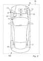
Fig. 3 illustrates thehost vehicle 50 with fourwheels 10 and thewheel suspension 30. For the sake of clarity only onewheel brake 32 is illustrated, allwheels 10 can comprisewheel brakes 32, e.g. if disc-type and/or drum-type. Also afront axis 34 is illustrated. Thehost vehicle 50 comprises a main steering system which is arranged to allow a vehicle operator the steer thehost vehicle 50 in a known manner. - The
host vehicle 50 comprises asecondary steering system 36 arranged for differential braking of one or more of thewheel brakes 32. Thesecondary steering system 36 comprises a secondarysteering system unit 40. The secondarysteering system unit 40 can be arranged as a separate unit which is arranged to control thesecondary steering system 36 of thevehicle 50. The secondarysteering system unit 40 can also be arranged as an integrated part of thesecondary steering system 36 of thevehicle 50. - A
fault determination arrangement 41 is arranged to determine the presence of a fault in the main steering system of thehost vehicle 50. A fault may be detected e.g. by a fault signal from the EPAS or a steer and/or diagnose-unit related to the EPAS. A fault can also be determined by a difference between a steering angle thehost vehicle 50 are supposed to have and a steering angle thehost vehicle 50 actual has. A fault can also be determined in other ways. For example can a fault be determined if the actual motion of thehost vehicle 50 and/or the yaw rate are different from calculated values. - The secondary
steering system unit 40 and/or other parts of thesteering system 36 can comprise at least one processing unit. In some embodiments the one or more processing units are used for processing in several different vehicle systems. Some processing units may be dedicated to a specific processing task. The one or more processing units may be central processing units that carry out instructions of computer programs/software which when executed perform basic arithmetical, logical, and input/output operations. - In some embodiments the secondary
steering system unit 40 is connected to a navigation system comprised in thehost vehicle 50, to which a user can input a preferred host vehicle route. Such navigation system can comprise a positioning arrangement, which may determine a host vehicle position and heading. The positioning system can determine the host vehicle position and driving direction e.g. via a satellite based global positioning system or via map matching and a compass. - The
host vehicle 50 can have autonomous steering capabilities. In such embodiments thehost vehicle 50 comprises an autonomous drive arrangement, sensors and a communication unit. Thehost vehicle 50 may then be referred to as an autonomous vehicle. The autonomous drive arrangement allows thehost vehicle 50 to be driven autonomously along a route or a road. The autonomous drive arrangement normally comprises an electrical/mechanical control arrangement, arranged to control steering and velocity of thehost vehicle 50 at least partly based on information received from the sensors. The autonomous drive arrangement is connected to the main steering system, such that the autonomous drive arrangement, directly or indirectly, can control a direction of at least some of thewheels 10 of thehost vehicle 50. Hereby e.g. a yaw rate of thehost vehicle 50 can be adjusted, such that the driving direction of thehost vehicle 50 is adjusted in accordance with the input from the autonomous drive arrangement. The autonomous drive arrangement is also connected to a host vehicle engine and a host vehicle braking system which comprises thewheel brakes 32. - Hereby the autonomous drive arrangement, directly or indirectly, can control acceleration and/or deceleration of the
host vehicle 50. The autonomous drive arrangement can e.g. increase a host vehicle velocity by increasing the engine speed, and decrease the host vehicle velocity by motor-braking or by activation of one or more of thewheel brakes 32. The autonomous drive arrangement may e.g. be connected to an ABS (anti-lock braking system), such that one ormore wheel brakes 32 can be activated selectively. - In some embodiments the
host vehicle 50 comprises a number of vehicle subsystems which may provide some automatic- or semi-automatic drive functions. Examples of such subsystem are: adaptive cruise control systems, lane departure control systems, collision avoidance systems, traffic sign recognition systems, some communication systems, some navigation systems, ultrasonic sensor systems, infrared camera systems, inertial measuring systems, intelligent transportation systems, safe road train systems, automatic parking systems etc. - The sensor or sensors of the
host vehicle 50 can be one or more camera sensors, one or more radar sensors and/or one or more lidar-sensors. The sensors can be arranged at any position in/on thehost vehicle 50 from where detection of a vehicle surrounding is possible. - The
host vehicle 50 can further comprise a communication unit. The communication unit may comprise a receiver that receives signals from at least one external source, such as surrounding vehicles, and converts them to information, such as real time information relating to preceding vehicle velocity, acceleration, braking, lane selection, statuses, heading etc. The receiver may also be configured to communicate with external sources in form of infrastructure such as remote servers/the cloud, databases, and/or roadside units. The communication unit may also comprise a transmitter which converts real time host vehicle information, e.g. relating to host vehicle velocity, acceleration, braking, lane selection, statuses, heading etc. into a signal, such as an electrical signal and/or a signal carried by electromagnetic waves. Herebyhost vehicle 50 information may be distributed to other vehicles and/or infrastructure such as remote servers/the cloud, databases, and/or roadside units. Any suitable means may be used for the communication between thehost vehicle 50 and other vehicles or infrastructure, e.g. radio signals, such as according to either of standards, such as the GSM, 3G, LTE and/or WiFi standards, and/or satellite communication signals. - A
path controller 42 is connected to the above described processing units, the sensors and/or the communication arrangement. Information received from the sensors and information received via the communication arrangement is thus provided to thepath controller 42. Thepath controller 42 is arranged to generate an upcoming path for thehost vehicle 50 based on sensor information and/or communicated information. - The generated upcoming path is a suitable path or trajectory that the
host vehicle 50 should follow in order to come to a safe stop. When generating the path, care is thus taken to avoid any stationary or moving objects in front of thehost vehicle 50. Care is also taken to the road on which thehost vehicle 50 travels, and possibly also to a road environment near the road. - According to some embodiments the
steering system 36 comprises a steeringangle control arrangement 44 which is arranged to keep a current steering wheel angle during the differential braking. The steeringangle control arrangement 44 comprises a friction element, an elastic element such as a pretension-spring or similar which is arranged to keep a current steering wheel angle during differential braking. With such a steering angle control arrangement 44 a larger curvature can be achieved, i.e. thehost vehicle 50 can be steered to follow a generated path with smaller radius also when the scrub radius is negative or substantially zero. -
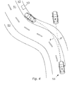
Fig. 4 illustrates thehost vehicle 50 in a road environment. In position A it is determined, by the fault determination arrangement, the presence of a fault in the main steering system. If no action would be taken, i.e. if no response to the fault in the main steering system is initiated, thehost vehicle 50 would most probably continue more or less straight ahead along path P' until departure of theroad 51 orroadside 52. This is illustrated with position B. - In embodiments described herein the path controller is arranged to generate an upcoming path P for the
host vehicle 50 based on information received from the sensors and/or information received via the communication arrangement. The path P can be referred to as an optimal path or preferred path, i.e. a path thehost vehicle 50 can follow without departure from theroad 51 and/or theroadside 52. In some situations the path can generate a path P which includes road and/or roadside departure if this is considered to be the best path. This may be the case e.g. if a surface next to theroad 51 and/orroadside 52 is flat and free from obstacles. - The secondary steering system unit is arranged to steer the
host vehicle 50 along the upcoming path P by activation of differential braking of at least one wheel brake upon determination that a fault is present in the main steering system. InFig. 4 thehost vehicle 50 is steered to position C on theroadside 52. The position C is considered to be a relatively safe position for thehost vehicle 50 to stop. Due to the received or detected information on the host vehicle surrounding, moving orstationary objects 53 can be considered when the path P is generated. - In the upper part of
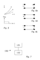
Fig. 5 is illustrates a possible lateral displacement for different scrub radiuses and in the lower part ofFig. 5 is brake force F(t) as a function on braking time t illustrated. - Curvature i corresponds to a negative scrub radius. This curvature is relatively modest, which means that a curvature of a path generated by the path generator cannot be larger than curve i with a negative scrub radius since the host vehicle cannot follow such a path. The scenario illustrated by the curve ii in
Fig. 5 , corresponds to a negative or very small scrub radius when a steeringangle control arrangement 44 is used. - In embodiments with a wheel suspension where the scrub radius is positive and the magnitude is "sufficiently large" a relatively large curvature of the generated path can be followed by the
host vehicle 50. The scrub radius affects the possibility for the host vehicle to follow the generated path. Since also other factors, such as wheel suspension design, affect the possibility for the host vehicle to follow the generated path, the magnitude of the scrub radius has to be designed and/or selected e.g. depending on the kind of wheel suspension the host vehicle is equipped with. - "Sufficiently large" for the scrub radius can thus be different for different host vehicles and/or wheel suspensions. In some embodiments the scrub radius should be large enough to be able the control the steering angle by braking one front wheel. In some embodiments a scrub radius which is at least 10 millimetres is sufficient for allowing the host vehicle to follow a desired number of generated paths. In some embodiment the scrub radius is at least 20 millimetres, and in some embodiments the scrub radius is at least 30 millimetres.
- The curve iii in
Fig. 5 illustrates a path which is possible to follow with a positive scrub radius. The host vehicle's side motion is then controlled by induced yaw torque and steering angle from braking inner wheel or wheels. This can give the largest curvature among the three examples above. -
Fig. 6 illustrates the wheel angles corresponding to the curves i, ii and iii inFig. 5 . The wheel angle inFig. 6a is a result of a positive scrub radius when the host vehicle is differentially braked, and causes the curve iii inFig. 5 . The wheel is forced to turn towards the differentially braked side. This is also referred to as toe-out effect. -
Fig. 6b illustrates the host vehicle wheels when differentially braked and with a negative or very small scrub radius. In the 6b embodiment a spring and/or an elastic element is attached to the wheel suspension, forcing the wheels to not turn left or right. This scenario corresponds to curve ii ofFig. 5. Fig. 6c illustrates the host vehicle wheels when differentially braked and with a negative or very small scrub radius. This scenario corresponds to curve i ofFig. 5 . -
Fig. 7 illustrates amethod 100 for secondary steering of a host vehicle having autonomous steering capabilities, the host vehicle comprising a main steering system with a steering actuator for providing an overlay torque to the steering system which is sufficient to steer at least one pair of host vehicle steerable wheels. The host vehicle further has a brake system comprising a respective wheel brake associated with a respective vehicle wheel which is suspended by a respective wheel suspension, - The host vehicle comprises one or more sensors and a communication arrangement for acquiring vehicle surrounding information, the secondary steering system unit comprising a fault determination arrangement, arranged to determine the presence of a fault in the main steering system and a path controller. The path controller is arranged to generate an upcoming path for the host vehicle based on at least information received from the sensors and information received via the communication arrangement.
- The secondary steering system unit is arranged to steer the host vehicle along the upcoming path by activation of differential braking of at least one wheel brake upon determination that a fault is present in the main steering system.
- The
method 100 comprises: - steering 101, by the secondary steering system, the differential braking in dependence of a yaw torque acting on the host vehicle as a result of the differential braking and simultaneously,
- steering 102, by the secondary steering system, the differential braking in dependence of a steering angle resulting from a generated alignment torque on a braked steerable wheel caused by the associated wheel suspension scrub radius.
Claims (11)
- A secondary steering system unit (40) for a host vehicle (50) having autonomous steering capabilities comprising a main steering system comprising a steering actuator for providing an overlay torque to the steering system which is sufficient to steer at least one pair of host vehicle steerable wheels, the host vehicle (50) further having a brake system comprising a respective wheel brake (32) associated with a respective vehicle wheel (10) which is suspended by a respective wheel suspension (30), the host vehicle (50) further comprising one or more sensors and a communication arrangement for acquiring vehicle surrounding information, the secondary steering system unit (40) comprising:- a fault determination arrangement (41), arranged to determine the presence of a fault in the main steering system,- a path controller (42), arranged to generate an upcoming path (P) for the host vehicle (50) based on at least one of information received from the sensors and information received via the communication arrangement,
the secondary steering system unit (40) being arranged to steer the host vehicle (50) along the upcoming path (P) by activation of differential braking of at least one wheel brake (10) upon determination that a fault is present in the main steering system, characterized in that the secondary steering system unit (40) is arranged to steer the differential braking in dependence of both- a yaw torque (T) acting on the host vehicle (50) as a result of the differential braking and- a steering angle resulting from a generated alignment torque on a braked steerable wheel (10) caused by the associated wheel suspension scrub radius (27). - A secondary steering system (36) comprising host vehicle wheels (10), wheel suspension (30) and wheel brakes (10), and wherein the secondary steering system (36) comprises a secondary steering system unit (40) according to claim 1.
- The secondary steering system (36) according to claim 2 wherein the scrub radius (27) is positive.
- The secondary steering system (36) according to claim 3 wherein the scrub radius (27) is at least 10 millimeters, preferably at least 20 millimeters, more preferably at least 30 millimeters.
- The secondary steering system (36) according to claim 3 or 4 wherein the scrub radius (27) is selected to be sufficiently large to cause a toe-out effect on a host vehicle wheel (10) which is differentially braked.
- The secondary steering system (36) according to any one of claims 2-5 wherein the wheel suspension (30) comprises double wishbones.
- The secondary steering system (36) according to claim 2 wherein the scrub radius (27) is negative or substantially zero.
- The secondary steering system (36) according to claim 7 wherein the system (36) comprises a steering angle control arrangement (44) which is arranged to keep a current steering wheel angle during differential braking.
- The secondary steering system (36) according to claim 8 wherein the steering angle control arrangement (44) comprises at least one of a friction element and a spring which is arranged to keep the current steering wheel angle during differential braking.
- A vehicle (50), characterized in that the vehicle comprises a secondary steering system unit (40) according to claim 1 or a secondary steering system (36) according to any one of claims 2-9.
- A method (100) for secondary steering of a host vehicle (50) having autonomous steering capabilities, the host vehicle (50) comprising a main steering system with a steering actuator for providing an overlay torque to the steering system which is sufficient to steer at least one pair of host vehicle steerable wheels (10), the host vehicle (50) further having a brake system comprising a respective wheel brake (10) associated with a respective vehicle wheel (32) which is suspended by a respective wheel suspension (30), the host vehicle (50) further comprising one or more sensors and a communication arrangement for acquiring vehicle surrounding information, the secondary steering system unit (40) comprising a fault determination arrangement (41), arranged to determine the presence of a fault in the main steering system and a path controller (42), arranged to generate an upcoming path (P) for the host vehicle (50) based on at least one of information received from the sensors and information received via the communication arrangement, the secondary steering system unit (40) being arranged to steer the host vehicle (50) along the upcoming path (P) by activation of differential braking of at least one wheel brake (32) upon determination that a fault is present in the main steering system, characterized in that the method (100) comprises:- steering (101), by the secondary steering system (30), the differential braking in dependence of a yaw torque acting on the host vehicle (50) as a result of the differential braking and simultaneously,- steering (102), by the secondary steering system (30), the differential braking in dependence of a steering angle resulting from a generated alignment torque on a braked steerable wheel (10) caused by the associated wheel suspension scrub radius (27).
Priority Applications (3)
| Application Number | Priority Date | Filing Date | Title |
|---|---|---|---|
| EP15166329.1A EP3090907B1 (en) | 2015-05-05 | 2015-05-05 | Secondary steering system unit, secondary steering system, vehicle and a method for secondary steering |
| CN201610267204.0A CN106125722B (en) | 2015-05-05 | 2016-04-27 | Auxiliary steering system unit, auxiliary steering system, vehicle and auxiliary steering method |
| US15/139,413 US10046743B2 (en) | 2015-05-05 | 2016-04-27 | Secondary steering system unit, secondary steering system, vehicle and a method for secondary steering |
Applications Claiming Priority (1)
| Application Number | Priority Date | Filing Date | Title |
|---|---|---|---|
| EP15166329.1A EP3090907B1 (en) | 2015-05-05 | 2015-05-05 | Secondary steering system unit, secondary steering system, vehicle and a method for secondary steering |
Publications (2)
| Publication Number | Publication Date |
|---|---|
| EP3090907A1 true EP3090907A1 (en) | 2016-11-09 |
| EP3090907B1 EP3090907B1 (en) | 2020-08-12 |
Family
ID=53040429
Family Applications (1)
| Application Number | Title | Priority Date | Filing Date |
|---|---|---|---|
| EP15166329.1A Active EP3090907B1 (en) | 2015-05-05 | 2015-05-05 | Secondary steering system unit, secondary steering system, vehicle and a method for secondary steering |
Country Status (3)
| Country | Link |
|---|---|
| US (1) | US10046743B2 (en) |
| EP (1) | EP3090907B1 (en) |
| CN (1) | CN106125722B (en) |
Cited By (8)
| Publication number | Priority date | Publication date | Assignee | Title |
|---|---|---|---|---|
| DE102016001592A1 (en) * | 2016-02-11 | 2017-08-17 | Audi Ag | Method for influencing the direction of travel of motor vehicles |
| FR3067321A1 (en) * | 2017-06-12 | 2018-12-14 | Foundation Brakes France | MODIFICATION OF THE TRACK OF A VEHICLE WHEEL IN THE EVENT OF A STEERING SYSTEM FAILURE |
| WO2020089270A1 (en) * | 2018-10-31 | 2020-05-07 | Fraunhofer-Gesellschaft zur Förderung der angewandten Forschung e.V. | Concept for carrying out an emergency stop manoeuvre |
| EP3653457A1 (en) * | 2018-11-16 | 2020-05-20 | Volkswagen AG | Braking system for a motor vehicle, motor vehicle equipped therewith and method for operating said braking system |
| WO2022219103A1 (en) * | 2021-04-15 | 2022-10-20 | National Electric Vehicle Sweden Ab | Method for emergency steering and emergency steering system |
| WO2023280394A1 (en) * | 2021-07-07 | 2023-01-12 | Volvo Autonomous Solutions AB | A method of controlling a backup motion control system |
| EP4265493A1 (en) * | 2022-04-21 | 2023-10-25 | Volvo Car Corporation | Path planning during steer-by-brake or steer-by-torque vectoring |
| WO2023202807A1 (en) * | 2022-04-20 | 2023-10-26 | Daimler Truck AG | Method for operating a driver assistance system of a utility vehicle |
Families Citing this family (26)
| Publication number | Priority date | Publication date | Assignee | Title |
|---|---|---|---|---|
| EP3305620B1 (en) * | 2015-06-03 | 2019-08-07 | Nissan Motor Co., Ltd. | Vehicle control device and vehicle control method |
| EP3293065B1 (en) * | 2016-09-12 | 2021-02-24 | KNORR-BREMSE Systeme für Nutzfahrzeuge GmbH | Steering control system and a method for controlling steering |
| EP3293064B1 (en) * | 2016-09-12 | 2021-03-10 | KNORR-BREMSE Systeme für Nutzfahrzeuge GmbH | Steering control system and a method for controlling steering |
| JP6654121B2 (en) * | 2016-09-23 | 2020-02-26 | 日立オートモティブシステムズ株式会社 | Vehicle motion control device |
| US10395441B2 (en) * | 2016-12-14 | 2019-08-27 | Uber Technologies, Inc. | Vehicle management system |
| US9811086B1 (en) | 2016-12-14 | 2017-11-07 | Uber Technologies, Inc. | Vehicle management system |
| CN106741138B (en) * | 2016-12-16 | 2019-02-19 | 吉林大学 | A kind of the multi-mode steering system and control method of electric wheel drive vehicle |
| US9925988B1 (en) * | 2017-02-24 | 2018-03-27 | Flord Global Technologies, Llc | Steering and braking control system |
| US20190054915A1 (en) * | 2017-08-16 | 2019-02-21 | Deere & Company | Service Brake Assist Steering |
| SE541786C2 (en) * | 2017-08-28 | 2019-12-17 | Scania Cv Ab | A method for providing vehicle steering support by differential wheel braking, a system, a vehicle, a computer program and a computer-readable medium. |
| CN109703546A (en) * | 2017-10-25 | 2019-05-03 | 上汽通用汽车有限公司 | Vehicular turn failure operating system and its control method |
| US10685505B2 (en) * | 2017-11-28 | 2020-06-16 | GM Global Technology Operations LLC | Vehicle suspension system alignment monitoring |
| DE102017221968A1 (en) * | 2017-12-05 | 2019-06-19 | Volkswagen Aktiengesellschaft | Method for operating a steering device and steering device |
| US20190168803A1 (en) * | 2017-12-06 | 2019-06-06 | Trw Automotive U.S. Llc | Method of controlling a vehicle in case of steering system failure |
| DE102018106889A1 (en) * | 2018-03-09 | 2019-09-12 | Knorr-Bremse Systeme für Nutzfahrzeuge GmbH | Steering method for an autonomously steered vehicle |
| JP6866867B2 (en) * | 2018-03-27 | 2021-04-28 | トヨタ自動車株式会社 | Vehicle control system |
| JP7017130B2 (en) | 2018-08-13 | 2022-02-08 | トヨタ自動車株式会社 | Steering system |
| EP3626555B1 (en) * | 2018-09-18 | 2022-07-20 | KNORR-BREMSE Systeme für Nutzfahrzeuge GmbH | Control architecture for electrified braking and electrified steering of a vehicle |
| EP3983277A1 (en) * | 2019-06-11 | 2022-04-20 | Volvo Truck Corporation | A method for estimating a longitudinal force difference acting on steered wheels |
| CN112477977A (en) * | 2019-09-12 | 2021-03-12 | 比亚迪股份有限公司 | Vehicle power-assisted steering device and control method thereof |
| US20210086737A1 (en) * | 2019-09-19 | 2021-03-25 | Continental Automotive Systems, Inc. | Vehicle wheel steer control system and method |
| KR20210148635A (en) * | 2020-06-01 | 2021-12-08 | 현대모비스 주식회사 | Method And Apparatus for Vehicle Braking |
| US11634160B2 (en) | 2020-08-14 | 2023-04-25 | Waymo Llc | Thermal management of steering system for autonomous vehicles |
| KR20220048524A (en) * | 2020-10-12 | 2022-04-20 | 현대자동차주식회사 | Vehicle movement method after accident of autonomous vehicle |
| US20230121593A1 (en) * | 2021-10-18 | 2023-04-20 | Steering Solutions Ip Holding Corporation | Differential braking to reduce steering effort during electric power steering loss of assist |
| CN116215656A (en) * | 2023-03-10 | 2023-06-06 | 浙江吉利控股集团有限公司 | Vehicle, control method and control device thereof, and storage medium |
Citations (5)
| Publication number | Priority date | Publication date | Assignee | Title |
|---|---|---|---|---|
| GB2383983A (en) * | 2002-01-11 | 2003-07-16 | Roger Aylward | Automatic steering, braking and backup guidance system |
| DE102008046007A1 (en) * | 2008-09-05 | 2010-03-18 | Man Nutzfahrzeuge Ag | Power steering device for motor vehicle, particularly commercial vehicle, has two axles, of which one axle is hinged by servo steering, and kingpin inclination is formed such that steering axle is inclined in vehicle vertical axis direction |
| US20110246040A1 (en) * | 2010-03-30 | 2011-10-06 | Fuji Jukogyo Kabushiki Kaisha | Vehicular lane departure prevention control apparatus |
| US20120226417A1 (en) * | 2010-04-14 | 2012-09-06 | Toyota Jidosha Kabushiki Kaisha | Control apparatus for vehicle |
| US20130030651A1 (en) | 2011-07-25 | 2013-01-31 | GM Global Technology Operations LLC | Collision avoidance maneuver through differential braking |
Family Cites Families (28)
| Publication number | Priority date | Publication date | Assignee | Title |
|---|---|---|---|---|
| US5348334A (en) * | 1993-08-06 | 1994-09-20 | Ford Motor Company | Suspension apparatus for a motor vehicle |
| WO1999030956A1 (en) * | 1997-12-12 | 1999-06-24 | Holland Neway International, Inc. | Independent front suspension |
| US6418856B2 (en) * | 1999-11-11 | 2002-07-16 | Raytheon Company | Passive steering assembly for a guided vehicle |
| US6560883B2 (en) * | 2000-06-28 | 2003-05-13 | Snap-On Technologies, Inc. | Method and system for conducting wheel alignment |
| US6672985B2 (en) * | 2001-08-30 | 2004-01-06 | Axletech International Ip Holdings, Llc | Independently rotating wheels with planetary drive |
| US6890039B2 (en) * | 2002-03-06 | 2005-05-10 | Axletech International Ip Holdings, Llc | Independently rotating wheels |
| JP3986939B2 (en) * | 2002-10-25 | 2007-10-03 | 本田技研工業株式会社 | Brake device for vehicle |
| EP1649246A1 (en) * | 2003-07-31 | 2006-04-26 | Snap-on Incorporated | Two-wheel alignment adjustment method |
| US7486705B2 (en) * | 2004-03-31 | 2009-02-03 | Imra America, Inc. | Femtosecond laser processing system with process parameters, controls and feedback |
| JP4042979B2 (en) * | 2004-05-14 | 2008-02-06 | 本田技研工業株式会社 | Vehicle operation support device |
| US7441788B2 (en) * | 2004-07-09 | 2008-10-28 | Bombardier Recreational Products Inc. | Front drive geometry for an all-terrain vehicle |
| US7328124B2 (en) * | 2004-10-07 | 2008-02-05 | Hunter Engineering Company | Apparatus and method for measuring and compensating steering-angle sensitive alignment measurements |
| US7331211B2 (en) * | 2005-02-10 | 2008-02-19 | Mitchell Craig Harrill | Apparatus for measuring suspension parameters which include roll center |
| US7617890B2 (en) * | 2006-05-08 | 2009-11-17 | Deere & Company | Steering mechanism for self-propelled mower |
| US7418328B2 (en) * | 2006-05-08 | 2008-08-26 | Deere & Company | Steering logic for self-propelled mower |
| JP4706654B2 (en) * | 2007-03-27 | 2011-06-22 | トヨタ自動車株式会社 | Collision avoidance device |
| US7640673B2 (en) * | 2007-08-01 | 2010-01-05 | Snap-On Incorporated | Calibration and operation of wheel alignment systems |
| JP5174609B2 (en) * | 2008-10-10 | 2013-04-03 | 日立オートモティブシステムズ株式会社 | Driving support device |
| US8831854B2 (en) * | 2010-08-16 | 2014-09-09 | Chrysler Group Llc | Active shimmy mitigation |
| US9514647B2 (en) * | 2010-10-20 | 2016-12-06 | GM Global Technology Operations LLC | Optimal acceleration profile for enhanced collision avoidance |
| US8527172B2 (en) * | 2010-10-20 | 2013-09-03 | GM Global Technology Operations LLC | Vehicle collision avoidance and warning system |
| US9499193B2 (en) * | 2010-11-29 | 2016-11-22 | Nissan Motor Co., Ltd. | Vehicle, and method for steering control of same |
| WO2012124272A1 (en) * | 2011-03-16 | 2012-09-20 | 日産自動車株式会社 | Suspension device for vehicle, method for adjusting geometry of same, and automobile |
| US8670903B2 (en) * | 2011-05-05 | 2014-03-11 | GM Global Technology Operations LLC | Lane centering fail-safe control using differential braking |
| JP5910747B2 (en) * | 2012-07-20 | 2016-05-11 | 日産自動車株式会社 | Vehicle suspension device, automobile using the same, and steering control method |
| JP5900659B2 (en) * | 2013-01-11 | 2016-04-06 | 日産自動車株式会社 | Vehicle travel control apparatus and vehicle travel control method |
| CN104276155B (en) * | 2014-08-20 | 2017-10-24 | 浙江科技学院 | It is a kind of based on left and right Electric Motor Wheel it is differential/the Control of Electric Vehicles method of control for brake |
| US9592850B1 (en) * | 2016-04-22 | 2017-03-14 | Denso Corporation | Steering control apparatus |
-
2015
- 2015-05-05 EP EP15166329.1A patent/EP3090907B1/en active Active
-
2016
- 2016-04-27 CN CN201610267204.0A patent/CN106125722B/en active Active
- 2016-04-27 US US15/139,413 patent/US10046743B2/en active Active
Patent Citations (5)
| Publication number | Priority date | Publication date | Assignee | Title |
|---|---|---|---|---|
| GB2383983A (en) * | 2002-01-11 | 2003-07-16 | Roger Aylward | Automatic steering, braking and backup guidance system |
| DE102008046007A1 (en) * | 2008-09-05 | 2010-03-18 | Man Nutzfahrzeuge Ag | Power steering device for motor vehicle, particularly commercial vehicle, has two axles, of which one axle is hinged by servo steering, and kingpin inclination is formed such that steering axle is inclined in vehicle vertical axis direction |
| US20110246040A1 (en) * | 2010-03-30 | 2011-10-06 | Fuji Jukogyo Kabushiki Kaisha | Vehicular lane departure prevention control apparatus |
| US20120226417A1 (en) * | 2010-04-14 | 2012-09-06 | Toyota Jidosha Kabushiki Kaisha | Control apparatus for vehicle |
| US20130030651A1 (en) | 2011-07-25 | 2013-01-31 | GM Global Technology Operations LLC | Collision avoidance maneuver through differential braking |
Cited By (13)
| Publication number | Priority date | Publication date | Assignee | Title |
|---|---|---|---|---|
| EP3414145B1 (en) * | 2016-02-11 | 2020-09-23 | Audi AG | Method for influencing the direction of travel of motor vehicles |
| US10518808B2 (en) | 2016-02-11 | 2019-12-31 | Audi Ag | Method for influencing the direction of travel of motor vehicles |
| DE102016001592A1 (en) * | 2016-02-11 | 2017-08-17 | Audi Ag | Method for influencing the direction of travel of motor vehicles |
| FR3067321A1 (en) * | 2017-06-12 | 2018-12-14 | Foundation Brakes France | MODIFICATION OF THE TRACK OF A VEHICLE WHEEL IN THE EVENT OF A STEERING SYSTEM FAILURE |
| WO2018229412A1 (en) * | 2017-06-12 | 2018-12-20 | Foundation Brakes France | Modification of the trajectory of a vehicle wheel in the event of steering system failure |
| US11247722B2 (en) | 2017-06-12 | 2022-02-15 | Foundation Brakes France | Modification of the trajectory of a vehicle wheel in the event of steering system failure |
| WO2020089270A1 (en) * | 2018-10-31 | 2020-05-07 | Fraunhofer-Gesellschaft zur Förderung der angewandten Forschung e.V. | Concept for carrying out an emergency stop manoeuvre |
| EP3653457A1 (en) * | 2018-11-16 | 2020-05-20 | Volkswagen AG | Braking system for a motor vehicle, motor vehicle equipped therewith and method for operating said braking system |
| US11491969B2 (en) | 2018-11-16 | 2022-11-08 | Volkswagen Aktiengesellschaft | Brake system for detecting defects for a transportation vehicle, transportation vehicle with a brake system for detecting defects, and method for operating a brake system for detecting defects |
| WO2022219103A1 (en) * | 2021-04-15 | 2022-10-20 | National Electric Vehicle Sweden Ab | Method for emergency steering and emergency steering system |
| WO2023280394A1 (en) * | 2021-07-07 | 2023-01-12 | Volvo Autonomous Solutions AB | A method of controlling a backup motion control system |
| WO2023202807A1 (en) * | 2022-04-20 | 2023-10-26 | Daimler Truck AG | Method for operating a driver assistance system of a utility vehicle |
| EP4265493A1 (en) * | 2022-04-21 | 2023-10-25 | Volvo Car Corporation | Path planning during steer-by-brake or steer-by-torque vectoring |
Also Published As
| Publication number | Publication date |
|---|---|
| CN106125722A (en) | 2016-11-16 |
| CN106125722B (en) | 2020-11-17 |
| EP3090907B1 (en) | 2020-08-12 |
| US20160325721A1 (en) | 2016-11-10 |
| US10046743B2 (en) | 2018-08-14 |
Similar Documents
| Publication | Publication Date | Title |
|---|---|---|
| EP3090907B1 (en) | Secondary steering system unit, secondary steering system, vehicle and a method for secondary steering | |
| EP3694766B1 (en) | Method for controlling a steering system of a vehicle | |
| US8781684B2 (en) | Steering and control systems for a three-wheeled vehicle | |
| CN103029703B (en) | The lane changing aid system of vehicle and method thereof | |
| US20180164821A1 (en) | Test method and system using a highly agile ground vehicle for intelligent vehicle testing | |
| CN101537853B (en) | Automobile four-wheel active steering control system | |
| CN107735311B (en) | Method for steering a vehicle, control device for a motor vehicle, and motor vehicle | |
| CN109435946A (en) | Vehicle and its avoidance obstacle method, system, electronic equipment and storage medium | |
| CN106080753A (en) | A kind of Electric Motor Wheel steering control system merging active steering, power-assisted steering and direct yaw moment control function and control method thereof | |
| EP2923924B1 (en) | Driver assist arrangement | |
| CN109591805A (en) | Intelligence is blown out electric stabilizing system | |
| US11161545B2 (en) | Steering control system and a method for controlling steering | |
| US20230278625A1 (en) | Method for controlling steering of a vehicle arrangement | |
| US9878740B2 (en) | Active steering system for articulated bus | |
| US11097766B2 (en) | Actuating part and control for a motor vehicle | |
| WO2014016947A1 (en) | Vehicle control system and control unit | |
| KR102572642B1 (en) | Device and method for impact buffer of vehicle | |
| CA3215540A1 (en) | Method for emergency steering and emergency steering system |
Legal Events
| Date | Code | Title | Description |
|---|---|---|---|
| PUAI | Public reference made under article 153(3) epc to a published international application that has entered the european phase |
Free format text: ORIGINAL CODE: 0009012 |
|
| AK | Designated contracting states |
Kind code of ref document: A1 Designated state(s): AL AT BE BG CH CY CZ DE DK EE ES FI FR GB GR HR HU IE IS IT LI LT LU LV MC MK MT NL NO PL PT RO RS SE SI SK SM TR |
|
| AX | Request for extension of the european patent |
Extension state: BA ME |
|
| STAA | Information on the status of an ep patent application or granted ep patent |
Free format text: STATUS: REQUEST FOR EXAMINATION WAS MADE |
|
| 17P | Request for examination filed |
Effective date: 20170509 |
|
| RBV | Designated contracting states (corrected) |
Designated state(s): AL AT BE BG CH CY CZ DE DK EE ES FI FR GB GR HR HU IE IS IT LI LT LU LV MC MK MT NL NO PL PT RO RS SE SI SK SM TR |
|
| GRAP | Despatch of communication of intention to grant a patent |
Free format text: ORIGINAL CODE: EPIDOSNIGR1 |
|
| STAA | Information on the status of an ep patent application or granted ep patent |
Free format text: STATUS: GRANT OF PATENT IS INTENDED |
|
| RIC1 | Information provided on ipc code assigned before grant |
Ipc: B62D 11/08 20060101ALI20200226BHEP Ipc: B60T 8/1755 20060101AFI20200226BHEP |
|
| INTG | Intention to grant announced |
Effective date: 20200320 |
|
| GRAS | Grant fee paid |
Free format text: ORIGINAL CODE: EPIDOSNIGR3 |
|
| GRAA | (expected) grant |
Free format text: ORIGINAL CODE: 0009210 |
|
| STAA | Information on the status of an ep patent application or granted ep patent |
Free format text: STATUS: THE PATENT HAS BEEN GRANTED |
|
| AK | Designated contracting states |
Kind code of ref document: B1 Designated state(s): AL AT BE BG CH CY CZ DE DK EE ES FI FR GB GR HR HU IE IS IT LI LT LU LV MC MK MT NL NO PL PT RO RS SE SI SK SM TR |
|
| REG | Reference to a national code |
Ref country code: CH Ref legal event code: EP |
|
| REG | Reference to a national code |
Ref country code: IE Ref legal event code: FG4D |
|
| REG | Reference to a national code |
Ref country code: DE Ref legal event code: R096 Ref document number: 602015057257 Country of ref document: DE |
|
| REG | Reference to a national code |
Ref country code: AT Ref legal event code: REF Ref document number: 1301270 Country of ref document: AT Kind code of ref document: T Effective date: 20200915 |
|
| REG | Reference to a national code |
Ref country code: LT Ref legal event code: MG4D |
|
| REG | Reference to a national code |
Ref country code: NL Ref legal event code: MP Effective date: 20200812 |
|
| PG25 | Lapsed in a contracting state [announced via postgrant information from national office to epo] |
Ref country code: FI Free format text: LAPSE BECAUSE OF FAILURE TO SUBMIT A TRANSLATION OF THE DESCRIPTION OR TO PAY THE FEE WITHIN THE PRESCRIBED TIME-LIMIT Effective date: 20200812 Ref country code: LT Free format text: LAPSE BECAUSE OF FAILURE TO SUBMIT A TRANSLATION OF THE DESCRIPTION OR TO PAY THE FEE WITHIN THE PRESCRIBED TIME-LIMIT Effective date: 20200812 Ref country code: BG Free format text: LAPSE BECAUSE OF FAILURE TO SUBMIT A TRANSLATION OF THE DESCRIPTION OR TO PAY THE FEE WITHIN THE PRESCRIBED TIME-LIMIT Effective date: 20201112 Ref country code: GR Free format text: LAPSE BECAUSE OF FAILURE TO SUBMIT A TRANSLATION OF THE DESCRIPTION OR TO PAY THE FEE WITHIN THE PRESCRIBED TIME-LIMIT Effective date: 20201113 Ref country code: NO Free format text: LAPSE BECAUSE OF FAILURE TO SUBMIT A TRANSLATION OF THE DESCRIPTION OR TO PAY THE FEE WITHIN THE PRESCRIBED TIME-LIMIT Effective date: 20201112 Ref country code: HR Free format text: LAPSE BECAUSE OF FAILURE TO SUBMIT A TRANSLATION OF THE DESCRIPTION OR TO PAY THE FEE WITHIN THE PRESCRIBED TIME-LIMIT Effective date: 20200812 Ref country code: SE Free format text: LAPSE BECAUSE OF FAILURE TO SUBMIT A TRANSLATION OF THE DESCRIPTION OR TO PAY THE FEE WITHIN THE PRESCRIBED TIME-LIMIT Effective date: 20200812 |
|
| REG | Reference to a national code |
Ref country code: AT Ref legal event code: MK05 Ref document number: 1301270 Country of ref document: AT Kind code of ref document: T Effective date: 20200812 |
|
| PG25 | Lapsed in a contracting state [announced via postgrant information from national office to epo] |
Ref country code: RS Free format text: LAPSE BECAUSE OF FAILURE TO SUBMIT A TRANSLATION OF THE DESCRIPTION OR TO PAY THE FEE WITHIN THE PRESCRIBED TIME-LIMIT Effective date: 20200812 Ref country code: LV Free format text: LAPSE BECAUSE OF FAILURE TO SUBMIT A TRANSLATION OF THE DESCRIPTION OR TO PAY THE FEE WITHIN THE PRESCRIBED TIME-LIMIT Effective date: 20200812 Ref country code: NL Free format text: LAPSE BECAUSE OF FAILURE TO SUBMIT A TRANSLATION OF THE DESCRIPTION OR TO PAY THE FEE WITHIN THE PRESCRIBED TIME-LIMIT Effective date: 20200812 Ref country code: PL Free format text: LAPSE BECAUSE OF FAILURE TO SUBMIT A TRANSLATION OF THE DESCRIPTION OR TO PAY THE FEE WITHIN THE PRESCRIBED TIME-LIMIT Effective date: 20200812 Ref country code: IS Free format text: LAPSE BECAUSE OF FAILURE TO SUBMIT A TRANSLATION OF THE DESCRIPTION OR TO PAY THE FEE WITHIN THE PRESCRIBED TIME-LIMIT Effective date: 20201212 |
|
| PG25 | Lapsed in a contracting state [announced via postgrant information from national office to epo] |
Ref country code: SM Free format text: LAPSE BECAUSE OF FAILURE TO SUBMIT A TRANSLATION OF THE DESCRIPTION OR TO PAY THE FEE WITHIN THE PRESCRIBED TIME-LIMIT Effective date: 20200812 Ref country code: RO Free format text: LAPSE BECAUSE OF FAILURE TO SUBMIT A TRANSLATION OF THE DESCRIPTION OR TO PAY THE FEE WITHIN THE PRESCRIBED TIME-LIMIT Effective date: 20200812 Ref country code: EE Free format text: LAPSE BECAUSE OF FAILURE TO SUBMIT A TRANSLATION OF THE DESCRIPTION OR TO PAY THE FEE WITHIN THE PRESCRIBED TIME-LIMIT Effective date: 20200812 Ref country code: CZ Free format text: LAPSE BECAUSE OF FAILURE TO SUBMIT A TRANSLATION OF THE DESCRIPTION OR TO PAY THE FEE WITHIN THE PRESCRIBED TIME-LIMIT Effective date: 20200812 Ref country code: DK Free format text: LAPSE BECAUSE OF FAILURE TO SUBMIT A TRANSLATION OF THE DESCRIPTION OR TO PAY THE FEE WITHIN THE PRESCRIBED TIME-LIMIT Effective date: 20200812 |
|
| REG | Reference to a national code |
Ref country code: DE Ref legal event code: R097 Ref document number: 602015057257 Country of ref document: DE |
|
| PG25 | Lapsed in a contracting state [announced via postgrant information from national office to epo] |
Ref country code: AL Free format text: LAPSE BECAUSE OF FAILURE TO SUBMIT A TRANSLATION OF THE DESCRIPTION OR TO PAY THE FEE WITHIN THE PRESCRIBED TIME-LIMIT Effective date: 20200812 Ref country code: AT Free format text: LAPSE BECAUSE OF FAILURE TO SUBMIT A TRANSLATION OF THE DESCRIPTION OR TO PAY THE FEE WITHIN THE PRESCRIBED TIME-LIMIT Effective date: 20200812 Ref country code: ES Free format text: LAPSE BECAUSE OF FAILURE TO SUBMIT A TRANSLATION OF THE DESCRIPTION OR TO PAY THE FEE WITHIN THE PRESCRIBED TIME-LIMIT Effective date: 20200812 |
|
| PLBE | No opposition filed within time limit |
Free format text: ORIGINAL CODE: 0009261 |
|
| STAA | Information on the status of an ep patent application or granted ep patent |
Free format text: STATUS: NO OPPOSITION FILED WITHIN TIME LIMIT |
|
| PG25 | Lapsed in a contracting state [announced via postgrant information from national office to epo] |
Ref country code: SK Free format text: LAPSE BECAUSE OF FAILURE TO SUBMIT A TRANSLATION OF THE DESCRIPTION OR TO PAY THE FEE WITHIN THE PRESCRIBED TIME-LIMIT Effective date: 20200812 |
|
| 26N | No opposition filed |
Effective date: 20210514 |
|
| PG25 | Lapsed in a contracting state [announced via postgrant information from national office to epo] |
Ref country code: SI Free format text: LAPSE BECAUSE OF FAILURE TO SUBMIT A TRANSLATION OF THE DESCRIPTION OR TO PAY THE FEE WITHIN THE PRESCRIBED TIME-LIMIT Effective date: 20200812 |
|
| REG | Reference to a national code |
Ref country code: CH Ref legal event code: PL |
|
| GBPC | Gb: european patent ceased through non-payment of renewal fee |
Effective date: 20210505 |
|
| PG25 | Lapsed in a contracting state [announced via postgrant information from national office to epo] |
Ref country code: LI Free format text: LAPSE BECAUSE OF NON-PAYMENT OF DUE FEES Effective date: 20210531 Ref country code: MC Free format text: LAPSE BECAUSE OF FAILURE TO SUBMIT A TRANSLATION OF THE DESCRIPTION OR TO PAY THE FEE WITHIN THE PRESCRIBED TIME-LIMIT Effective date: 20200812 Ref country code: LU Free format text: LAPSE BECAUSE OF NON-PAYMENT OF DUE FEES Effective date: 20210505 Ref country code: CH Free format text: LAPSE BECAUSE OF NON-PAYMENT OF DUE FEES Effective date: 20210531 |
|
| REG | Reference to a national code |
Ref country code: BE Ref legal event code: MM Effective date: 20210531 |
|
| PG25 | Lapsed in a contracting state [announced via postgrant information from national office to epo] |
Ref country code: IE Free format text: LAPSE BECAUSE OF NON-PAYMENT OF DUE FEES Effective date: 20210505 Ref country code: GB Free format text: LAPSE BECAUSE OF NON-PAYMENT OF DUE FEES Effective date: 20210505 |
|
| PG25 | Lapsed in a contracting state [announced via postgrant information from national office to epo] |
Ref country code: BE Free format text: LAPSE BECAUSE OF NON-PAYMENT OF DUE FEES Effective date: 20210531 |
|
| PG25 | Lapsed in a contracting state [announced via postgrant information from national office to epo] |
Ref country code: PT Free format text: LAPSE BECAUSE OF FAILURE TO SUBMIT A TRANSLATION OF THE DESCRIPTION OR TO PAY THE FEE WITHIN THE PRESCRIBED TIME-LIMIT Effective date: 20201214 |
|
| PG25 | Lapsed in a contracting state [announced via postgrant information from national office to epo] |
Ref country code: HU Free format text: LAPSE BECAUSE OF FAILURE TO SUBMIT A TRANSLATION OF THE DESCRIPTION OR TO PAY THE FEE WITHIN THE PRESCRIBED TIME-LIMIT; INVALID AB INITIO Effective date: 20150505 |
|
| PG25 | Lapsed in a contracting state [announced via postgrant information from national office to epo] |
Ref country code: CY Free format text: LAPSE BECAUSE OF FAILURE TO SUBMIT A TRANSLATION OF THE DESCRIPTION OR TO PAY THE FEE WITHIN THE PRESCRIBED TIME-LIMIT Effective date: 20200812 |
|
| PGFP | Annual fee paid to national office [announced via postgrant information from national office to epo] |
Ref country code: IT Payment date: 20230420 Year of fee payment: 9 Ref country code: FR Payment date: 20230420 Year of fee payment: 9 Ref country code: DE Payment date: 20230419 Year of fee payment: 9 |