WO2025009082A1 - フィルム - Google Patents
フィルム Download PDFInfo
- Publication number
- WO2025009082A1 WO2025009082A1 PCT/JP2023/024865 JP2023024865W WO2025009082A1 WO 2025009082 A1 WO2025009082 A1 WO 2025009082A1 JP 2023024865 W JP2023024865 W JP 2023024865W WO 2025009082 A1 WO2025009082 A1 WO 2025009082A1
- Authority
- WO
- WIPO (PCT)
- Prior art keywords
- film
- phase
- film according
- raw material
- polypropylene
- Prior art date
- Legal status (The legal status is an assumption and is not a legal conclusion. Google has not performed a legal analysis and makes no representation as to the accuracy of the status listed.)
- Ceased
Links
Classifications
-
- C—CHEMISTRY; METALLURGY
- C08—ORGANIC MACROMOLECULAR COMPOUNDS; THEIR PREPARATION OR CHEMICAL WORKING-UP; COMPOSITIONS BASED THEREON
- C08J—WORKING-UP; GENERAL PROCESSES OF COMPOUNDING; AFTER-TREATMENT NOT COVERED BY SUBCLASSES C08B, C08C, C08F, C08G or C08H
- C08J5/00—Manufacture of articles or shaped materials containing macromolecular substances
- C08J5/18—Manufacture of films or sheets
Definitions
- the present invention relates to a film containing polyethylene.
- Patent Document 1 Technology for recycling polyethylene film is known (see, for example, Patent Document 1).
- the technology described in Patent Document 1 involves a special washing process for thoroughly washing away mud and other debris from used polyethylene film that has been used in fields, etc., allowing it to be recycled as new polyethylene film.
- a dispersed phase is dispersed in a matrix phase.
- the film comprises a matrix phase comprising polyethylene and a dispersed phase comprising polypropylene.
- the dispersed phase contains a flat phase oriented at least in the MD direction, and the flat phase has an average aspect ratio of 15 or more.
- a method for producing a film in which a dispersed phase is dispersed in a matrix phase in which a first raw material constituting the matrix phase and made of polyethylene is mixed with a second raw material containing polypropylene as a component constituting the dispersed phase, and the mixture is molded into a film.
- a ratio ⁇ B/ ⁇ A of a viscosity ⁇ B of polypropylene contained in the second raw material at a molding temperature to a viscosity ⁇ A of the first raw material at the molding temperature during film molding is 0.015 or more and less than 1.
- FIG. 1 is a schematic diagram showing a partial cross section of a film according to one embodiment of the present invention.
- 4 is a flowchart showing a method for producing the film.
- 4 is a TEM image of a cross section of a kneaded product obtained in a kneading step.
- 1 is a TEM image of the MD cross section of a film obtained in a film forming process.
- 1 is a TEM image of a TD cross section of a film obtained in a film forming process.
- 1 is a TEM image of an MD cross section of a film according to a comparative example.
- 1 is a TEM image of the MD cross section of the film of Example 4.
- 1 is a TEM image of the MD cross section of the film of Example 24.
- the present invention relates to suppressing the deterioration of quality caused by polypropylene in films in which polypropylene is dispersed in polyethylene.
- This article describes a film and its manufacturing method according to one embodiment of the present invention.
- the film according to the present embodiment has a matrix phase and a dispersed phase, and has a configuration in which the dispersed phase is dispersed in the matrix phase.
- the matrix phase contains polyethylene.
- the dispersed phase has a flat phase containing polypropylene.
- each flat phase of the film according to this embodiment has a flat shape with an aspect ratio of 5 or more, and is preferably oriented in at least the MD direction in the in-plane direction and also oriented in the TD direction.
- the average aspect ratio of the flat layer defined as the average value of the aspect ratios in the flat phase of the film according to this embodiment, is 15 or more, and preferably 20 or more.
- the average aspect ratio of the flat phase of the film according to this embodiment is preferably 100 or less, more preferably 50 or less, from the viewpoint of maintaining good low-temperature heat sealability.
- Each flat phase preferably extends in all in-plane directions, but may extend only in the MD direction and be formed into a band or needle shape.
- the film according to this embodiment preferably contains a spherical phase as a dispersed phase, which is made of a resin and has an aspect ratio of 3 or less.
- the spherical phase contributes to improving the tear strength of the film.
- the spherical phase may contain, for example, at least one of polyethylene terephthalate and polyurethane.
- the content of the resin constituting the spherical phase is preferably 0.05% by mass or more and 20% by mass or less.
- the average particle size of the spherical phase is preferably 1 nm or more and 2 ⁇ m or less.
- the aspect ratio of each dispersed phase is measured using TEM images taken using a transmission electron microscope (TEM).
- TEM transmission electron microscope
- the film to be observed is processed into ultrathin slices using an ultramicrotome, and stained with a heavy metal (ruthenium tetroxide) to enable observation of the state of the matrix phase and dispersed phase.
- the observation surface of the film sample is the MD cross section formed by cutting in a direction parallel to the MD direction.
- the observation magnification is set to 2500 times or more, and a rectangular field of view with an in-plane dimension of 14.3 ⁇ m or more and a thickness dimension of 14.3 ⁇ m or more is obtained.
- the transmission electron microscope used is an HT7820 (manufactured by Hitachi High-Tech Corporation), and the acceleration voltage is set to 100 kV.
- the TEM image of the film sample can be used to measure not only the aspect ratio of each dispersed phase, but also the cross-sectional area of each dispersed phase. This makes it possible to evaluate the content of the dispersed phase in the film and the ratio of flat and spherical phases in the dispersed phase based on the cross-sectional area ratio.
- Image analysis software Image-Pro10 Media Cybernetics is used to measure the aspect ratio and cross-sectional area of each dispersed phase observed in the TEM image of the film sample.
- the TEM image is imported and scaled using the "Quick spatial construction function," and the dispersed phase (object) and matrix phase (background) are randomly surrounded in 10 places using the “Smart (learning function)” to learn, and all dispersed phases are extracted.
- the "radius ratio” and “cross-sectional area” are measured with the "fill in the gap” target extraction option selected. This radius ratio is treated as the aspect ratio of the dispersed phase for each dispersed phase.
- dispersed phases those with an aspect ratio of 5 or more are considered to be flat phases, and those with an aspect ratio of 3 or less are considered to be spherical phases.
- dispersed phases with a radius ratio of 5 or more are extracted, and the average value of the radius ratios of the extracted dispersed phases is considered to be the average aspect ratio of the flat phase, and the total value of the cross-sectional areas of the dispersed phases with a radius ratio of 5 or more is considered to be the total cross-sectional area of the flat phase.
- the dispersed phases having a radius ratio of 3 or less are extracted from the measurement results, the average value of the radius ratios of the extracted dispersed phases is defined as the average aspect ratio of the spherical phase, and the total value of the cross-sectional areas of the dispersed phases having a radius ratio of 3 or less is defined as the total cross-sectional area of the spherical phase.
- the total value of the cross-sectional areas of all dispersed phases included in the measurement results is defined as the total cross-sectional area of the dispersed phase.
- the visual field area of the TEM image is defined as the total cross-sectional area of the film.
- the ratio of the total cross-sectional area of the dispersed phase to the total cross-sectional area of the film, the ratio of the total cross-sectional area of the flat phase to the total cross-sectional area of the dispersed phase, and the ratio of the total cross-sectional area of the spherical phase to the total cross-sectional area of the dispersed phase can be obtained.
- the configuration in which the flat phase is dispersed in the matrix phase in the film according to this embodiment differs from a laminate structure in which the matrix phase and the flat phase are alternately laminated in the thickness direction as a series of layers in the in-plane direction.
- each flat phase in the film thickness in each MD cross section are small, so the physical properties of each flat phase are unlikely to affect the physical properties of the film as a whole.
- the thin flat phase is widely present in the in-plane direction, and the polypropylene that constitutes the flat phase is widely dispersed in the in-plane direction, so the polypropylene is not locally affected, and uniform physical properties are likely to be obtained along the in-plane direction.
- by having polypropylene exist as a flat phase the feel is unlikely to be affected by polypropylene, and the inherent smooth feel of polyethylene is likely to be obtained.
- the physical properties of the polyethylene that constitutes the matrix phase are dominant, regardless of the physical properties of the polypropylene that constitutes the flat phase.
- the proportion of the flat phase in the entire dispersed phase is large. From this perspective, in the film according to this embodiment, it is preferable that the ratio of the total cross-sectional area of the flat phase to the total cross-sectional area of the dispersed phase in the TEM image is 60% or more. In addition, in the film according to this embodiment, it is preferable that the ratio of the total cross-sectional area of the spherical phase to the total cross-sectional area of the film in the TEM image is 0.05% or more and 20% or less.
- the film according to this embodiment can recycle waste containing polypropylene derived from various items as one component. As a result, the film according to this embodiment can reduce the amount of virgin polyethylene used, thereby reducing the environmental burden associated with production.
- waste containing polypropylene examples include waste from absorbent articles such as sanitary napkins, baby diapers, and adult diapers.
- waste from absorbent articles include used absorbent articles, absorbent articles that have been determined to be defective before shipping, and scraps generated during the manufacturing process of absorbent articles.
- the ratio of the cross-sectional area of polyethylene to the total cross-sectional area of the film in a TEM image of the film taken with a transmission electron microscope is preferably 50% or more, and more preferably 80% or more.
- the cross-sectional area of polyethylene in the TEM image can be obtained as the cross-sectional area of the matrix phase obtained by subtracting the total cross-sectional area of the dispersed phase from the total cross-sectional area of the film, assuming that the area occupied by polyethylene and the area occupied by the matrix phase coincide with each other.
- the ratio of the cross-sectional area of polypropylene to the total cross-sectional area of the film in a TEM image of the film taken with a transmission electron microscope is preferably 50% or less, and more preferably 20% or less.
- the cross-sectional area of polypropylene in the TEM image can be obtained as the cross-sectional area of the flat phase, assuming that the area occupied by polypropylene and the area occupied by the flat phase coincide with each other.
- the polyethylene content is preferably 50% by mass or more, and more preferably 80% by mass or more.
- the polypropylene content is preferably 50% by mass or less, and more preferably 20% by mass or less.
- the polyethylene content is preferably 99% by mass or less, and more preferably 80% by mass or less.
- the polypropylene content is preferably 1% by mass or more, and more preferably 20% by mass or more.
- the film according to this embodiment may contain a flat phase as the dispersed phase, the main component of which is not polypropylene. Furthermore, the film according to this embodiment may contain a phase other than the flat and spherical phases as the dispersed phase. This allows the film according to this embodiment to have improved quality due to the dispersed phase other than the flat and spherical phases.
- the term "main component" refers to a component whose content is 50% or more.
- the film according to this embodiment preferably contains at least one of a styrene-based elastomer, an ethylene- ⁇ -olefin copolymer (including those in which ethylene is present as a comonomer), an olefin-based resin with a polar group introduced, and a styrene-based resin with a polar group introduced.
- these components have the effect of assisting dispersion and enhancing the performance of the resin, and therefore contribute to improving the tensile elongation, tensile strength, and tear strength of the film.
- the content of the resin constituting this phase is preferably 0.5% by mass or more and 15% by mass or less.
- Methods for introducing polar groups include graft polymerization, in which monomers are bonded in a grafted manner using an electron beam, the use of a monomer containing a polar group during polymer synthesis, plasma treatment, corona treatment, etc.
- the film according to this embodiment preferably contains an inorganic material phase composed of an inorganic material as the dispersed phase.
- inorganic materials constituting the inorganic material phase include calcium carbonate and titanium oxide, and calcium carbonate and titanium oxide contribute to improving tear strength and suppressing transmission of ultraviolet light.
- the content of inorganic material in the film according to this embodiment is preferably 0% by mass or more and 60% by mass or less.
- the materials constituting the phases other than the flat phase in the dispersed phase are as much as possible made up of components contained in the waste together with polypropylene.
- any of these materials may be added separately from the polypropylene.
- the use of the film according to this embodiment is not particularly limited.
- the film according to this embodiment can be used as a packaging film for various products.
- examples of products suitable for use as a packaging film for the film according to this embodiment include sanitary products, baby diapers, adult diapers, and household goods.
- the film according to this embodiment preferably has desirable properties as a packaging film.
- the film according to this embodiment preferably has high tensile elongation, tensile strength, and tear strength.
- the film according to this embodiment preferably has a tensile elongation of 700% or more, and more preferably 900% or more.
- the film according to this embodiment preferably has a tensile strength per unit cross-sectional area of 0.23 N/( ⁇ m ⁇ cm) or more, and more preferably 0.30 N/( ⁇ m ⁇ cm) or more.
- the film according to this embodiment preferably has a tear strength per unit thickness of 0.015 N/ ⁇ m or more, and more preferably 0.045 N/ ⁇ m or more.
- the tensile elongation and tensile strength of the film are measured as follows.
- the film to be measured is punched out in the direction of the tensile test to prepare a dumbbell-shaped No. 3 sample.
- the thickness of the necked portion of the sample is measured with a micrometer and the result is taken as thickness C ( ⁇ m).
- the punched sample is fixed to a tensile tester (product name: AG-1S, manufactured by Shimadzu Corporation) with the chuck distance set to 50 mm. After fixing, the load read by the tensile tester is set to zero, and the sample is stretched at a deformation rate of 300 mm/min until it breaks.
- the tensile elongation and tensile strength are calculated as follows by reading the elongation amount A (mm) and load B (N) during the elongation process from the obtained data, and combining them with the thickness C ( ⁇ m) measured in advance.
- the tensile elongation and tensile strength of the film are calculated as the average value of three samples in each of the MD direction and TD direction.
- Tensile elongation (%) 100 x A (mm) / 20 mm
- Tensile strength (N/( ⁇ m ⁇ cm)) B(N)/0.5cm/C( ⁇ m)
- the tear strength of the film is measured as follows.
- the film is cut into a sample of 63 mm long x 76 mm wide to match the tear test direction, and the sample is fixed to an Elmendorf tear tester (analog type, manufactured by Toyo Seiki Seisakusho).
- the number of films to be fixed is adjusted appropriately so that the measurement results are within 20 to 80% of the measurement range.
- the thickness of each film to be fixed is measured in advance using a micrometer, and the average value is taken as E ( ⁇ m).
- the pendulum is lifted and stopped, and the pointer is set to the starting position.
- the sample is carefully attached to the gripping tool, the clamp is firmly tightened, and a 20 mm long slit is made with the attached knife.
- the tear strength is calculated by carefully releasing the pendulum, converting the value of the force required to tear the sample to the tear strength (N) per sheet, and dividing it by the thickness E ( ⁇ m) measured with the thickness gauge to calculate the tear strength per thickness (N/ ⁇ m).
- the tear strength of the film is calculated as the average value of three samples in each of the MD and TD directions.
- the film according to this embodiment preferably has a good feel as a packaging film.
- the MMD (variation of coefficient of friction) and SMD (surface roughness) by the KES surface test are small.
- the MMD and SMD of a film by the KES surface test there is a tendency that the higher the average aspect ratio of the flat phase, the smaller the MMD and SMD obtained.
- the MMD by the KES surface test is preferably 0.05 or less, and more preferably 0.025 or less.
- the SMD by the KES surface test is preferably 3.0 or less, and more preferably 1.5 or less.
- the method of the KES surface test according to this embodiment is as follows. A sample of the film to be measured, cut to 200 mm x 200 mm, is set in an automated surface tester (product name: KES-FB4-A-SE, manufactured by Kato Tech Co., Ltd.) so that the measurement surface is the outside of the balloon during inflation molding and the measurement direction is the MD direction, and tension is applied using a bar weight (147.8 g).
- KES-FB SYSTEM data measurement program KES-FB System Ver. 8.03WJ/For WinXP, 7
- the device is operated at SENS STD and a speed of 0.1 cm/sec to measure friction and roughness, and the MMD and SMD values are read.
- the MMD and SMD of the film are calculated as the average values of three samples.
- the friction measurement conditions are a static load of 50 gf and a dedicated 10 mm square piano wire sensor as the probe.
- the roughness measurement conditions are a static load of 10 gf and a dedicated 0.5 mm roughness sensor.
- the surface gloss is preferably 80 or less, and more preferably 30 or less.
- the gloss is measured by setting a gloss meter (product name: HP-300, manufactured by Time Group Co., Ltd.) on the film to be measured. However, if the measured value is 100 or more, the gloss is set to 100.
- the gloss of the film is calculated as the average value of the values measured at five points.
- the fine irregularities scatter external light, thereby suppressing the transmission of ultraviolet rays. Therefore, for example, when used as a packaging film, the contents are less likely to deteriorate due to ultraviolet rays from sunlight, and high protection performance for the contents is easily obtained.
- the film according to this embodiment may be used as a packaging film with characters or designs printed on the surface indicating the product name or product information.
- the film according to this embodiment is preferably subjected to a surface treatment such as corona treatment to obtain high printability on the surface, thereby making the surface wettability 40 mN/m or more. Wettability is evaluated as surface energy. Specifically, to evaluate the wettability of the film, several centimeters of 40 mN/m dyne pen ink is applied to the film, and it is observed whether this state is maintained for 2 to 4 seconds. Specifically, the wettability of the film is determined to be 40 mN/m or more when the above observation is performed three times and the applied state is maintained all three times without forming water droplets.
- the film manufacturing method shown in Fig. 2 includes a raw material preparation step (step S01), a kneading step (step S02), and a film molding step (step S03).
- Step S01 Raw material preparation
- raw materials for the film according to the present embodiment are prepared.
- a first raw material and a second raw material are prepared.
- the first raw material is a virgin material of polyethylene that constitutes the matrix phase.
- the second raw material is a recycled material containing polypropylene that constitutes the flat phase of the dispersed phase.
- the first raw material can be prepared, for example, as commercially available polyethylene pellets.
- the second raw material can be prepared, for example, as pellets obtained by repellentizing waste containing polypropylene.
- the repellentizing conditions for the second raw material can be appropriately determined depending on the physical properties of the components that make up the waste.
- the second raw material preferably contains, for example, as a component constituting the spherical phase, at least one of a thermoplastic resin and a thermosetting resin having a melting point 100°C or more higher than that of the first raw material.
- a component may contain, for example, at least one of polyethylene terephthalate and polyurethane.
- the second raw material may also contain at least one of a styrene-based elastomer, an ethylene- ⁇ -olefin copolymer, an olefin-based resin with a polar group introduced therein, and a styrene-based resin with a polar group introduced therein. Furthermore, the second raw material may also contain an inorganic material that constitutes the inorganic material phase.
- the viscosity ⁇ A of the first raw material which is composed of polyethylene, is adjusted according to the viscosity ⁇ B of the polypropylene contained in the second raw material. More specifically, the viscosity ⁇ A of the first raw material is adjusted based on the molding temperature during film molding in step S03, so that the ratio ⁇ B/ ⁇ A of the viscosity ⁇ B to the viscosity ⁇ A at the molding temperature is 0.015 or more and less than 1.
- the viscosity ⁇ A of the first raw material and the viscosity ⁇ B of the polypropylene contained in the second raw material are measured as follows.
- the resin is filled into the barrel of a Capirograph (product name: CAPIROGRAPH 1B, manufactured by Toyo Seiki Seisakusho) that has been heated to the measurement temperature in advance, and the viscosity value (Pa ⁇ s) is read from the load when the resin is pushed out with a piston at a speed of 10 mm/min in the "Capillary Flow Test" mode of the program "Capirograph of Windows (registered trademark)".
- a nozzle with a diameter of 1 mm and length of 10 mm and a barrel with a diameter of 9.55 mm are used.
- Step S02 Kneading
- the first raw material and the second raw material prepared in step S01 are kneaded to produce a kneaded product.
- Fig. 3 is a TEM image of a cross section of the kneaded product obtained in step S02, taken with a transmission electron microscope. In the structure shown in Fig. 3, a light-colored dispersed phase is dispersed in a dark-colored matrix phase.
- the matrix phase is composed mainly of polyethylene and may contain polyethylene that constitutes one component of the second raw material in addition to the polyethylene that constitutes the first raw material.
- the dispersed phase composed mainly of polypropylene appears as relatively large circular regions, and the other dispersed phases appear as fine dot-shaped regions.
- the dispersed phase which is primarily composed of polypropylene, is spherical with an average aspect ratio of 3 or less.
- the dispersed phase which is primarily composed of polypropylene, is made into a flattened shape with an average aspect ratio of 5 or more, thereby forming a flat phase.
- the polypropylene-based dispersed phase is a flat phase, so that the polypropylene is widely dispersed in the in-plane direction. Therefore, in this embodiment, there is little need to increase the dispersibility of the polypropylene-based dispersed phase to a highly fine level in the kneading step S02.
- step S02 it is preferable to use a single screw extruder rather than advanced kneading techniques using a twin screw extruder or the like, from the viewpoint of reducing the number of processes. This allows the production costs of the film according to this embodiment to be reduced. However, if necessary, a twin screw extruder may be used, or a single screw extruder and a twin screw extruder may be used in combination.
- step S02 in order to make the dispersed phase finer, it is advantageous that the viscosity ratio between polyethylene and polypropylene is small and that the interfacial tension between the matrix phase and dispersed phase is small.
- the kneading temperature in step S02 is preferably 200°C or higher and 300°C or lower.
- the temperatures of all areas through which the raw materials pass, except for the raw material supply port, during the process of producing the kneaded product in the extruder are within the above range, but the temperature in some areas may be outside the above range.
- Step S03 Film Forming
- the kneaded material produced in step S02 is stretched thinly to form a film.
- the viscosity ⁇ A of the first raw material is adjusted so that the ratio ⁇ B/ ⁇ A of the viscosity ⁇ B to the viscosity ⁇ A at the forming temperature is 0.015 or more and less than 1, so that the dispersed phase mainly composed of polypropylene becomes a flat phase during the stretching of the kneaded material.
- the matrix phase stretches without being affected by polypropylene, and at the same time, the dispersed phase, which is mainly composed of polypropylene, is deformed in accordance with the deformation of the matrix phase.
- the dispersed phase which is mainly composed of polypropylene and is thinly stretched together with the matrix phase, becomes a flat phase.
- the ratio ⁇ B/ ⁇ A of the viscosity ⁇ B to the viscosity ⁇ A at the molding temperature tends to remain less than 1.
- a high molding temperature is advantageous in order to suppress the force of the deformed flat phase returning to a spherical shape due to interfacial tension.
- the molding temperature is raised too much, problems such as deterioration of moldability and deterioration of the resin occur.
- the molding temperature of the kneaded material in step S03 is preferably 200°C or higher and 300°C or lower, and more preferably 215°C or higher and 280°C or lower.
- the molding temperature is preferable to set the molding temperature to a melting point of polyethylene terephthalate or higher and melt the polyethylene terephthalate once.
- Figure 4 is a TEM image of the MD cross section of the film obtained in step S03, taken with a transmission electron microscope.
- Figure 5 is a TEM image of the TD cross section of the film obtained in step S03, taken with a transmission electron microscope.
- the matrix phase is the same as the matrix phase of the kneaded material shown in Figure 3.
- the left-right and depth directions of the paper correspond to the in-plane directions of the film, and the up-down direction of the paper corresponds to the thickness direction of the film.
- the circular dispersed phase mainly composed of polypropylene shown in Figure 3 has been stretched thinly to form a flat phase.
- the method for forming the kneaded material into a film according to this embodiment is not limited to a specific method, but it is preferable to use an inflation molding method.
- the inflation molding method With the inflation molding method, the film can be efficiently stretched not only in the MD direction but also in the TD direction, so the effects of polypropylene can be suppressed not only in the MD direction but also in the TD direction.
- the film molding machine used in the inflation molding method can be configured, for example, as one with the extruder used for kneading, so as to receive the kneaded material directly from the extruder.
- the molding temperature in inflation molding refers to the temperature of the kneaded material at the time when it is discharged from the die.
- the temperature of the kneaded material is preferably 200°C or higher and 300°C or lower, and more preferably 215°C or higher and 280°C or lower, throughout the entire process from the time when the kneaded material is discharged from the extruder to the completion of subsequent molding.
- the temperature of the kneaded material may be outside the above range at any time other than the time when it is discharged from the extruder.
- the film manufacturing method according to this embodiment may include steps other than the steps described above, as necessary.
- a surface treatment may be performed to modify the surface of the film.
- a surface treatment is a corona treatment to improve the wettability of the film surface.
- slits may be formed or a bag making process may be performed.
- a kneaded product obtained by adding other materials to recycled material may be used as the second raw material.
- a recycled material does not have to be used as the second raw material, and for example, virgin polypropylene material or a kneaded product obtained by adding other materials to this and kneading it may be used.
- the first raw material may not be a virgin material, but may be a recycled waste material containing polyethylene.
- other materials may be added and kneaded in the kneading process in addition to the first raw material and the second raw material.
- the present invention further discloses the following configuration.
- ⁇ 1> A film in which a dispersed phase is dispersed in a matrix phase, A matrix phase including polyethylene and a dispersed phase including polypropylene, The film, wherein the dispersed phase contains a flat phase oriented at least in the MD direction, and the flat phase has an average aspect ratio of 15 or more.
- ⁇ 2> The film according to ⁇ 1>, wherein a ratio of a total cross-sectional area of the flat phase to a total cross-sectional area of the dispersed phase in an image of the film taken with a transmission electron microscope is 60% or more.
- ⁇ 3> The film according to ⁇ 1> or ⁇ 2>, wherein the dispersed phase is composed of a resin and further contains a spherical phase having an aspect ratio of 3 or less.
- the spherical phase contains at least one of polyethylene terephthalate and polyurethane.
- the dispersed phase further includes an inorganic material phase.
- ⁇ 6> The film according to any one of ⁇ 1> to ⁇ 5>, wherein a ratio of a total cross-sectional area of polyethylene to a total cross-sectional area of the film in an image of the film taken with a transmission electron microscope is 50% or more and 99% or less.
- ⁇ 7> The film according to any one of ⁇ 1> to ⁇ 6>, wherein a ratio of a total cross-sectional area of the polypropylene to a total cross-sectional area of the film in an image of the film taken with a transmission electron microscope is 1% or more and 50% or less.
- ⁇ 8> The film according to any one of ⁇ 1> to ⁇ 7>, having a tensile elongation of 700% or more.
- ⁇ 9> The film according to any one of ⁇ 1> to ⁇ 8>, having a tensile strength of 0.23 N/( ⁇ m cm) or more.
- ⁇ 10> The film according to any one of ⁇ 1> to ⁇ 9>, having a tear strength of 0.015 N/ ⁇ m or more.
- ⁇ 11> The film according to any one of ⁇ 1> to ⁇ 10>, wherein the MMD measured by a KES surface test is 0.05 or less.
- ⁇ 12> The film according to any one of ⁇ 1> to ⁇ 11>, wherein the SMD measured by a KES surface test is 3.0 or less.
- ⁇ 13> ⁇ 13> The film according to any one of ⁇ 1> to ⁇ 12>, wherein the surface glossiness is 80 or less.
- ⁇ 14> The film according to any one of ⁇ 1> to ⁇ 13>, wherein the film has a surface wettability of 40 mN/m or more.
- ⁇ 15> The film according to any one of ⁇ 1> to ⁇ 14>, wherein waste materials derived from absorbent articles are used as a part of the raw materials.
- a method for producing a film having a dispersed phase dispersed in a matrix phase comprising the steps of: A first raw material containing polyethylene and constituting the matrix phase and a second raw material containing polypropylene as a component constituting the dispersed phase are mixed and molded into a film; a ratio ⁇ B/ ⁇ A of a viscosity ⁇ B of polypropylene contained in said second raw material at a molding temperature to a viscosity ⁇ A of said first raw material at a molding temperature during film molding is 0.015 or more and less than 1.
- the second raw material includes waste derived from absorbent articles.
- ⁇ 18> The method for producing a film according to ⁇ 16> or ⁇ 17>, wherein the first raw material and the second raw material are kneaded using a single screw extruder.
- ⁇ 19> The method for producing a film according to any one of ⁇ 16> to ⁇ 18>, further comprising forming the kneaded mixture into a film by inflation molding.
- the second raw material further includes, as a component constituting the dispersed phase, at least one of a thermoplastic resin and a thermosetting resin having a melting point 100° C. or more higher than that of the first raw material.
- ⁇ 21> The method for producing a film according to any one of ⁇ 16> to ⁇ 20>, further comprising subjecting a surface of the film after the film formation to a corona treatment.
- ⁇ 22> The method for producing a film according to any one of ⁇ 16> to ⁇ 21>, wherein the molding temperature is 200° C. or higher and 300° C. or lower.
- ⁇ 23> The film according to any one of ⁇ 1> to ⁇ 15>, wherein the flat phase is oriented in the MD direction and the TD direction.
- ⁇ 24> The film according to any one of ⁇ 1> to ⁇ 15> and ⁇ 23>, wherein a ratio of a total cross-sectional area of the polyethylene to a total cross-sectional area of the film in an image of the film taken with a transmission electron microscope is 60% or more.
- ⁇ 25> The film according to any one of ⁇ 1> to ⁇ 15>, ⁇ 23>, and ⁇ 24>, wherein a ratio of a total cross-sectional area of the polypropylene to a total cross-sectional area of the film in an image of the film taken with a transmission electron microscope is 40% or less.
- ⁇ 26> The film according to any one of ⁇ 1> to ⁇ 15> and ⁇ 23> to ⁇ 25>, wherein the polyethylene content is 50% by mass or more.
- ⁇ 27> The film according to any one of ⁇ 1> to ⁇ 15> and ⁇ 23> to ⁇ 26>, wherein the polypropylene content is 50 mass% or less.
- ⁇ 28> The film according to any one of ⁇ 1> to ⁇ 15> and ⁇ 23> to ⁇ 27>, wherein a ratio of a total cross-sectional area of the polyethylene to a total cross-sectional area of the film in an image of the film taken with a transmission electron microscope is 99% or less.
- ⁇ 29> The film according to any one of ⁇ 1> to ⁇ 15> and ⁇ 23> to ⁇ 27>, wherein a ratio of a total cross-sectional area of the polypropylene to a total cross-sectional area of the film in an image of the film taken with a transmission electron microscope is 1% or more.
- ⁇ 30> The film according to any one of ⁇ 1> to ⁇ 15> and ⁇ 23> to ⁇ 29>, wherein the polyethylene content is 99 mass% or less.
- ⁇ 31> The film according to any one of ⁇ 1> to ⁇ 15> and ⁇ 23> to ⁇ 30>, wherein the polypropylene content is 1 mass% or more.
- ⁇ 32> The film according to any one of ⁇ 1> to ⁇ 15> and ⁇ 23> to ⁇ 31>, wherein the content of the resin constituting the spherical phase is 0.05% by mass or more and 20% by mass or less.
- ⁇ 33> The film according to any one of ⁇ 1> to ⁇ 15> and ⁇ 23> to ⁇ 32>, wherein the average particle diameter of the spherical phase is 1 nm or more and 2 ⁇ m or less.
- the dispersed phase contains at least one of a styrene-based elastomer, an ethylene- ⁇ -olefin copolymer (including those in which ethylene is present as a comonomer), an olefin-based resin having a polar group introduced therein, and a styrene-based resin having a polar group introduced therein, as a spherical phase.
- ⁇ 35> The film according to ⁇ 34>, wherein the content of the resin constituting the phase, which contains at least one of a styrene-based elastomer, an ethylene- ⁇ -olefin copolymer (including one in which ethylene is present as a comonomer), an olefin-based resin having a polar group introduced therein, and a styrene-based resin having a polar group introduced therein, is 0.5% by mass or more and 15% by mass or less.
- the material is made from waste materials derived from absorbent articles.
- ⁇ 37> The film according to any one of ⁇ 1> to ⁇ 15> and ⁇ 23> to ⁇ 36>, wherein the film is used as a packaging film.
- ⁇ 38> The film according to any one of ⁇ 1> to ⁇ 15> and ⁇ 23> to ⁇ 37>, wherein the surface of the film has a glossiness of 80 or less.
- LLDPE linear low density polyethylene
- MFR melt flow rates
- EVOLUE SP2510 (Prime Polymer Co., Ltd., MFR: 1.5 g/10 min)
- Evolue SP2020 (Prime Polymer Co., Ltd., MFR: 2.3 g/10 min)
- Evolue SP2540 (Prime Polymer Co., Ltd., MFR: 3.8 g/10 min) ⁇ UJ317 (manufactured by Japan Polyethylene Corporation, MFR: 6.0g/10min) ⁇ Ultsex 2520F (Prime Polymer Co., Ltd., MFR: 2.2 g/10 min)
- Recycled materials 1 and 2 were used as recycled materials mainly composed of polypropylene (PP) constituting the second raw material.
- the recycled material 1 is made by pelletizing scraps generated when cutting the crotch portion during the manufacturing process of Merries (registered trademark) Pants Smooth Air Through L size (manufactured in 2022), a baby diaper manufactured by Kao Corporation, using a single-screw extruder.
- the average composition of the recycled material 1 is 84% by mass of polypropylene (PP), 4% by mass of styrene-based elastomer, and 2% by mass of polyurethane (PU).
- the recycled material 2 is a pelletized scrap material generated when cutting the round part in the manufacturing process of the sanitary napkin Whyr (registered trademark) Shiawase Sohada, especially heavy day use, 25 cm, with wings (manufactured in 2022) manufactured by Kao Corporation, using a single-screw extruder.
- the average composition of the recycled material 2 is 30% by mass of polyethylene (PE), 35% by mass of polypropylene (PP), 2% by mass of polyethylene terephthalate (PET), and 28% by mass of calcium carbonate.
- the raw material composition of the recycled material may vary depending on the product composition from which it is generated, but it is preferable from the viewpoint of film quality and reduction of virgin materials that the blending ratio of the recycled material to the first raw material is controlled to a range of 20 to 50% by mass of PP in the film, 0 to 5% by mass of PET in the film, 0 to 5% by mass of PU in the film, and 50% by mass or less of the total of the resins.
- MFR melt flow rates
- PET polyethylene terephthalate
- TRN-RTJ manufactured by Teijin Ltd.
- dispersion aids 1 and 2 were used.
- Vistamaxx Performance Polymer 7050BF (manufactured by ExxonMobil Corporation), which is an ethylene-propylene copolymer, was used.
- Tuftec M C5025 (manufactured by Asahi Kasei Corporation), which is a maleic anhydride-modified hydrogenated styrene-based thermoplastic elastomer, was used.
- Calcium carbonate and titanium oxide were used as inorganic materials constituting the inorganic material phase.
- calcium carbonate was used that was contained in a re-pelletized product (a blend of Ultzex 2520F (manufactured by Prime Polymer Co., Ltd., MFR: 2.2 g/10 min) and calcium carbonate) that was produced from production losses of moisture permeable film for Merry's baby diapers manufactured by Kao Corporation.
- Titanium oxide was used as titanium oxide master TET1TA538WHT-FD (manufactured by Toyocolor Co., Ltd.).
- Tables 1 to 5 below the content of each raw material is shown as a mass ratio.
- references examples and comparative examples films were produced using the raw materials and production conditions shown in Table 1. In both the reference examples and comparative examples, a single screw extruder was used for kneading, and an inflation molding method was used for molding.
- the film according to the Reference Example is different from the above-mentioned embodiment in that it is made of only polyethylene (PE) and has a structure that provides good quality as a general film. In other words, the film according to Comparative Example 1 serves as a good quality standard for evaluating the films according to each Example.
- PE polyethylene
- the film according to the comparative example differs from the above embodiment in that the ratio ⁇ B/ ⁇ A of the viscosity ⁇ B of polypropylene (PP) to the viscosity ⁇ A of polyethylene (PE) is 1 or more.
- Figure 6 shows a TEM image of the MD cross section of the film according to the comparative example.
- the average aspect ratio of the flat phase obtained from the TEM image shown in Figure 6 was 12.3, which was smaller than that of the above embodiment.
- Table 1 shows the evaluation results of the films according to the Reference Example and Comparative Example.
- the film according to the Comparative Example had lower tensile elongation, tensile strength, and tear strength than the film according to the Reference Example.
- the film according to the Comparative Example has a significantly lower tensile elongation, making it difficult to use as a packaging film.
- the film according to the Comparative Example had higher MMD and SMD in the KES surface test than the film according to the Reference Example, and was found to have a rough feel. Accordingly, it is believed that the film according to the Comparative Example has a significantly lower gloss than the film according to the Reference Example.
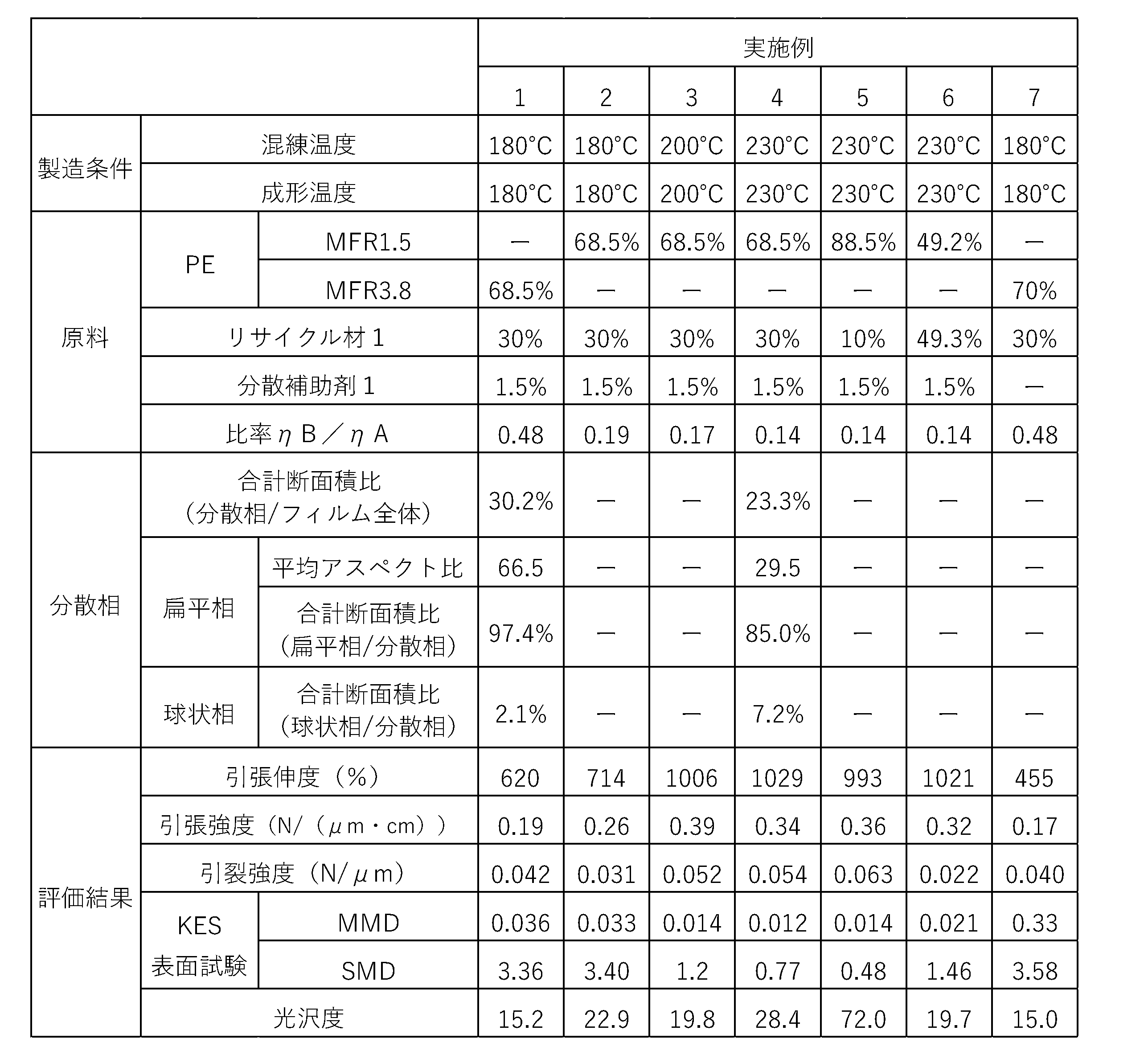
- Examples 1 to 7 films were produced using the production conditions and raw materials shown in Table 2. In all of Examples 1 to 7, a single screw extruder was used for kneading, and an inflation molding method was used for molding. In all of Examples 1 to 7, recycled material 1 was used as the second raw material. In all of the films according to Examples 1 to 7, the ratio ⁇ B/ ⁇ A of the viscosity ⁇ B of polypropylene (PP) to the viscosity ⁇ A of polyethylene (PE) fell within the range of the above embodiment.
- PP polypropylene
- PE polyethylene
- Figure 7 shows a TEM image of the MD cross section of the film of Example 4.
- the average aspect ratio of the flat phase determined from the TEM image shown in Figure 7 was 29.5, and the average aspect ratio of the spherical phase formed from polyurethane (PU) was 1.
- the average aspect ratio of the flat phase determined from the TEM image was 66.5, and the average aspect ratio of the spherical phase formed from polyurethane (PU) was 1.
- the total cross-sectional area ratio of the flat phase to the entire dispersed phase was 80% or more.
- Table 2 shows the evaluation results of the films according to Examples 1 to 7. All of the films according to Examples 1 to 7 had a significantly higher tensile elongation than the film according to the Comparative Example. Furthermore, the evaluation results of Examples 1 to 7 showed a tendency for the tensile elongation to be higher for films with a smaller ratio ⁇ B/ ⁇ A of the viscosity ⁇ B of polypropylene (PP) to the viscosity ⁇ A of polyethylene (PE). Furthermore, all of the films according to Examples 1 to 7 had lower MMD and SMD by KES surface testing than the film according to the Comparative Example, and it was found that a good feel was obtained. In addition, all of the films according to Examples 1 to 7 had a lower gloss than the film according to the Reference Example, and it was found that a matte visual texture was obtained.
- PP polypropylene
- PE polyethylene
- Example 8 to 10 films were produced using the production conditions and raw materials shown in Table 3.
- a single screw extruder was used for kneading, and an inflation molding method was used for molding.
- recycled material 1 was used as the second raw material.
- calcium carbonate was further used as the inorganic material constituting the inorganic material phase.
- titanium oxide was further used as the inorganic material constituting the inorganic material phase.
- the ratio ⁇ B/ ⁇ A of the viscosity ⁇ B of polypropylene (PP) to the viscosity ⁇ A of polyethylene (PE) fell within the range of the above embodiment.
- Table 3 shows the evaluation results of the films of Examples 8 to 10. All of the films of Examples 8 to 10 had a significantly higher tensile elongation than the film of the Comparative Example. In addition, all of the films of Examples 8 to 10 had lower MMD and SMD in the KES surface test than the film of the Comparative Example, indicating that they had a good feel to the touch. Furthermore, all of the films of Examples 8 to 10 had a lower gloss than the film of the Reference Example, indicating that they had a matte visual texture.
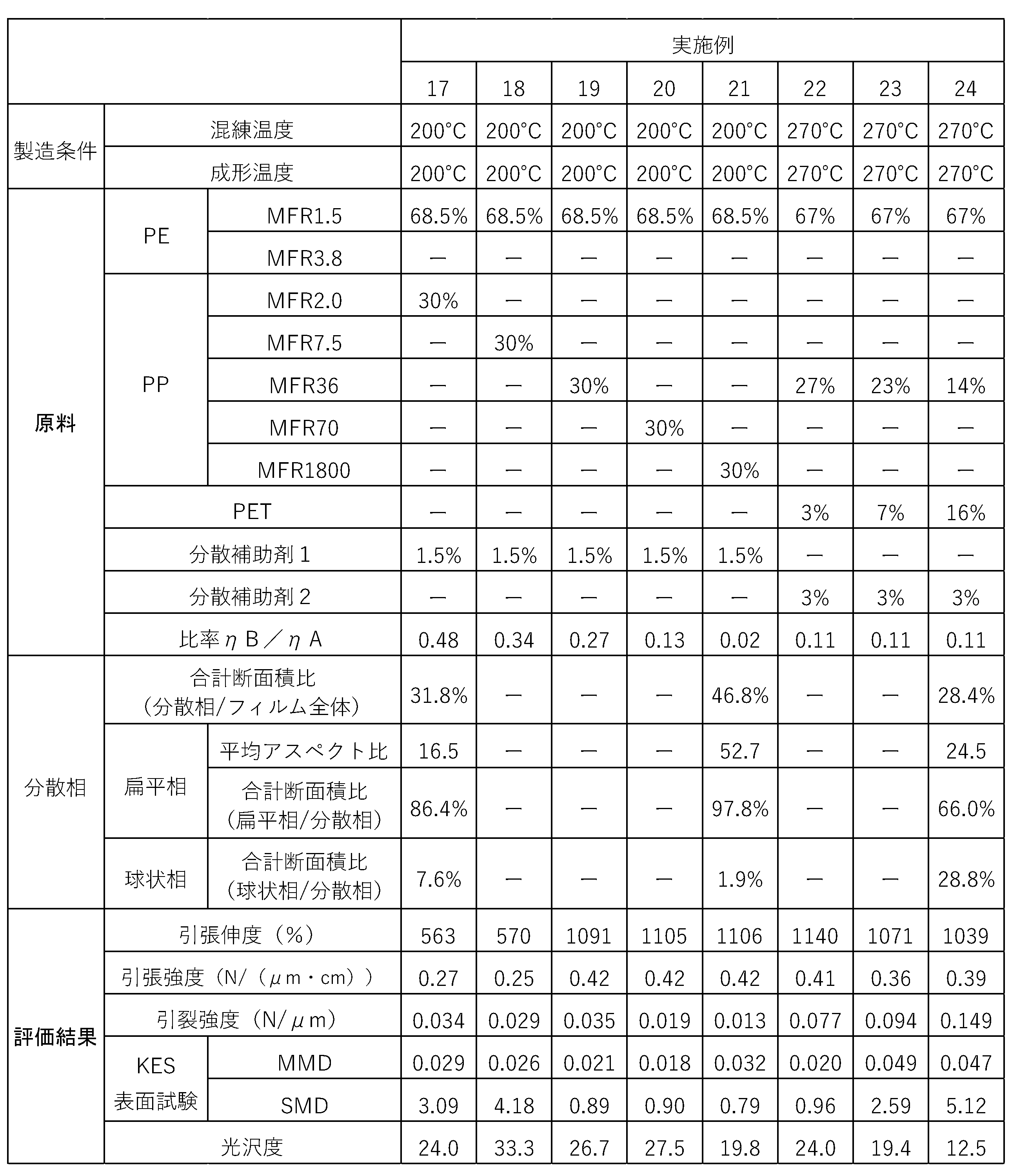
- Example 11 to 24 films were produced using the manufacturing conditions and raw materials shown in Tables 4 and 5.
- a single-screw extruder was used for kneading, and an inflation molding method was used for molding.
- virgin polypropylene (PP) material was used as the second raw material.
- the kneading temperature and molding temperature were 230°C.
- the kneading temperature and molding temperature were 200°C.
- PET polyethylene terephthalate
- the ratio ⁇ B/ ⁇ A of the viscosity ⁇ B of polypropylene (PP) to the viscosity ⁇ A of polyethylene (PE) was within the range of the above embodiment. In all of Examples 22 to 24, the ratio of the viscosity of polyethylene terephthalate (PET) to the viscosity ⁇ A of polyethylene (PE) at the molding temperature was 0.11.
- Figure 8 shows a TEM image of the MD cross section of the film of Example 24.
- the average aspect ratio of the flat phase determined from the TEM image shown in Figure 8 was 24.5, and the average aspect ratio of the spherical phase formed of polyethylene terephthalate (PET) was 2.
- PET polyethylene terephthalate
- the average aspect ratio of the flat phase determined from the TEM image was 16.5.
- the average aspect ratio of the flat phase determined from the TEM image was 52.7.
- the total cross-sectional area ratio of the flat phase to the entire dispersed phase was 60% or more.
- Tables 4 and 5 show the evaluation results of the films of Examples 11 to 24. All of the films of Examples 11 to 24 had a significantly higher tensile elongation than the film of the Comparative Example. Furthermore, when comparing the evaluation results of Examples 13 and 19 with those of Examples 22 to 24, it was found that the tear strength was significantly improved by using polyethylene terephthalate (PET). Furthermore, all of the films of Examples 11 to 24 had lower MMD and SMD in the KES surface test than the film of the Comparative Example, and were found to have a good feel to the touch. In addition, all of the films of Examples 11 to 24 had a lower gloss than the film of the Reference Example, and were found to have a matte visual texture.
- PET polyethylene terephthalate
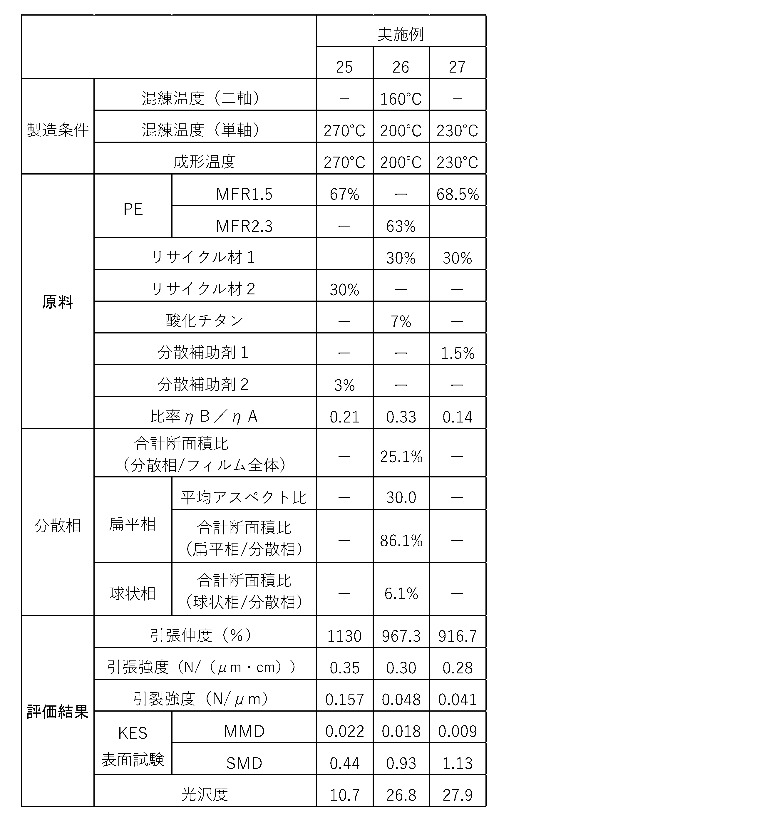
- Example 25 films were produced using the manufacturing conditions and raw materials shown in Table 6.
- a single screw extruder was used for kneading, and an inflation molding method was used for molding.
- recycled material 2 was used as the second raw material.
- Example 26 a single screw extruder and a twin screw extruder were used in combination for kneading, and an inflation molding method was used for molding. More specifically, in Example 26, kneading was performed using a twin screw extruder before kneading using a single screw extruder.
- recycled material 1 was used as the second raw material, and titanium oxide was used as the inorganic material constituting the inorganic material phase.
- Example 27 a single screw extruder was used for kneading, and a T-die molding method was used for molding. In Example 27, recycled material 1 was used as the second raw material. In all of the films according to Examples 25 to 27, the ratio ⁇ B/ ⁇ A of the viscosity ⁇ B of polypropylene (PP) to the viscosity ⁇ A of polyethylene (PE) was within the range of the above embodiment.
- PP polypropylene
- PE polyethylene
- the average aspect ratio of the flat phase determined from the TEM image in the same manner as above was 30.0, and the average aspect ratio of the spherical phase formed from polyurethane (PU) was 1.
- the total cross-sectional area ratio of the flat phase to the entire dispersed phase was 80% or more.
- Table 6 shows the evaluation results of the films of Examples 25 to 27. All of the films of Examples 25 to 27 had a significantly higher tensile elongation than the film of the Comparative Example. In addition, all of the films of Examples 25 to 27 had lower MMD and SMD in the KES surface test than the film of the Comparative Example, indicating that a good feel was obtained. Furthermore, all of the films of Examples 25 to 27 had a lower gloss than the film of the Reference Example, indicating that a matte visual texture was obtained.
- the present invention makes it possible to suppress the deterioration of quality caused by polypropylene in a film in which polypropylene is dispersed in polyethylene.
Landscapes
- Chemical & Material Sciences (AREA)
- Engineering & Computer Science (AREA)
- Manufacturing & Machinery (AREA)
- Materials Engineering (AREA)
- Health & Medical Sciences (AREA)
- Chemical Kinetics & Catalysis (AREA)
- Medicinal Chemistry (AREA)
- Polymers & Plastics (AREA)
- Organic Chemistry (AREA)
- Manufacture Of Macromolecular Shaped Articles (AREA)
- Compositions Of Macromolecular Compounds (AREA)
Abstract
Description
上記フィルムは、ポリエチレンを含むマトリックス相と、ポリプロピレンを含む分散相と、を含む。
上記分散相は少なくともMD方向に配向する扁平相を含み、上記扁平相の平均アスペクト比が15以上である。
上記フィルム成形の際の成形温度における上記第1原料の粘度ηAに対する上記成形温度における上記第2原料に含まれるポリプロピレンの粘度ηBの比率ηB/ηAが0.015以上1未満である。
本実施形態に係るフィルムは、マトリックス相と、分散相と、を有し、マトリックス相に分散相が分散した構成を有する。マトリックス相は、ポリエチレンを含む。分散相は、ポリプロピレンを含む扁平相を有する。
引張伸度(%)=100×A(mm)/20mm
引張強度(N/(μm・cm))=B(N)/0.5cm/C(μm)
以下、図2に沿って、本実施形態に係るフィルムの製造方法の一例について説明するが、本実施形態に係るフィルムの製造方法は図2に示す例に限定されない。図2に示すフィルムの製造方法は、原料準備工程(ステップS01)、混練工程(ステップS02)、及びフィルム成形工程(ステップS03)を含む。
ステップS01では、本実施形態に係るフィルムの原料を準備する。具体的に、ステップS01では、第1原料及び第2原料を準備する。第1原料は、マトリックス相を構成するポリエチレンのバージン材である。第2原料は、分散相の扁平相を構成するポリプロピレンを含むリサイクル材である。
ステップS02では、ステップS01で準備した第1原料及び第2原料を混練することで混練物を作製する。図3は、ステップS02で得られる混練物の断面を透過型電子顕微鏡で撮像したTEM画像である。図3に示す組織では、濃色のマトリックス相に淡色の分散相が分散している。
ステップS03では、ステップS02で作製した混練物を薄く延伸させることでフィルム状に成形する。第1原料の粘度ηAが、成形温度における粘度ηAに対する粘度ηBの比率ηB/ηAが0.015以上1未満となるように調整されていることで、混練物を延伸させる過程でポリプロピレンを主成分とする分散相が扁平相となる。
以上、本発明の実施形態について説明したが、本発明は上述の実施形態にのみ限定されるものではなく、本発明の要旨を逸脱しない範囲内において種々変更を加え得ることは勿論である。
<1>
マトリックス相に分散相が分散されたフィルムであって、
ポリエチレンを含むマトリックス相と、ポリプロピレンを含む分散相と、を含み、
前記分散相は少なくともMD方向に配向する扁平相を含み、前記扁平相の平均アスペクト比が15以上である
フィルム。
<2>
前記フィルムを透過型電子顕微鏡で撮像した画像における前記分散相の合計断面積に対する前記扁平相の合計断面積の比率が60%以上である
<1>に記載のフィルム。
<3>
前記分散相は、樹脂で構成され、アスペクト比が3以下の球状相を更に含む
<1>又は<2>に記載のフィルム。
<4>
前記球状相は、ポリエチレンテレフタラート、及びポリウレタンの少なくとも一方を含む
<3>に記載のフィルム。
<5>
前記分散相は、無機材料相を更に含む
<1>から<4>のいずれか1つに記載のフィルム。
<6>
前記フィルムを透過型電子顕微鏡で撮像した画像における前記フィルムの合計断面積に対するポリエチレンの合計断面積の比率が50%以上99%以下である
<1>から<5>のいずれか1つに記載のフィルム。
<7>
前記フィルムを透過型電子顕微鏡で撮像した画像における前記フィルムの合計断面積に対するポリプロピレンの合計断面積の比率が1%以上50%以下である
<1>から<6>のいずれか1つに記載のフィルム。
<8>
引張伸度が700%以上である
<1>から<7>のいずれか1つに記載のフィルム。
<9>
引張強度が0.23N/(μm・cm)以上である
<1>から<8>のいずれか1つに記載のフィルム。
<10>
引裂強度が0.015N/μm以上である
<1>から<9>のいずれか1つに記載のフィルム。
<11>
KES表面試験によるMMDが0.05以下である
<1>から<10>のいずれか1つに記載のフィルム。
<12>
KES表面試験によるSMDが3.0以下である
<1>から<11>のいずれか1つに記載のフィルム。
<13>
表面の光沢度が80以下である
<1>から<12>のいずれか1つに記載のフィルム。
<14>
表面の濡れ性が40mN/m以上である
<1>から<13>のいずれか1つに記載のフィルム。
<15>
吸収性物品に由来する廃棄物を原料の一部とする
<1>から<14>のいずれか1つに記載のフィルム。
<16>
マトリックス相に分散相が分散されたフィルムの製造方法であって、
ポリエチレンを含み、前記マトリックス相を構成する第1原料と、前記分散相を構成する成分としてポリプロピレンを含む第2原料と、を混錬した混練物をフィルム成形し、
前記フィルム成形の際の成形温度における前記第1原料の粘度ηAに対する前記成形温度における前記第2原料に含まれるポリプロピレンの粘度ηBの比率ηB/ηAが0.015以上1未満である
フィルムの製造方法。
<17>
前記第2原料は、吸収性物品に由来する廃棄物を含む
<16>に記載のフィルムの製造方法。
<18>
単軸押出機を用いて前記第1原料と前記第2原料とを混練する
<16>又は<17>に記載のフィルムの製造方法。
<19>
インフレーション成形法によって前記混練物をフィルム成形する
<16>から<18>のいずれか1つに記載のフィルムの製造方法。
<20>
前記第2原料は、前記分散相を構成する成分として、前記第1原料よりも融点が100℃以上高い熱可塑性樹脂、及び熱硬化性樹脂の少なくとも一方を更に含む
<16>から<19>のいずれか1つに記載のフィルムの製造方法。
<21>
フィルム成形後のフィルムの表面にコロナ処理を施す
<16>から<20>のいずれか1つに記載のフィルムの製造方法。
<22>
前記成形温度が200℃以上300℃以下である
<16>から<21>のいずれか1つに記載のフィルムの製造方法。
<23>
前記扁平相は、MD方向及びTD方向に配向している
<1>から<15>のいずれか1つに記載のフィルム。
<24>
前記フィルムを透過型電子顕微鏡で撮像した画像における前記フィルムの合計断面積に対するポリエチレンの合計断面積の比率が60%以上である
<1>から<15>、及び<23>のいずれか1つに記載のフィルム。
<25>
前記フィルムを透過型電子顕微鏡で撮像した画像における前記フィルムの合計断面積に対するポリプロピレンの合計断面積の比率が40%以下である
<1>から<15>、<23>、及び<24>のいずれか1つに記載のフィルム。
<26>
ポリエチレンの含有量が50質量%以上である
<1>から<15>、及び<23>から<25>のいずれか1つに記載のフィルム。
<27>
ポリプロピレンの含有量が50質量%以下である
<1>から<15>、及び<23>から<26>のいずれか1つに記載のフィルム。
<28>
前記フィルムを透過型電子顕微鏡で撮像した画像における前記フィルムの合計断面積に対するポリエチレンの合計断面積の比率が99%以下である
<1>から<15>、及び<23>から<27>のいずれか1つに記載のフィルム。
<29>
前記フィルムを透過型電子顕微鏡で撮像した画像における前記フィルムの合計断面積に対するポリプロピレンの合計断面積の比率が1%以上である
<1>から<15>、及び<23>から<27>のいずれか1つに記載のフィルム。
<30>
ポリエチレンの含有量が99質量%以下である
<1>から<15>、及び<23>から<29>のいずれか1つに記載のフィルム。
<31>
ポリプロピレンの含有量が1質量%以上である
<1>から<15>、及び<23>から<30>のいずれか1つに記載のフィルム。
<32>
球状相を構成する樹脂の含有量が0.05質量%以上20質量%以下である
<1>から<15>、及び<23>から<31>のいずれか1つに記載のフィルム。
<33>
球状相の平均粒径が1nm以上2μm以下である
<1>から<15>、及び<23>から<32>のいずれか1つに記載のフィルム。
<34>
分散相の球状相として、スチレン系エラストマー、エチレン・α-オレフィン共重合体(エチレンがコモノマーとして存在しているものを含む)、極性基が導入されたオレフィン系樹脂、及び極性基が導入されたスチレン系樹脂の少なくとも1つを含む相を含む
<1>から<15>、及び<23>から<33>のいずれか1つに記載のフィルム。
<35>
スチレン系エラストマー、エチレン・α-オレフィン共重合体(エチレンがコモノマーとして存在しているものを含む)、極性基が導入されたオレフィン系樹脂、及び極性基が導入されたスチレン系樹脂の少なくとも1つを含む前記相を構成する樹脂の含有量が0.5質量%以上15質量%以下である
<34>に記載のフィルム。
<36>
吸収性物品に由来する廃棄物を原料の一部とし、
吸収性物品に由来する廃棄物を、前記分散相における少なくとも前記扁平相の原料とする
<1>から<15>、及び<23>から<35>のいずれか1つに記載のフィルム。
<37>
前記フィルムは、パッケージフィルムとして利用される
<1>から<15>、及び<23>から<36>のいずれか1つに記載のフィルム。
<38>
前記フィルムの表面の光沢度が80以下である
<1>から<15>、及び<23>から<37>のいずれか1つに記載のフィルム。
以下、上記実施形態の実施例及び比較例について説明するが、本発明は以下の実施例の構成に限定されない。
第1原料を構成するポリエチレン(PE)のバージン材としては、メルトフローレート(MFR)が相互に異なる以下の直鎖状低密度ポリエチレン(LLDPE)の製品を用いた。なお、下記の表1~5では、ポリエチレン(PE)の各製品を区別するために単位無しのMFRを示している。また、ポリエチレンのMFRとしては、各製品のメーカーカタログ値(190℃、荷重2.16kg)を示している。
・エボリューSP2510(プライムポリマー社製、MFR:1.5g/10min)
・エボリューSP2020(プライムポリマー社製、MFR:2.3g/10min)
・エボリューSP2540(プライムポリマー社製、MFR:3.8g/10min)
・UJ317(日本ポリエチレン社製、MFR:6.0g/10min)
・ウルトゼックス2520F(プライムポリマー社製、MFR:2.2g/10min)
リサイクル材1は、花王株式会社製のベビー用おむつであるメリーズ(登録商標)パンツ さらさらエアスルーLサイズ(2022年製)の製造工程において股繰り部分をカットした際に発生する端材を単軸押出機にてペレット化したものである。リサイクル材1の平均組成としては、ポリプロピレン(PP)の含有量が84質量%であり、スチレン系エラストマーの含有量が4質量%であり、ポリウレタン(PU)の含有量が2質量%である。
リサイクル材2は、花王株式会社製の生理用ナプキンであるロリエ(登録商標)しあわせ素肌 特に多い昼用25cm 羽つき(2022年製)の製造工程においてラウンド部分をカットした際に発生する端材を単軸押出機にてペレット化したものである。リサイクル材2の平均組成としては、ポリエチレン(PE)の含有量が30質量%であり、ポリプロピレン(PP)の含有量が35質量%であり、ポリエチレンテレフタラート(PET)の含有量が2質量%であり、炭酸カルシウムの含有量が28質量%である。リサイクル材の原料構成は、発生元である製品構成によって変わりうるが、第1原料へのリサイクル材の配合率は、フィルム中のPPが20~50質量%、フィルム中のPETが0~5質量%、フィルム中のPUが0~5質量%、前記樹脂の合計が50質量%以下の範囲に管理することが、フィルムの品質、バージン材削減の観点から好ましい。
・F300SP(プライムポリマー社製、MFR:2g/10min)
・PM600A(サンアロマー社製、MFR:7.5g/10min)
・3155E3(エクソンモービル社製、MFR:36g/10min)
・PLB00A(サンアロマー社製、MFR:70g/10min)
・MF650Y(LyondellBasel社製、MFR:1800g/10min)
分散補助剤としては、分散補助剤1,2を用いた。分散補助剤1としては、エチレン―プロピレン共重合体であるVistamaxx Performance Polymer 7050BF(エクソンモービル社製)を用いた。分散補助剤2としては、無水マレイン酸変性水添スチレン系熱可塑性エラストマーであるタフテックM C5025(旭化成社製)を用いた。
無機材料相を構成する無機材料としては、炭酸カルシウム及び酸化チタンを用いた。具体的に、炭酸カルシウムとしては、花王株式会社製のベビー用おむつであるメリーズ用透湿フィルムの生産ロスの再ペレット品(ウルトゼックス2520F(プライムポリマー社製、MFR:2.2g/10min)と炭酸カルシウムの配合品)に含まれる炭酸カルシウムを用いた。酸化チタンとしては、酸化チタンマスターであるTET1TA538WHT-FD(トーヨーカラー社製)を用いた
なお、下記の表1~5では、各原料の含有量を質量比率で示している。
上記の原料で作製したフィルムのうちの一部について、分散相の分析のために、TEM画像を用いた評価を行った。具体的に、各フィルムについて、フィルム全体に占める分散相の合計断面積比(分散相/フィルム全体)を求めた。また、各フィルムについて、扁平相の平均アスペクト比、及び分散相全体に占める扁平相の合計断面積比(扁平相/分散相)を求めた。更に、各フィルムついて、分散相全体に占める球状相の合計断面積比(球状相/分散相)を求めた。
引張伸度及び引張強度の測定方法、引裂強度の測定方法、KES表面試験の方法、及び光沢度の測定方法は、上記実施形態で説明したとおりである。
参考例及び比較例として、表1に示す製造条件及び原料を用いてフィルムを作製した。参考例及び比較例ではいずれも、混練に単軸押出機を用い、成形にインフレーション成形法を用いた。
参考例に係るフィルムは、ポリエチレン(PE)のみで構成される点で上記実施形態の構成とは異なり、一般的なフィルムとして良好な品質が得られる構成を有する。つまり、比較例1に係るフィルムは、各実施例に係るフィルムを評価する上での良好な品質の基準となる。
比較例に係るフィルムは、ポリエチレン(PE)の粘度ηAに対するポリプロピレン(PP)の粘度ηBの比率ηB/ηAが1以上である点で上記実施形態の構成と異なる。図6は、比較例に係るフィルムのMD断面を撮像したTEM画像を示している。比較例に係るフィルムでは、図6に示すTEM画像から求めた扁平相の平均アスペクト比が12.3であり、上記実施形態よりも小さかった。

実施例1~7として、表2に示す製造条件及び原料を用いてフィルムを作製した。実施例1~7ではいずれも、混練に単軸押出機を用い、成形にインフレーション成形法を用いた。実施例1~7ではいずれも、第2原料としてリサイクル材1を用いた。実施例1~7に係るフィルムではいずれも、ポリエチレン(PE)の粘度ηAに対するポリプロピレン(PP)の粘度ηBの比率ηB/ηAが上記実施形態の範囲内となった。
実施例8~10として、表3に示す製造条件及び原料を用いてフィルムを作製した。実施例8~10ではいずれも、混練に単軸押出機を用い、成形にインフレーション成形法を用いた。実施例8~10ではいずれも、第2原料としてリサイクル材1を用いた。実施例8,9では更に、無機材料相を構成する無機材料として炭酸カルシウムを用いた。実施例10では更に、無機材料相を構成する無機材料として酸化チタンを用いた。実施例8~10に係るフィルムではいずれも、ポリエチレン(PE)の粘度ηAに対するポリプロピレン(PP)の粘度ηBの比率ηB/ηAが上記実施形態の範囲内となった。

実施例11~24として、表4,5に示す製造条件及び原料を用いてフィルムを作製した。実施例11~24ではいずれも、混練に単軸押出機を用い、成形にインフレーション成形法を用いた。実施例11~24ではいずれも、第2原料としてポリプロピレン(PP)のバージン材を用いた。実施例11~16では、混練温度及び成形温度を230℃とした。実施例17~21では、混練温度及び成形温度を200℃とした。実施例22~24では更に、球状相を構成する樹脂としてポリエチレンテレフタラート(PET)を用い、混練温度及び成形温度を270℃とした。実施例11~24に係るフィルムではいずれも、ポリエチレン(PE)の粘度ηAに対するポリプロピレン(PP)の粘度ηBの比率ηB/ηAが上記実施形態の範囲内となった。なお、実施例22~24ではいずれも、成形温度におけるポリエチレン(PE)の粘度ηAに対するポリエチレンテレフタラート(PET)の粘度の比率が0.11であった。

実施例25~27として、表6に示す製造条件及び原料を用いてフィルムを作製した。実施例25では、混練に単軸押出機を用い、成形にインフレーション成形法を用いた。また、実施例25では、第2原料としてリサイクル材2を用いた。実施例26では、混練に単軸押出機及び二軸押出機を併用し、成形にインフレーション成形法を用いた。より詳細に、実施例26では、単軸押出機による混練の前に二軸押出機による混練を行った。また、実施例26では、第2原料としてリサイクル材1を用い、無機材料相を構成する無機材料として酸化チタンを用いた。実施例27では、混練に単軸押出機を用い、成形にTダイ成形法を用いた。また、実施例27では、第2原料としてリサイクル材1を用いた。実施例25~27に係るフィルムではいずれも、ポリエチレン(PE)の粘度ηAに対するポリプロピレン(PP)の粘度ηBの比率ηB/ηAが上記実施形態の範囲内となった。
Claims (22)
- マトリックス相に分散相が分散されたフィルムであって、
ポリエチレンを含むマトリックス相と、ポリプロピレンを含む分散相と、を含み、
前記分散相は少なくともMD方向に配向する扁平相を含み、前記扁平相の平均アスペクト比が15以上である
フィルム。 - 前記フィルムを透過型電子顕微鏡で撮像した画像における前記分散相の合計断面積に対する前記扁平相の合計断面積の比率が60%以上である
請求項1に記載のフィルム。 - 前記分散相は、樹脂で構成され、アスペクト比が3以下の球状相を更に含む
請求項1又は2に記載のフィルム。 - 前記球状相は、ポリエチレンテレフタラート、及びポリウレタンの少なくとも一方を含む
請求項3に記載のフィルム。 - 前記分散相は、無機材料相を更に含む
請求項1から4のいずれか1項に記載のフィルム。 - 前記フィルムを透過型電子顕微鏡で撮像した画像における前記フィルムの合計断面積に対するポリエチレンの合計断面積の比率が50%以上99%以下である
請求項1から5のいずれか1項に記載のフィルム。 - 前記フィルムを透過型電子顕微鏡で撮像した画像における前記フィルムの合計断面積に対するポリプロピレンの合計断面積の比率が1%以上50%以下である
請求項1から6のいずれか1項に記載のフィルム。 - 引張伸度が700%以上である
請求項1から7のいずれか1項に記載のフィルム。 - 引張強度が0.23N/(μm・cm)以上である
請求項1から8のいずれか1項に記載のフィルム。 - 引裂強度が0.015N/μm以上である
請求項1から9のいずれか1項に記載のフィルム。 - KES表面試験によるMMDが0.05以下である
請求項1から10のいずれか1項に記載のフィルム。 - KES表面試験によるSMDが3.0以下である
請求項1から11のいずれか1項に記載のフィルム。 - 表面の光沢度が80以下である
請求項1から12のいずれか1項に記載のフィルム。 - 表面の濡れ性が40mN/m以上である
請求項1から13のいずれか1項に記載のフィルム。 - 吸収性物品に由来する廃棄物を原料の一部とする
請求項1から14のいずれか1項に記載のフィルム。 - マトリックス相に分散相が分散されたフィルムの製造方法であって、
ポリエチレンを含み、前記マトリックス相を構成する第1原料と、前記分散相を構成する成分としてポリプロピレンを含む第2原料と、を混錬した混練物をフィルム成形し、
前記フィルム成形の際の成形温度における前記第1原料の粘度ηAに対する前記成形温度における前記第2原料に含まれるポリプロピレンの粘度ηBの比率ηB/ηAが0.015以上1未満である
フィルムの製造方法。 - 前記第2原料は、吸収性物品に由来する廃棄物を含む
請求項16に記載のフィルムの製造方法。 - 単軸押出機を用いて前記第1原料と前記第2原料とを混練する
請求項16又は17に記載のフィルムの製造方法。 - インフレーション成形法によって前記混練物をフィルム成形する
請求項16から18のいずれか1項に記載のフィルムの製造方法。 - 前記第2原料は、前記分散相を構成する成分として、前記第1原料よりも融点が100℃以上高い熱可塑性樹脂、及び熱硬化性樹脂の少なくとも一方を更に含む
請求項16から19のいずれか1項に記載のフィルムの製造方法。 - フィルム成形後のフィルムの表面にコロナ処理を施す
請求項16から20のいずれか1項に記載のフィルムの製造方法。 - 前記成形温度が200℃以上300℃以下である
請求項16から21のいずれか1項に記載のフィルムの製造方法。
Priority Applications (4)
| Application Number | Priority Date | Filing Date | Title |
|---|---|---|---|
| PCT/JP2023/024865 WO2025009082A1 (ja) | 2023-07-05 | 2023-07-05 | フィルム |
| CN202380097972.4A CN121127526A (zh) | 2023-07-05 | 2023-07-05 | 膜 |
| EP23944334.4A EP4741447A1 (en) | 2023-07-05 | 2023-07-05 | Film |
| JP2024570449A JP7618901B1 (ja) | 2023-07-05 | 2023-07-05 | フィルム |
Applications Claiming Priority (1)
| Application Number | Priority Date | Filing Date | Title |
|---|---|---|---|
| PCT/JP2023/024865 WO2025009082A1 (ja) | 2023-07-05 | 2023-07-05 | フィルム |
Publications (1)
| Publication Number | Publication Date |
|---|---|
| WO2025009082A1 true WO2025009082A1 (ja) | 2025-01-09 |
Family
ID=94171261
Family Applications (1)
| Application Number | Title | Priority Date | Filing Date |
|---|---|---|---|
| PCT/JP2023/024865 Ceased WO2025009082A1 (ja) | 2023-07-05 | 2023-07-05 | フィルム |
Country Status (4)
| Country | Link |
|---|---|
| EP (1) | EP4741447A1 (ja) |
| JP (1) | JP7618901B1 (ja) |
| CN (1) | CN121127526A (ja) |
| WO (1) | WO2025009082A1 (ja) |
Citations (7)
| Publication number | Priority date | Publication date | Assignee | Title |
|---|---|---|---|---|
| JPH09141791A (ja) * | 1995-11-24 | 1997-06-03 | Daicel Chem Ind Ltd | 多層フィルムと包装体 |
| JP2000063533A (ja) * | 1998-08-26 | 2000-02-29 | Chisso Corp | ポリプロピレン系成形品 |
| JP2002052532A (ja) | 2000-08-09 | 2002-02-19 | Kayaba Ind Co Ltd | ポリエチレン製シートのリサイクル方法およびリサイクルシステム |
| JP2004182957A (ja) | 2001-12-11 | 2004-07-02 | Osaka Gas Co Ltd | プラスチック材料、再生プラスチック材料及び成形体 |
| JP2008008138A (ja) * | 2006-05-29 | 2008-01-17 | Toray Ind Inc | 床材およびその製造方法 |
| JP2011046190A (ja) * | 2009-07-31 | 2011-03-10 | Bando Chemical Industries Ltd | 化粧用フィルム |
| JP2014234481A (ja) * | 2013-06-04 | 2014-12-15 | 株式会社ブリヂストン | 積層体形成用シート製造用組成物、その製造方法、及び積層体形成用シート |
-
2023
- 2023-07-05 JP JP2024570449A patent/JP7618901B1/ja active Active
- 2023-07-05 WO PCT/JP2023/024865 patent/WO2025009082A1/ja not_active Ceased
- 2023-07-05 CN CN202380097972.4A patent/CN121127526A/zh active Pending
- 2023-07-05 EP EP23944334.4A patent/EP4741447A1/en active Pending
Patent Citations (7)
| Publication number | Priority date | Publication date | Assignee | Title |
|---|---|---|---|---|
| JPH09141791A (ja) * | 1995-11-24 | 1997-06-03 | Daicel Chem Ind Ltd | 多層フィルムと包装体 |
| JP2000063533A (ja) * | 1998-08-26 | 2000-02-29 | Chisso Corp | ポリプロピレン系成形品 |
| JP2002052532A (ja) | 2000-08-09 | 2002-02-19 | Kayaba Ind Co Ltd | ポリエチレン製シートのリサイクル方法およびリサイクルシステム |
| JP2004182957A (ja) | 2001-12-11 | 2004-07-02 | Osaka Gas Co Ltd | プラスチック材料、再生プラスチック材料及び成形体 |
| JP2008008138A (ja) * | 2006-05-29 | 2008-01-17 | Toray Ind Inc | 床材およびその製造方法 |
| JP2011046190A (ja) * | 2009-07-31 | 2011-03-10 | Bando Chemical Industries Ltd | 化粧用フィルム |
| JP2014234481A (ja) * | 2013-06-04 | 2014-12-15 | 株式会社ブリヂストン | 積層体形成用シート製造用組成物、その製造方法、及び積層体形成用シート |
Also Published As
| Publication number | Publication date |
|---|---|
| EP4741447A1 (en) | 2026-05-13 |
| JPWO2025009082A1 (ja) | 2025-01-09 |
| CN121127526A (zh) | 2025-12-12 |
| JP7618901B1 (ja) | 2025-01-21 |
Similar Documents
| Publication | Publication Date | Title |
|---|---|---|
| EP2406313B2 (en) | Machine direction oriented film for labels | |
| JP7548346B2 (ja) | 二軸配向ポリプロピレン系フィルムの製造方法 | |
| Shirai et al. | Thermoplastic starch/polyester films: Effects of extrusion process and poly (lactic acid) addition | |
| EP1692217B1 (en) | Void-containing polyester shrink film | |
| KR20240058955A (ko) | 2축 배향 폴리프로필렌 필름 | |
| US20050100729A1 (en) | Peelable polyester film having improved oxygen barrier, process for its production and its use | |
| JP7823102B2 (ja) | 包装用の二軸延伸ポリプロピレンフィルム | |
| CN114728509B (zh) | 可回收包装材料及其制备方法 | |
| KR100435942B1 (ko) | 폴리프로필렌계 미연신 성형체 | |
| JP7618901B1 (ja) | フィルム | |
| JP4890064B2 (ja) | 二軸延伸ポリプロピレン系フィルムおよび包装袋 | |
| EP4209331A1 (de) | Biaxial-orientierte polyethylenfolien für das thermoformen, verfahren zu ihrer herstellung, ihre verwendung, ein verfahren zum thermoformen und dessen produkte | |
| WO2013099698A1 (ja) | 易裂性ラミネートフィルムおよび易裂性包装袋 | |
| WO2023195382A1 (ja) | 延伸フィルム | |
| EP4482685A1 (de) | Maschinenlaufrichtungorientierte folienverpackung mit hohlräumen | |
| US7915342B2 (en) | Breathable films | |
| Santi et al. | Films of post-consumer polypropylene composites for the support layer in synthetic paper | |
| JP2025023627A (ja) | 二軸延伸ポリエチレンフィルム及びラミネートフィルム並びに包装体 | |
| JP7854382B2 (ja) | 樹脂組成物及びその成形体 | |
| KR20070053776A (ko) | 포장 용도를 위한 불투명 필름 | |
| Duyğun et al. | Analysis of Mechanical Properties of EVOH/LDPE Films Produced with Waste EVOH and LDPE | |
| EP4512615A1 (en) | Polymer molded body comprising base part and surface layer part | |
| TW202547913A (zh) | 用於雙軸定向不透明薄膜應用之再生聚丙烯組成物 | |
| US20210139680A1 (en) | Film with selective opacity contrast | |
| JP2026036370A (ja) | 真空成形用シート及び真空成形部材の製造方法 |
Legal Events
| Date | Code | Title | Description |
|---|---|---|---|
| WWE | Wipo information: entry into national phase |
Ref document number: 2024570449 Country of ref document: JP |
|
| 121 | Ep: the epo has been informed by wipo that ep was designated in this application |
Ref document number: 23944334 Country of ref document: EP Kind code of ref document: A1 |
|
| WWE | Wipo information: entry into national phase |
Ref document number: 202517125202 Country of ref document: IN |
|
| WWP | Wipo information: published in national office |
Ref document number: 202517125202 Country of ref document: IN |
|
| WWE | Wipo information: entry into national phase |
Ref document number: 2023944334 Country of ref document: EP |
|
| NENP | Non-entry into the national phase |
Ref country code: DE |
|
| ENP | Entry into the national phase |
Ref document number: 2023944334 Country of ref document: EP Effective date: 20260205 |
|
| WWP | Wipo information: published in national office |
Ref document number: 2023944334 Country of ref document: EP |