WO2025005252A1 - 車両用灯具 - Google Patents
車両用灯具 Download PDFInfo
- Publication number
- WO2025005252A1 WO2025005252A1 PCT/JP2024/023522 JP2024023522W WO2025005252A1 WO 2025005252 A1 WO2025005252 A1 WO 2025005252A1 JP 2024023522 W JP2024023522 W JP 2024023522W WO 2025005252 A1 WO2025005252 A1 WO 2025005252A1
- Authority
- WO
- WIPO (PCT)
- Prior art keywords
- light
- lens
- panel
- front side
- lens portion
- Prior art date
- Legal status (The legal status is an assumption and is not a legal conclusion. Google has not performed a legal analysis and makes no representation as to the accuracy of the status listed.)
- Ceased
Links
Images






Classifications
-
- F—MECHANICAL ENGINEERING; LIGHTING; HEATING; WEAPONS; BLASTING
- F21—LIGHTING
- F21S—NON-PORTABLE LIGHTING DEVICES; SYSTEMS THEREOF; VEHICLE LIGHTING DEVICES SPECIALLY ADAPTED FOR VEHICLE EXTERIORS
- F21S43/00—Signalling devices specially adapted for vehicle exteriors, e.g. brake lamps, direction indicator lights or reversing lights
- F21S43/20—Signalling devices specially adapted for vehicle exteriors, e.g. brake lamps, direction indicator lights or reversing lights characterised by refractors, transparent cover plates, light guides or filters
-
- F—MECHANICAL ENGINEERING; LIGHTING; HEATING; WEAPONS; BLASTING
- F21—LIGHTING
- F21S—NON-PORTABLE LIGHTING DEVICES; SYSTEMS THEREOF; VEHICLE LIGHTING DEVICES SPECIALLY ADAPTED FOR VEHICLE EXTERIORS
- F21S43/00—Signalling devices specially adapted for vehicle exteriors, e.g. brake lamps, direction indicator lights or reversing lights
- F21S43/20—Signalling devices specially adapted for vehicle exteriors, e.g. brake lamps, direction indicator lights or reversing lights characterised by refractors, transparent cover plates, light guides or filters
- F21S43/235—Light guides
- F21S43/242—Light guides characterised by the emission area
-
- F—MECHANICAL ENGINEERING; LIGHTING; HEATING; WEAPONS; BLASTING
- F21—LIGHTING
- F21S—NON-PORTABLE LIGHTING DEVICES; SYSTEMS THEREOF; VEHICLE LIGHTING DEVICES SPECIALLY ADAPTED FOR VEHICLE EXTERIORS
- F21S43/00—Signalling devices specially adapted for vehicle exteriors, e.g. brake lamps, direction indicator lights or reversing lights
- F21S43/20—Signalling devices specially adapted for vehicle exteriors, e.g. brake lamps, direction indicator lights or reversing lights characterised by refractors, transparent cover plates, light guides or filters
- F21S43/27—Attachment thereof
-
- F—MECHANICAL ENGINEERING; LIGHTING; HEATING; WEAPONS; BLASTING
- F21—LIGHTING
- F21S—NON-PORTABLE LIGHTING DEVICES; SYSTEMS THEREOF; VEHICLE LIGHTING DEVICES SPECIALLY ADAPTED FOR VEHICLE EXTERIORS
- F21S43/00—Signalling devices specially adapted for vehicle exteriors, e.g. brake lamps, direction indicator lights or reversing lights
- F21S43/30—Signalling devices specially adapted for vehicle exteriors, e.g. brake lamps, direction indicator lights or reversing lights characterised by reflectors
- F21S43/31—Optical layout thereof
-
- F—MECHANICAL ENGINEERING; LIGHTING; HEATING; WEAPONS; BLASTING
- F21—LIGHTING
- F21S—NON-PORTABLE LIGHTING DEVICES; SYSTEMS THEREOF; VEHICLE LIGHTING DEVICES SPECIALLY ADAPTED FOR VEHICLE EXTERIORS
- F21S43/00—Signalling devices specially adapted for vehicle exteriors, e.g. brake lamps, direction indicator lights or reversing lights
- F21S43/50—Signalling devices specially adapted for vehicle exteriors, e.g. brake lamps, direction indicator lights or reversing lights characterised by aesthetic components not otherwise provided for, e.g. decorative trim, partition walls or covers
-
- F—MECHANICAL ENGINEERING; LIGHTING; HEATING; WEAPONS; BLASTING
- F21—LIGHTING
- F21V—FUNCTIONAL FEATURES OR DETAILS OF LIGHTING DEVICES OR SYSTEMS THEREOF; STRUCTURAL COMBINATIONS OF LIGHTING DEVICES WITH OTHER ARTICLES, NOT OTHERWISE PROVIDED FOR
- F21V3/00—Globes; Bowls; Cover glasses
- F21V3/04—Globes; Bowls; Cover glasses characterised by materials, surface treatments or coatings
- F21V3/10—Globes; Bowls; Cover glasses characterised by materials, surface treatments or coatings characterised by coatings
-
- F—MECHANICAL ENGINEERING; LIGHTING; HEATING; WEAPONS; BLASTING
- F21—LIGHTING
- F21V—FUNCTIONAL FEATURES OR DETAILS OF LIGHTING DEVICES OR SYSTEMS THEREOF; STRUCTURAL COMBINATIONS OF LIGHTING DEVICES WITH OTHER ARTICLES, NOT OTHERWISE PROVIDED FOR
- F21V5/00—Refractors for light sources
-
- F—MECHANICAL ENGINEERING; LIGHTING; HEATING; WEAPONS; BLASTING
- F21—LIGHTING
- F21V—FUNCTIONAL FEATURES OR DETAILS OF LIGHTING DEVICES OR SYSTEMS THEREOF; STRUCTURAL COMBINATIONS OF LIGHTING DEVICES WITH OTHER ARTICLES, NOT OTHERWISE PROVIDED FOR
- F21V5/00—Refractors for light sources
- F21V5/04—Refractors for light sources of lens shape
-
- F—MECHANICAL ENGINEERING; LIGHTING; HEATING; WEAPONS; BLASTING
- F21—LIGHTING
- F21V—FUNCTIONAL FEATURES OR DETAILS OF LIGHTING DEVICES OR SYSTEMS THEREOF; STRUCTURAL COMBINATIONS OF LIGHTING DEVICES WITH OTHER ARTICLES, NOT OTHERWISE PROVIDED FOR
- F21V7/00—Reflectors for light sources
- F21V7/22—Reflectors for light sources characterised by materials, surface treatments or coatings, e.g. dichroic reflectors
- F21V7/28—Reflectors for light sources characterised by materials, surface treatments or coatings, e.g. dichroic reflectors characterised by coatings
-
- F—MECHANICAL ENGINEERING; LIGHTING; HEATING; WEAPONS; BLASTING
- F21—LIGHTING
- F21W—INDEXING SCHEME ASSOCIATED WITH SUBCLASSES F21K, F21L, F21S and F21V, RELATING TO USES OR APPLICATIONS OF LIGHTING DEVICES OR SYSTEMS
- F21W2103/00—Exterior vehicle lighting devices for signalling purposes
- F21W2103/20—Direction indicator lights
-
- F—MECHANICAL ENGINEERING; LIGHTING; HEATING; WEAPONS; BLASTING
- F21—LIGHTING
- F21W—INDEXING SCHEME ASSOCIATED WITH SUBCLASSES F21K, F21L, F21S and F21V, RELATING TO USES OR APPLICATIONS OF LIGHTING DEVICES OR SYSTEMS
- F21W2103/00—Exterior vehicle lighting devices for signalling purposes
- F21W2103/35—Brake lights
-
- F—MECHANICAL ENGINEERING; LIGHTING; HEATING; WEAPONS; BLASTING
- F21—LIGHTING
- F21Y—INDEXING SCHEME ASSOCIATED WITH SUBCLASSES F21K, F21L, F21S and F21V, RELATING TO THE FORM OR THE KIND OF THE LIGHT SOURCES OR OF THE COLOUR OF THE LIGHT EMITTED
- F21Y2115/00—Light-generating elements of semiconductor light sources
- F21Y2115/10—Light-emitting diodes [LED]
Definitions
- the present invention relates to a vehicle lamp.
- a vehicle lamp having a lens panel that emits light from a light source to the front side is known (see, for example, Patent Document 1).
- the present invention was made in consideration of the above, and aims to provide a vehicle lamp that can achieve a three-dimensional light emission state with a sense of depth.
- the vehicle lamp according to the present invention comprises a light source unit having a light source and emitting light from the light source to the front side, a lens panel arranged on the front side of the light source unit and having a lens section with a concave lens section recessed on the back side and a convex lens section protruding to the front side, emitting light from the light source unit to the front side from the emission surface of the lens section, and an outer lens arranged on the front side of the lens panel and emitting light emitted from the lens panel to the front side, and a light transmission pattern having an opening having a shape corresponding to the shape of the lens section is formed on the surface on the front side of the lens panel.
- the present invention provides a vehicle lamp that can achieve a three-dimensional light emission state with a sense of depth.
- FIG. 1 is a diagram showing an example of a rear part of a vehicle according to this embodiment.
- FIG. 2 is a diagram showing an example of a vehicle lamp according to the present embodiment.
- FIG. 3 is a diagram showing an example of a vehicle lamp according to the present embodiment.
- FIG. 4 is a diagram showing an example of a vehicle lamp according to this embodiment.
- FIG. 5 is a diagram showing an example of a vehicle lamp according to this embodiment.
- FIG. 6 is a diagram showing an example of a vehicle lamp according to this embodiment.
- FIG. 7 is a diagram showing an example of a vehicle lamp according to this embodiment.
- FIG. 8 is a perspective view showing an example of a lens panel according to the present embodiment.
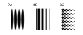
- FIG. 9 is a diagram showing an example of the shape of a light reflecting pattern provided on the lens panel according to this embodiment.
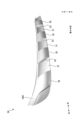
- FIG. 10 is a perspective view showing an example of the outer shape of the lens panel according to this embodiment.
- FIG. 11 is a perspective view showing an example of the outer shape of the lens panel according to this embodiment.
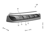
- FIG. 12 is a perspective view showing an example of the overall configuration of a vehicle lamp.
- FIG. 13 is a perspective view showing an example of the overall configuration of a vehicle lamp.
- FIG. 14 is a perspective view showing an example of the overall configuration of a vehicle lamp.
- FIG. 15 is a perspective view showing an example of the overall configuration of a vehicle lamp.
- FIG. 16 is a perspective view showing an example of the overall configuration of a vehicle lamp.
- the front and rear directions are the directions when the device is mounted on a vehicle (mounted on a vehicle).
- the front is the front direction (front side) and the rear is the rear direction (rear side).
- the rear is the front direction (front side) and the front is the rear direction (rear side).
- the outside of the vehicle is the front direction (front side) and the inside of the vehicle is the rear direction (rear side).
- FIG. 1 is a diagram showing an example of the rear of a vehicle 1 according to this embodiment.
- the vehicle 1 includes a vehicle body 2, a running device 3, and a vehicle lamp 100.
- the vehicle body 2 has a driver's cab in which a driver sits.
- the vehicle body 2 is supported by the running device 3.
- the running device 3 has wheels on which tires 4 are mounted, a steering device for changing the traveling direction of the vehicle 1, and a brake device for decelerating or stopping the running device 3.
- the vehicle 1 includes a boarding/alighting door provided on the side of the vehicle body 2, and a back door 7 provided at the rear of the vehicle body 2.
- the boarding/alighting door and the back door 7 are each movably supported by the vehicle body 2 via a hinge mechanism.
- the vehicle lamp 100 is provided on each of the left and right sides of the rear of the vehicle body 2. In this embodiment, the vehicle lamp 100 is provided at the rear of the vehicle body 2. Therefore, the rear side in the fore-and-aft direction will be described as the front side of the vehicle lamp 100, and the front side in the fore-and-aft direction will be described as the back side of the vehicle lamp 100.
- the vehicle lamp 100 includes functional lamps.
- functional lamps include tail lamps that are provided at the rear of the vehicle body 2 and light up in conjunction with the lighting of the head lamps, stop lamps that are provided at the rear of the vehicle body 2 and light up in conjunction with the operation of the brake device, and rear turn signal lamps that are provided at the rear of the vehicle body 2 and light up to indicate to the surroundings the direction in which the vehicle 1 is traveling.
- the vehicle lamps 100 are arranged, for example, on the vehicle body 2 side.
- the vehicle body 2 is a fixed part.
- the back door 7 is a movable part.
- the structure of the vehicle lamp 100 provided on the left rear side of the vehicle body 2 and the structure of the vehicle lamp 100 provided on the right rear side of the vehicle body 2 are symmetrical in the left-right direction and are substantially the same structure.
- the vehicle lamp 100 provided on the right rear side of the vehicle body 2 will be mainly described, and the description of the vehicle lamp 100 provided on the left rear side of the vehicle body 2 will be simplified or omitted.
- FIGS. 2 to 7 are diagrams showing an example of a vehicle lamp 100 according to this embodiment.
- FIG. 2 is an exploded perspective view showing an example of the vehicle lamp 100.
- FIG. 3 is a plan view showing a part of the vehicle lamp 100.
- FIG. 4 is a front view showing an example of the vehicle lamp 100.
- FIG. 5 is a diagram showing the configuration along the A-A cross section in FIG. 4.
- FIG. 6 is a diagram showing the configuration along the B-B cross section in FIG. 4.
- FIG. 7 is a diagram showing the configuration along the C-C cross section in FIG. 4.
- the vehicle lamp 100 includes a light source 10, a light guide 20, an inner lens 30, a reflector 40, a lens panel 50, an inner panel 60, an inner housing 70, an outer lens 80, and an outer housing 90.
- the light source 10, the light guide 20, and the inner lens 30 constitute a light source unit U.
- the light source 10 may be, for example, a semiconductor light source such as an LED, a laser light source, or the like.
- the light source 10 has a light-emitting surface 11 that emits light.
- the light source 10 is supported on a circuit board (not shown).
- the circuit board is supported on a heat dissipation member (not shown), or the like.
- the light guide 20 is rod-shaped.
- the light guide 20 extends in a curved manner toward the rear side, for example, from the inside of the vehicle to the outside of the vehicle, so as to follow the slant shape of the vehicle lamp 100.
- the light guide 20 is disposed on the front side of the light source 10.
- the light guide 20 has an incident surface 21, a light guide section 22, and an exit section 23.
- the incident surface 21 is located at one end of the light guide 20 in the longitudinal direction, and faces the light emitting surface 11 of the light source 10. Light from the light source 10 is incident on the incident surface 21.
- the incident surface 21 is located, for example, at the end on the outer side and rear side of the vehicle. This shape allows the light from the light source 10 to be appropriately guided inside the vehicle lamp 100, which has a slant shape.
- the light guide section 22 is a section that extends from the incident surface 21 toward the front side.
- the light guide section 22 guides the light that is incident from the incident surface 21.
- the exit portion 23 is a portion that extends from the light guide portion 22 toward the inside of the vehicle.
- the exit portion 23 is formed to the other end side of the light guide 20 in the longitudinal direction.
- the exit portion 23 guides light from the light source 10 and emits it from the side surface 23a toward the inner lens 30.
- the inner lens 30 is disposed on the lower side of the light guide 20. Therefore, the exit portion 23 emits light downward from the lower part of the side surface 23a.
- the side surface 23a is provided with a prism portion 23b on the opposite side to the inner lens 30, i.e., on the upper part.
- the prism portion 23b reflects the light that enters from the incident surface 21 and is internally reflected by the side surface 23a in the exit direction, i.e., the downward side where the inner lens 30 is disposed.
- the light reflected by the prism portion 23b is emitted downward from the side surface 23a of the light guide 20 toward the inner lens 30.
- the inner lens 30 guides the light emitted from the light guide 20 and emits it at least in the forward direction when mounted on the vehicle.
- the inner lens 30 is arranged, for example, below the light guide 20. It is formed so as to emit light in the forward direction from a band-shaped region along the left-right direction.
- the inner lens 30 can be configured, for example, such that rod-shaped portions 31 extending in the vertical direction are arranged at intervals in the left-right direction, and adjacent rod-shaped portions 31 are connected by plate-shaped portions 32.
- the upper ends of the rod-shaped portions 31 and the plate-shaped portions 32 of the inner lens 30 serve as incident surfaces 31a, 32a.
- the incident surfaces 31a, 32a are arranged at intervals in the vertical direction relative to the light guide 20.
- the light emitted from the light guide 20 enters the rod-shaped portions 31 and the plate-shaped portions 32 from the incident surfaces 31a, 32a.
- Prism portions 31p, 32p are formed on the rear side of the rod-shaped portion 31 and the plate-shaped portion 32.
- the prism portions 31p, 32p internally reflect the light traveling inside the inner lens 30 in the forward direction.
- the exit surfaces 31b, 32b are provided on the front side of the rod-shaped portion 31 and the plate-shaped portion 32.
- the exit surfaces 31b, 32b emit the light internally reflected by the prism portions 31p, 32p to the front side (rear of the vehicle).
- the configuration of the inner lens 30 is not limited to the above configuration.
- the reflector 40 is disposed above the light guide 20.
- the reflector 40 has a reflective surface 41 that is disposed so as to protrude forward of the inner lens 30 (see Figures 5, 6, etc.).
- the reflective surface 41 is disposed along a horizontal plane and faces downward.
- the reflector 40 reflects light directed upward from the inner lens 30.
- the lens panel 50 is disposed on the front side of the inner lens 30.
- Fig. 8 is a perspective view showing an example of the lens panel 50 according to this embodiment.
- Fig. 9 is a diagram showing an example of the shape of the light reflection pattern provided on the lens panel 50 according to this embodiment.
- Figs. 10 and 11 are perspective views showing an example of the external shape of the lens panel 50 according to this embodiment.
- Fig. 10 is a view from the front side
- Fig. 11 is a view from the rear side. Note that Figs. 10 and 11 show a state in which the light transmission pattern 55 described later has not been formed.
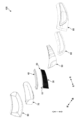
- the lens panel 50 has a concave lens portion (lens portion) 51, a convex lens portion (lens portion) 52, a vertical wall portion 53, and a light-transmitting pattern 55.
- the concave lens portion 51 has a shape that is concave toward the rear side.
- the concave lens portion 51 is formed into a plate shape using a material that can transmit light, and is curved from the top and bottom ends in the vertical direction to the center so that it is concave toward the rear side.
- the concave lens portion 51 has an incident surface 51a and an exit surface 51b.
- the incident surface 51a is located on the rear side, and light emitted from the inner lens 30 enters the incident surface 51a.
- the exit surface 51b is located on the front side, and emits light that enters from the incident surface 51a.
- the convex lens portion 52 has a shape that protrudes toward the front side.
- the convex lens portion 52 is formed into a plate shape using a material that can transmit light, and has a curved shape that protrudes toward the front side from the upper and lower ends in the vertical direction to the center.
- the convex lens portion 52 has an incident surface 52a and an exit surface 52b.
- the incident surface 52a is located on the rear side, and light emitted from the inner lens 30 enters the incident surface 52a.
- the exit surface 52b is located on the front side, and emits light that enters from the incident surface 52a.
- the vertical wall portion 53 is formed so as to connect the adjacent concave lens portion 51 and convex lens portion 52.
- the vertical wall portion 53 is formed so as to intersect in the left-right direction and extend along the front-rear direction. As shown in FIG. 7, the vertical wall portion 53 is formed so as to extend in the left-right direction from the concave lens portion 51 toward the convex lens portion 52.
- the vertical wall portion 53 has a light diffusing portion such as a grain formed on the surface 53a on the rear side.
- the light-transmitting pattern 55 is formed on the front surface of the lens panel 50.
- FIG. 8 also shows an enlarged cross-sectional view of the light-transmitting pattern 55.
- the light-transmitting pattern 55 has a light-reflecting layer 55a, a coating layer 55b, and openings 55c and 55d.
- the light reflecting layer 55a is formed over the entire front surface of the transparent member 50R (see FIG. 10) that constitutes the lens panel 50, i.e., the exit surface 51b of the concave lens portion 51, the exit surface 52b of the convex lens portion 52, the front surface 53b of the vertical wall portion 53, the front portion 61a and the lower surface 61b of the upper portion 61 of the inner panel 60, and the front portion 62a and the upper surface 62b of the lower portion 62.
- the light reflecting layer 55a is formed using a material capable of reflecting light, such as a metal material such as aluminum.
- the light reflecting layer 55a may also be formed using a resin material capable of reflecting light, such as a white resin.
- the coating layer 55b is formed over the entire surface of the light reflecting layer 55a.
- the coating layer 55b is formed using a material of a predetermined color, such as black resin.
- the coating layer 55b can be formed, for example, with a glossy surface.
- Opening 55c is formed in the light reflecting layer 55a and the paint layer 55b in the portion that is disposed on the exit surface 51b of the concave lens portion 51.
- Opening 55d is formed in the light reflecting layer 55a and the paint layer 55b in the portion that is disposed on the exit surface 52b of the convex lens portion 52.
- Openings 55c and 55d are formed penetrating the light reflecting layer 55a and the paint layer 55b.
- Openings 55c and 55d are portions that expose the exit surfaces 51b and 52b from the light reflecting layer 55a and the paint layer 55b.
- Openings 55c and 55d are portions through which light emitted from the exit surfaces 51b and 52b passes.
- the openings 55c, 55d are formed, for example, by applying a so-called laser etching process in which a laser beam is applied from the side of the coating layer 55b to the portion where the light reflecting layer 55a and the coating layer 55b are laminated.
- the exposed portions of the emission surfaces 51b, 52b exposed at the openings 55c, 55d may be formed as rough surfaces or recessed toward the back side with respect to other portions of the emission surfaces 51b, 52b, for example, during the process of performing the laser etching.
- the openings 55c are formed in a band shape extending in the left-right direction.
- the openings 55c are formed so that the vertical dimension (width) is constant in the left-right direction.
- a plurality of openings 55c are arranged in the up-down direction.
- the exit surface 51b of the concave lens portion 51 is formed so as to be recessed toward the rear side from the upper and lower ends in the up-down direction to the center.
- the openings 55c are formed so that the opening area per unit area is larger from the center in the up-down direction to both ends in the up-down direction.
- the openings 55c formed on the upper and lower sides in the up-down direction are formed so that the opening area is larger than that of the openings 55c formed in the center in the up-down direction.
- the light transmission pattern 55 is formed so that the both ends in the up-down direction located on the front side of the exit surface 51b of the concave lens portion 51 transmit more light per unit area than the central part in the up-down direction located on the back side. Therefore, when the light-emitting state is viewed from the front side, it appears three-dimensional from both ends in the up-down direction to the center, as if they are located from the front side to the back side.
- Opening 55d is formed to extend in the up-down direction. Multiple openings 55d are arranged in the left-right direction. In this way, the orientations of openings 55c and openings 55d are different between the light transmission pattern 55 arranged on the concave lens portion 51 and the light transmission pattern 55 arranged on the convex lens portion 52, that is, they are arranged with a 90° shift.
- the exit surface 52b of the convex lens portion 52 is formed so as to protrude from the top and bottom ends to the center in the vertical direction toward the front side.
- the opening 55d is formed so that the opening area per unit area becomes larger from the top and bottom ends to the center in the vertical direction.
- the dimension (width) in the left and right direction becomes smaller (thinner) from the center in the vertical direction to the top and bottom ends in the vertical direction. Therefore, the opening 55d is formed so that the opening area becomes larger from the top and bottom ends to the center in the vertical direction.
- the light transmission pattern 55 is formed so that the vertical center located on the front side of the exit surface 52b of the convex lens portion 52 transmits more light per unit area than the top and bottom ends located on the back side. Therefore, when the light-emitting state is viewed from the front side, it appears three-dimensional from the vertical center to both ends in the vertical direction, as if it is located from the front side to the back side.
- the shape shown in FIG. 9(A) is a shape in which each opening extends in one direction, and the width dimension increases from both ends in the longitudinal direction toward the center. In other words, the width dimension tapers from the center to both ends in the longitudinal direction. This shape is applied, for example, to opening 55d of light transmission pattern 55 described above.
- the shape shown in FIG. 9(B) is a shape in which each opening extends in one direction, and the widthwise dimension is uniform from both longitudinal ends to the center. This shape is applied to, for example, opening 55c of light-transmitting pattern 55 described above.
- the shape shown in FIG. 9(C) is a shape in which circular openings are arranged in a staggered pattern so that they are offset by a radius in the left-right direction.
- the shape of the opening shown in FIG. 9(C) may be applied to at least one of the openings 55c, 55d of the light transmission pattern 55 described above.
- the surface of the paint layer 55b becomes the surface 53c of the vertical wall portion 53.
- the surface 53c of the vertical wall portion 53 becomes a reflective surface 58 that reflects light emitted from the exit surface 51b of the concave lens portion 51 and passing through the opening 55c toward the front of the vehicle.
- the surface 53c (reflective surface 58) of the vertical wall portion 53 it is visually recognized as having an image of the opening 55c reflected on the surface 53c when viewed from the front side.
- an opening may be formed in the portion of the light transmission pattern 55 that is located in the vertical wall portion 53.
- the surface 53c of the vertical wall portion 53 is disposed at a position on the extension of the opening 55c.
- an image of the opening 55c is reflected on the surface 53c of the vertical wall portion 53, so that the image of the opening 55c can be visually perceived as if it is connected to the surface 53c.
- the surface 53c of the vertical wall portion 53 disposed on the inside of the vehicle can be formed to have a higher light reflectance than other portions. In this configuration, when viewed from outside the vehicle, the image of the opening 55c reflected on the surface 53c of the vertical wall portion 53 on the inside of the vehicle can be visually perceived more clearly.
- a light diffusion section 59 is formed on the entire rear surface of the transparent member 50R (see FIG. 11) constituting the lens panel 50.
- the light diffusion section 59 may be, for example, textured.
- a light diffusion member may be disposed as the light diffusion section 59.
- the light diffusion section 59 may be selectively formed on, for example, the entrance surface 51a of the concave lens section 51, the entrance surface 52a of the convex lens section 52, the surface 53a on the rear surface of the vertical wall section 53, etc.
- the inner panel 60 supports the lens panel 50.
- the inner panel 60 is formed integrally with the lens panel 50.
- the inner panel 60 has an upper portion 61 and a lower portion 62.
- the upper portion 61 supports the upper ends of the concave lens portion 51 and the convex lens portion 52.
- the upper portion 61 has a front portion 61a and a bottom portion 61b.
- the front portion 61a is disposed on the front side of the upper portion 61.
- the bottom portion 61b is disposed at the bottom end of the upper portion 61.
- the bottom portion 61b is disposed so as to protrude forward from the upper ends of the emission surfaces 51b, 52b.
- the bottom portion 61b is formed so as to slope upward from the upper ends of the emission surfaces 51b, 52b towards the front side.
- the lower portion 62 supports the lower ends of the concave lens portion 51 and the convex lens portion 52.
- the lower portion 62 has a front portion 62a and an upper portion 62b.
- the front portion 62a is disposed on the front side of the lower portion 62.
- the upper portion 62b is disposed at the upper end of the lower portion 62.
- the upper portion 62b is disposed so as to protrude forward from the lower ends of the emission surfaces 51b, 52b.
- the upper portion 62b is formed so as to slope downward from the lower ends of the emission surfaces 51b, 52b towards the front side.
- the lower surface portion 61b serves as a reflective surface 58 that reflects light emitted from the emission surfaces 51b, 52b and passing through the openings 55c, 55d, toward the front of the vehicle.
- the upper surface portion 62b serves as a reflective surface 58 that reflects light emitted from the emission surfaces 51b, 52b and passing through the openings 55c, 55d, toward the front of the vehicle.
- openings 55c, 55d When light passing through openings 55c, 55d is reflected by bottom surface 61b and top surface 62b, the images of openings 55c, 55d are visible on bottom surface 61b and top surface 62b when viewed from the front side.
- the convex side regions 61c, 62c of the lower surface portion 61b and the upper surface portion 62b, which are arranged at the upper and lower ends of the convex lens portion 52, are located in the direction in which the opening 55d of the light transmission pattern 55 formed in the convex lens portion 52 extends, i.e., on the extension of the opening 55d.
- the convex side regions 61c, 62c can be formed so as to have a higher light reflectance than other parts of the lower surface portion 61b and the upper surface portion 62b. With this configuration, the image of the opening 55d reflected in the convex side regions 61c, 62c can be more clearly visually recognized.
- the inner housing 70 supports the light source 10, light guide 20, inner lens 30, reflector 40, lens panel 50, and inner panel 60.
- the outer lens 80 is disposed on the front side, i.e., rear side, of the lens panel 50.
- the outer lens 80 directs the light emitted from the lens panel 50 to the outside of the vehicle lamp 100.
- the outer lens 80 is plate-shaped.
- the outer lens 80 has a shape that curves toward the rear side from the inside of the vehicle to the outside of the vehicle.
- the outer lens 80 is formed, for example, using a resin material that is transparent or has a color similar to the lighting color.
- the outer housing 90 forms a lamp chamber between itself and the outer lens 80.
- the lamp chamber accommodates or supports the light source 10, light guide 20, inner lens 30, reflector 40, lens panel 50, inner panel 60, and inner housing 70.
- the vehicle lamp 100 configured as described above is turned on.
- the vehicle lamp 100 acquires an operation signal from the operation device.
- a control circuit provided on the board or the like of the light source 10 controls the light emission of the light source 10 according to the acquired signal.
- light is emitted from the light emitting surface 11 of the light source 10.
- This light enters the light guide section 22 from the entrance surface 21 of the light guide 20.
- the light that enters the light guide section 22 is guided by the light guide section 22 and enters the exit section 23, where it is internally reflected by the prism section 23b and emitted downward from the side surface 23a.
- the light emitted downward from the side surface 23a of the emission portion 23 enters the inner lens 30 from the end faces 31a, 32a.
- the light that enters the inner lens 30 is internally reflected by the prism portions 31p, 32p, etc., and is emitted to the front side of the inner lens 30.
- the light that is emitted to the front side of the inner lens 30 reaches the lens panel 50 and enters through the entrance surface 51a of the concave lens portion 51 and the entrance surface 52a of the convex lens portion 52.
- a portion of the light incident on the incident surface 51a (hereinafter referred to as light L1) reaches the exit surface 51b and passes through the opening 55c to be emitted to the front side.
- the light L1 that passes through the opening 55c passes through the outer lens 80 to be emitted to the rear of the vehicle.
- a portion of the light incident on the entrance surface 52b (hereinafter referred to as light L2) reaches the exit surface 52b, passes through the opening 55d, and is emitted to the front side.
- the light L2 that passes through the opening 55d passes through the outer lens 80 and is emitted to the rear of the vehicle.
- a portion of the light incident on the entrance surface 51 or the entrance surface 52b (hereinafter referred to as light L3) reaches the exit surface 51b or the exit surface 52b and is reflected toward the rear side by the light reflecting layer 55a.
- the reflected light L3 is reflected at each portion and travels again toward the front side, where it is reused.
- a portion of the light incident on the incident surface 51a (hereinafter referred to as light L4) reaches the exit surface 51b and passes through the opening 55c to be emitted to the front side.
- the light L4 that passes through the opening 55c is reflected to the front side by the surface 53b of the vertical wall portion 53 and reaches the outer lens 80. This light L4 passes through the outer lens 80 to be emitted to the rear of the vehicle.
- a portion of the light incident on the entrance surface 52a (hereinafter referred to as light L5) reaches the exit surface 52b and passes through the opening 55d to be emitted to the front side.
- the light L5 that passes through the opening 55d is reflected to the front side by the lower surface portion 61b or the upper surface portion 62b of the inner panel 60 and reaches the outer lens 80. This light L5 passes through the outer lens 80 to be emitted to the rear of the vehicle.
- the vehicle lamp 100 includes a light source unit U having a light source 10 and emitting light from the light source 10 to the front side, a lens panel 50 arranged on the front side of the light source unit U and having a lens section with a concave lens section 51 recessed on the back side and a convex lens section 52 protruding to the front side, and emitting light from the light source unit U to the front side from the emission surfaces 51b, 52b of the lens section (51, 52), and an outer lens 80 arranged on the front side of the lens panel 50 and emitting light emitted from the lens panel 50 to the front side, and a light transmission pattern 55 having openings 55c, 55d shaped to correspond to the shapes of the lens sections (51, 52) is formed on the front side surface of the lens panel 50.
- the lens panel 50 has a concave lens portion 51 and a convex lens portion 52, and a light transmission pattern 55 is formed on the front surface with openings 55c, 55d shaped to correspond to the shapes of the lens portions (51, 52), so that when viewed from the front, it is possible to achieve a three-dimensional light emission state with a sense of depth.
- the light transmission pattern 55 is formed so that the portion of the lens portion (51, 52) located on the front side transmits more light per unit area than the portion located on the rear side.
- the light-transmitting pattern 55 has a laminated portion formed of a light-reflecting layer 55a disposed on the front surface of the lens portion (51, 52) and a paint layer 55b laminated on the light-reflecting layer 55a, and the openings 55c, 55d are formed penetrating the light-reflecting layer 55a and the paint layer 55b.
- a light reflecting layer 55a is formed on the front surface of the lens portion (51, 52), so that light that does not pass through the openings 55c, 55d can be returned to the rear side and reused.
- a paint layer 55b is laminated on top of the light reflecting layer 55a, so that the light reflecting layer 55a can be hidden when viewed from the front side.
- the lens panel 50 has a light diffusion section 59 on the incident surface of the lens section (51, 52).
- the light diffusion section 59 is provided on the entrance surface of the lens section of the lens panel 50, so that the light entering the lens panel 50 can be diffused and emitted from the exit surfaces 51b, 52b and the openings 55c, 55d. This allows homogeneous light to be emitted toward the outer lens 80.
- the lens panel 50 has a reflecting surface 58 around the lens portion (51, 52) that reflects the light emitted from the emission surfaces 51b, 52b toward the front of the vehicle.
- a reflective surface 58 is provided around the lens portion (51, 52), so that in the light-emitting state, the observer can see the light reflected by the reflective surface 58 when viewed from the front side.
- the lens panel 50 has concave lens portions 51 and convex lens portions 52 arranged alternately in at least one of the left-right direction and the up-down direction when mounted on the vehicle, has a vertical wall portion 53 connecting adjacent concave lens portions 51 and convex lens portions 52, and the reflective surface 58 is formed on the surface 53b of the vertical wall portion 53.
- the upright wall portion 53 which is located on the vehicle inside side of the concave lens portion 51, has a surface 53b formed so that it has a higher light reflectance than other portions.
- This configuration allows an observer looking from outside the vehicle to more clearly see the image of the opening 55c reflected on the surface 53c of the standing wall portion 53 in the light-emitting state.
- the vehicle lamp 100 further includes an inner panel 60 that is disposed on the front side of the lens portion (51, 52) and supports the lens panel 50, and the reflective surface 58 is formed on the surface (lower surface portion 61b, upper surface portion 62b) of the inner panel 60 facing the lens portion (51, 52).
- This configuration allows the observer to see the light reflected on the surfaces (lower surface 61b, upper surface 62b) of the inner panel 60 facing the lens portion (51, 52).
- the light-transmitting pattern 55 is formed so that the openings 55c and 55d that transmit light extend in one direction, and the reflective surface 58 is positioned on the extension of the openings 55c and 55d.
- the portion of the reflective surface 58 to which the openings 55c and 55d extend is formed to have a higher light reflectance than other portions.
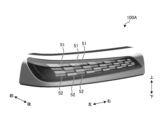
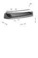
- FIGS. 12 to 16 are perspective views showing an example of the overall configuration of a vehicle lamp.
- FIGS. 12 to 16 show the vehicle lamp as viewed from the front side.
- the vehicle lamp 100 shown in FIG. 12 has the configuration described above. That is, the vehicle lamp 100 has a light transmission pattern 55 in which concave lens portions 51 and convex lens portions 52 are arranged alternately in the left-right direction, an opening 55c is provided on the exit surface 51b of the concave lens portion 51, and an opening 55d is provided on the exit surface 52b of the convex lens portion 52.
- the vehicle lamp 100A shown in FIG. 13 has concave lens portions 51 and convex lens portions 52 arranged alternately in the left-right direction as well as the up-down direction. In this way, the arrangement of the concave lens portions 51 and convex lens portions 52 is not limited to the configuration described above.
- the vehicle lamp 100B shown in FIG. 14 is configured such that a combination of triangular exit surfaces 54B in the lens panel 50B forms a portion that protrudes toward the front side of the lens panel 50B (convex lens portion) and a portion that is recessed toward the back side (concave lens portion).
- a configuration in which one concave lens portion and one convex lens portion are formed by multiple exit surfaces may be used.
- the shape of the exit surface is not limited to a triangular shape, and may be another type of polygon, such as a rectangle.
- Vehicle lamp 100C shown in FIG. 15 has a configuration in which concave lens portion 51C is formed in a groove shape relative to convex lens portion 52C. Vehicle lamp 100C is configured so that light is emitted from the entire exit surface of convex lens portion 52C, and the entire exit surface of concave lens portion 51C is light-shielded. In addition, convex lens portion 52C, which is located on the lower side in the vertical direction, also emits light from its lower surface, which is located below the exit surface.
- the vehicle lamp 100D shown in FIG. 16 is configured in the same way as the vehicle lamp 100C shown in FIG. 15, with the concave lens portion 51D formed in a groove shape relative to the convex lens portion 52D.
- the area of the emission surface per one convex lens portion 52D is smaller than in the vehicle lamp 100C. In this configuration, light is emitted from the entire convex lens portion 52D, and the entire emission surface of the concave lens portion 51C is shielded from light.
- vehicle lamps 100, 100A, 100B, 100C, and 100D by combining concave lens parts and convex lens parts and providing a light-transmitting pattern with openings shaped to correspond to the shapes of the lens parts, it is possible to realize a three-dimensional light-emitting state with a sense of depth.
- the light source unit U is described as having a configuration including a light source 10, a light guide 20, and an inner lens 30, but is not limited to this configuration.
- the configuration may be such that at least one of the light guide 20 and the inner lens 30 is not provided.
Landscapes
- Engineering & Computer Science (AREA)
- General Engineering & Computer Science (AREA)
- Non-Portable Lighting Devices Or Systems Thereof (AREA)
Abstract
Description
Claims (10)
- 光源を有し、前記光源からの光を正面側に出射する光源ユニットと、
前記光源ユニットの正面側に配置され、背面側に凹んだ凹状レンズ部及び正面側に突出した凸状レンズ部のレンズ部を有し、前記光源ユニットからの光を前記レンズ部の出射面から正面側に出射するレンズパネルと、
前記レンズパネルの正面側に配置され、前記レンズパネルから出射される光を正面側に出射するアウターレンズと
を備え、
前記レンズパネルの正面側の表面には、前記レンズ部の形状に対応した形状の開口部を有する光透過パターンが形成される
車両用灯具。 - 前記光透過パターンは、前記レンズ部において正面側に位置する部分の方が背面側に位置する部分よりも単位面積当たりの光の透過量が多くなるように形成される
請求項1に記載の車両用灯具。 - 前記光透過パターンは、前記レンズ部の正面側の表面上に配置される光反射層と、前記光反射層に積層される塗装層とで形成される積層部を有し、
前記開口部は、前記光反射層及び前記塗装層を貫通して形成される
請求項1に記載の車両用灯具。 - 前記レンズパネルは、前記レンズ部の入射面に光拡散部を有する
請求項3に記載の車両用灯具。 - 前記レンズパネルは、前記出射面から出射された光を車両前方に向けて反射する反射面を前記レンズ部の周囲に有する
請求項1に記載の車両用灯具。 - 前記レンズパネルは、前記凹状レンズ部及び前記凸状レンズ部が車両搭載状態における左右方向及び上下方向の少なくとも一方に交互に配置され、隣り合う前記凹状レンズ部と前記凸状レンズ部とを接続する立壁部を有し、
前記反射面は、前記立壁部の表面に形成される
請求項5に記載の車両用灯具。 - 前記凹状レンズ部の車両内側に配置される前記立壁部は、他の部分に比べて光反射率が高くなるように表面が形成される
請求項6に記載の車両用灯具。 - 前記レンズ部の正面側に配置され前記レンズパネルを支持するインナーパネルを更に備え、
前記反射面は、前記インナーパネルの前記レンズ部側の面に形成される
請求項5に記載の車両用灯具。 - 前記光透過パターンは、光を透過させる開口部が一方向に延びるように形成され、
前記反射面は、前記開口部の延長上の位置に配置される
請求項5に記載の車両用灯具。 - 前記反射面のうち前記開口部が延びる先に位置する部分は、他の部分に比べて光反射率が高くなるように形成される
請求項8に記載の車両用灯具。
Priority Applications (2)
| Application Number | Priority Date | Filing Date | Title |
|---|---|---|---|
| EP24832110.1A EP4737797A1 (en) | 2023-06-30 | 2024-06-28 | Vehicle lamp |
| CN202480042425.0A CN121368697A (zh) | 2023-06-30 | 2024-06-28 | 车辆用灯具 |
Applications Claiming Priority (2)
| Application Number | Priority Date | Filing Date | Title |
|---|---|---|---|
| JP2023-108909 | 2023-06-30 | ||
| JP2023108909A JP2025007480A (ja) | 2023-06-30 | 2023-06-30 | 車両用灯具 |
Publications (1)
| Publication Number | Publication Date |
|---|---|
| WO2025005252A1 true WO2025005252A1 (ja) | 2025-01-02 |
Family
ID=93939134
Family Applications (1)
| Application Number | Title | Priority Date | Filing Date |
|---|---|---|---|
| PCT/JP2024/023522 Ceased WO2025005252A1 (ja) | 2023-06-30 | 2024-06-28 | 車両用灯具 |
Country Status (4)
| Country | Link |
|---|---|
| EP (1) | EP4737797A1 (ja) |
| JP (1) | JP2025007480A (ja) |
| CN (1) | CN121368697A (ja) |
| WO (1) | WO2025005252A1 (ja) |
Citations (6)
| Publication number | Priority date | Publication date | Assignee | Title |
|---|---|---|---|---|
| WO2013132764A1 (ja) * | 2012-03-08 | 2013-09-12 | 株式会社小糸製作所 | 車両用灯具 |
| JP2017107652A (ja) * | 2015-12-07 | 2017-06-15 | 株式会社小糸製作所 | 車両用灯具 |
| JP2018120037A (ja) | 2017-01-24 | 2018-08-02 | スタンレー電気株式会社 | 意匠レンズ及びその製造方法、並びに車両用灯具 |
| JP2020038800A (ja) * | 2018-09-05 | 2020-03-12 | スタンレー電気株式会社 | 車両用灯具 |
| JP2021097016A (ja) * | 2019-12-19 | 2021-06-24 | スタンレー電気株式会社 | 車両用灯具 |
| JP2023079918A (ja) * | 2021-11-29 | 2023-06-08 | 市光工業株式会社 | 車両用灯具 |
-
2023
- 2023-06-30 JP JP2023108909A patent/JP2025007480A/ja active Pending
-
2024
- 2024-06-28 WO PCT/JP2024/023522 patent/WO2025005252A1/ja not_active Ceased
- 2024-06-28 EP EP24832110.1A patent/EP4737797A1/en active Pending
- 2024-06-28 CN CN202480042425.0A patent/CN121368697A/zh active Pending
Patent Citations (6)
| Publication number | Priority date | Publication date | Assignee | Title |
|---|---|---|---|---|
| WO2013132764A1 (ja) * | 2012-03-08 | 2013-09-12 | 株式会社小糸製作所 | 車両用灯具 |
| JP2017107652A (ja) * | 2015-12-07 | 2017-06-15 | 株式会社小糸製作所 | 車両用灯具 |
| JP2018120037A (ja) | 2017-01-24 | 2018-08-02 | スタンレー電気株式会社 | 意匠レンズ及びその製造方法、並びに車両用灯具 |
| JP2020038800A (ja) * | 2018-09-05 | 2020-03-12 | スタンレー電気株式会社 | 車両用灯具 |
| JP2021097016A (ja) * | 2019-12-19 | 2021-06-24 | スタンレー電気株式会社 | 車両用灯具 |
| JP2023079918A (ja) * | 2021-11-29 | 2023-06-08 | 市光工業株式会社 | 車両用灯具 |
Also Published As
| Publication number | Publication date |
|---|---|
| EP4737797A1 (en) | 2026-05-06 |
| JP2025007480A (ja) | 2025-01-17 |
| CN121368697A (zh) | 2026-01-20 |
Similar Documents
| Publication | Publication Date | Title |
|---|---|---|
| JP5911397B2 (ja) | 車両用前照灯 | |
| JP2012028155A (ja) | 車両用灯具ユニット | |
| JP2021180075A (ja) | 車両用灯具 | |
| JP7482687B2 (ja) | 車両用灯具 | |
| JP7062883B2 (ja) | 車両用灯具 | |
| JP2013191403A (ja) | ドアミラー用サイドターンランプ | |
| JP2025161980A (ja) | 車両用灯具 | |
| WO2025005252A1 (ja) | 車両用灯具 | |
| JP7775795B2 (ja) | 車両用灯具 | |
| JP7139200B2 (ja) | 車両用灯具 | |
| JP7483586B2 (ja) | 車両用灯具 | |
| JP5808995B2 (ja) | 車両用灯具 | |
| JP7587453B2 (ja) | 車両用導光体及び車両用灯具 | |
| JP7707881B2 (ja) | 車両用灯具 | |
| KR102691868B1 (ko) | 차량용 램프의 아우터렌즈 및 이를 구비한 차량용 램프 | |
| JP7694236B2 (ja) | 車両用灯具 | |
| WO2025005251A1 (ja) | 車両用灯具 | |
| JP7772664B2 (ja) | 車両用灯具 | |
| US12392465B2 (en) | Vehicle lamp | |
| JP2024092784A (ja) | 車両用灯具 | |
| WO2025005190A1 (ja) | 車両用灯具 | |
| JP7675573B2 (ja) | 車両用信号灯具、及びレンズ体 | |
| JP2024136165A (ja) | 車両用灯具 | |
| JP2026023076A (ja) | 車両用灯具 | |
| JP6215415B2 (ja) | 車両用灯具 |
Legal Events
| Date | Code | Title | Description |
|---|---|---|---|
| 121 | Ep: the epo has been informed by wipo that ep was designated in this application |
Ref document number: 24832110 Country of ref document: EP Kind code of ref document: A1 |
|
| WWE | Wipo information: entry into national phase |
Ref document number: 2024832110 Country of ref document: EP |
|
| NENP | Non-entry into the national phase |
Ref country code: DE |
|
| ENP | Entry into the national phase |
Ref document number: 2024832110 Country of ref document: EP Effective date: 20260130 |
|
| ENP | Entry into the national phase |
Ref document number: 2024832110 Country of ref document: EP Effective date: 20260130 |