WO2025005234A1 - 回転繰出容器 - Google Patents
回転繰出容器 Download PDFInfo
- Publication number
- WO2025005234A1 WO2025005234A1 PCT/JP2024/023484 JP2024023484W WO2025005234A1 WO 2025005234 A1 WO2025005234 A1 WO 2025005234A1 JP 2024023484 W JP2024023484 W JP 2024023484W WO 2025005234 A1 WO2025005234 A1 WO 2025005234A1
- Authority
- WO
- WIPO (PCT)
- Prior art keywords
- holder
- barrel
- threaded rod
- shaft
- rod
- Prior art date
- Legal status (The legal status is an assumption and is not a legal conclusion. Google has not performed a legal analysis and makes no representation as to the accuracy of the status listed.)
- Ceased
Links
Images







Classifications
-
- A—HUMAN NECESSITIES
- A45—HAND OR TRAVELLING ARTICLES
- A45D—HAIRDRESSING OR SHAVING EQUIPMENT; EQUIPMENT FOR COSMETICS OR COSMETIC TREATMENTS, e.g. FOR MANICURING OR PEDICURING
- A45D40/00—Casings or accessories specially adapted for storing or handling solid or pasty toiletry or cosmetic substances, e.g. shaving soaps or lipsticks
- A45D40/02—Casings wherein movement of the lipstick or like solid is a sliding movement
- A45D40/04—Casings wherein movement of the lipstick or like solid is a sliding movement effected by a screw
-
- B—PERFORMING OPERATIONS; TRANSPORTING
- B65—CONVEYING; PACKING; STORING; HANDLING THIN OR FILAMENTARY MATERIAL
- B65D—CONTAINERS FOR STORAGE OR TRANSPORT OF ARTICLES OR MATERIALS, e.g. BAGS, BARRELS, BOTTLES, BOXES, CANS, CARTONS, CRATES, DRUMS, JARS, TANKS, HOPPERS, FORWARDING CONTAINERS; ACCESSORIES, CLOSURES, OR FITTINGS THEREFOR; PACKAGING ELEMENTS; PACKAGES
- B65D83/00—Containers or packages with special means for dispensing contents
Definitions
- This invention relates to a rotary dispenser container for use as a stick-shaped cosmetic container, writing implement, applicator, etc., which dispenses stick-shaped members such as stick-shaped cosmetics, stick-shaped writing implements, and stick-shaped applicators from the container.
- Rotary dispensing containers accommodating solid-core eyeliners having an elliptical or oval cross-sectional shape are disclosed in Patent Documents 1 and 2.
- the solid lead is configured to be dispensed in one direction, and therefore it is impossible to return the solid lead dispensed from the front end of the barrel by the dispensing operation back into the barrel.
- Patent Document 3 a rotary dispenser capable of returning the dispensed solid lead into the barrel, which is disclosed in Patent Document 3.
- the rotary dispenser container disclosed in Patent Document 3 is provided with a threaded rod that moves forward or backward by rotating the rear barrel relative to the front barrel, and as the threaded rod moves forward, the solid lead is pushed by the threaded rod and dispensed from the front barrel. Furthermore, as the threaded rod retracts, the front end of the threaded rod pulls the holder which covers the outside of the solid lead, and the solid lead is returned together with the holder into the front barrel.
- the solid lead To return the drawn-out solid lead back into the front barrel, the solid lead must be returned together with the holder into the front barrel with a specified length of solid lead drawn out from the front end of the cylindrical holder. As a result, the tip of the solid lead protruding from the holder is left floating without being supported within the front barrel, and if the barrel is subjected to an impact in this state, such as being dropped, the tip of the solid lead protruding from the holder will be broken by the impact, causing a problem.
- This invention was made in consideration of the above-mentioned circumstances, and its main objective is to provide a rotary dispenser that can effectively prevent the breakage of the solid core contained within the barrel due to impacts applied to the barrel.
- the rotary dispensing container of the present invention which has been made to solve the above-mentioned problems, is a rotary dispensing container comprising a barrel in which a front barrel and a rear barrel are configured to be rotatable relative to one another, a threaded rod disposed at the rear of the barrel and adapted to move forward or backward within the barrel in response to the relative rotation of the front barrel and the rear barrel, and a rod-shaped member (solid core) disposed at the front of the barrel and adapted to move axially within the front barrel depending on the forward or backward movement of the threaded rod, the rod-shaped member being housed within a holder which covers the outer periphery of the rod-shaped member, the tip of the holder having a number of protrusions which extend axially forward, and A holder guide is provided with protrusions arranged in the circumferential direction, and multiple guide grooves are formed along the inner circumferential surface of the tip barrel, extending in the axial direction and into which the protru
- the tip of the rod-shaped member protruding from the holder is supported by the multiple protrusions provided on the holder guide.
- the rear axle is rotatably attached to the center axle attached to the front axle, so that the front and rear axles are configured to be rotatable relative to one another, and a male thread formed on the threaded rod is screwed into a female thread formed on the center axle, and the threaded rod is formed with a flange portion that is axially movable within the rear axle and rotates the threaded rod in the same direction as the rear axle rotates.
- a rib protruding in the axial direction is formed within the rear axle along the axial direction, a flange formed on the threaded rod is movable in the axial direction along the rib, and a portion of the flange abuts against the rib when the rear axle rotates, so that the threaded rod rotates in the same direction as the rear axle rotates.
- a large diameter section with an axial hole is formed at the front end of the threaded rod via a straight-shaped shaft body, and the large diameter section is configured so that as the threaded rod advances, it causes the rod-shaped member to protrude from the front shaft, and as the threaded rod retreats, it comes into contact with the inside of the holder, performing a pulling action that causes the holder to retreat together with the rod-shaped member.
- the solid lead as a rod-shaped member is housed within the holder and is arranged so as to be able to protrude and retract from the front barrel as the threaded rod moves forward and backward.
- the tip of the holder is provided with a holder guide having multiple protrusions extending axially forward and arranged along the circumferential direction, so that when the rod-shaped member retracts together with the holder and is housed in the front barrel, the tip of the rod-shaped member protruding from the holder is supported by the multiple protrusions provided on the holder guide.
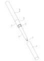
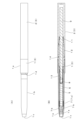
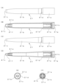
- FIG. 1 is a perspective view of a rotary dispensing container according to a first embodiment of the present invention with the cap removed; 1A and 1B show a rotary dispensing container according to a first embodiment without the cap, in which (A) is an external view and (B) is a cross-sectional view taken along the axial direction. 2B is a cross-sectional view taken along the axial direction of the rotary dispensing container, the cross-section being shown in FIG. 2A rotated by 90 degrees relative to FIG. 2A.
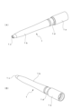
- FIG. FIG. 2 is an enlarged perspective view of the vicinity of the tip of the rotary dispensing container in the first embodiment, with a portion of the front barrel broken away.
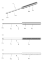
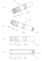
- FIG. 1A and 1B show a single-item configuration of a front barrel according to a first embodiment, in which FIG. 1A is a perspective view with the tip end side facing forward, and FIG. 1 shows the individual configuration of the front barrel in the first embodiment, with (A) being a top view, (B) being a longitudinal cross-sectional view along the axial direction in (A), (C) being a front view, (D) being a longitudinal cross-sectional view along the axial direction in (C), (E) being a left side view, and (F) being a right side view.
- FIG. 1 shows the individual configuration of the holder in the first embodiment, where (A) is a top view, (B) is a longitudinal cross-sectional view along the axial direction in (A), (C) is a front view, and (D) is a longitudinal cross-sectional view along the axial direction in (C).
- This shows the state in which a holder guide is attached to the front end of the holder in the first embodiment, where (A) is a top view, (B) is a longitudinal cross-sectional view along the axial direction of (A), (C) is a front view, and (D) is a longitudinal cross-sectional view along the axial direction of (C).
- FIG. 1A and 1B show a state before the holder guide is attached to the holder according to the first embodiment, in which FIG. 1A is a perspective view with the holder guide side facing forward, and FIG. 1A and 1B show a state in which a holder guide is attached to a holder according to a first embodiment, in which FIG. 1A is a perspective view with the holder guide side facing forward, and FIG.
- FIG. 1 shows the individual configuration of the holder guide of the first embodiment, with (A) being an oblique view with the tip end side facing forward, (B) being an oblique view with the rear end side facing forward, (C) being a top view, (D) being a longitudinal cross-sectional view along the axial direction of (C), (E) being a front view, (F) being a longitudinal cross-sectional view along the axial direction of (E), (G) being a left side view, and (H) being a right side view.
- 1A shows a single-item configuration of a center shaft according to a first embodiment, in which (A) is an oblique view with the tip end side facing forward, (B) is an oblique view with the rear end side facing forward, (C) is a top view, and (D) is a cross-sectional view along the axial direction.
- 1A shows a single component configuration of a threaded rod according to a first embodiment, in which (A) is an oblique view with the tip side facing forward, (B) is a front view, (C) is a top view, and (D) is a cross-sectional view along the axial direction.
- 1A shows a single component configuration of a screw body according to a first embodiment, in which (A) is an oblique view with the tip end side facing forward, (B) is an oblique view with the rear end side facing forward, (C) is a front view, and (D) is a cross-sectional view along the axial direction.
- 1 shows the single-item configuration of a rear body according to a first embodiment, in which (A) is a cross-sectional view taken along the axial direction, and (B) is a cross-sectional view taken along line J-J in (A) as viewed in the direction of the arrows.
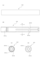
- 10A and 10B show a rotary dispensing container according to a second embodiment without the cap, in which (A) is an external view and (B) is a cross-sectional view taken along the axial direction. 12B is a cross-sectional view taken along the axial direction of the rotary dispensing container, the cross-section being shown in FIG. 12A rotated by 90 degrees relative to FIG. 12A.
- FIG. 11 shows the individual configuration of the front barrel in the second embodiment, with (A) being a top view, (B) being a longitudinal cross-sectional view along the axial direction in (A), (C) being a front view, (D) being a longitudinal cross-sectional view along the axial direction in (C), (E) being a left side view, and (F) being a right side view.
- 10A shows a single-item configuration of a center shaft according to a second embodiment, in which (A) is an oblique view with the tip end side facing forward, (B) is an oblique view with the rear end side facing forward, (C) is a top view, and (D) is a cross-sectional view along the axial direction.
- 10A shows a single component configuration of a threaded rod according to a second embodiment, in which (A) is an oblique view with the tip side facing forward, (B) is a front view, (C) is a top view, (D) is a cross-sectional view along the axial direction, and (E) is a right side view.
- 10 shows the single-item configuration of a rear axle according to a second embodiment, in which (A) is a front view, (B) is a cross-sectional view along the axial direction, (C) is a left side view, and (D) is a cross-sectional view taken along the K-K line shown in (B) as viewed in the direction of the arrow.
- a rotary dispensing container according to the present invention will be described based on an embodiment of a cosmetic tool that uses a solid-core eyeliner as the rod-shaped member contained within the container.
- the same parts are indicated by the same symbols, but in some drawings, due to space limitations, symbols are assigned to representative parts, and details are explained by quoting the symbols assigned to each drawing showing the individual component configuration.
- the rotary dispensing container of the first embodiment according to the present invention comprises a barrel tube 3 in which a rear barrel 2 formed in a cylindrical shape with a bottom is attached to a front barrel 1 so as to be rotatable relative to the front barrel 1.
- a small diameter portion 1b is formed whose diameter decreases toward the front, and an opening 1c is provided at the tip of small diameter portion 1b, through which a solid core 5 as a rod-shaped member described later appears and disappears.
- Cap 4 which is formed in a bottomed cylindrical shape so as to cover small diameter portion 1b of front barrel 1, is attached in the axial direction by abutting its open end against cap attachment step 1d provided on front barrel 1.
- the appearance of the rotary dispensing container with cap 4 attached is configured to form an elongated cylindrical body with a roughly uniform diameter in the longitudinal direction.
- FIGS. 2A and 2B show an external view and a cross-sectional view of the rotary dispensing container with cap 4 removed, with solid core eyeliner 5 (hereinafter sometimes simply referred to as solid core 5) as a rod-shaped member contained within front barrel 1.
- solid core 5 is contained within holder 6 which covers its outer periphery, and holder 6 is disposed with cylindrical base end 7a of holder guide 7 attached to the front end thereof in contact with the inside of front barrel 1.
- a piston 8 is housed in the rear end of the holder 6, which is in contact with the inner surface of the holder 6 and can slide in the axial direction of the holder 6.
- This piston 8 is pushed by a threaded rod 9, and acts to advance the solid core 5 in the holder 6 from the front end opening 1c of the front barrel 1.
- the piston 8 also functions as a sealing member to prevent the rear side of the solid core 5 from coming into contact with the air and volatilizing the solvent. This prevents the last remaining part of the solid core 5 from hardening, which can lead to a decrease in functionality.
- the threaded rod 9 is disposed to the rear of the solid lead 5 and piston 8, and this threaded rod 9 moves forward or backward within the barrel tube 3 due to the relative rotation of the rear barrel 2 with respect to the front barrel 1.
- the forward or backward movement of this threaded rod 9 is effected by a threaded body 11 disposed within the rear barrel 2 and a center shaft 12 that is press-fitted into the rear end of the front barrel 1.
- the forward or backward action of the threaded rod 9 will be described in more detail in the explanation of the individual components of the threaded body 11 and center shaft 12 described below.
- the small diameter portion 1b, opening 1c, solid lead 5, holder 6, holder guide 7, piston 8 and the front half of threaded rod 9 in the front barrel 1 each have an elliptical cross section perpendicular to the axial direction.
- An annular elastic member (O-ring) 13 is attached along the outer periphery of the front end of the threaded rod 9, and when the threaded rod 9 moves forward, this O-ring 13 slides against the inner surface of the holder 6 and moves forward within the holder 6, and also acts to push the solid core 5 forward from the holder 6 via the piston 8 at the tip of the threaded rod 9. Furthermore, when the threaded rod 9 moves backward, the O-ring 13 is in pressure contact with the inner surface of the holder 6 and operates to move the solid lead 5 backward together with the holder 6 within the front barrel 1 .
- FIG. 3 shows a partially cutaway view of small diameter portion 1b of front barrel 1 of the rotary dispensing container.
- the holder guide 7 is attached to the tip of the holder 6 which covers the outer circumference of the solid core 5, and this holder guide 7 has multiple (four in this example) protrusions 7b extending axially forward from a cylindrical base end 7a, each of which is arranged along the circumferential direction of the base end 7a.
- a plurality of guide grooves 1e are intermittently formed along the inner circumferential surface on the tip side of front barrel 1, extending in the axial direction and allowing each of the protrusions 7b of holder guide 7 to enter and slide each of the protrusions 7b in the axial direction.
- FIGS. 4A to 11 show the respective parts used in the rotary dispensing container shown in FIGS. 1 to 3, either individually or in pairs of two parts. The configuration of each of the parts will be described below with reference to FIGS. 4A to 11.
- 4A and 4B show the individual configuration of the front barrel 1, which, as explained above, has a cylindrical section 1a at the rear end, and a small diameter section 1b with an elliptical cross section perpendicular to the axis formed in front of the cylindrical section 1a.
- An opening 1c is formed at the tip of the small diameter section 1b to support the solid core 5 so that it can be retracted, and a cap mounting step 1d is formed between the cylindrical section 1a and the small diameter section 1b.
- a step 1f is formed so that the inner diameter of the small diameter portion 1b decreases from the inner surface toward the opening 1c.
- the base end 7a of the holder guide 7 attached to the front end of the holder 6 is engaged with this step 1f, and the step 1f functions as a stopper that prevents the holder 6 from moving forward. Therefore, hereinafter, the step 1f will be referred to as a stopper.
- a plurality of guide grooves 1e are provided from the stopper 1f toward the tip opening 1c, which receive the respective projections 7b of the holder guide 7 and support the holder 6 together therewith so as to be movable in the axial direction.
- An annular projection 1g is formed on the inner surface of the rear end opening of the cylindrical portion 1a, and this projection 1g is used as a fitting portion when a center shaft 12, which will be described later, is attached by press fitting.
- four long and short ribs 1h are formed at equal intervals along the axial direction on the inner peripheral surface of the cylindrical portion 1a adjacent to the annular protrusion 1g. These long and short ribs 1h are used for axial alignment when the center shaft 12 is press-fitted into the cylindrical portion 1a.
- Fig. 5A shows the individual configuration of holder 6 housed in front barrel 1
- Fig. 5B shows the state in which holder guide 7 is attached to the tip of holder 6.
- Fig. 6A and Fig. 6B are perspective views showing the state before and after holder guide 7 is attached to the tip of holder 6, respectively.
- this holder 6 has an elliptical cross-sectional shape in a direction perpendicular to the axis, and a solid core storage section 6a capable of storing a rod-shaped solid core 5 is formed along the axial direction inside.
- An annular rib 6b is integrally formed with the holder 6 in a protruding state on the outer periphery of the front end of the holder 6.
- This annular rib 6b is formed in order to obtain a certain degree of fitting strength when a holder guide 7, which will be described later, is attached to the front end of the holder 6.
- the holder 6 has a short cylindrical portion 6c at its rear end, the short cylindrical portion 6c being provided with a groove 6d along its periphery.
- the holder guide 7 shows the individual configuration of the holder guide 7 attached to the front end of the holder 6.
- the holder guide 7 has four protrusions 7b extending axially forward from a cylindrical base end 7a, each of which is arranged along the circumferential direction of the base end 7a.
- the elliptical base end 7a has flat surfaces 7a1 formed parallel to the top and bottom along the long axis of the ellipse.
- the front end of the holder 6 is inserted into an axial hole 7c formed in the base end 7a.
- the holder guide 7 is fitted and attached to the front end of the holder 6 with the front end of the holder 6 abutting against an annular step 7d (see Figures 7D and 7F) formed in the axial hole 7c.
- annular surface 7a2 In front of the base end 7a, i.e., at the base of the protrusion 7b, an annular surface 7a2 perpendicular to the axis is formed.
- this annular surface 7a2 is pushed by the threaded rod 9 and moves forward together with the holder 6 while housed within the tip barrel 1, it comes into contact with a stopper 1f [see Figure 4B] formed within the tip barrel 1, and acts to prevent the holder 6 from moving forward.
- the solid lead 5 housed within the holder 6 is pushed by the threaded rod 9 and piston 8 to move within the holder 6 and is forced out from the opening 1c of the tip barrel 1.
- each protrusion 7b formed on the base end 7a are arranged along the elliptical shape of the base end 7a, and the outer surface on the tip side of each protrusion 7b forms a tapered surface 7b1 that is inclined toward the axial direction.
- the inner surface of each protrusion 7b is formed along the elliptical peripheral surface of the solid lead 5 delivered from the holder 6, forming a holding surface 7b2 for the solid lead 5. Therefore, the solid lead 5 protruding from the holder 6 is supported by the inner holding surface 7b2 of each protrusion 7b.
- the solid core 5 loaded into the holder 6 contains a volatile component as an eyeliner, and examples of such components include volatile silicones (cyclopentasiloxane, methyltrimethicone, dimethicone, etc.), volatile hydrocarbons (isododecane, light isoparaffin, etc.), and film-forming resins that dissolve in these solvents.
- volatile silicones cyclopentasiloxane, methyltrimethicone, dimethicone, etc.
- volatile hydrocarbons isododecane, light isoparaffin, etc.
- film-forming resins that dissolve in these solvents.
- FIG. 8 shows the structure of center barrel 12, which is attached to the rear end of front barrel 1 by press fitting.
- This center shaft 12 has a threaded rod insertion hole 12a formed at its front end, and this threaded rod insertion hole 12a is formed in a similar elliptical or rectangular shape so that an elliptical shaft body 9a formed in the front half of the threaded rod 9 described later can be inserted therethrough.
- the center shaft 12 is formed with, in order, a pair of circular protrusions 12b formed toward both outer sides of the shaft, a first annular rib 12c protruding in the circumferential direction, an O-ring mounting groove 12d, and a second annular rib 12e protruding in the circumferential direction.
- the pair of circular protrusions 12b are selectively inserted between four long and short ribs 1h formed within the cylindrical portion 1a of the front barrel 1, and are used to align the front barrel 1 and center barrel 12 in the axial direction.
- first annular rib 12c engages with annular protrusion 1g formed within cylindrical portion 1a of front barrel 1, and acts so that center barrel 12 is attached and fitted into the rear end portion of front barrel 1 by press fitting.
- an O-ring 14 shown in FIGS. 2A and 2B is mounted in the O-ring mounting groove 12d, and is configured so that the O-ring 14 comes into sliding contact with the inner circumferential surface of the rear axle 2 in the axial rotation direction.
- an annular rib 12e that protrudes in the circumferential direction near the rear end of the center shaft 12 acts as a retainer for the rear axle 2 that is attached to the rear end of the center shaft 12 to prevent it from slipping out.
- Fig. 9 shows the single component structure of the threaded rod 9.
- the threaded rod 9 has an elliptical shaft body 9a whose front half has an elliptical cross section perpendicular to the axis, and an O-ring mounting groove 9b is formed at its tip.
- an annular elastic member (O-ring) 13 is mounted in this mounting groove 9b.
- the rear half of the threaded rod 9 has a substantially circular cross section with male threads 9c formed along both the upper and lower surfaces, and flat portions 9d formed in the longitudinal direction along both side surfaces.
- the threaded body 11 shows the structure of the threaded body 11.
- the threaded body 11 is formed in a cylindrical shape and has a female thread 11a formed on the inner peripheral surface of the rear end portion.
- the female thread 11a is to be screwed into the male thread 9c of the threaded rod 9 shown in FIG.
- a plurality of anti-rotation ribs 11b are formed along the axial direction on the outer periphery of the front end of the threaded body 11, and these ribs 11b are formed at approximately equal intervals in the circumferential direction.
- the threaded body 11 shows the single-piece structure of the rear axle 2, which is formed into a cylindrical shape with a closed rear end.
- a plurality of vertical ribs 2a are formed on the inner peripheral surface near the opening of the front end at approximately equal intervals along the inner peripheral surface.
- An annular rib 2b is formed so as to protrude from the inner circumferential surface at a position closer to the front end opening than the positions at which the plurality of vertical ribs 2a are formed.
- the annular rib 2b protruding from this inner peripheral surface overcomes the annular rib 12e formed on the rear end of the center axle 12 in the axial direction, thereby preventing the center axle 12 and the rear axle 2 from coming loose and connecting them so as to allow relative rotation.
- the front end of center shaft 12 is press-fitted into front shaft 1 , so that front shaft 1 and rear shaft 2 are configured to be able to rotate relative to each other via center shaft 12 .
- FIG. 3 shows a state in which the tip of solid lead 5, which has been unwound from front barrel 1, has been returned into front barrel 1 by the above-mentioned operation.
- the solid lead 5 protruding from the front end of the holder 6 that has been returned into the front barrel 1 is supported and held by multiple (four) protrusions 7b provided on the holder guide 7.
- the inner surface of each protrusion 7b that supports the solid lead 5 constitutes a holding surface 7b2 for the solid lead 5 that follows the elliptical circumferential surface of the solid lead 5 that is fed out of the holder 6 [see Figure 7].
- the solid lead 5 protruding from the holder 6 can be supported without any gaps by the inner holding surfaces 7b2 of each protrusion 7b. Therefore, it is possible to provide a rotary dispenser container that can effectively prevent problems such as cracking or breaking the solid core 5 protruding from the holder 6, even if the container (cylinder 3) is subjected to impact, for example, by accidentally dropping the cosmetic tool.
- FIG. 12A to 16 a second embodiment of a rotary dispensing container according to the present invention will be described with reference to FIGS. 12A to 16.
- the components used in the rotary dispensing container of the first embodiment other than the front barrel 1, rear barrel 2, threaded rod 9, threaded body 11, and center barrel 12, are the same components that are also used in the second embodiment. Therefore, in the following, the components that are common to the first embodiment will be denoted by the same reference numerals, and their explanation will be omitted as appropriate, and the configuration of the new components used in the second embodiment will be mainly explained.
- front shaft 21, rear shaft 22, threaded rod 23, and center shaft 24 equipped with a threaded body are used as equivalents to the front shaft 1, rear shaft 2, threaded rod 9, threaded body 11, and center shaft 12 used in the first embodiment.
- FIGS. 12A and 12B show the exterior configuration and an axial cross-sectional view of a rotary dispensing container according to the second embodiment excluding the cap.
- rear barrel 22 is attached so as to be capable of rotating relative to front barrel 21 to form barrel tube 3.
- 1 is attached in the axial direction by abutting the open end of cap 4, which is formed in a bottomed cylindrical shape as shown in Figure 1, against cap attachment step 21d provided on front barrel 21 so as to cover small diameter portion 21b of front barrel 21.
- the appearance of the rotary dispensing container with cap 4 attached is configured to form an elongated cylindrical body with a substantially uniform diameter in the longitudinal direction.
- the rotary dispensing container of the second embodiment has different features from the rotary dispensing container of the first embodiment, such as the axial movement mechanism of threaded rod 23 that accompanies the relative rotation of rear barrel 22 with respect to front barrel 21, and the connection mechanism between threaded rod 23 and holder 6.
- the new component configurations used in the rotary dispensing container of the second embodiment will be described individually with reference to Figs. 13 to 16.
- Figure 13 shows the individual configuration of the tip barrel 21, which has a cylindrical section 21a at its rear end, and a small diameter section 21b with an elliptical cross section perpendicular to the axis formed in front of the cylindrical section 21a.
- An opening 21c is formed at the tip of the small diameter section 21b to support the solid core 5 so that it can be retracted, and a cap attachment step 21d is formed between the cylindrical section 21a and the small diameter section 21b.
- a step 21f is formed by reducing the inner diameter toward the opening 21c.
- the tip of the projection 7b formed on the holder guide 7 abuts against this step 21f, and the step 21f functions as a stopper that prevents the holder 6 from moving forward. Therefore, in this embodiment, the step 21f is referred to as a stopper.
- An annular locking ring 21g is formed on the inner surface of the rear end opening of the cylindrical portion 21a, and acts as a fitting portion when a center shaft 24, which will be described later, is attached by press fitting. Furthermore, on the inner peripheral surface of the rear side of cylindrical portion 21a adjacent to the above-mentioned annular locking ring 21g, four ribs 21h are formed at approximately equal intervals along the inner circumference along the axial direction. A plurality of ribs 24a (eight in this embodiment) formed at equal intervals along the axial direction on the outer periphery of the front end of center shaft 24 (described later) fit relatively into these four ribs 21h, thereby performing the function of preventing center shaft 24 from rotating relative to front shaft 21.
- FIG. 14 shows the structure of center barrel 24, which is attached by press fitting to the rear end of front barrel 21.
- Center shaft 24 is formed in a substantially cylindrical shape, and a plurality of (eight) ribs 24a are formed at equal intervals around the outer periphery of its front end, each oriented in the axial direction.
- a first annular rib 24b protruding in the outer peripheral direction, an O-ring mounting groove 24c, and a second annular rib 24d protruding in the outer peripheral direction are formed in that order toward the rear end.
- First annular rib 24b is press-fitted into locking ring 21g formed within cylindrical portion 21a of front barrel 21, whereby center barrel 24 is attached to the rear end portion of front barrel 21 by fitting.
- 12A and 12B is mounted in the O-ring mounting groove 24c, and the O-ring 14 is configured to slide against the inner circumferential surface of the rear shaft 22 in the axial rotation direction.
- a second annular rib 24d that protrudes in the circumferential direction of the center shaft 24 acts as a retainer for the rear shaft 22 that is attached to the rear end portion of the center shaft 24 to prevent it from coming off.
- a female thread 24e is formed on the inner peripheral surface of the rear end opening of the center shaft 24, and this female thread 24e is adapted to be screwed into a male thread 23d provided on the threaded rod 23, which will be described later. That is, in the second embodiment, the threaded body 11, which is prepared as a separate component in the first embodiment, is provided integrally on the center shaft 24 side.
- FIG 15 shows the individual configuration of the threaded rod 23.
- the threaded rod 23 comprises a linear shaft body 23a whose front half has a circular cross section perpendicular to the axis, and a small, short large-diameter section 23b whose tip is slightly larger in diameter than the shaft body 23a.
- An axial hole 23c is formed from the tip of the shaft body 23a toward the rear part including the large-diameter section 23b. This axial hole 23c is provided to provide elasticity to the large-diameter section 23b.
- the rear half of the threaded rod 23 has a larger diameter than the shaft body 23a, and the cross section perpendicular to the shaft is substantially circular.
- Male threads 23d are formed along both the top and bottom surfaces, and flat portions 23e are formed along both side surfaces in the longitudinal direction.
- a square flange 23f with rounded corners is integrally formed with the threaded rod 23.
- this flange 23f is capable of moving in the axial direction and engages with a rib 22b (described later) that is molded along the axial direction inside the rear axle 22, so that the threaded rod 23, including the flange 23f, rotates in the same direction as the rear axle 22 rotates.
- FIG 16 shows the individual configuration of the rear shaft 22, which is formed into a cylindrical shape with a closed rear end.
- An annular rib 22a is formed on the inner circumferential surface slightly behind the front end opening. This annular rib 22a axially rides over the second annular rib 24d that protrudes toward the outer periphery of the center shaft 24, and acts as a retainer for preventing the rear shaft 22 from slipping out of the center shaft 24, and is attached so that the rear shaft 22 can rotate relative to the center shaft 24, which is fitted and attached to the front shaft 21. This allows the front shaft 21 and rear shaft 22 to rotate relative to each other via the center shaft 24.
- ribs 22b are formed at equal intervals along the inner circumferential surface of the rear half of the rear axle 22, rising from the inner circumferential surface toward the axis. Therefore, when the threaded rod 23 is inserted into the rear axle 22, the corner portion of the flange portion 23f fits between the ribs 22b. As a result, as already explained, the threaded rod 23 is capable of moving in the axial direction within the rear axle 22, and also acts to rotate in the same direction as the rear axle 22 as the rear axle 22 rotates.
- the flange portion 23f is configured in a square shape with rounded corners, but this depends on the shape of the inside of the rear axle 22 that houses the threaded rod 23.
- the shape of the flange portion 23f is such that it can move axially within the rear axle 22, but as long as it acts to cause the threaded rod 23 to rotate in the same direction as the rear axle 22 rotates, an appropriate shape other than the example shown in the figure can be selected.
- FIGS. 12A and 12B show the state in which the tip of protrusion 7b formed on holder guide 7 comes into contact with stopper 21f formed in front barrel 21.
- the solid lead 5 in the holder 6 moves forward within the holder 6 and holder guide 7 via the piston 8 as the threaded rod 23 moves forward, and the tip of the solid lead 5 is advanced from the front end opening 21c of the front barrel 21. Therefore, a user can apply makeup to eyebrows and the like using the solid core eyeliner dispensed from the rotary dispenser.
- the short, large-diameter section 23b formed at the tip of the threaded rod 23 pulls the holder 6 while in contact with the inner surface of the holder 6. Therefore, the solid core 5, whose tip has been extended, retracts inside the front barrel 1 together with the holder 6 and holder guide 7, and the tip of the solid core 5 is returned inside the front barrel 1.
- the outer diameter of the large diameter portion 23b is set to be slightly larger than the minor axis of the inner surface of the elliptical holder 6. Therefore, the large diameter portion 23b of the threaded rod 23 pulls the holder 6 while being in contact with the inner surface of the holder facing in the minor axis direction of the ellipse with a slight reaction force.
- the large diameter portion 23b is provided with an axial hole 23c, and elasticity is imparted to the large diameter portion 23b, so that variation in the reaction force when the large diameter portion 23b comes into contact with the inner surface of the holder 6 can be suppressed.
- the solid lead 5 protruding from the holder 6 that has been returned into the front barrel 21 can be supported without any gaps by the inner holding surfaces 7b2 of each protrusion 7b of the holder guide 7, as shown in Figure 3. This means that even if the container (barrel tube 3) receives an impact, problems such as breakage of the solid lead 5 protruding from the holder 6 can be prevented.
- the rotating dispenser container according to the present invention described above can be used for a wide variety of purposes, including cosmetic solids such as eyebrow, eyeliner, and lip liner, writing implements such as colored pencils and pencils, and quasi-drugs for moisturizing the corners of the mouth and lips, and can be used as a rotating dispenser container that can store these and be used as needed.
- cosmetic solids such as eyebrow, eyeliner, and lip liner
- writing implements such as colored pencils and pencils
Landscapes
- Engineering & Computer Science (AREA)
- Mechanical Engineering (AREA)
- Containers And Packaging Bodies Having A Special Means To Remove Contents (AREA)
Abstract
Description
このうち、眉毛などに化粧料を塗布する固形芯アイライナーおいては、固形芯の軸方向に直交する断面形状が楕円形状または長円形状になされたものが提案されている。
これによると、固形芯の向きを変えることにより、一度に塗布される化粧料によるラインの太さを、好みに応じて選択することができる。
しかし、特許文献1および特許文献2に開示された回転繰出容器においては、固形芯は一方向に繰り出されるように構成されており、したがって繰り出し操作によって軸筒の前端部から繰り出された固形芯を、軸筒内に戻すことは不可能であった。
この特許文献3に開示された回転繰出容器によると、先軸に対して後軸を相対回転させることで、前進または後退動作をするネジ棒が具備され、ねじ棒の前進により固形芯は、ネジ棒に押されて先軸から繰り出される。
またネジ棒の後退により、ネジ棒の前端部が固形芯の外側を覆うホルダーを牽引することで、固形芯はホルダーと共に先軸内に戻される。
したがって、前記した回転繰出容器内に収容される固形芯の揮発抑制の対策として、特許文献3に記載されているように、固形芯の外側を筒状のホルダーで覆うように構成することは有効な手段となる。
前記ホルダーの先端部には、軸方向前方に向かって延びる複数の突起が、周方向に沿って配置されたホルダーガイドが備えられるので、前記棒状部材がホルダーと共に後退して先軸内に収容された状態においては、前記ホルダーから突出している棒状部材の先端部は、前記ホルダーガイドに備えられた複数の各突起によって支えられる。これにより、例えば落下などによる衝撃を受けても、軸筒内に収容された棒状部材としての固形芯の折損を、効果的に防止し得る回転繰出容器を提供することができる。
なお、この発明に係る回転繰出容器によるその他の作用効果については、この後に説明する発明の詳細な説明の欄において、その都度記述することにする。
なお、以下に示す各図においては、同一部分を同一符号で示すが、一部の図面においては紙面の都合により代表的な部分に符号を付けて、その詳細については単品構成を示す各図に付けた符号を引用して説明する。
この発明に係る第1実施形態の回転繰出容器は、図1に示すように、先軸1に対して有底筒状に形成された後軸2が、相対回転可能に取り付けられて、軸筒3を構成している。
先軸1には、円筒部1aに続いて前方に向かって径を縮小した小径部1bが形成され、小径部1bの先端部には開口1cが設けられて、この開口1cにおいて後述する棒状部材としての固形芯5が出没するように構成されている。
先軸1の小径部1bを覆うようにして、有底筒状に形成されたキャップ4の開口端が、先軸1に施されたキャップ装着段部1dに当接されて軸方向に取り付けられる。これにより、キャップ4が取り付けられた回転繰出容器の外観は、長さ方向の径がほぼ等しい細長い円柱体を形成するように構成される。
そして、ホルダー6の後端部には、ホルダー6の内面に接してホルダー6の軸方向に摺動可能なピストン8が収容されている。このピストン8はネジ棒9に押されて、ホルダー6内の固形芯5を、先軸1の前端開口1cから繰り出すように作用する。
なお、このピストン8は固形芯5の後部側が、大気に触れて溶剤が揮発するのを避けるシール部材としての機能も果たすものとなる。これにより固形芯5の最後に残る部分が硬化して、機能低下を招く問題を防ぐことができる。
なお、この実施例においては、前記した先軸1における小径部1b、開口1c、固形芯5、ホルダー6、ホルダーガイド7、ピストン8およびネジ棒9の前半部は、軸方向に直交する断面が、それぞれ楕円形状を構成している。
また、ネジ棒9が後退移動するときには、前記Oリング13がホルダー6の内面に圧接した状態で、ホルダー6と共に前記固形芯5を先軸1内で後退させるように動作する。
固形芯5の外周を覆うホルダー6の先端部には、前記したとおりホルダーガイド7が取り付けられており、このホルダーガイド7には筒状の基端部7aから、軸方向前方に向かって延びる複数(この例においては4本)の突起7bが、それぞれ基端部7aの周方向に沿って配置されている。
一方、先軸1における小径部1bの内周面には、軸方向に延びてホルダーガイド7の前記各突起7bが進入し、各突起7bを軸方向に摺動させる複数(この例においては突起7bと同数の4つ)のガイド溝1eが、先軸1の先端部側の内周面に沿って間欠的に形成されている。
図4Aおよび図4Bは、先軸1の単品構成を示しており、この先軸1は先に説明したとおり、後端部に円筒部1aを形成し、円筒部1aに続く前方には、軸に直交する断面が楕円状になされた小径部1bが形成されている。そして、小径部1bの先端部には固形芯5を出没可能に支持する開口1cが形成されており、前記円筒部1aと小径部1bとの間にはキャップ装着段部1dが形成されている。
さらに、ストッパー1fから先端開口1cに向かって、前記したホルダーガイド7の各突起7bを受けて、ホルダー6と共に軸方向に移動可能に支持する複数のガイド溝1eが施されている。
また、円筒部1aの前記した環状の突起部1gに隣接する内周面には、軸方向に沿って4本の長短のリブ1hが等間隔に形成されている。この長短のリブ1hは前記中軸12が円筒部1aに圧入される際の軸回り方向の位置合わせに利用される。
このホルダー6は、すでに説明したとおり、軸に直交する方向の断面形状が楕円状に形成されており、内部に棒状の固形芯5が収容可能な固形芯収容部6aが、軸方向に沿って形成されている。
また、ホルダー6の後端部には、周に沿って溝6dを備えた短軸状の円筒部6cが形成されている。
そして、楕円状になされた基端部7aには、楕円の長軸方向に沿った上下に平面部7a1が、平行状態で形成されている。また、基端部7aに形成された軸孔7cには、ホルダー6の前端部が挿入される。そして、ホルダー6の前端部が軸孔7c内に形成された環状の段部7d〔図7(D)および(F)参照〕に当接した状態で、ホルダーガイド7はホルダー6の前端部に嵌合されて取り付けられる。
また、各突起7bの内側の面は、ホルダー6から送り出される固形芯5の楕円状の周面に沿って形成されて、固形芯5のホールド面7b2を構成している。したがって、ホルダー6から突出する固形芯5は、各突起7bの内側のホールド面7b2によって支えられた状態になされる。
この中軸12は、その前端部にネジ棒挿通孔12aが形成されており、このネジ棒挿通孔12aは、後述するネジ棒9の前半部に形成された楕円形状の軸体9aが挿通できるように、同様の楕円形状または長方形状に形成されている。
前記一対の円形状突起12bは、先軸1の円筒部1a内に形成された4本の長短のリブ1hの間にそれぞれ選択的に挿入されることで、先軸1と中軸12との間の軸回り方向の位置合わせを行うために利用される。
さらに、Oリングの装着溝12dには、図2Aおよび図2Bに示すOリング14が装着されて、後軸2の内周面に対して、Oリング14が軸回転方向で摺接するように構成される。
さらにまた、中軸12の後端部付近の周方向に突出した環状リブ12eは、中軸12の後端部に装着される後軸2の抜け止めとして作用するものとなる。
また、ネジ棒9の後半部は、断面がほぼ正円形状に形成されて上下の両面に沿って雄ネジ9cが形成されると共に、両側面に沿って長手方向に平面部9dが形成されている。
また、ネジ体11の前端部の外周には、複数の回り止めリブ11bがそれぞれ軸方向に沿って形成されると共に、これらの各リブ11bは、周方向にほぼ等間隔に形成されている。
この複数本の縦リブ2aは、前記したネジ体11の雌ネジ11aが形成された後端部側を頭にして、ネジ体11を後軸2内に挿入したとき、ネジ体11の回り止めリブ11bが、後軸2内の縦リブ2aの間に係止する。これにより、ネジ体11は後軸2内において回り止めされた状態で支持される。
この内周面に突出する円環状のリブ2bは、前記した中軸12の後端部に形成された環状リブ12eを、軸方向で乗り越えることで、中軸12と後軸2は抜け止めされると共に、相対回転が可能となるように連結される。
なお、前記中軸12の前端部は、先軸1に対して圧入嵌合されるので、結果として先軸1と後軸2は、中軸12を介して相対回転が可能に構成される。
これにより、後軸2内のネジ体11も同方向に回転する。このネジ体11に螺合したネジ棒9は、前端部の楕円軸体9aが、中軸12のネジ棒挿通孔12aに挿入されて、軸回転が阻止されているので、ネジ体11の右回転に伴い、ネジ棒9は前進する。
したがって、ネジ棒9に押されるピストン8を介して、固形芯5はホルダー6およびホルダーガイド7と共に前進する。
したがって、利用者は回転繰出容器から繰り出された固形芯アイライナーを用いて、眉毛などに化粧を施すことができる。
ネジ棒9の後退によりネジ棒9の先端部に装着された輪環状弾性部材(Oリング)13が、ホルダー6の内面に圧接した状態でホルダー6を牽引する。したがって、先端が繰り出された固形芯5は、ホルダー6およびホルダーガイド7と共に先軸1内を後退して、固形芯5の先端部は、先軸1内に戻される。
図3に示されているように、先軸1内に戻されたホルダー6の前端部から突出した状態の固形芯5は、ホルダーガイド7に備えられた複数(4本)の突起7bによって支えられた状態で保持される。しかも、固形芯5を支える各突起7bの内側の面は、ホルダー6から送り出される固形芯5の楕円状の周面に沿った固形芯5のホールド面7b2〔図7参照〕を構成している。
したがって、例えば化粧具を不用意に落下させるなどして容器(軸筒3)に衝撃を加えた場合においても、ホルダー6から突出した状態の固形芯5にクラックを入れる、または折損させるなどの問題を効果的に阻止し得る回転繰出容器を提供することができる。
この第2実施形態の回転繰出容器においては、第1実施形態の回転繰出容器において用いられている先軸1、後軸2、ネジ棒9、ネジ体11、中軸12以外の各部品は、第2実施形態においても共通する同一の部品として用いられている。したがって、以下においては第1実施形態において用いられた共通する各部品については同一の符号で示して、その説明は適宜省略し、第2実施形態において用いられる新たな各部品の構成について、主に説明する。
そして、先軸21の小径部21bを覆うようにして、図1に示した有底筒状に形成されたキャップ4の開口端が、先軸21に施されたキャップ装着段部21dに当接されて軸方向に取り付けられる。これにより、キャップ4が取り付けられた回転繰出容器の外観は、長さ方向の径がほぼ等しい細長い円柱体を形成するように構成される。
さらに、内部に固形芯5が収容されたホルダー6には、ホルダー6から突出する固形芯5を支える複数の突起7bが備えられ、固形芯5は各突起7bの内側のホールド面7b2によって、隙間なく支えられる構成を有していることも第1実施形態と同様である。
以下においては、図13~図16に基づいて、第2実施形態の回転繰出容器において用いられる新たな部品構成について、個々に説明する。
そして、複数のガイド溝21eの各前端部には、開口21cに向かって内径が縮小することにより、段部21fが形成されている。この段部21fは、ホルダーガイド7に形成された突起7bの先端部が当接して、ホルダー6の前進を拒むストッパーとしての機能を果たす。したがって、この実施の形態においては、前記段部21fを、ストッパーと称する。
また、円筒部21aの前記した環状の係止環21gに隣接する奥側の内周面には、軸方向に沿って4本のリブ21hが内周に沿ってほぼ等間隔に形成されている。この4本のリブ21hには、後述する中軸24の前端部外周に軸方向に沿って等間隔に形成された複数(この実施形態においては8本)のリブ24aが相対的に入り込むことで、先軸21に対する中軸24の回り止めの機能を果たす。
この中軸24は、ほぼ円筒状に形成されていて、その前端部の外周には周に沿って等間隔に形成されると共に、それぞれが軸方向に向かう複数(8本)のリブ24aが形成されている。このリブ24aは、前記したとおり先軸21の後端部に挿入されることで、先軸21内の4本のリブ21hに接して、先軸21に対する中軸24の回り止めを果たすものとなる。
また、中軸24の外周面には後端部に向かって、外周方向に突出した第1環状リブ24b、Oリングの装着溝24c、外周方向に突出した第2環状リブ24dが、順に形成されている。
また、Oリングの装着溝24cには、図12Aおよび図12Bに示すOリング14が装着されて、後軸22の内周面に対して、Oリング14が軸回転方向で摺接するように構成される。
さらに、中軸24の周方向に突出した第2環状リブ24dは、中軸24の後端部に装着される後軸22の抜け止めとして作用するものとなる。
すなわち、この第2実施形態においては、第1実施形態において単品部品として用意されたネジ体11は、中軸24側に一体化されて設けられている。
さらに、ネジ棒23の後端部には、隅角部に丸みを付けた正方形状の鍔部23fが、ネジ棒23に一体成形されている。
したがって、後軸22内に前記したネジ棒23を挿入した場合、前記鍔部23fの隅角部がリブ22bの間に入る。これにより既に説明したとおり、ネジ棒23は後軸22内において軸方向への移動が可能であり、また後軸22の軸回転に伴ってネジ棒23は後軸22と同方向に回転動作を受けるように作用する。
要するに、鍔部23fの形状は、後軸22内において軸方向への移動は可能であるものの、後軸22の軸回転に伴ってネジ棒23も同方向に回転動作を受けるように作用するものであれば、図示例以外の適宜の形状を選択することができる。
これにより、後軸22内のネジ棒23は、前記した鍔部23fなどの作用により、後軸22と共に右回転する。このときネジ棒23の雄ネジ23dは、先軸21に取り付けられた中軸24の雌ネジ24eに螺合しており、したがって、ネジ棒23の右回転に伴い、ネジ棒23は前進する。
したがって、ネジ棒23の先端部に形成された大径部23bは、ホルダー6内のピストン8に当接し、当該ピストン8を介して固形芯5は、ホルダー6およびホルダーガイド7と共に前進する。
このために、ホルダー6内の固形芯5は、ネジ棒23の前進に伴いピストン8を介して、ホルダー6およびホルダーガイド7内を前進移動し、固形芯5の先端部は先軸21の前端開口21cより繰り出される。
したがって、利用者は回転繰出容器から繰り出された固形芯アイライナーを用いて、眉毛などに化粧を施すことができる。
なお、大径部23bには前記したとおり、軸孔23cが施されて、大径部23bに弾性が付与されているので、大径部23bがホルダー6の内面に接する反力にばらつきが生ずるのを抑えることができる。
1c 開口
1e ガイド溝
2 後軸
3 軸筒
4 キャップ
5 棒状部材(固形芯)
6 ホルダー
6a 固形芯収容部
7 ホルダーガイド
7a 基端部
7b 突起
7b1 テーパー面
7b2 固形芯ホールド面
7c 軸孔
8 ピストン(シール部材)
9 ネジ棒
11 ネジ体
12 中軸
12a ネジ棒挿通孔
21 先軸
21c 開口
21e ガイド溝
21f 段部(ストッパー)
22 後軸
22b リブ
23 ネジ棒
23a 軸体
23b 大径部
23c 軸孔
23d 雄ネジ
23f 鍔部
24 中軸
24e 雌ネジ
Claims (4)
- 先軸と後軸とが相対回転可能に構成された軸筒と、前記軸筒内の後方に配置されて、前記先軸と後軸との相対回転により軸筒内を前進または後退動作するネジ棒と、前記軸筒内の前方に配置されて、前記ネジ棒の前進または後退動作に依存して、前記先軸内で軸方向に移動する棒状部材とを備えた回転繰出容器であって、
前記棒状部材は、当該棒状部材の外周を覆うホルダー内に収容され、前記ホルダーの先端部には、軸方向前方に向かって延びる複数の突起を有し、かつ各突起が周方向に沿って配置されたホルダーガイドが備えられると共に、前記先軸の内周面には、軸方向に延びてホルダーガイドの前記各突起が進入して各突起を軸方向に摺動させるガイド溝が、先軸の内周面に沿って複数形成されており、
前記ネジ棒の前進に伴って、前記棒状部材が前記先軸から突出した状態から、前記ネジ棒の後退に伴って、前記棒状部材がホルダーと共に後退して先軸内に収容された状態において、前記ホルダーから突出している棒状部材の先端部を、前記ホルダーガイドに備えられた複数の各突起によって支えることを特徴とする回転繰出容器。 - 前記先軸に取り付けられた中軸に対して、前記後軸が回転可能に取り付けられることで、先軸と後軸が相対回転可能に構成され、
前記中軸に形成された雌ネジに、前記ネジ棒に形成された雄ネジを螺合させると共に、前記ネジ棒には、後軸内において軸方向に移動可能で、後軸の回転に伴ってネジ棒を同方向に回転させる鍔部が形成されていることを特徴とする請求項1に記載の回転繰出容器。 - 前記後軸内には、軸心方向に突出するリブが軸方向に沿って形成され、前記ネジ棒に形成された鍔部が前記リブに沿って軸方向に移動可能であると共に、
前記後軸の回転によって前記鍔部の一部が前記リブに当接することで、前記ネジ棒は後軸の回転に伴って、同方向に回転されるように構成したことを特徴とする請求項2に記載の回転繰出容器。 - 前記ネジ棒の前端部には、直線状に成形された軸体を介して、軸孔を施した大径部が形成され、
前記大径部はネジ棒の前進により、前記棒状部材を先軸から突出させると共に、前記ネジ棒の後退により、前記ホルダーの内側に接して、前記ホルダーを棒状部材と共に後退させる牽引動作を行うことを特徴とする請求項1ないし3のいずれか一項に記載の回転繰出容器。
Priority Applications (3)
| Application Number | Priority Date | Filing Date | Title |
|---|---|---|---|
| JP2025530226A JPWO2025005234A1 (ja) | 2023-06-30 | 2024-06-28 | |
| EP24832092.1A EP4736707A1 (en) | 2023-06-30 | 2024-06-28 | Rotary dispensing container |
| KR1020267003063A KR20260030878A (ko) | 2023-06-30 | 2024-06-28 | 회전 조출 용기 |
Applications Claiming Priority (2)
| Application Number | Priority Date | Filing Date | Title |
|---|---|---|---|
| JP2023108540 | 2023-06-30 | ||
| JP2023-108540 | 2023-06-30 |
Publications (1)
| Publication Number | Publication Date |
|---|---|
| WO2025005234A1 true WO2025005234A1 (ja) | 2025-01-02 |
Family
ID=93939124
Family Applications (1)
| Application Number | Title | Priority Date | Filing Date |
|---|---|---|---|
| PCT/JP2024/023484 Ceased WO2025005234A1 (ja) | 2023-06-30 | 2024-06-28 | 回転繰出容器 |
Country Status (4)
| Country | Link |
|---|---|
| EP (1) | EP4736707A1 (ja) |
| JP (1) | JPWO2025005234A1 (ja) |
| KR (1) | KR20260030878A (ja) |
| WO (1) | WO2025005234A1 (ja) |
Citations (5)
| Publication number | Priority date | Publication date | Assignee | Title |
|---|---|---|---|---|
| JP3043356U (ja) * | 1997-05-13 | 1997-11-18 | 池田物産株式會社 | 化粧用ペンシル |
| JP2016015984A (ja) * | 2014-07-04 | 2016-02-01 | 株式会社トキワ | 棒状物繰出容器 |
| JP2016220916A (ja) | 2015-05-29 | 2016-12-28 | 三菱鉛筆株式会社 | 回転繰出容器 |
| JP2016220917A (ja) | 2015-05-29 | 2016-12-28 | 三菱鉛筆株式会社 | 回転繰出容器 |
| JP2021090729A (ja) | 2019-12-02 | 2021-06-17 | 三菱鉛筆株式会社 | 回転繰出容器 |
-
2024
- 2024-06-28 JP JP2025530226A patent/JPWO2025005234A1/ja active Pending
- 2024-06-28 KR KR1020267003063A patent/KR20260030878A/ko active Pending
- 2024-06-28 EP EP24832092.1A patent/EP4736707A1/en active Pending
- 2024-06-28 WO PCT/JP2024/023484 patent/WO2025005234A1/ja not_active Ceased
Patent Citations (5)
| Publication number | Priority date | Publication date | Assignee | Title |
|---|---|---|---|---|
| JP3043356U (ja) * | 1997-05-13 | 1997-11-18 | 池田物産株式會社 | 化粧用ペンシル |
| JP2016015984A (ja) * | 2014-07-04 | 2016-02-01 | 株式会社トキワ | 棒状物繰出容器 |
| JP2016220916A (ja) | 2015-05-29 | 2016-12-28 | 三菱鉛筆株式会社 | 回転繰出容器 |
| JP2016220917A (ja) | 2015-05-29 | 2016-12-28 | 三菱鉛筆株式会社 | 回転繰出容器 |
| JP2021090729A (ja) | 2019-12-02 | 2021-06-17 | 三菱鉛筆株式会社 | 回転繰出容器 |
Also Published As
| Publication number | Publication date |
|---|---|
| JPWO2025005234A1 (ja) | 2025-01-02 |
| KR20260030878A (ko) | 2026-03-06 |
| EP4736707A1 (en) | 2026-05-06 |
Similar Documents
| Publication | Publication Date | Title |
|---|---|---|
| JP4355753B1 (ja) | 塗布材押出容器 | |
| JP3636629B2 (ja) | カートリッジ式繰出容器 | |
| US10674802B2 (en) | Pen type cosmetics case | |
| JP6188251B2 (ja) | 繰り出しペンシル | |
| JP6281103B2 (ja) | 塗布材押出容器 | |
| JP6191970B2 (ja) | 繰り出しペンシル | |
| CN115474759B (zh) | 棒状物旋出容器 | |
| JP7348658B2 (ja) | 化粧料繰出容器 | |
| JP6700676B2 (ja) | 回転繰出容器 | |
| CN114947343B (zh) | 涂布材料旋出容器 | |
| JP7394199B2 (ja) | 化粧料塗布具 | |
| WO2025005234A1 (ja) | 回転繰出容器 | |
| JP6281064B2 (ja) | 繰り出しペンシル | |
| JP6561278B2 (ja) | 塗布材押出容器 | |
| JPWO2020049700A1 (ja) | スティックホルダーおよび繰出し容器 | |
| CN113116045B (zh) | 化妆料送出容器 | |
| JP2004097549A (ja) | 化粧料繰出容器およびその組立方法 | |
| JP2022159858A (ja) | 繰出容器 | |
| JPH056900Y2 (ja) | ||
| US12583248B2 (en) | Drawing material container cartridge and drawing material container set | |
| JP7545719B2 (ja) | 塗布容器 | |
| JP4192280B2 (ja) | 化粧料等の繰出容器 | |
| JP7060861B2 (ja) | 塗布材押出容器 | |
| JP4410293B1 (ja) | 塗布材押出容器 | |
| JP2024165423A (ja) | 塗布容器 |
Legal Events
| Date | Code | Title | Description |
|---|---|---|---|
| 121 | Ep: the epo has been informed by wipo that ep was designated in this application |
Ref document number: 24832092 Country of ref document: EP Kind code of ref document: A1 |
|
| ENP | Entry into the national phase |
Ref document number: 2025530226 Country of ref document: JP Kind code of ref document: A |
|
| WWE | Wipo information: entry into national phase |
Ref document number: 2025530226 Country of ref document: JP |
|
| ENP | Entry into the national phase |
Ref document number: 1020267003063 Country of ref document: KR Free format text: ST27 STATUS EVENT CODE: A-0-1-A10-A15-NAP-PA0105 (AS PROVIDED BY THE NATIONAL OFFICE) |
|
| WWE | Wipo information: entry into national phase |
Ref document number: 2024832092 Country of ref document: EP |
|
| NENP | Non-entry into the national phase |
Ref country code: DE |
|
| ENP | Entry into the national phase |
Ref document number: 2024832092 Country of ref document: EP Effective date: 20260130 |
|
| ENP | Entry into the national phase |
Ref document number: 2024832092 Country of ref document: EP Effective date: 20260130 |