WO2025005087A1 - 筐体構造及びその製造方法 - Google Patents
筐体構造及びその製造方法 Download PDFInfo
- Publication number
- WO2025005087A1 WO2025005087A1 PCT/JP2024/023015 JP2024023015W WO2025005087A1 WO 2025005087 A1 WO2025005087 A1 WO 2025005087A1 JP 2024023015 W JP2024023015 W JP 2024023015W WO 2025005087 A1 WO2025005087 A1 WO 2025005087A1
- Authority
- WO
- WIPO (PCT)
- Prior art keywords
- housing
- heat
- generating component
- partition wall
- heat generating
- Prior art date
- Legal status (The legal status is an assumption and is not a legal conclusion. Google has not performed a legal analysis and makes no representation as to the accuracy of the status listed.)
- Ceased
Links
Images



Classifications
-
- H—ELECTRICITY
- H05—ELECTRIC TECHNIQUES NOT OTHERWISE PROVIDED FOR
- H05K—PRINTED CIRCUITS; CASINGS OR CONSTRUCTIONAL DETAILS OF ELECTRIC APPARATUS; MANUFACTURE OF ASSEMBLAGES OF ELECTRICAL COMPONENTS
- H05K7/00—Constructional details common to different types of electric apparatus
- H05K7/20—Modifications to facilitate cooling, ventilating, or heating
- H05K7/2089—Modifications to facilitate cooling, ventilating, or heating for power electronics, e.g. for inverters for controlling motor
- H05K7/209—Heat transfer by conduction from internal heat source to heat radiating structure
-
- H—ELECTRICITY
- H05—ELECTRIC TECHNIQUES NOT OTHERWISE PROVIDED FOR
- H05K—PRINTED CIRCUITS; CASINGS OR CONSTRUCTIONAL DETAILS OF ELECTRIC APPARATUS; MANUFACTURE OF ASSEMBLAGES OF ELECTRICAL COMPONENTS
- H05K7/00—Constructional details common to different types of electric apparatus
- H05K7/20—Modifications to facilitate cooling, ventilating, or heating
- H05K7/2039—Modifications to facilitate cooling, ventilating, or heating characterised by the heat transfer by conduction from the heat generating element to a dissipating body
- H05K7/20436—Inner thermal coupling elements in heat dissipating housings, e.g. protrusions or depressions integrally formed in the housing
- H05K7/20445—Inner thermal coupling elements in heat dissipating housings, e.g. protrusions or depressions integrally formed in the housing the coupling element being an additional piece, e.g. thermal standoff
- H05K7/20463—Filling compound, e.g. potted resin
-
- H—ELECTRICITY
- H10—SEMICONDUCTOR DEVICES; ELECTRIC SOLID-STATE DEVICES NOT OTHERWISE PROVIDED FOR
- H10W—GENERIC PACKAGES, INTERCONNECTIONS, CONNECTORS OR OTHER CONSTRUCTIONAL DETAILS OF DEVICES COVERED BY CLASS H10
- H10W40/00—Arrangements for thermal protection or thermal control
-
- H—ELECTRICITY
- H10—SEMICONDUCTOR DEVICES; ELECTRIC SOLID-STATE DEVICES NOT OTHERWISE PROVIDED FOR
- H10W—GENERIC PACKAGES, INTERCONNECTIONS, CONNECTORS OR OTHER CONSTRUCTIONAL DETAILS OF DEVICES COVERED BY CLASS H10
- H10W40/00—Arrangements for thermal protection or thermal control
- H10W40/10—Arrangements for heating
Definitions
- the present invention relates to a housing structure and a manufacturing method thereof.
- power conversion devices include chargers that convert commercial AC power into DC power to charge a high-voltage battery, DC/DC converters that convert the DC power of the high-voltage battery into the voltage of a battery for auxiliary equipment, and inverters that convert DC power from the battery into AC power for the motor.
- Patent Document 1 discloses a power conversion device that includes a printed wiring board, an electromagnetic induction device electrically connected to the printed wiring board, a cooling section that is disposed opposite the printed wiring board via the electromagnetic induction device and cools the electromagnetic induction device, and a thermally conductive and electrically insulating case with a U-shaped cross section that houses the electromagnetic induction device.
- the case Because the case is placed in contact with the printed wiring board via adhesive, the heat generated by the heat-generating component is transferred to the printed wiring board via the case, causing the problem that the circuits placed on the printed wiring board are affected by the heat.
- the above power conversion device requires a case to be placed between the opposing surfaces of the cooling unit and the printed wiring board, with the heat-generating components housed inside the case and connected to both the cooling unit and the printed wiring board. This makes the manufacturing process complicated, which results in low production efficiency.
- the power conversion device installed in the electric vehicle has a housing made of metal with excellent thermal conductivity so that the heat generated by the heat-generating components can be efficiently dissipated to the outside.
- the present invention provides a housing structure that houses heat-generating components, which can effectively dissipate heat generated by the heat-generating components to the outside, and which is lightweight and easy to manufacture.
- heat-conductive grease is interposed between the heat-generating component and the opposing surface of the housing facing the heat-generating component in the heat-generating component storage section, so that the heat generated by the heat-generating component can be smoothly transferred to the partition wall and housing via the heat-conductive grease and released to the outside.
- the heat generated by the heat-generating component can be easily dissipated outside the compartment housing the heat-generating component, allowing the heat-generating component to be cooled smoothly.
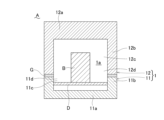
- the housing structure A includes a housing 1, which is divided into two parts, one housing 11 and the other housing 12.
- the one housing 11 and the other housing 12 are manufactured by a general-purpose resin molding method such as injection molding or blow molding.
- the one housing 11, the partition wall and heat dissipation fins 12h and 12i described below, and the other housing 12 that constitute the housing 1 are made of a heat dissipating resin, and the housing 1 has excellent heat conductivity.
- the heat dissipating resin is made by adding a heat conductive material that has a higher heat conductivity than the synthetic resin to a synthetic resin.
- heat conductive materials include heat conductive fine particles such as graphite, carbon black, and metal fine particles, and heat conductive fibers such as carbon fibers and metal fibers.
- the other housing 12 has a bottom 12a and a peripheral wall 12b integrally formed around the entire outer periphery of the bottom 12a.
- the other housing 12 has a space 12c formed in the area surrounded by the bottom 12a and the peripheral wall 12b, in which electronic components including a heat-generating component B can be placed and which has an opening 12d that is completely open.
- the frame-shaped edge of the peripheral wall portion 11b of the one side housing 11 and the frame-shaped edge of the peripheral wall portion 12b of the other side housing 12 are bonded together with adhesive G, so the housing structure has excellent lightness.
- the one side housing 11 and/or the other side housing 12 are formed with a cooling medium flow passage I for circulating a cooling medium (e.g., water, air, etc.) for cooling the one side housing 11 and/or the other side housing 12 as necessary.
- a cooling medium e.g., water, air, etc.
- the partition wall portion 12f and the bottom 12a do not separate from each other due to deformation caused by heat generated by the heat generating component B, and there is no decrease in heat transfer caused by the connection interface when heat is transferred from the partition wall portion 12f to the bottom 12a, and therefore the heat generated by the heat generating component B can be smoothly dissipated from the bottom 12a to the outside via the partition wall portion 12f.
- "there is no connection interface between two members” means that there is no adhesive or heat-sealed portion at the boundary between the two members when the two members are integrated together.
- connection interface between the partition wall 12f and the bottom 12a means that there is no adhesive or heat-sealed portion at the boundary between the partition wall 12f and the bottom 12a.
- the bottom 12a of the other housing 12 and the partition wall 12f integrated with the bottom 12a are simultaneously thermoformed by a resin molding process in which raw resin is thermoformed into a desired shape.
- the other housing 12 is molded by injection molding, raw resin is supplied into the cavity of a mold for molding the other housing 12, and the bottom 12a of the other housing 12 and the partition wall portion 12f integrated with the bottom 12a are simultaneously thermally formed, whereby the other housing 12 can be manufactured without there being a connection interface between the bottom 12a and the partition wall portion 12f.
- the inner surface of the partition wall portion 12f of the other housing 12 and the inner surface of the bottom portion 12a surrounded by this partition wall portion 12f form a heat generating component storage portion 12g that is fully open at the tip side and can partially or completely store a heat generating component B.
- This heat generating component storage portion 12g is formed to a size that can store a part or the whole of the heat generating component B arranged and fixed in the one housing 11.
- the shape of the partition wall portion 12f is not particularly limited.
- the shape of the partition wall portion 12f is appropriately adjusted to match the shape of the heat generating component B to be stored, and examples include a cylindrical shape (a rectangular cylindrical shape or a cylindrical shape). Adjacent partition wall portions 12f may be connected and integrated with each other by sharing a part of the partition wall portion.
- metal hydroxides include aluminum hydroxide and magnesium hydroxide.
- metal nitrides include aluminum nitride, silicon nitride, and boron nitride.
- Other metal powders such as aluminum and copper, as well as graphite and carbon fiber, can also be used as heat conductive fillers. Curable heat-conductive grease is preferred because it prevents leakage to the surrounding area.
- the thermal conductivity of the heat conductive grease is preferably 2.0 W/m ⁇ K or more, more preferably 3.0 W/m ⁇ K or more, and even more preferably 4.5 W/m ⁇ K or more.
- the thermal conductivity of the heat conductive grease is preferably 40.0 W/m ⁇ K or less.
- the thermal conductivity of the heat conductive grease is a value measured at 25°C using the laser flash method.
- the heat generated by the heat generating component B housed in the first heat generating component housing section 12g is dissipated to the outside through the bottom 12a of the other housing 12 via the thermally conductive grease F and the partition wall section 12f constituting the heat generating component housing section 12g, but it also flows out of the first partition wall section 12f through the gap section E formed between the first partition wall section 12f and the base material, and is dissipated to the outside through the bottom 12a of the other housing 12 via another partition wall section 12f arranged in the electronic component housing section 1a of the housing 1.
- the heat generated by the heat generating component B can be dissipated to the outside through multiple partition wall sections 12f, improving the cooling effect of the heat generating component B.
- heat-generating component B when heat-generating component B is disposed on printed wiring board D, an electrical circuit is formed on printed wiring board D.
- gap portion E is formed so that the tip of partition wall portion 12f does not reach printed wiring board D, the effect of heat transferred to partition wall portion 12f on printed wiring board D can be reduced, and printed wiring board D can be prevented from being damaged by heat generated by heat-generating component B.
- the partition wall portion 12f does not contact the printed wiring board D, there is no need to provide an area for the partition wall portion 12f to abut against the printed wiring board D, and by eliminating unnecessary parts from the printed wiring board D, the printed wiring board D can be made smaller, which in turn makes it possible to make the housing structure A smaller and lighter.
- a plurality of heat dissipation fins 12h are integrally provided on the inner surface of the bottom 12a portion surrounded by the inner surface of the partition wall portion 12f of the other side housing 12 toward the heat generating component storage portion 12g.
- the heat dissipation fins 12h are integrally provided on the entire inner surface of the bottom 12a portion surrounded by the inner surface of the partition wall portion 12f, and the heat dissipation fins 12h may be integrally provided on part of the inner surface.
- the heat dissipation fins 12h are provided on the inner surface of the bottom 12a during resin molding of the other side housing 12 and are integrally formed with the bottom 12a, and there is no connection interface between the heat dissipation fins 12h and the bottom 12a.
- the heat dissipation fins 12h are formed from a heat dissipating resin.
- Heat conductive grease F is also filled between the opposing surfaces of the plurality of heat dissipation fins 12h.
- the heat dissipation fins 12h and the bottom 12a do not separate from each other due to deformation caused by heat generated by the heat generating component B, and the heat transfer performance is not reduced due to the connection interface when heat is transferred from the heat dissipation fins 12h to the bottom 12a. Therefore, the heat generated by the heat generating component B is smoothly dissipated from the bottom 12a to the outside via the heat dissipation fins 12h and the heat conductive grease F. "There is no connection interface between the heat dissipation fins 12h and the bottom 12a" means that there is no adhesive part or heat fusion part at the boundary between the heat dissipation fins 12h and the bottom 12a.
- thermoform the bottom 12a of the other housing 12 and the heat dissipation fins 12h integrated with the bottom 12a by a resin molding process in which raw resin is thermoformed into a desired shape.
- a resin molding process in which raw resin is thermoformed into a desired shape.
- the other housing 12 is molded by injection molding, raw resin is supplied into the cavity of a mold for molding the other housing 12, and the bottom 12a of the other housing 12 and the heat dissipation fins 12h integrated with the bottom 12a are thermally formed at the same time, making it possible to manufacture the other housing 12 without there being a connection interface between the bottom 12a and the heat dissipation fins 12h.
- a plurality of heat dissipation fins 12i may be integrally provided on the outer surface of the housing 1 (preferably the outer surface of the other housing 12).
- the heat dissipation fins 12i are provided on the outer surface of the housing 1 (preferably the bottom 12a of the other housing 12) during resin molding of the housing 1 (preferably the other housing 12) and are integrally formed with the housing 1 (preferably the bottom 12a of the other housing 12), and there is no connection interface between the heat dissipation fins 12i and the housing 1 (preferably the bottom 12a of the other housing 12).
- the heat dissipation fins 12i are formed from a heat dissipating resin.
- the heat dissipation fins 12i and the housing 1 do not separate from each other due to deformation caused by heat generated by the heat generating component B, and there is no decrease in heat transfer caused by the connection interface when heat is transferred from the heat dissipation fins 12i to the housing 1, and therefore the heat generated by the heat generating component B can be more effectively dissipated to the outside from the heat dissipation fins 12i.
- "There is no connection interface between the heat dissipation fins 12i and the housing 1" means that there is no adhesive or heat fused portion at the boundary between the heat dissipation fins 12i and the housing 1.
- a resin molding process in which raw resin is thermoformed into a desired shape.
- raw resin is supplied into the cavity of a molding die for molding the housing 1, and the housing 1 and the heat dissipation fins 12i integrated with the housing 1 are thermoformed simultaneously, whereby the housing 1 can be manufactured without the presence of a connection interface between the housing 1 and the heat dissipation fins 12i.
- some of the heat dissipation fins 12i formed on the outer surface of the housing 1 are formed on the outer surface of the other housing 12 or the outer surface of the bottom 12a located on the opposite side of the partition wall portion 12f across the other housing 12 or its bottom 12a. It is preferable that the heat dissipation fins 12i are formed in a portion where the partition wall portion 12f is projected onto the outer surface of the housing 1 in the direction opposite to the direction in which it is formed. Heat generated from the heat-generating component B can be efficiently dissipated to the outside of the housing 1 via the partition wall portion 12f and the heat dissipation fins 12i.
- the other-side housing 12 is placed on any mounting surface H with the heat-generating component storage section 12g, which is formed by being surrounded by the partition wall section 12f, open upward.
- Fluid heat-conducting grease F is supplied into the heat-generating component storage section 12g of the other-side housing 12. If the heat-conducting grease F is normally solid, it is necessary to heat the heat-conducting grease F to make it fluid.
- a label such as a scale or step section is formed on the inner surface of the partition wall section 12f of the other-side housing 12 to indicate the required amount of heat-conducting grease F to be supplied, and the fluid heat-conducting grease F is supplied into the heat-generating component storage section 12g up to the required amount indicated on the label (grease supply process).
- the one-side housing 11 is turned upside down so that the opening 11d of the space 11c of the one-side housing 11 faces the opening 12d of the space 12c of the other-side housing 12. Then, the heat-generating components B of the one-side housing 11 are positioned above each heat-generating component housing section 12g of the other-side housing 12, and are embedded in the thermally conductive grease F inside the heat-generating component housing section 12g.
- the one side housing 11 is displaced in a direction approaching the other side housing 12 (downward) so that the frame-shaped edges of the peripheral wall portion 11b of the one side housing 11 and the frame-shaped edges of the peripheral wall portion 12b of the other side housing 12 are aligned around the entire circumference, and part or all of each heat-generating component B fixed to the one side housing 11 is embedded in the thermally conductive grease F in each heat-generating component accommodating portion 12g of the other side housing 12 (embedding process). Heat-generating components B are inserted from above and buried in the heat-conductive grease F stored in each heat-generating component storage section 12g of the other housing 12, making it easy to do.
- the heat-conductive grease F can be tightly packed into the space formed between at least the tip of the heat-generating component B and the opposing partition wall section 12f and bottom section 12a, allowing the heat generated by the heat-generating component B to be efficiently guided to the partition wall section 12f and bottom section 12a via the heat-conductive grease F and dissipated to the outside.
- Adhesive G is applied over the entire area between the opposing surfaces of the frame-shaped edge of the peripheral wall portion 11b of the one side housing 11 and the frame-shaped edge of the peripheral wall portion 12b of the other side housing 12, and the one side housing 11 and the other side housing 12 are integrated with adhesive G.
- the spaces 11c, 12c of the one side housing 11 and the other side housing 12 form an electronic component storage section 1a, and electronic components C including heat-generating components B are stored in this electronic component storage section 1a.
- each heat-generating component housing portion 12g of the other housing 12 is cooled, solidified, or cured to lose its fluidity and become solid (heat-conductive grease fixation process), and the heat-generating component B is fixed in a state where it is partially or entirely buried in the heat-conductive grease F, thereby producing the housing structure A.
- the housing structure A can be easily manufactured by simply supplying the heat-conductive grease F having fluidity into each heat-generating component housing portion 12g of the other housing 12, and then immersing part or all of the heat-generating components B arranged and fixed to the one housing 11 from above into this heat-conductive grease.
- the housing structure A can smoothly dissipate heat generated by the heat-generating component B to the outside of the housing 1, protecting the electronic component C disposed within the housing 1 from heat and enabling the electronic component C to operate stably.
- the housing structure A is lightweight, it can be used by accommodating a power conversion device or the like and mounting it on an electric vehicle or the like.
- Example 1 5 one housing 11 was prepared, which had a bottom 11a and a peripheral wall 11b integrally formed around the entire outer periphery of the bottom 11a.
- the one housing 11 had a space 11c in the area surrounded by the bottom 11a and the peripheral wall 11b, in which electronic components including a heat-generating component B could be disposed and which had an opening 11d that was completely open.
- One housing 11 was composed of a heat dissipating resin (thermal conductivity: 12.3 W/m ⁇ K) containing 100 parts by mass of polypropylene (manufactured by Japan Polypropylene Corporation, product name "BC10HRF"), 100 parts by mass of expanded graphite (manufactured by Fuji Graphite Industries Co., Ltd., product name "EXP-80S220", expansion ratio: 200 mL/g, volume average particle size: 180 ⁇ m), and 100 parts by mass of flake graphite (manufactured by Chuetsu Graphite Industries Co., Ltd., product name "CPB-100", volume average particle size: 100 ⁇ m).
- a heat dissipating resin thermo conductivity: 12.3 W/m ⁇ K
- Another-side housing 12 was prepared, which had a bottom 12a and a peripheral wall 12b integrally formed around the entire outer periphery of the bottom 12a.
- the other-side housing 12 had a space 12c formed in the area surrounded by the bottom 12a and the peripheral wall 12b, in which electronic components including a heat-generating component B could be placed and which had an opening 12d that was completely open.
- the other-side housing 12 was made of the same heat-dissipating resin as the one-side housing 11.
- the spaces 11c, 12c of the one-side housing 11 and the other-side housing 12 are closed, and the spaces 11c, 12c of the one-side housing 11 and the other-side housing 12 form an electronic component storage section 1a capable of storing electronic components.
- the frame-shaped edges of the peripheral wall section 11b of the one-side housing 11 and the frame-shaped edges of the peripheral wall section 12b of the other-side housing 12 are bonded together with adhesive G.
- the one-side housing 11 and the other-side housing 12 form the housing 1.
- Heat-generating component B was disposed and fixed in space 11c of one housing 11. Heat-generating component B was fixed on printed wiring board D.
- a single cylindrical partition wall portion 12f was integrally provided on the inner surface of bottom 12a of the other housing 12, protruding in the direction of heat-generating component B disposed and fixed to one housing 11 and partially surrounding heat-generating component B.
- Partition wall portion 12f of the other housing 12 was provided protruding from bottom 12a during resin molding of the other housing 12 and was formed integrally with bottom 12a, with no connection interface being present between partition wall portion 12f and bottom 12a.
- Partition wall portion 12f was made of the same heat-dissipating resin as one housing 11.
- the heat generating component accommodating portion 12g of the other housing 12 accommodates part or all of the heat generating component B disposed and fixed in the space portion 11c of the one housing 11.
- a number of heat dissipation fins 12h were integrally provided on the inner surface of the bottom 12a portion surrounded by the inner surface of the partition wall portion 12f of the other-side housing 12, protruding toward the inside of the heat-generating component storage portion 12g.
- the heat dissipation fins 12h were made of the same heat dissipation resin as the one-side housing 11. There was no connection interface between the heat dissipation fins 12h and the bottom 12a.
- the heat dissipation fins 12h were made of the same heat dissipation resin as the other-side housing 12.
- a plurality of heat dissipation fins 12i were integrally provided on the outer surface of the other-side housing 12.
- the heat dissipation fins 12i were provided on the outer surface of the bottom 12a during resin molding of the other-side housing 12 and were formed integrally with the bottom 12a, and there was no connection interface between the heat dissipation fins 12i and the bottom 12a.
- the heat dissipation fins 12i were made of the same heat dissipating resin as the other-side housing 12.
- Some of the heat dissipation fins 12i were formed on the outer surface of the bottom 12a on the opposite side of the bottom 12a of the other-side housing 12 from the partition wall portion 12f. In detail, some of the heat dissipation fins 12i were formed in the portion where the partition wall portion 12f was projected onto the outer surface of the housing 1 in the opposite direction to its formation direction (upward in FIG. 5).
- the heat generating component B of the housing structure A ( Figure 5) constructed as described above was driven.
- the temperature T of the surface of the heat generating component B was measured 10 minutes after the heat generating component B was driven.
- the temperature T is shown in Table 1.
- Example 2 A housing structure A (FIG. 6) was prepared, which had the same structure as the housing structure of Example 1, except that the heat dissipation fins 12h were not formed on the inner surface of the bottom 12a of the other housing 12 and the inner surface of the bottom 12a was formed into a smooth surface.
- the heat generating component B of the housing structure A was driven.
- the temperature T of the surface of the heat generating component B was measured 10 minutes after the heat generating component B was driven.
- the temperature T is shown in Table 1.
- Example 3 A housing structure A (FIG. 7) was prepared, which had the same structure as the housing structure of Example 1, except that no heat dissipation fins 12i were formed on the outer surface of the bottom 12a of the other housing 12 and the outer surface of the bottom 12a was formed as a flat surface.
- the heat generating component B of the housing structure A was driven.
- the temperature T of the surface of the heat generating component B was measured 10 minutes after the heat generating component B was driven.
- the temperature T is shown in Table 1.
- Example 4 A housing structure A (FIG. 8) was prepared, which had the same structure as the housing structure of Example 1, except that the heat dissipation fins 12h, 12i were not formed on the inner and outer surfaces of the bottom 12a of the other housing 12 and the inner and outer surfaces of the bottom 12a were formed into flat surfaces.
- the heat generating component B of the housing structure A was driven.
- the temperature T of the surface of the heat generating component B was measured 10 minutes after the heat generating component B was driven.
- the temperature T is shown in Table 1.
- FIG. 9 A housing structure A (FIG. 9) was prepared, which had the same structure as the housing structure of Example 4, except that no partition wall was formed on the inner surface of the bottom 12a of the other housing 12, and no thermally conductive grease was used. An air layer was formed in the space formed between the inner surface of the housing 1 and the heat-generating component B, and the housing 1 and the heat-generating component B were not in contact with each other. The heat-generating component B of the housing structure A was driven. The temperature T of the surface of the heat-generating component B was measured 10 minutes after the heat-generating component B was driven. The temperature T is shown in Table 1.
- the housing structure of the present invention allows the heat generated by the heat-generating components to be effectively dissipated to the outside through the partition wall and the housing via the thermally conductive grease, and is also lightweight, making it suitable for use in power conversion devices used in electric vehicles.
- Case 1a Electronic component housing 11 One side housing 11a Bottom 11b Peripheral wall 11c Space 11d Opening 12 Other side housing 12a Bottom 12b Peripheral wall 12c Space 12d Opening 12th floor Partition wall 12g Heat generating component housing 12h Heat sink fin A Housing structure B Heat generating components C Electronic components D Printed wiring board E Gap F Thermally conductive grease G Adhesive
Landscapes
- Engineering & Computer Science (AREA)
- Microelectronics & Electronic Packaging (AREA)
- Physics & Mathematics (AREA)
- Thermal Sciences (AREA)
- Cooling Or The Like Of Electrical Apparatus (AREA)
- Cooling Or The Like Of Semiconductors Or Solid State Devices (AREA)
Abstract
Description
放熱性樹脂を含む筐体と、
上記筐体内に収容された発熱部品と、
上記筐体の内面に上記発熱部品に向かって樹脂成形によって一体的に形成され且つ上記発熱部品を包囲する仕切壁部と、
上記仕切壁部と上記筐体とによって囲まれた部分から構成され且つ上記発熱部品を収容可能な発熱部品収容部と、
上記発熱部品収容部内において、上記発熱部品と上記仕切壁部との対向面間に介在している伝熱性グリースとを有することを特徴とする。
放熱性樹脂を含む筐体と、
上記筐体内に収容された発熱部品とを備え、
上記筐体は、その内面に上記発熱部品に向かって樹脂成形によって一体的に形成されて上記発熱部品を包囲する仕切壁部を有し、
上記仕切壁部と上記筐体とによって囲まれた部分を上記発熱部品を収容可能な発熱部品収容部としており、上記発熱部品収容部において、上記発熱部品と上記仕切壁部との対向面間には伝熱性グリースが介在されていることを特徴とする。
放熱性樹脂を含み且つ開口部を有する一側筐体に発熱部品を配設、固定する発熱部品配設工程と、
開口部を有し、内底面に樹脂成形によって仕切壁部が一体的に形成され且つ放熱性樹脂を含む他側筐体における上記仕切壁部及び上記仕切壁部によって包囲された他側筐体部分によって形成された発熱部品収容部内に流動性を有する伝熱性グリースを供給するグリース供給工程と、
上記他側筐体の発熱部品収容部内に上記一側筐体に配設、固定した上記発熱部品を挿入し、上記他側筐体の発熱部品収容部内の伝熱性グリースに上記一側筐体の上記発熱部品の少なくとも一部を埋没させる埋没工程と、
上記伝熱性グリースを固化又は硬化させる伝熱性グリース固定化工程とを含むことを特徴とする。
図5に示したように、底部11aとこの底部11aの外周縁部にその全周に亘って一体的に形成された周壁部11bとを有する一側筐体11を用意した。一側筐体11は、底部11a及び周壁部11bとで囲まれた部分に発熱部品Bを含む電子部品を配設可能で且つ全面的に開口した開口部11dを有する空間部11cが形成されていた。一側筐体11は、ポリプロピレン(日本ポリプロ社製 商品名「BC10HRF」)100質量部、膨張黒鉛(富士黒鉛工業社製 商品名「EXP-80S220」、膨張倍率:200mL/g、体積平均粒子径:180μm)100質量部及び鱗片状黒鉛(中越黒鉛工業所社製 商品名「CPB-100」、体積平均粒子径:100μm)100質量部を含む放熱性樹脂(熱伝導率:12.3W/m・K)から構成されていた。
他側筐体12の底部12aの内面に放熱フィン12hが形成されず且つ底部12aの内面が平滑面に形成されていること以外は、実施例1の筐体構造と同様の構造を有する筐体構造A(図6)を用意した。筐体構造Aの発熱部品Bを駆動させた。発熱部品Bを駆動させてから10分経過後の発熱部品B表面の温度Tを測定した。温度Tを表1に示した。
他側筐体12の底部12aの外面に放熱フィン12iが形成されず且つ底部12aの外面が平坦面に形成されていること以外は、実施例1の筐体構造と同様の構造を有する筐体構造A(図7)を用意した。筐体構造Aの発熱部品Bを駆動させた。発熱部品Bを駆動させてから10分経過後の発熱部品B表面の温度Tを測定した。温度Tを表1に示した。
他側筐体12の底部12aの内面及び外面に放熱フィン12h、12iが形成されず且つ底部12aの内面及び外面が平坦面に形成されていること以外は、実施例1の筐体構造と同様の構造を有する筐体構造A(図8)を用意した。筐体構造Aの発熱部品Bを駆動させた。発熱部品Bを駆動させてから10分経過後の発熱部品B表面の温度Tを測定した。温度Tを表1に示した。
他側筐体12の底部12aの内面に仕切壁部を形成せず、且つ伝熱性グリースを用いなかったこと以外は、実施例4の筐体構造と同様の構造を有する筐体構造A(図9)を用意した。筐体1の内面と発熱部品Bとの間に形成された空間部には、空気層が形成されており、筐体1と発熱部品Bとは接触していなかった。筐体構造Aの発熱部品Bを駆動させた。発熱部品Bを駆動させてから10分経過後の発熱部品B表面の温度Tを測定した。温度Tを表1に示した。

本出願は、2023年6月26日に出願された日本国特許出願第2023-104542号に基づく優先権を主張し、この出願の開示はこれらの全体を参照することにより本明細書に組み込まれる。
1a 電子部品収容部
11 一側筐体
11a 底部
11b 周壁部
11c 空間部
11d 開口部
12 他側筐体
12a 底部
12b 周壁部
12c 空間部
12d 開口部
12f 仕切壁部
12g 発熱部品収容部
12h 放熱フィン
A 筐体構造
B 発熱部品
C 電子部品
D プリント配線板
E 隙間部
F 伝熱性グリース
G 接着剤
Claims (15)
- 放熱性樹脂を含む筐体と、
上記筐体内に収容された発熱部品と、
上記筐体の内面に上記発熱部品に向かって樹脂成形によって一体的に形成され且つ上記発熱部品を包囲する仕切壁部と、
上記仕切壁部と上記筐体とによって囲まれた部分から構成され且つ上記発熱部品を収容可能な発熱部品収容部と、
上記発熱部品収容部内において、上記発熱部品と上記仕切壁部との対向面間に介在している伝熱性グリースとを有することを特徴とする筐体構造。 - 上記発熱部品収容部において、上記発熱部品と上記発熱部品に対向する上記筐体との対向面間には伝熱性グリースが介在されていることを特徴とする請求項1に記載の筐体構造。
- 発熱部材は、プリント配線板上に配設されていることを特徴とする請求項1又は請求項2に記載の筐体構造。
- 上記仕切壁部と上記仕切壁部に対向する上記プリント配線板との間に隙間部が形成されていることを特徴とする請求項3に記載の筐体構造。
- 上記発熱部品収容部の内面に、樹脂成形によって一体的に形成された放熱フィンを有することを特徴とする請求項1又は請求項2に記載の筐体構造。
- 上記放熱フィン間に配設された伝熱性グリースを有することを特徴とする請求項5に記載の筐体構造。
- 上記筐体は、二分割された一側筐体と他側筐体とを含み、上記一側筐体の開口部と上記他側筐体の開口部とを突き合わせ状態にて一体化して構成され、上記一側筐体の開口端部と上記他側筐体の開口端部とが接着剤によって一体化されていることを特徴とする請求項1に記載の筐体構造。
- 発熱部品は、リアクトル、トランス、コイル及びコンデンサからなる群から選ばれた少なくとも一の発熱部品であることを特徴とする請求項1又は請求項2に記載の筐体構造。
- 上記仕切壁部をその形成方向とは反対側に投影した筐体の外面部分に、放熱フィンが形成されていることを特徴とする請求項1又は請求項2に記載の筐体構造。
- 放熱性樹脂を含み且つ開口部を有する一側筐体に発熱部品を配設、固定する発熱部品配設工程と、
開口部を有し、内底面に樹脂成形によって仕切壁部が一体的に形成され且つ放熱性樹脂を含む他側筐体における上記仕切壁部及び上記仕切壁部によって包囲された他側筐体部分によって形成された発熱部品収容部内に流動性を有する伝熱性グリースを供給するグリース供給工程と、
上記他側筐体の発熱部品収容部内に上記一側筐体に配設、固定した上記発熱部品を挿入し、上記他側筐体の発熱部品収容部内の伝熱性グリースに上記一側筐体の上記発熱部品の少なくとも一部を埋没させる埋没工程と、
上記伝熱性グリースを固化又は硬化させる伝熱性グリース固定化工程とを含むことを特徴とする筐体構造の製造方法。 - 上記発熱部品収容部の内面に、樹脂成形によって一体的に形成された放熱フィンを有することを特徴とする請求項10に記載の筐体構造の製造方法。
- 上記埋没工程は、
上記他側筐体をその発熱部品収容部の開口部が上方に向かって開口した状態に載置面上に載置する工程と、
上記他側筐体の上方において、上記一側筐体に配設した上記発熱部品が上記他側筐体の発熱部品収容部の開口部に対向した状態となるように配設する工程と、
上記一側筐体と上記他側筐体とを互いに近接させて、上記他側筐体の発熱部品収容部内に上記一側筐体に配設、固定した上記発熱部品を挿入し、上記他側筐体の発熱部品収容部内の伝熱性グリース内に上記一側筐体内の上記発熱部品の少なくとも一部を埋没させる工程とを含むことを特徴とする請求項10又は請求項11に記載の筐体構造の製造方法。 - 上記一側筐体の開口端部と上記他側筐体の開口端部とをその全周に亘って接着剤によって一体化する接着工程を有することを特徴とする請求項10又は請求項11に記載の筐体構造の製造方法。
- 上記他側筐体の仕切壁部の内面に、流動性を有する伝熱性グリースの供給必要量を示すためのラベルが形成されていることを特徴とする請求項10又は請求項11に記載の筐体構造の製造方法。
- ラベルが、仕切壁部の内面に設けられた目盛又は段差であることを特徴とする請求項14に記載の筐体構造の製造方法。
Priority Applications (3)
| Application Number | Priority Date | Filing Date | Title |
|---|---|---|---|
| JP2025530140A JPWO2025005087A1 (ja) | 2023-06-26 | 2024-06-25 | |
| CN202480036922.XA CN121241664A (zh) | 2023-06-26 | 2024-06-25 | 壳体结构及其制造方法 |
| EP24831947.7A EP4734681A1 (en) | 2023-06-26 | 2024-06-25 | Housing structure and method for manufacturing same |
Applications Claiming Priority (2)
| Application Number | Priority Date | Filing Date | Title |
|---|---|---|---|
| JP2023104542 | 2023-06-26 | ||
| JP2023-104542 | 2023-06-26 |
Publications (1)
| Publication Number | Publication Date |
|---|---|
| WO2025005087A1 true WO2025005087A1 (ja) | 2025-01-02 |
Family
ID=93939085
Family Applications (1)
| Application Number | Title | Priority Date | Filing Date |
|---|---|---|---|
| PCT/JP2024/023015 Ceased WO2025005087A1 (ja) | 2023-06-26 | 2024-06-25 | 筐体構造及びその製造方法 |
Country Status (4)
| Country | Link |
|---|---|
| EP (1) | EP4734681A1 (ja) |
| JP (1) | JPWO2025005087A1 (ja) |
| CN (1) | CN121241664A (ja) |
| WO (1) | WO2025005087A1 (ja) |
Citations (10)
| Publication number | Priority date | Publication date | Assignee | Title |
|---|---|---|---|---|
| JP2009054701A (ja) * | 2007-08-24 | 2009-03-12 | Hitachi Kokusai Electric Inc | 電子部品放熱構造 |
| JP2012079741A (ja) * | 2010-09-30 | 2012-04-19 | Denso Corp | 電子制御ユニット |
| WO2014046004A1 (ja) * | 2012-09-21 | 2014-03-27 | 日立オートモティブシステムズ株式会社 | 電子制御装置 |
| JP2015089179A (ja) | 2013-10-29 | 2015-05-07 | 三菱電機株式会社 | 電力変換装置 |
| WO2019220485A1 (ja) * | 2018-05-14 | 2019-11-21 | 三菱電機株式会社 | 電力変換装置 |
| WO2021245983A1 (ja) * | 2020-06-05 | 2021-12-09 | 日立Astemo株式会社 | 車載電子制御装置 |
| WO2022004183A1 (ja) * | 2020-07-01 | 2022-01-06 | 日立Astemo株式会社 | 電子制御装置 |
| WO2022091596A1 (ja) * | 2020-10-27 | 2022-05-05 | 日立Astemo株式会社 | 電子制御装置 |
| WO2022224537A1 (ja) * | 2021-04-20 | 2022-10-27 | 日立Astemo株式会社 | 車載装置 |
| JP2023104542A (ja) | 2022-01-18 | 2023-07-28 | 矢崎総業株式会社 | 接続端子 |
-
2024
- 2024-06-25 JP JP2025530140A patent/JPWO2025005087A1/ja active Pending
- 2024-06-25 EP EP24831947.7A patent/EP4734681A1/en active Pending
- 2024-06-25 CN CN202480036922.XA patent/CN121241664A/zh active Pending
- 2024-06-25 WO PCT/JP2024/023015 patent/WO2025005087A1/ja not_active Ceased
Patent Citations (10)
| Publication number | Priority date | Publication date | Assignee | Title |
|---|---|---|---|---|
| JP2009054701A (ja) * | 2007-08-24 | 2009-03-12 | Hitachi Kokusai Electric Inc | 電子部品放熱構造 |
| JP2012079741A (ja) * | 2010-09-30 | 2012-04-19 | Denso Corp | 電子制御ユニット |
| WO2014046004A1 (ja) * | 2012-09-21 | 2014-03-27 | 日立オートモティブシステムズ株式会社 | 電子制御装置 |
| JP2015089179A (ja) | 2013-10-29 | 2015-05-07 | 三菱電機株式会社 | 電力変換装置 |
| WO2019220485A1 (ja) * | 2018-05-14 | 2019-11-21 | 三菱電機株式会社 | 電力変換装置 |
| WO2021245983A1 (ja) * | 2020-06-05 | 2021-12-09 | 日立Astemo株式会社 | 車載電子制御装置 |
| WO2022004183A1 (ja) * | 2020-07-01 | 2022-01-06 | 日立Astemo株式会社 | 電子制御装置 |
| WO2022091596A1 (ja) * | 2020-10-27 | 2022-05-05 | 日立Astemo株式会社 | 電子制御装置 |
| WO2022224537A1 (ja) * | 2021-04-20 | 2022-10-27 | 日立Astemo株式会社 | 車載装置 |
| JP2023104542A (ja) | 2022-01-18 | 2023-07-28 | 矢崎総業株式会社 | 接続端子 |
Also Published As
| Publication number | Publication date |
|---|---|
| JPWO2025005087A1 (ja) | 2025-01-02 |
| CN121241664A (zh) | 2025-12-30 |
| EP4734681A1 (en) | 2026-04-29 |
Similar Documents
| Publication | Publication Date | Title |
|---|---|---|
| TWI377465B (en) | Heat dissipating module and electronic device using such heat dissipating module | |
| CN101632142B (zh) | 壳体模制式电容器及其使用方法 | |
| US8203839B2 (en) | Cooling devices, power modules, and vehicles incorporating the same | |
| CN108886184B (zh) | 散热模块及利用其的电动汽车用电池组 | |
| US20130181667A1 (en) | Contactless power supply device | |
| JP5267181B2 (ja) | リアクトル | |
| CN106915264A (zh) | 用于电动车辆的车载充电器 | |
| JP5640507B2 (ja) | リアクトル装置 | |
| JP5664472B2 (ja) | 電力変換装置 | |
| CN106561076A (zh) | 具有导热界面材料的逆变器及应用其的混合动力车 | |
| CN105810400A (zh) | 用于变压器的冷却装置 | |
| KR20150060558A (ko) | 파워 전환 장치 및 그의 조립 방법 | |
| JP7483963B2 (ja) | 電源装置 | |
| CN110786083B (zh) | 用于电动或混合动力汽车的电子电力设备以及相关实现方法 | |
| US20120147565A1 (en) | Heat dissipation and temperature-homogenizing structure and electronic device having the same | |
| JP4937326B2 (ja) | パワーモジュール | |
| JP2012009499A (ja) | 車両用コンデンサ | |
| CN219555487U (zh) | 逆变器设备和包括该逆变器设备的汽车牵引电机设备 | |
| CN114079390A (zh) | 功率转换装置 | |
| CN113439492B (zh) | 电动汽车用功率半导体冷却模块 | |
| WO2024239818A1 (zh) | 散热装置及电子设备 | |
| JP2022146794A (ja) | インサート製品及びその製造方法 | |
| KR20230147407A (ko) | 방열 구조를 갖는 차량용 컨버터 | |
| EP4734681A1 (en) | Housing structure and method for manufacturing same | |
| JP7504294B2 (ja) | 電子機器 |
Legal Events
| Date | Code | Title | Description |
|---|---|---|---|
| 121 | Ep: the epo has been informed by wipo that ep was designated in this application |
Ref document number: 24831947 Country of ref document: EP Kind code of ref document: A1 |
|
| ENP | Entry into the national phase |
Ref document number: 2025530140 Country of ref document: JP Kind code of ref document: A |
|
| WWE | Wipo information: entry into national phase |
Ref document number: 2025530140 Country of ref document: JP |
|
| ENP | Entry into the national phase |
Ref document number: 2024831947 Country of ref document: EP Effective date: 20260126 |
|
| WWE | Wipo information: entry into national phase |
Ref document number: 2024831947 Country of ref document: EP |
|
| NENP | Non-entry into the national phase |
Ref country code: DE |
|
| ENP | Entry into the national phase |
Ref document number: 2024831947 Country of ref document: EP Effective date: 20260126 |
|
| ENP | Entry into the national phase |
Ref document number: 2024831947 Country of ref document: EP Effective date: 20260126 |
|
| WWP | Wipo information: published in national office |
Ref document number: 2024831947 Country of ref document: EP |