WO2025004910A1 - 金属製加工品の製造方法及び金属製加工品 - Google Patents
金属製加工品の製造方法及び金属製加工品 Download PDFInfo
- Publication number
- WO2025004910A1 WO2025004910A1 PCT/JP2024/022099 JP2024022099W WO2025004910A1 WO 2025004910 A1 WO2025004910 A1 WO 2025004910A1 JP 2024022099 W JP2024022099 W JP 2024022099W WO 2025004910 A1 WO2025004910 A1 WO 2025004910A1
- Authority
- WO
- WIPO (PCT)
- Prior art keywords
- die
- cutting
- coining
- punch
- cut end
- Prior art date
- Legal status (The legal status is an assumption and is not a legal conclusion. Google has not performed a legal analysis and makes no representation as to the accuracy of the status listed.)
- Ceased
Links
Images


Classifications
-
- B—PERFORMING OPERATIONS; TRANSPORTING
- B21—MECHANICAL METAL-WORKING WITHOUT ESSENTIALLY REMOVING MATERIAL; PUNCHING METAL
- B21D—WORKING OR PROCESSING OF SHEET METAL OR METAL TUBES, RODS OR PROFILES WITHOUT ESSENTIALLY REMOVING MATERIAL; PUNCHING METAL
- B21D28/00—Shaping by press-cutting; Perforating
- B21D28/02—Punching blanks or articles with or without obtaining scrap; Notching
- B21D28/16—Shoulder or burr prevention, e.g. fine-blanking
-
- B—PERFORMING OPERATIONS; TRANSPORTING
- B21—MECHANICAL METAL-WORKING WITHOUT ESSENTIALLY REMOVING MATERIAL; PUNCHING METAL
- B21D—WORKING OR PROCESSING OF SHEET METAL OR METAL TUBES, RODS OR PROFILES WITHOUT ESSENTIALLY REMOVING MATERIAL; PUNCHING METAL
- B21D22/00—Shaping without cutting, by stamping, spinning, or deep-drawing
- B21D22/02—Stamping using rigid devices or tools
-
- B—PERFORMING OPERATIONS; TRANSPORTING
- B21—MECHANICAL METAL-WORKING WITHOUT ESSENTIALLY REMOVING MATERIAL; PUNCHING METAL
- B21D—WORKING OR PROCESSING OF SHEET METAL OR METAL TUBES, RODS OR PROFILES WITHOUT ESSENTIALLY REMOVING MATERIAL; PUNCHING METAL
- B21D28/00—Shaping by press-cutting; Perforating
- B21D28/02—Punching blanks or articles with or without obtaining scrap; Notching
-
- B—PERFORMING OPERATIONS; TRANSPORTING
- B21—MECHANICAL METAL-WORKING WITHOUT ESSENTIALLY REMOVING MATERIAL; PUNCHING METAL
- B21D—WORKING OR PROCESSING OF SHEET METAL OR METAL TUBES, RODS OR PROFILES WITHOUT ESSENTIALLY REMOVING MATERIAL; PUNCHING METAL
- B21D35/00—Combined processes according to or processes combined with methods covered by groups B21D1/00 - B21D31/00
- B21D35/001—Shaping combined with punching, e.g. stamping and perforating
Definitions
- the present invention relates to a method for manufacturing a metal processed product using a plated metal sheet having a plating layer on the surface as a raw material, with cut ends aligned in the thickness direction of the raw material, and with coining surfaces formed on the corners of the cut ends, and to the metal processed product.
- metal processed products made from plated metal sheets with a plating layer on the surface are increasingly being used as parts for devices such as automobiles and home appliances.
- plated metal sheets as the material, it is possible to omit the plating process after forming the metal processed product, thereby reducing manufacturing costs.
- Omitting the plating process after forming it is possible to avoid deterioration of the dimensional accuracy of the parts due to the plating process after forming. Omitting the plating process after forming is particularly considered for parts that require high dimensional accuracy, such as motor cases.
- Patent Document 1 a method of removing rust from cut ends is proposed in which half-cutting (half-punching) is performed with a negative clearance using a punch and die with an R-shaped cutting edge in the first step, and in the second step, an R is given only to the die (or punch), and finish cutting is performed with a positive clearance, so that the plating layer on the surface wraps around the end face of the cut end.
- Patent Document 1 also discloses that coining is performed following the finish cutting step. In coining, a smoothed surface is formed on the corners on the fractured surface side of the cut end of the processed product after finish cutting. The smoothed surface is less likely to develop red rust than the fractured surface, which is a newly formed rough surface. In addition, coining can crush burrs that occur during finish cutting. Coining is performed by sandwiching the cut end between a pad with a pressing surface and a coining block, and compressing the corners on the fractured surface side with the pressing surface.
- the inventors are considering making more of the plating layer wrap around the end face of the cut end in order to increase the rust prevention effect.
- the radius of curvature of the cutting edge of the punch and die used in semi-cutting is increased, and the amount of depression of the die is increased.
- a new problem arises in that a protrusion called a horn is generated on the bottom of the cut end in the finish cutting process, and after the coining process, a large protrusion originating from the horn is formed on the underside of the cut end. The protrusion is formed when the horn is crushed by the coining process.
- Patent Document 1 does not take these issues into consideration.
- drawn products such as motor cases are often provided with flanges for fixing the product to other equipment.
- the ends of the flanges are formed by cutting. If a large protrusion is formed on the underside of the flange, a space will be created between the flange and other equipment when the flange is fixed to the other equipment, causing rattling and raising concerns that this could lead to a deterioration in product performance.
- the present invention has been made to solve the above problems, and one of its objectives is to provide a manufacturing method for metal processed products that can reduce the height of the protrusions resulting from the horns that remain after the coining process. Another objective of the present invention is to provide a metal processed product that can reduce rattling caused by the protrusions.
- a manufacturing method for a metal processed product according to the present invention is a manufacturing method for a metal processed product using a plated metal sheet having a plating layer on a surface thereof as a raw material, the metal processed product having a cut edge along the thickness direction of the raw material and a coining surface formed on a corner portion of the cut edge, the manufacturing method for a metal processed product comprising: a half-cutting step using a first die and a first punch to half-cut a first element formed from the raw material in the thickness direction to form a half-cut portion; a finish-cutting step using a second die and a second punch to finish-cut the half-cut portion in the same direction as the half-cutting to obtain a second element having a cut edge; and a coining step to press a corner portion of the cut edge of the second element against a pad to obtain a metal processed product having a coining surface formed on the corner portion.
- the clearance C 31-41 (mm) between the first die and the first punch is set to a negative clearance
- the cutting edge of the first die and the cutting edge of the first punch are R-shaped with predetermined radii of curvature R D1 and R P1 (mm)
- a horn having a height h (mm) is formed in the half-cut portion, and the height h (mm) corresponds to the distance between a position on the cutting edge of the first punch on an extension line of the side surface of the first die and an extension line of the upper surface of the first punch that contacts the lower surface of the first body, along the pressing direction of the first die, and is expressed by the following formula:
- the pad has a vertical wall surface, a bottom wall surface, and a flat or curved pressing surface that connects the vertical wall surface and the bottom wall surface at a corner where the vertical wall surface and the bottom wall surface meet, and against which the corner portion of the cut end portion is pressed;
- the metal processed product according to the present invention is a metal processed product whose material is a plated metal sheet having a plating layer on its surface, and has a cut end along the thickness direction of the material, the cut end having a sag, a sheared surface, and a coining surface in that order in the thickness direction of the cut end from the upper surface side to the lower surface side, the sheared surface having a first sheared surface that is continuous with the sag and a second sheared surface that is continuous with the first sheared surface in the thickness direction, the inclination angle ⁇ d1 of the first sheared surface with respect to the thickness direction of the sheet and the inclination angle ⁇ d2 of the second sheared surface with respect to the thickness direction of the sheet satisfy ⁇ d1> ⁇ d2, the sheared surface is longer than the remaining length L1 (mm) of the plating component covered by the surface plating layer and the cut The ratio L1/t1 to the thickness t1 (mm) of the end is 0.
- the height of the protrusions resulting from the horns remaining after the coining process can be reduced.
- rattling caused by the protrusions can be reduced.
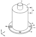
- FIG. 1 is a perspective view showing an example of a metal processed product manufactured by a method for manufacturing a metal processed product according to an embodiment of the present invention
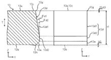
- FIG. 2 is an explanatory diagram showing a first aspect of a cut end portion in region A of FIG. 1 .
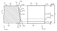
- 2 is an explanatory diagram showing a second aspect of the cut end portion in region A of FIG. 1 .
- FIG. FIG. 2 is an explanatory diagram showing a third aspect of the cut end portion in region A of FIG. 1 .
- FIG. 2 is an explanatory diagram showing a fourth aspect of the cut end portion in region A of FIG. 1 .
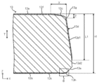
- FIG. 3 is a detailed cross-sectional view of the cut end of FIG. 2 .
- FIG. 7 is a detailed view of area B in FIG.
- FIG. 6; 13 is a graph showing an example of the relationship between sagging Z and sagging X.
- 1 is an explanatory diagram showing a method for manufacturing a metal processed product according to an embodiment of the present invention
- FIG. 10 is an explanatory diagram showing a first die and a first punch used in the half-cutting step of FIG. 9
- FIG. 11 is an explanatory diagram showing an enlarged view of a half-cut portion of FIG. 10
- 11 is an explanatory diagram showing a change in a horn portion due to a change in the radius of curvature of the cutting edge of the first punch in FIG. 10 and a change in the clearance.
- FIG. FIG. 10 is an explanatory diagram showing a second die and a second punch used in the finish cutting step of FIG.
- FIG. 10 is an explanatory diagram showing a pad and a coining block used in the coining process of FIG. 1 is a photograph showing the cut edge of a metal workpiece after a coining process.
- FIG. 2 is a perspective view showing an example of a processed product.
- FIG. 11 is a perspective view showing another example of a processed product.
- FIG. 11 is a perspective view showing another example of a processed product.
- FIG. 11 is a perspective view showing another example of a processed product.
- FIG. 17 is a schematic diagram showing an example of a cutting die for manufacturing the processed product of FIG. 16 .
- 21 is a schematic diagram showing a state in which an element body has been punched using the cutting die of FIG. 20.
- FIG. 17 is a schematic diagram showing an example of a coining die for manufacturing the processed product of FIG. 16 .
- FIG. 11 is a perspective view showing another example of a processed product.
- 1 is a graph showing the relationship between the height of the horn portion after semi-cutting (before finish cutting) and the coining area of a pad used in the coining process in the examples.
- Fig. 1 is a perspective view showing an example of a metal processed product 1 manufactured by a manufacturing method for a metal processed product 1 according to an embodiment of the present invention.
- the metal processed product 1 shown in Fig. 1 is a motor case made of a plated metal sheet having a plating layer on its surface.
- the motor case shown in Fig. 1 can be formed by subjecting a flat plated metal sheet to a forming process such as drawing.
- the metal processed product 1 in this embodiment has a body portion 10, a protrusion portion 11, and a flange portion 12.
- the body 10 has a hollow cylindrical side wall 101 and a top wall 103 formed to cover one end of the side wall 101.
- the top wall 103 may be called something else, such as a bottom wall, depending on the orientation in which the metal processed product 1 is used.
- the cross-sectional shape of the body 10 of the metal processed product 1 shown in FIG. 1 in the XY plane (the transverse cross-sectional shape of the body 10) is a perfect circle, but the present invention is not limited to this example.
- the cross-sectional shape of the body 10 in the XY plane may be other shapes, such as an ellipse or a polygon.
- the protrusion 11 is a protruding body that protrudes from the top wall 103 to the outside in the central axis direction (Z direction) of the body 10. Note that the protrusion 11 does not necessarily have to be formed, and the top wall 103 may be flat.
- the flange portion 12 is a plate portion that extends from an end of the body portion 10 (i.e., the other end of the side wall 101) toward the outside in the radial direction (X and Y directions) of the body portion 10.
- the shape of the flange portion 12 is arbitrary.
- the flange portion 12 in this embodiment extends in the radial direction of the body portion 10 over the entire circumferential area of the body portion 10.
- the flange portion 12 has a plurality of screw holes 121 spaced apart from each other in the circumferential direction of the body portion 10. Screws 123 are inserted into the screw holes 121.
- the metal processed product 1 can be fixed to an attachment object, such as a vehicle body, by fastening it to the attachment object using the screws 123.
- the flange portion 12 in this embodiment is formed by cutting a flange portion base body (first flange portion base body 20 in FIG. 9) that has an outer diameter larger than the outer diameter of the flange portion 12 that will ultimately be formed in the metal processed product 1.
- the metal processed product 1 in this embodiment has a cut end portion 13 on the outer periphery of the flange portion 12. The cut end portion 13 is aligned along the sheet thickness direction of the plated metal sheet that is the material.
- Cutting processes include processes such as shearing, punching, and drilling.
- Cutting is a process in which the object to be cut is cut along a specified straight line or curve.
- Punching is a process in which a product is punched out of the object to be cut.
- Drilling is a process in which a non-product part is punched out of the object to be cut, resulting in a product with an opening.
- the flange portion 12 shown in Figure 1 can be obtained by punching out the flange portion base body.
- the base material of the plated metal sheet may be any metal, such as steel, copper, a copper alloy, aluminum, or an aluminum alloy.
- the plated metal sheet is a plated steel sheet.
- the manufacturing method of the metal processed product 1 according to the embodiment of the present invention described later is particularly suitable when the base material is steel. This is because steel rusts easily, and the advantage of imparting corrosion resistance is great.
- the plated steel sheet is, for example, a Zn-based plated steel sheet, an Al-based plated steel sheet, etc.
- the plated steel sheet is more preferably a Zn-based plated steel sheet.
- Zn-based plating has a sacrificial corrosion protection effect on the base material steel sheet. Therefore, it is possible to suppress corrosion from the exposed base material part of the end face of the cut end portion 13, and the corrosion resistance of the manufactured metal member can be further improved.
- Examples of Zn-based plating include hot-dip Zn zinc plating, alloyed hot-dip galvanizing, Zn-Ni plating, Zn-Al plating, Zn-Mg plating, Zn-Al-Mg plating, etc.
- the thickness of the plated metal sheet is not particularly limited.
- the thickness of the plated metal sheet can be, for example, 0.8 mm or more and 6.0 mm or less, more preferably 2.0 mm or more and 4.5 mm or less.
- a preferred lower limit of the plating weight is 30 g/ m2 .
- a more preferred lower limit of the plating weight is 45 g/ m2 .
- a preferred upper limit of the plating weight is 450 g/ m2 .
- a more preferred upper limit of the plating weight is 190 g/ m2 .
- Figs. 2 to 5 are explanatory diagrams showing first to fourth aspects of the cut end 13 in region A in Fig. 1.
- the left side of Figs. 2 to 5 is a cross-sectional view of the cut end 13 in the ZX plane in Fig. 1, and the right side of Figs. 2 to 5 is a front view of the cut end 13 as viewed along the X direction in Fig. 1.
- Fig. 6 is a detailed cross-sectional view of the cut end 13 in Fig. 2
- Fig. 7 is a detailed view of region B in Fig. 6.
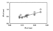
- FIG 8 is a graph showing an example of the relationship between sagging Z and sagging X.
- the plate thickness direction T of the cut end 13 is the same direction as the central axis direction (Z direction) of the metal processed product 1 shown in Fig. 1.
- the plating layers 13f and 13k shown in Fig. 6 are omitted.
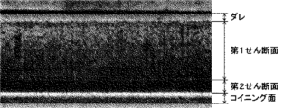
- the cut end 13 has a sag 13c, a shear surface 13d, and a coining surface 13e in that order in the thickness direction T of the cut end 13 from the upper surface 13a to the lower surface 13b.
- the upper surface 13a is the surface (pushed surface) into which the cutting edge of the cutting die (first die 31 and second die 32 in Figs. 10 and 13) is pressed when cutting the flange portion body.
- the lower surface 13b is the surface from which the cutting edge of the cutting die emerges when cutting the flange portion body.
- the sagging 13c is a portion of the flange body surface deformed by a tensile force acting on the surface of the flange body (the plated metal sheet material) when the cutting edge of the cutting die is pressed into the flange body.
- the sagging 13c typically appears on the cut end 13 as a smooth surface with a curvature.
- the dimension of the sagging 13c in the thickness direction T of the cut end 13 is referred to as "sagging Z”
- the dimension of the sagging 13c in the planar direction perpendicular to the thickness direction T is referred to as "sagging X”.
- the sheared surface 13d is the surface where the flange portion body has been sheared by the cutting edge of the cutting die.
- the sheared surface 13d is adjacent to the sag 13c in the plate thickness direction T of the cut end 13.
- the sheared surface 13d typically appears as a smooth surface at the cut end 13.
- the sheared surface 13d may have a metallic luster because it is created when the cutting die comes into contact with the workpiece and then a compressive (pressure) force is applied, causing it to bite into the workpiece and rub against the side of the cutting die.
- the sheared surface 13d may have fine streak-like sliding marks in the plate thickness direction T.
- the coining surface 13e is a surface formed by pressing or compressing the corner portion 13m (see FIG. 9) on the lower surface 13b side of the cut end portion 13 by the coining process described later.
- the coining surface 13e is a tapered surface (flat chamfered surface).
- the inclination angle ⁇ of the extension direction of the coining surface 13e with respect to the extension direction of the lower surface 13b can be, for example, 45° or 60°.
- the coining surface 13e may be another pressed or compressed surface such as an R surface (curved chamfered surface).
- the coining surface 13e typically appears on the cut end portion 13 as a smooth surface in which the unevenness of the fracture surface has been smoothed.
- the cut end portion 13 does not need to have a burr. This is because even if a burr occurs during the cutting process, the burr is crushed by the coining process.
- methods for identifying the sagging 13c, shear surface 13d, and coining surface 13e include, for example, observing and measuring the shape profile of the cut end 13 from the outside using a microscope or a contrast tracer based on the above characteristics.
- the shear surface 13d in this embodiment has a first shear surface 13d1 that is continuous with the sag 13c in the thickness direction T, and a second shear surface 13d2 that is continuous with the first shear surface 13d1.
- the lower end of the second shear surface 13d2 may be continuous with the coining surface 13e.
- the first shear surface 13d1 and the second shear surface 13d2 are surfaces with different inclination angles ⁇ d1 and ⁇ d2 with respect to the thickness direction T.
- the inclination angle ⁇ d1 of the first shear surface 13d1 with respect to the thickness direction T and the inclination angle ⁇ d2 of the second shear surface 13d2 with respect to the thickness direction T satisfy ⁇ d1> ⁇ d2.
- the first shear surface 13d1 is inclined more than the second shear surface 13d2 with respect to the thickness direction T.
- a boundary line may be visible between the first shear surface 13d1 and the second shear surface 13d2.
- the second shear surface 13d2 may protrude outward more than the first shear surface 13d1.
- the plating layer 13f wraps around the sheared surface 13d from the upper surface 13a of the cut end portion 13.
- the plating layer 13f is stretched by the cutting die and wraps around the sheared surface 13d. This wrapping around of the plating layer 13f causes at least a portion of the sheared surface 13d to be covered with the plating layer 13f, making it possible to suppress the occurrence of red rust in the portion covered with the plating layer 13f.
- the sacrificial anticorrosive action of the Zn-based plating layer can also suppress the occurrence of red rust in the vicinity of the portion covered with the plating layer 13f.
- the length L1 of the plating layer 13f covering at least a part of the sagging 13c and the sheared surface 13d from the upper surface 13a of the cut end 13 is 0.80 times or more the thickness t1 of the cut end 13 of the metal processed product 1.
- the ratio L1/t1 of the remaining plating component length L1 where the sheared surface 13d is covered by the plating layer 13f on the surface of the plated metal plate to the thickness t1 of the cut end 13 is 0.80 or more.
- the length L1 of the plating layer 13f or the remaining plating component length L1 can also be said to be the distance between the upper surface 13a of the cut end 13 in the thickness direction T of the cut end 13 and the lower end of the plating layer 13f.
- the thickness t1 of the cut end 13 can also be said to be the distance between the upper surface 13a and the lower surface 13b of the cut end 13 in the thickness direction T of the cut end 13. More specifically, the thickness t1 of the cut end 13 may be the distance between the upper surface 13a and the lower surface 13b at a position not affected by the sag 13c and the coining surface 13e (a position sufficiently distant from the outer edge of the cut end 13).
- the thickness t1 of the cut end 13 is equal to the thickness of the flange portion 12 shown in FIG. 1.
- a pressing or compressive force acts on the cut end 13 from the lower surface 13b side toward the upper surface 13a side of the cut end 13, and the sagging 13c, shear surface 13d, and fracture surface may be pushed up within the cut end 13.
- the sagging 13c of the cut end 13 may take the form shown in Figure 3 or Figure 4, rather than the form shown in Figure 2.
- FIG. 3 shows an embodiment in which the boundary position 13g between the sag 13c and the sheared surface 13d has been pushed up to the same height as the upper surface 13a by the coining process.
- FIG. 4 shows an embodiment in which the boundary position 13g between the sag 13c and the sheared surface 13d has been pushed up to a higher position than the upper surface 13a by the coining process.
- a deformed surface corresponding to the sag 13c remains following the smooth upper surface 13a of the cut end portion 13.
- the deformed surface may bulge upward from the smooth upper surface 13a.
- such a deformed surface is also treated as the sag 13c.
- the sag 13c as shown in FIG. 4 may also be referred to as an upwardly convex sag 13c.
- the ratio Z/t1 of the length Z of the sagging 13c in the plate thickness direction T from the upper surface 13a of the cut end 13 toward the lower surface 13b of the cut end 13 to the plate thickness t1 of the cut end 13 is set to be -0.10 or more and less than 0.10.
- the ratio Z/t1 By making the ratio Z/t1 less than 0.10, it is possible to prevent the sagging X (the dimension of the sagging 13c in a planar direction perpendicular to the plate thickness direction T) from becoming too large. It is more preferable that the ratio Z/t1 is 0 or more and less than 0.10. This makes it possible to make the shape of the cut end 13 more preferable.
- the ratio Z/t1 may be -0.10 or more and less than 0.
- Figure 8 shows an example of the relationship between sagging Z and sagging X of the cut end 13 when punching is performed in one process.
- Figure 8 shows the relationship between sagging Z and sagging X of the cut end 13 of the product when punching is performed by giving a radius of curvature of 0.01 to 0.30 in relation to the plate thickness of the flange portion plate to the cutting edge of the cutting die that is pressed into the flange portion plate, and setting the clearance of the cutting die to 0.01 to 0.20 times the plate thickness.
- the sagging X that appears in the planar direction is about 3 to 4 times larger than the sagging Z in the plate thickness direction. This correlation is before the coining process, but it also has an effect after the coining process.
- the height position of the top surface 13a of the cut end 13 is set as the reference position (0 point), and the length from the top surface 13a to a position below the top surface 13a is defined as a positive length, and the length from the top surface 13a to a position above the top surface 13a is defined as a negative length.
- the reference position is the height position of the top surface 13a of the cut end 13 at a position that is not affected by the sagging 13c and coining surface 13e (a position sufficiently distant from the outer edge of the cut end 13).
- the measurement points of the height position on the surface of the cut end 13 can be scanned from a position not affected by the sag 13c and the coining surface 13e toward the outer edge of the cut end 13.
- the boundary position 13g is at a position lower than the upper surface 13a as in the first embodiment shown in FIG. 2
- the height position of the surface of the cut end 13 gradually decreases toward the boundary position 13g, and the height position of the surface of the cut end 13 takes a discontinuous value when the boundary position 13g is exceeded.
- the boundary position 13g is at the same height as the upper surface 13a as in the second embodiment shown in FIG.
- the height position of the surface of the cut end 13 slightly changes toward the boundary position 13g, and the height position of the surface of the cut end 13 takes a discontinuous value when the boundary position 13g is exceeded.
- the boundary position 13g is at a position higher than the upper surface 13a as in the third embodiment shown in FIG. 4, the height position of the surface of the cut end 13 gradually increases toward the boundary position 13g, and the height position of the surface of the cut end 13 takes a discontinuous value when the boundary position 13g is exceeded.
- the length Z of the sagging 13c can be the length in the plate thickness direction T between the height position just before the height position of the surface of the cut end 13 becomes discontinuous and the reference position.
- the height position just before the height position of the surface of the cut end 13 becomes discontinuous can be the height position of the boundary position 13g.
- the length Z of the sagging 13c can be measured by observing the shape profile of the cut end 13 using a contrast tracer or the like.
- a protrusion 13h is provided on the lower part of the coining surface 13e.
- the protrusion 13h is formed by the material of the corner part 13m (see FIG. 9) on the lower surface 13b side of the cut end part 13 escaping inward in a direction perpendicular to the plate thickness direction T (the X-axis direction in the figure) during the coining process that forms the coining surface 13e.
- the protrusion 13h has a height h0 greater than 0 mm and less than or equal to 0.20 mm.
- the metal processed product 1 may be used such that the lower surface 13b of the cut end 13 is in contact with another structure. If the height h0 of the protrusion 13h is large, a space will be created between the lower surface 13b of the cut end 13 and the other structure, causing wobble. By setting the height h0 of the protrusion 13h to 0.20 mm or less, wobble caused by the protrusion 13h can be reduced.
- the height h0 may be the distance between the lower surface 13b of the cut end 13 and the lower end of the protrusion 13h in the plate thickness direction T of the cut end 13.
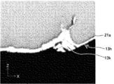
- protrusion 13h may be formed when horn 21a (horn-shaped protrusion) created by cutting is crushed by coining, and the plating layer 13k on the underside 13b of the cut end 13 may become wrapped up in protrusion 13h.
- the amount of plating layer 13k wrapped around protrusion 13h can be reduced, and the occurrence of whisker burrs caused by the falling off of this plating layer 13k can be suppressed.
- the plating layer 13k on the surface of the plated metal sheet wraps around from the underside 13b of the cut end 13 to the end face of the cut end 13.
- the plating layer 13k on the underside 13b is pressed or compressed together with the portion that constitutes the coining surface 13e, and wraps around to the end face of the cut end 13.
- This wrapping around of the plating layer 13k causes at least a portion of the coining surface 13e to be covered with the plating layer 13k. In the portion of the coining surface 13e that is covered with the plating layer 13k, the occurrence of red rust can be further suppressed.
- the height Lc of the upper end of the plating layer 13k that wraps around from the lower surface 13b of the cut end 13 in the plate thickness direction T based on the lower surface 13b of the cut end 13 is 0.10 times or more the radius of curvature R0 or the tapered surface height C0 of the coining surface 13e.
- the radius of curvature R0 is the radius of curvature of the outer surface of the coining surface 13e when the coining surface 13e is an R surface (a curved chamfered surface) as shown in FIG. 5.
- the tapered surface height C0 is the length between the lower surface 13b and the upper end of the coining surface 13e along the plate thickness direction T when the coining surface 13e is a tapered surface (a flat chamfered surface) as shown in FIG. 2, etc.
- These curvature radii R0 and tapered surface heights C0 can be measured on the cross section of the cut end 13.
- Fig. 9 is an explanatory diagram showing a manufacturing method of the metal processed product 1 according to the embodiment of the present invention.
- the manufacturing method of the metal processed product 1 according to the embodiment of the present invention includes a preparation step, a semi-cutting step, a finish cutting step, and a coining step.
- the preparation process is a process of preparing the first body 2.
- the first body 2 can be obtained by performing forming processing such as drawing on a flat plated metal plate. That is, the first body 2 is made of a plated metal plate, like the metal processed product 1.
- the first body 2 has a first flange body 20 having an outer diameter larger than the flange 12 shown in FIG. 1.
- the first flange body 20 may have a circular or non-circular outer shape in a plan view.
- the first body 2 may have a shape similar to that of the metal processed product 1 except for the first flange body 20.
- the preparation process does not have to involve forming the plated metal strip.
- a body processed by a third party by some method may be obtained.
- the first flange body 20 of this embodiment constitutes the flat cut portion including the portion that will become the cut end 13.
- the half-cutting process is a process for half-cutting the first body 2.
- the first flange body 20 (the portion to be cut) is half-cut.
- Half-cutting is a process for cutting the first flange body 20 to a midpoint in the plate thickness direction of the first flange body 20.
- the smooth surface smoothed by the die used for half-cutting (side surface 31a of first die 31 in FIG. 10) becomes the first shear surface 13d1.
- the removed portion 20a which will ultimately be outside the product, is cut partway off from the first flange body 20.
- the finishing cutting process is a process in which the first flange body 20 (the portion to be cut) of the first body 2 is cut to obtain the second body 3.
- the second body 3 is an intermediate member for manufacturing the metal processed product 1, and the metal processed product 1 can be obtained by further processing the second body 3.
- the removed portion 20a of the first flange body 20 is cut and separated from the first flange body 20.
- the second flange body 30 is formed by cutting the removed portion 20a.
- the smooth surface smoothed by the side of the die used for finishing cutting (side surface 32a of the second die 32 in FIG. 13) becomes the second shear surface 13d2.
- the second flange body 30 has a cut end 13.
- the cut end 13 of the second body 3 has a corner portion 13m on the lower surface 13b side.
- the corner portion 13m may have burrs and/or a horn portion 21a (see FIG. 13, etc.) described below.
- the coining process is a process for obtaining the metal processed product 1 by coining the cut end 13 of the second element 3 obtained in the finish cutting process.
- the coining process in this embodiment is a process for pressing the corner portion 13m of the cut end portion 13 of the second element 3 against the pad 7 to form a coining surface 13e on the corner portion 13m.
- the coining surface 13e is a surface where the corner portion 13m is crushed.
- the coining surface 13e is formed on the corner portion 13m of the second flange portion element 30 of the second element 3, thereby obtaining the metal processed product 1 having the flange portion 12.
- the screw holes 121 of the metal processed product 1 shown in FIG. 1 may be formed in the first flange portion element 20 or the second flange portion element 30 at the stage of the first element 2 or the second element 3, or may be formed in the flange portion 12 after the coining process.
- the first flange portion body 20 and the second flange portion body 30 are machined using a die and a punch. Details of the semi-cutting process and the finish-cutting process are described below. The cutting edges of the die and the punch are sometimes referred to as "shoulders.”
- the die used to obtain the metal processed product 1 will be referred to as the die on the pushing side and the die on the side being pushed in as the punch.
- the die on the pushing side may be located above or below the blanks 2 and 3.
- the die on the pushing side will be referred to as the die and the die on the side being pushed in as the punch.
- the metal processed product 1 shown in FIG. 2 was cut using the upper die as the pushing side die. If the lower die is the pushing side die, that is, if the lower die is the die, the cut end 13 of the metal processed product 1 will have the sag 13c located at the bottom of the cut end 13, as opposed to FIG.
- the shear surface 13d and coining surface 13e will be formed above it. If it is unclear which die (top or bottom, or left or right) will be the die or punch, it is sufficient to actually perform cutting, observe the cut end 13, and refer to the die that presses the surface on the side where the sag 13c is located as the die, and the die that presses the opposite surface as the punch.
- the upper surface 13a of the cut end portion 13 is defined as the surface on the side where the cutting edge of the die is pressed in during cutting of the first flange portion body 20 and the second flange portion body 30, i.e., the surface on the side where the sag 13c is located.
- the lower surface 13b of the cut end portion 13 is defined as the surface on the side where the cutting edge of the die comes out during cutting of the second flange portion body 30.
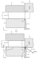
- Fig. 10 is an explanatory diagram showing the first die 31 and the first punch 41 used in the half-cutting step of Fig. 9.
- Fig. 11 is an explanatory diagram showing an enlarged view of the half-cutting portion 21 of Fig. 10.
- Fig. 12 is an explanatory diagram showing the change in the horn portion 21a due to the change in the radius of curvature R P1 of the cutting edge of the first punch 41 and the clearance C 31-41 of Fig. 10.
- FIG. 10 shows the state immediately before the half-cutting process, and the lower part of FIG. 10 shows the state immediately after the half-cutting process.
- the first body 2 is half-cut in the plate thickness direction using the first die 31 and the first punch 41 to form the half-cut portion 21.
- FIG. 10 shows, as one aspect of the half-cutting process, an aspect in which the first flange portion body 20 of the first body 2 clamped by the first punch 41 and the first plate holder 51 is half-cut (half-punched).
- the first die 31 constitutes a cutting die that is pressed into the first flange portion body 20 during half-cutting.
- the die that presses the portion of the first flange portion body 20 that will become the flange portion 12 is the first punch 41
- the die that presses the removed portion 20a is the first die 31.
- the clearance C 31-41 (mm) between the first die 31 and the first punch 41 is a negative clearance.
- the clearance C 31-41 represents the gap between the first die 31 and the first punch 41, and is specifically represented by the distance between the side surface 31a of the first die 31 and the side surface 41a of the first punch 41, as shown in FIG. 10.
- the clearance in a state where there is no clearance i.e., when C 31-41 is zero
- the clearance in a state where the first die 31 and the first punch 41 are separated from each other as viewed from the pushing direction of the first die 31 i.e., the plate thickness direction of the flange portion 12, the Z direction
- the clearance in a state where the first die 31 and the first punch 41 partially overlap each other is called a negative clearance.
- the clearance between the die and the punch is represented by a positive value for the positive clearance and a negative value for the negative clearance.
- the first die 31 and the first punch 41 for semi-cutting the first body 2 are arranged so that the first die 31 and the first punch 41 partially overlap when viewed from the pushing direction of the first die 31.
- the clearance C 31-41 is a positive clearance
- cracks generated from the cutting edges of the first die 31 and the first punch 41 may meet as in a one-time punching process, and the removed portion 20a may be completely cut off from the first flange portion body 20.
- the sagging 13c of the cut end portion 13 will increase.
- the clearance C 31-41 to a negative clearance, it is possible to prevent the removed portion 20a from being completely cut off from the first flange portion body 20 in the semi-cutting step and reduce the sagging 13c.
- the clearance C 31-41 a negative clearance, a large hydrostatic stress occurs in the region sandwiched between the first die 31 and the first punch 41. Therefore, the ratio of the tensile stress occurring between the material that will become scrap (i.e., the removed portion 20a) after cutting and the flange material that will become the flange portion 12 in the stress occurring when the first die 31 is pressed into the first flange portion element 20 decreases. As a result, the material that contacts the tip of the blade of the first die 31 that will become scrap after cutting is more likely to flow from the tip of the blade of the first die 31 to the side 31a of the first die 31, and the wrapping of the plating layer 13f around the sheared surface 13d can be increased.
- the clearance C 31-41 [mm] between the first die 31 and the first punch 41 satisfies the following formula (a1). -0.35 ⁇ t1 ⁇ C 31-41 ⁇ -0.0125 ⁇ t1...(a1)
- t1 is the plate thickness (mm) of the portion to be partially cut of the first body 2.
- the portion to be partially cut of the first body 2 is the first flange portion body 20.
- the clearance C 31-41 is ⁇ 0.0125 times or less the thickness t1 of the first flange element 20 a large hydrostatic stress is generated in the region sandwiched by the first die 31 and the first punch 41, and the proportion of tensile stress is reduced. As a result, cracks are generated during half-cutting, causing complete cutting, and large fracture surfaces are not generated, and it is possible to avoid the removal portion 20a being completely cut from the first flange element 20 in the half-cutting process. On the other hand, if the clearance C 31-41 is ⁇ 0.35 times or more the thickness t1 of the first flange element 20, the forming load required for half-cutting does not increase and does not exceed the press capacity.
- the clearance C 31-41 is ⁇ 0.10 times or less or ⁇ 0.15 times or less the thickness t1 of the first flange element 20.
- the clearance C 31-41 may be set to be ⁇ 0.30 times or more, or ⁇ 0.25 times or more, the plate thickness t 1 of the first flange portion body 20 .
- the cutting edge of the first die 31 and the cutting edge of the first punch 41 are rounded with predetermined radii of curvature R D1 and R P1 (mm) as shown in FIG.
- the radius of curvature R D1 (mm) of the cutting edge of the first die 31 satisfies the following formula (a2). 0.10 ⁇ t1 ⁇ R D1 ⁇ 1.50 (a2) It is preferable that the radius of curvature R P1 (mm) of the cutting edge of the first punch 41 satisfies the following formula (a3). 0.10 ⁇ t1 ⁇ R P1 ⁇ 3.00 (a3)
- radius of curvature R D1 is 0.10 times the plate thickness t1 or more, a large hydrostatic stress is generated under a negative clearance without scraping off the plating layer 13f, and the material to become the scrap (i.e., the removed portion 20a) directly below the first die 31 can flow from the cutting edge of the first die 31 to the side surface 31a of the first die 31.
- R p1 is 0.10 times the plate thickness t1 or more, the first die 31 can be pressed deeper into the first flange portion element 20, so that the material to become the scrap (i.e., the removed portion 20a) directly below the first die 31 can flow from the cutting edge of the first die 31 to the side surface 31a of the first die 31.
- the proportion of the tensile stress generated between the material to become the scrap after cutting and the flange material to become the flange portion 12 in the stress generated when the first die 31 is pressed into the first flange portion element 20 decreases.
- the plating layer 13f can be made to wrap around the shear surface 13d.
- the radius of curvature R D1 is 1.50 mm or less, less material is positioned at the cutting edge of the first die 31 during half-cutting, and the generation of fracture surfaces in the subsequent finish-cutting can be reduced. Furthermore, if the radius of curvature R P1 is 3.00 mm or less, it is possible to prevent the occurrence of whisker burrs, which are the falling off of the plating layer after the subsequent coining process, and an increase in the height h0 of the protrusion 13h resulting from the horn portion at the bottom of the coining surface 13e.
- the amount of the first flange portion body 20 cut in the semi-cutting process can be increased compared to when only one of the cutting edges of the first die 31 or the first punch 41 is R-shaped.
- the plate thickness t2 (mm) of the semi-cut portion 21 of the first body 2 can be reduced compared to when only one of the cutting edges of the first die 31 or the first punch 41 is R-shaped.
- the plate thickness t2 of the half-cut portion 21 of the first body 2 corresponds to the distance in the pressing direction of the first die 31 between the connection position of the cutting edge of the first die 31 and the side surface 31a and the upper surface 41b of the cutting edge of the first punch 41 that contacts the lower surface 2b of the first body 2 when the first die 31 is pressed down to the bottom dead center as shown in the lower side of Figure 10, and can also be said to be the remaining plate thickness of the removed portion 20a in the half-cut portion 21.
- the cutting edge of the first die 31 will come into contact with the cutting edge of the first punch 41 if the pushing amount D of the first die 31 is set to be greater than or equal to the thickness t1 of the flange portion 12. In this case, the pushing amount D of the first die 31 cannot be set to be greater than or equal to the thickness t1 of the flange portion 12.
- the pushing amount D is the amount of movement of the first die 31 from the position where the first die 31 contacts the top surface of the first flange portion body 20 of the first body 2 to the position where the pushing of the first die 31 stops (hereinafter, this position is also referred to as the "bottom dead center"), as shown in FIG. 10.
- the cutting edges of the first die 31 and the first punch 41 are R-shaped, as shown in FIG. 10, the amount by which the first die 31 can be pushed in until the cutting edge of the first die 31 contacts the cutting edge of the first punch 41 increases. Therefore, by making both the cutting edges of the first die 31 and the first punch 41 R-shaped, the pushing amount D of the first die 31 can be made equal to or greater than the plate thickness t1 of the flange portion 12, making it possible to increase the amount of cutting of the first flange portion body 20 in half-cutting, and increasing the proportion of the sheared surface 13d in the cut end portion 13.
- the plating layer 13f wrap around the sheared surface 13d more, and the proportion of the cut end portion 13 covered by the plating layer 13f can be increased.
- the remaining plate thickness t2 is reduced, so that the amount of cutting in the finish cutting process is reduced, and it is possible to avoid a state in which no plating layer remains in a part of the finish-cut portion.
- the remaining plate thickness t2 may be 0.30 times or less the plate thickness t1 [mm] of the first flange portion body 20.
- the pressing amount D (mm) of the first die 31 against the half-cut portion 21 (first flange portion body 20) satisfies the following formula (a4). 1.00 ⁇ t1 ⁇ D ⁇ t1+1.00 (a4) It is preferable that the distance C D1-P1 (mm) between the first die 31 and the first punch 41 at the bottom dead center satisfies the following formula (a5). 0.20 ⁇ C D1-P1 ...(a5)
- the amount of depression D is greater than 1.00 times the plate thickness t1, it is difficult for a fracture surface to be generated in the subsequent finish cutting.
- the amount of depression D is equal to or less than the plate thickness t1 plus 1.00 mm, the height h of the horn portion 21a can be reduced. This makes it easier to prevent the occurrence of whisker burrs, which are the loss of the plating layer after the coining process, and also makes it easier to keep the height h0 of the protrusion 13h at the bottom of the coining surface 13e to 0.20 mm or less.
- the distance C D1-P1 between the first die 31 and the first punch 41 at the bottom dead point is 0.20 mm or more, it is possible to prevent cracks from occurring during partial cutting, which may result in partial complete cutting.
- the distance C D1-P1 is the minimum distance between the first die 31 and the first punch 41 at the bottom dead point.
- a horn 21a having a height h (mm) is formed in the half-cut portion 21.
- the height h (mm) corresponds to the distance along the pushing direction of the first die 31 between a position on the cutting edge of the first punch 41 on an extension line of the side surface 31a of the first die 31 and an extension line of the upper surface 41b of the first punch 41 that contacts the lower surface 2b of the first body 2, and is expressed by the following formula. That is, the height h (mm) of the horn 21a is determined by the radius of curvature R P1 (mm) of the cutting edge of the first punch 41 used in the half-cutting step and the clearance C 31-41 (mm) between the first die 31 and the first punch 41.
- ) 2 +X 2 ...(1) By solving equation (1) for X, the following equation (2) is obtained. Here, h R P1 ⁇ X, so by substituting X into equation (2), the above equation for height h is obtained.
- Fig. 12(b) shows a schematic diagram of the horn portion 21a when the radius of curvature R P1 of the blade tip of the first punch 41 is larger than that of Fig. 12(a)
- Fig. 12(c) shows a schematic diagram of the horn portion 21a when the radius of curvature R P1 of the blade tip of the first punch 41 is larger than that of Fig. 12(a) and the clearance C 31-41 approaches a positive clearance.
- Figs. 12(b) shows a schematic diagram of the horn portion 21a when the radius of curvature R P1 of the blade tip of the first punch 41 is larger than that of Fig. 12(a) and the clearance C 31-41 approaches a positive clearance.
- Fig. 13 is an explanatory diagram showing the second die 32 and the second punch 42 used in the finish cutting step of Fig. 9.
- the upper side of Fig. 13 shows the state immediately before the finish cutting process, and the lower side of Fig. 13 shows the state immediately after the finish cutting process.
- the first flange element 20 having the half-cut portion 21 is finish-cut using the second die 32 and the second punch 42.
- FIG. 13 shows, as one mode of finish cutting, a mode in which the second flange element 30 is punched out from the first flange element 20 clamped by the second punch 42 and the second plate holder 52.
- the second die 32 constitutes a cutting die that is pressed into the first flange element 20 in the finish cutting.
- the die that presses the portion of the first flange element 20 that will become the flange portion 12 is the second punch 42
- the die that presses the removed portion 20a is the second die 32.
- the second die 32 may be the same as the first die 31.
- the first die 31 used in the half-cutting process may be used as the second die 32 in the finish cutting process.
- the positional relationship between the second die 32 and the first body 2 is preferably the same as the positional relationship between the first die 31 and the first body 2. If these positional relationships are not the same, for example, if the diameter of the second die 32 is larger than the diameter of the first die 31, a step will occur in the cut end 13. Conversely, for example, if the diameter of the second die 32 is smaller than the diameter of the first die 31, the second die 32 may come into contact with the half-cut cut end 13 generated in the half-cutting process, and the second die 32 may scrape off the plating layer 13f that has wrapped around the sheared surface 13d. Regarding the positional relationship between the second punch 42 and the first body 2, it is preferable that the diameter of the second punch 42 is smaller than the diameter of the first die 31.
- the diameter of the second punch 42 is smaller than the diameter of the second die 32, there is no problem even if the diameter of the second punch 42 is the same as the diameter of the first die 31. Conversely, if the diameter of the second punch 42 is larger than the diameter of the first die 31, a step will occur in the cut end 13.
- the finish cutting in this embodiment is performed from the same direction as the half cutting. That is, when the first die 31 is pressed into the first flange portion body 20 from the top side of the first flange portion body 20 in the half cutting as shown in FIG. 10, the second die 32 is also pressed into the first flange portion body 20 from the top side of the first flange portion body 20 in the finish cutting as shown in FIG. 13. This separates the removed portion 20a from the first flange portion body 20, and obtains the second body 3 having the cut end portion 13.
- the clearance C 32-42 [mm] between the second die 32 and the second punch 42 is a positive clearance.
- the clearance C 32-42 is expressed as the distance between the side surface 32a of the second die 32 and the side surface 42a of the second punch 42.
- the clearance when the second die 32 and the second punch 42 are separated from each other is called a positive clearance
- the clearance when the second die 32 and the second punch 42 are partially overlapped is called a negative clearance.
- the clearance C 32-42 (mm) between the second die 32 and the second punch 42 is a positive clearance. It is preferable that the clearance C 32-42 between the second die 32 and the second punch 42 satisfies the following formula (b1). 0.01 ⁇ C 32-42 ⁇ 0.20 ⁇ t2...(b1)
- t2 is the plate thickness of the semi-cut portion 21 of the first body 2 (first flange portion body 20) as described above, and corresponds to the distance along the pressing direction of the first die 31 between the connection position of the cutting edge of the first die 31 and the side surface 31a and the upper surface 41b of the cutting edge of the first punch 41 that contacts the lower surface 2b of the first body 2 when the first die 31 is pressed down to the bottom dead center as shown in the lower side of Figure 10, and can also be said to be the remaining plate thickness of the removed portion 20a in the semi-cut portion 21.
- the clearance C 32-42 is 0.01 mm or more, there is no risk of damage due to contact between the second die 32 and the second punch 42 even if the sliding accuracy of the press machine or the core misalignment of the die occurs during finish cutting. On the other hand, if the clearance C 32-42 is 0.20 times the plate thickness t2 or less, burrs are unlikely to be generated. Here, the smooth surface of the end surface smoothed by the side surface 32a of the second die 32 becomes the second shear surface 13d2.
- the cutting edge of the second die 32 is R-shaped with a predetermined radius of curvature R D2 (mm). As shown in FIG. 13, the second die 32 is pressed into the portion of the first flange portion body 20 where the finish cutting is performed, so the cutting edge of the second die 32 is R-shaped with a radius of curvature R D2 .
- the cutting edge of the second punch 42 is rectangular with no roundness as shown in FIG. 13. In this case, the cutting edge of the second punch 42 may have a radius of curvature of less than 0.25 mm, less than 0.15 mm, less than 0.10 mm, or less than 0.05 mm.
- the radius of curvature of the cutting edge of the second punch 42 may be less than 0.10 times the plate thickness t1 of the first flange portion body 20 of the first body 2, and may be less than 0.06 times, less than 0.04 times, or less than 0.02 times as necessary.
- the radius of curvature R D2 (mm) of the cutting edge of the second die 32 satisfies the following formula (b2). 0.25 ⁇ R D2 ⁇ 1.50 ⁇ t2 ... (b2) If the radius of curvature R D2 is 0.25 mm or more, the plating layer 13f that has wrapped around the sheared surface 13d is not scraped off by the second die 32. On the other hand, if the radius of curvature R D2 is 1.50 times the sheet thickness t2 or less, burrs are less likely to be generated.
- the inner diameter D32 of the second die 32 is set to be equal to or larger than the inner diameter D31 of the first die 31, and when the cut end 13 is formed on the inner periphery of the metal workpiece 1, the outer diameter d32 of the second die 32 is set to be equal to or smaller than the outer diameter d31 of the first die 31.
- of the difference between the inner diameter D31 of the first die 31 and the inner diameter D32 of the second die 32 is preferably 1.00 mm or less.
- of the difference between the outer diameter d31 of the first die 31 and the outer diameter d32 of the second die 32 is preferably 1.00 mm or less. This allows the step that occurs at the cut end 13 of the metal workpiece 1 due to the diameter difference D32-D31 or d32-d31 between the dies 31 and 32, which is required to perform two processes, the semi-cutting process and the finish cutting process, to be reduced, resulting in a good cut cross section.
- when the cut end 13 is formed on the inner periphery side of the metal workpiece 1 may be greater than 1.00 mm.
- are preferably smaller, and may be 0.75 mm, 0.50 mm, 0.35 mm, or 0.20 mm.
- is 0 mm.
- the step generated in the cut end 13 of the metal workpiece 1 is preferably smaller, and may be 0.5 mm or less.
- the upper limit of the step that occurs at the cut end 13 of the metal workpiece 1 may be 0.4 mm, 0.3 mm, 0.2 mm, or 0.1 mm, as necessary.
- the horn portion 21a remains at the bottom of the second flange portion body 30.
- Fig. 14 is an explanatory diagram showing the pad 7 and coining block 8 used in the coining step of Fig. 9, and Fig. 15 is a photograph showing the cut end 13 of the metal workpiece 1 after the coining step.
- the cut end 13 of the second element 3 is sandwiched between the pad 7 and the coining block 8.
- the pad 7 has a vertical wall surface 70, a bottom wall surface 71, and a pressing surface 72.
- the vertical wall surface 70 is positioned so as to face and be approximately parallel to the shear surface 13d of the second body 3 when the cut end portion 13 of the second body 3 is sandwiched between the pad 7 and the coining block 8.
- the vertical wall surface 70 is positioned so as to be parallel to the forward and backward direction of the coining block 8 (the Z direction in FIG. 11).
- the bottom wall surface 71 is positioned so as to face the coining block 8 in the plate thickness direction T of the cut end portion 13, sandwiching the second element body 3 between them.
- the bottom wall surface 71 extends in a direction perpendicular to the vertical wall surface 70 below the vertical wall surface 70 (i.e., on the opposite side to the coining block 8).
- the pressing surface 72 is a surface that connects the vertical wall surface 70 and the bottom wall surface 71 at the corner where the vertical wall surface 70 and the bottom wall surface 71 butt against each other.
- the pressing surface 72 is provided to form a coining surface (coining surface 13e in Figs. 2 to 6) on the second element body 3, and is flat or curved to correspond to the shape of the coining surface.
- a coining surface coining surface 13e in Figs. 2 to 6
- the pressing surface 72 is flat and inclined with respect to the vertical wall surface 70 and the bottom wall surface 71, as shown in Fig. 14.
- the pressing surface 72 is a concave curved surface.
- the second element 3 in the coining process, with the cut end 13 of the second element 3 facing the vertical wall surface 70 of the pad 7, the second element 3 is sandwiched in the plate thickness direction T between the coining block 8 and the bottom wall surface 71 of the pad 7.
- the coining block 8 is then pressed toward the bottom wall surface 71, and the second element 3 is pressed down to a position where the lower surface 13b of the second element 3 contacts the bottom wall surface 71.
- the corner portion 13m or the horn portion 21a is pressed against the pressing surface 72.
- the coining block 8 is pressed further, and the lower surface 13b of the second element 3 contacts the bottom wall surface 71. During this process, the corner portion 13m or the horn portion 21a is crushed by the pressing surface 72, forming the coining surface 13e shown in Figures 2 to 5. After the coining process, the cut end portion 13 of the metal workpiece 1 is in a state such as that shown in the photograph in Figure 15.
- the coining surface 13e is a smooth surface onto which the surface of the pressing surface 72 is transferred, and is less susceptible to red rust than a rough fracture surface. This is thought to be because the smooth surface roughness makes it difficult for moisture to remain on the coining surface 13e.
- the plating layer 13k on the lower surface 13b of the cut end portion 13 is thinly extended onto the coining surface 13e, which is thought to be another factor that makes red rust less likely to occur.
- the material of the corner portion 13m of the cut end portion 13 escapes inward in a direction perpendicular to the plate thickness direction T (the X-axis direction in the figures), forming a protrusion 13h (see Figures 2 to 6).
- a protrusion 13h see Figures 2 to 6
- the plating layer 13k of the horn portion 21a of the cut end portion 13 may be caught in the protrusion 13h, and the plating layer 13k caught in the protrusion 13h may fall off, causing whisker burrs.
- the inventors conducted experiments in which the conditions for the cutting and coining processes were changed over a variety of ranges, and investigated the height h0 of the protrusion 13h and the occurrence of burrs. As a result, it was found that the height h0 of the protrusion 13h and the occurrence of burrs are correlated with the height h of the horn portion 21a after half-cutting (before finish cutting) and the coining area Ar of the pad 7 used in the coining process. Note that although burrs may occur depending on the finish cutting conditions, the burrs are small in volume and therefore do not cause burrs to occur in the subsequent coining process.
- the coining area Ar is set so as to satisfy the following formula. h ⁇ -1.09Ar+1.04 h is the height (mm) of the horn portion 21a after half-cutting, and Ar is the coining area ( mm2 ) of the pad 7 used in the coining process.
- the height h0 of the protrusion 13h can be set to 0.20 mm or less.
- the manufacturing method of the metal processed product 1 in the embodiment of the present invention may be understood to include a step of setting the height h of the horn portion 21a after half-cutting and the coining area Ar to satisfy the above formula.
- the coining area Ar is set so as to satisfy the following formula. h ⁇ 1.20Ar 2 -2.07Ar+0.90 As described above, h is the height (mm) of the horn portion 21a after half-cutting, and Ar is the coining area ( mm2 ) of the pad 7 used in the coining process.
- the manufacturing method of the metal processed product 1 in the embodiment of the present invention may be understood to include a step of setting the height h of the horn portion 21a after half-cutting and the coining area Ar to satisfy the above formula.
- the metal processed product 1 is a motor case as shown in Fig. 1
- the metal processed product 1 manufactured by the processed product manufacturing method according to the present embodiment may be any article made of a plated metal sheet and having a cut end portion 13.
- the metal processed product 1 include plate materials, drawn products having flange portions 12, burred products having flange portions 12, bulged products having flange portions 12, bent products, punched products such as various washers, plates, gears, and springs.
- the metal processed product 1 may be, for example, a circular flat washer 900 as shown in FIG. 16.
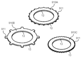
- the metal processed product 1 may also be, for example, a flat washer 910A, 910B, 910C having teeth 911 as shown in FIG. 17.
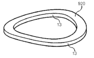
- the metal processed product 1 may be, for example, a wavy circular disc spring 920 as shown in FIG. 18.
- the disc spring 920 in FIG. 18 may be manufactured by processing, for example, the flat washer 900 shown in FIG. 16 into a wavy shape.
- the metal processed product 1 may also be, for example, a disc spring 930 having teeth 931 as shown in FIG. 19.
- the metal workpiece 1 is an annular plate member such as those shown in Figures 16 to 19, the outer and inner periphery become the cut ends 13.
- FIG. 20 is a schematic diagram showing an example of a cutting die for processing the flat washer 900.
- FIG. 21 is a schematic diagram showing the state after the blank 9 has been punched using the cutting die of FIG. 20.
- the 20 is a die for manufacturing an annular metal workpiece 90 such as a flat washer 900, and has a hollow cylindrical die (hereinafter referred to as the "outer die") 61, a cylindrical die (hereinafter referred to as the “inner die”) 63, and a hollow cylindrical punch 65 that supports a disk-shaped blank 9 (see FIG. 23).
- the outer die 61 and the inner die 63 are arranged opposite the punch 65, and the blank 9 is cut by pressing the outer die 61 and the inner die 63 into the blank 9 supported by the punch 65.
- the inner diameter of the outer die 61 corresponds to the outer diameter of the metal workpiece 90
- the outer diameter of the inner die 63 corresponds to the inner diameter of the metal workpiece 90.
- the cutting edge of the inner peripheral surface of the outer die 61 and the cutting edge of the outer peripheral surface of the inner die 63 have an R shape with a radius of curvature.
- the edges of the inner peripheral surface and the outer peripheral surface of the punch 65 do not have an R shape.
- the portion 9a that is on the outer side of the outer peripheral surface 91 of the metal workpiece 90 is cut by the outer die 61, and the portion 9b that is on the inner side of the inner peripheral surface 92 of the metal workpiece 90 is cut by the inner die 63.
- the coining die shown in FIG. 22 is a die for coining the cut end 9c of the element 9 after cutting using the die shown in FIG. 20, and has a pad 7 and a coining block 8.
- the pad 7 has a bottom 75, and a central protrusion 76 and a side periphery 77 protruding from the bottom 75.
- the outer peripheral surface of the central protrusion 76 and the inner peripheral surface of the side periphery 77 form the vertical wall surface 70, and the upper surface of the bottom 75 forms the above-mentioned bottom wall surface 71.
- a pressing surface 72 is formed between the bottom wall surface 71 and the vertical wall surface 70.
- the coining block 8 can be annular.
- the central protrusion 76 is passed through a hole 9d of the element 9 formed into a ring shape by cutting, and the element 9 is pressed down by the coining block 8, whereby the cut end 9c of the element 9 can be coined.
- These cutting and coining processes can be used to form a metal processed product 90 (flat washer 900) as shown in Figure 16. However, this figure explains the coining process, and does not show the mechanism for ejecting the product from the die after processing.
- the metal workpiece 1 may be, for example, a disk-shaped plate 940 as shown in FIG. 23.
- the inventors produced a number of processed product samples by varying the conditions of the semi-cutting, finish-cutting, and coining processes over a variety of ranges, as shown in the following Tables 1 to 3.
- a flat Zn-6%Al-3%Mg (by mass) alloy-plated steel sheet having a thickness of 3.2 mm was used as the first element 2.
- the plating coverage of the steel sheet was 90 g/ m2 (one side).
- the first blank 2 was subjected to a semi-cutting step by the method shown in FIG. 10.
- the first die 31 was pressed into the first blank 2 held by the first punch 41 and the first plate holder 51, thereby performing semi-cutting.
- the first die 31 was annular with a circular hole having an inner diameter of 85.00 mm.
- the first punch 41 was cylindrical so as to be insertable into the circular hole of the first die 31.
- the outer diameter of the first punch 41 was changed according to the clearance C 31-41 shown in Table 1.
- the cutting edges of the first die 31 and the first punch 41 were R-shaped with the radii of curvature R D1 and R P1 shown in Table 1.
- the pressing amount D of the first die 31 and the distance C D1-P1 between the first die 31 and the first punch 41 at the bottom dead center were as shown in Table 1.
- the plate thickness t2 of the half-cut portion 21 (see FIG. 10) formed on the first body 2 was measured.
- the measurement results are shown in Table 2.
- the height h (see FIG. 11) of the horn portion 21a of the half-cut portion 21 formed on the first body 2 was calculated using the above-mentioned formula. The calculation results are also shown in Table 1.
- the formulas (a1) to (a5) relating to the half-cutting step in the table are as follows: -0.35 ⁇ t1 ⁇ C 31-41 ⁇ -0.0125 ⁇ t1...(a1)
- t1 is the plate thickness (mm) of the portion of the first body 2 to be partially cut
- C 31-41 is the clearance (mm) between the first die 31 and the first punch 41.
- 0.10 ⁇ t1 ⁇ R D1 ⁇ 1.50 (a2)
- R D1 is the radius of curvature (mm) of the cutting edge of the first die 31 .
- R P1 is the radius of curvature (mm) of the cutting edge of the first punch 41 .
- t1 is the plate thickness (mm) of the portion of the first body 2 to be half-cut
- D is the amount of pressing (mm) of the first die 31 into the half-cut portion 21. 0.20 ⁇ C D1-P1 ...(a5)
- C D1-P1 is the distance (mm) between the first die 31 and the first punch 41 at the bottom dead center.
- the first element body 2 after the half-cutting step was subjected to a finish cutting step by the method shown in Fig. 13 to obtain a second element body 3.
- the finish cutting process was performed by pressing the second die 32 into the first element body 2 held by the second punch 42 and the second plate holder 52.
- the second die 32 was an annular body with a circular hole having an inner diameter of 85.00 mm.
- the second punch 42 was cylindrical so as to be insertable into the circular hole of the second die 32.
- the outer diameter of the second punch 42 was changed according to the clearance C 32-42 shown in Table 2.
- the cutting edge of the second die 32 was R-shaped with a radius of curvature R D2 shown in Table 2.
- the cutting edge of the second punch 42 was square with no roundness.
- the second element 3 obtained in the finish cutting step was subjected to a coining step by the method shown in Fig. 14 to obtain a processed product sample.
- the coining process was performed by pressing the corner portion 13m of the cut end portion 13 of the second element 3 against the pressing surface 72 of the pad 7.
- the pressing surface 72 of the pad 7 was flat or curved as shown in Table 2.
- the coining area Ar was changed as shown in Table 2.
- whisker burrs those in which whisker-like burrs fell off due to coining were rated as “present.” Those in which the burrs were crushed by coining were rated as “absent,” and those in which the burrs were not completely crushed by coining and remained floating or those in which the burrs fell off after coining were rated as "present.”
- whisker burrs those in which plating components have fallen off are referred to as whisker burrs
- burrs those in which main component is the steel base of the steel plate are referred to as burrs.
- Examples 1 to 18 of the present invention are examples in which the height h0 of the protrusion 13h on the cut end surface of the processed sample is 0.20 mm or less.
- Comparative Examples 1 to 5 are examples in which the height h0 of the protrusion 13h on the cut end surface of the processed sample exceeds 0.20 mm, or processing was stopped during semi-cutting or finish cutting.
- the clearance C 31-41 (mm) between the first die 31 and the first punch 41 is set to a negative clearance
- the cutting edge of the first die 31 and the cutting edge of the first punch 41 are R-shaped with predetermined radii of curvature R D1 , R P1 (mm).
- Fig. 24 is a graph showing the relationship between the height h of the horn portion 21a after half-cutting (before finish cutting) in the embodiment and the coining area Ar of the pad 7 used in the coining process.
- the vertical axis of the graph shown in Fig. 24 is the height h (mm) of the horn portion 21a after half-cutting.
- the height h of the horn portion 21a after half-cutting is as described with reference to Fig. 11.
- the horizontal axis of the graph shown in Fig. 24 is the coining area Ar (mm 2 ) of the pad 7 used in the coining process.
- the coining area Ar refers to the area of the region surrounded by the extension surface 70a of the vertical wall surface 70, the extension surface 71a of the bottom wall surface 71, and the pressing surface 72 when the pad 7 is viewed in a cross section along the pressing direction of the corner portion 13m as shown in Fig. 14.
- the triangular or circular plots labeled “a1” through “a18” indicate the height h and coining area Ar of the horn portion 21a in invention examples 1 through 18.
- the cross plots labeled “b1” through “b3” indicate the height h and coining area Ar of the horn portion 21a in comparative examples 1 through 3.
- "a” indicates the plot of an invention example
- "b” indicates the plot of a comparative example.
- the plot numbers correspond to the numbers of each example.
- the triangular plots (a3, a6, a10, a11, a13, a18) show the height h and coining area Ar of the horn portion 21a after half-cutting when the height h0 of the protrusion 13h is 0.20 mm or less but burrs have occurred.
- the circular plots (a1, a2, a4, a5, a7-a9, a12, a14-a17) show the height h and coining area Ar of the horn portion 21a after half-cutting when the height h0 of the protrusion 13h is 0.20 mm or less and burrs have not occurred.
- the cross plots representing the comparative examples 1-3 show the height h and coining area Ar of the horn portion 21a after half-cutting when the height h0 of the protrusion 13h exceeds 0.20 mm and burrs have occurred.
- the graph in Figure 24 shows that the height h0 of the protrusion 13h and the occurrence of burrs are correlated with the height h of the horn portion 21a after half-cutting (before finish-cutting) and the coining area Ar of the pad 7 used in the coining process.
- Inventive examples 1 to 14 are examples that satisfy the above-mentioned formulas (a1) to (a5) regarding the semi-cutting process and formulas (b1) and (b2) regarding the finish cutting process.
- invention examples 15 to 17 are examples that do not satisfy at least one of formulas (a1) to (a5) regarding the half-cutting process. More specifically, invention examples 15 and 16 do not satisfy formula (a2), and invention example 17 does not satisfy formulas (a3) and (a4).
- the ratio L1/t1 of the remaining plating component length L1 where the sheared surface 13d is covered by the plating layer 13f on the surface of the plated metal sheet to the sheet thickness t1 of the cut end 13 is set to 0.80 or more.
- the ratio L1/t1 was below 0.80. From these results, it can be seen that it is preferable to satisfy the formulas (a1) to (a5) regarding the semi-cutting process described above.
- Inventive Example 18 is an example that does not satisfy at least one of formulas (b1) and (b2) regarding the finishing cutting process. More specifically, Inventive Example 18 does not satisfy formula (b1).
- the target height Lc in the sheet thickness direction T of the upper end of the plating layer 13k that wraps around from the lower surface 13b of the cut end 13 and is based on the lower surface 13b of the cut end 13 is at least 0.10 times the radius of curvature R0 or the tapered surface height C0 of the coining surface 13e.
- the height Lc is less than 0.10 times the radius of curvature R0 or the tapered surface height C0.
- a method for manufacturing a metal processed product comprising the steps of: using a plated metal sheet having a plating layer on a surface thereof as a material; cutting ends along a thickness direction of the material; and forming a coining surface on a corner portion of the cutting ends, the method comprising the steps of: a half-cutting step of cutting a first body formed from the material in half in a plate thickness direction using a first die and a first punch to form a half-cut portion; a finish cutting step of finish-cutting the half-cut portion in the same direction as the half-cutting using a second die and a second punch to obtain a second body having the cut end portion; a coining process in which a corner portion of the cut end portion of the second element is pressed against a pad to obtain a metal processed product having a coining surface formed on the corner portion; Equipped with Regarding the semi-cutting step, The clearance C 31-41 (mm) between the first
- the coining area Ar (mm 2 ) is set so as to further satisfy the following formula: h ⁇ 1.20Ar 2 -2.07Ar+0.90 A method for manufacturing a metal processed product as described in claim 1.
- the clearance C 31-41 (mm) between the first die and the first punch satisfies the following formula (a1): -0.35 ⁇ t1 ⁇ C 31-41 ⁇ -0.0125 ⁇ t1...(a1)
- t1 is the plate thickness (mm) of the half-cutting target portion of the first body
- the radius of curvature R D1 (mm) of the cutting edge of the first die satisfies the following formula (a2): 0.10 ⁇ t1 ⁇ R D1 ⁇ 1.50 (a2)
- the radius of curvature R P1 (mm) of the cutting edge of the first punch satisfies the following formula (a3): 0.10 ⁇ t1 ⁇ R P1 ⁇ 3.00 (a3)
- the clearance C 32-42 (mm) between the second die and the second punch satisfies the following formula (b1): 0.01 ⁇ C 32-42 ⁇ 0.20 ⁇ t2...(b1)
- t2 is a plate thickness (mm) of the half-cut portion of the first blank, which corresponds to a distance along a pressing direction of the first die between a connection position of the cutting edge of the first die and a side surface and an upper surface of the cutting edge of the first punch that contacts the lower surface of the first blank when the first die is pressed down to the bottom dead center
- the cutting edge of the second die is formed into an R shape having a predetermined radius of curvature R D2 (mm)
- the radius of curvature R D2 (mm) of the cutting edge of the second die satisfies the following formula (b2): 0.25 ⁇ R D2 ⁇ 1.50 ⁇ t2 ...
- the shear surface has a first shear surface continuing to the sag in the plate thickness direction, and a second shear surface continuing to the first shear surface, and the inclination angle ⁇ d1 of the first shear surface with respect to the plate thickness direction and the inclination angle ⁇ d2 of the second shear surface with respect to the plate thickness direction satisfy ⁇ d1> ⁇ d2, a ratio L1/t1 of a remaining length L1 (mm) of the plating component at which the sheared surface is covered with the plating layer on the surface to a
Landscapes
- Engineering & Computer Science (AREA)
- Mechanical Engineering (AREA)
- Shaping Metal By Deep-Drawing, Or The Like (AREA)
Priority Applications (4)
| Application Number | Priority Date | Filing Date | Title |
|---|---|---|---|
| CN202480018438.4A CN120897807A (zh) | 2023-06-27 | 2024-06-18 | 金属制加工品的制造方法以及金属制加工品 |
| KR1020257031218A KR20250153239A (ko) | 2023-06-27 | 2024-06-18 | 금속제 가공품의 제조 방법 및 금속제 가공품 |
| JP2025529667A JPWO2025004910A1 (https=) | 2023-06-27 | 2024-06-18 | |
| MX2025014468A MX2025014468A (es) | 2023-06-27 | 2025-12-02 | Metodo para fabricar articulo metalico procesado y articulo metalico procesado |
Applications Claiming Priority (2)
| Application Number | Priority Date | Filing Date | Title |
|---|---|---|---|
| JP2023105174 | 2023-06-27 | ||
| JP2023-105174 | 2023-06-27 |
Publications (1)
| Publication Number | Publication Date |
|---|---|
| WO2025004910A1 true WO2025004910A1 (ja) | 2025-01-02 |
Family
ID=93939016
Family Applications (1)
| Application Number | Title | Priority Date | Filing Date |
|---|---|---|---|
| PCT/JP2024/022099 Ceased WO2025004910A1 (ja) | 2023-06-27 | 2024-06-18 | 金属製加工品の製造方法及び金属製加工品 |
Country Status (6)
| Country | Link |
|---|---|
| JP (1) | JPWO2025004910A1 (https=) |
| KR (1) | KR20250153239A (https=) |
| CN (1) | CN120897807A (https=) |
| MX (1) | MX2025014468A (https=) |
| TW (1) | TWI903586B (https=) |
| WO (1) | WO2025004910A1 (https=) |
Citations (2)
| Publication number | Priority date | Publication date | Assignee | Title |
|---|---|---|---|---|
| JPH0657325A (ja) * | 1992-08-12 | 1994-03-01 | Kobe Steel Ltd | せん断加工部分を有する高強度板材の疲労強度改善方法 |
| WO2022039168A1 (ja) * | 2020-08-17 | 2022-02-24 | 日本製鉄株式会社 | 加工品及び加工品製造方法 |
Family Cites Families (3)
| Publication number | Priority date | Publication date | Assignee | Title |
|---|---|---|---|---|
| CN110177633B (zh) * | 2016-12-26 | 2020-11-20 | 日铁日新制钢株式会社 | 具有切断端面的表面处理钢板的部件及其制造方法 |
| TWI695746B (zh) * | 2016-12-28 | 2020-06-11 | 日商日新製鋼股份有限公司 | 具有切斷端面之表面處理鋼板的零件及其切斷加工方法 |
| MX2023001895A (es) * | 2020-08-17 | 2023-03-10 | Nippon Steel Corp | Producto procesado y metodo de produccion de producto procesado. |
-
2024
- 2024-06-18 JP JP2025529667A patent/JPWO2025004910A1/ja active Pending
- 2024-06-18 CN CN202480018438.4A patent/CN120897807A/zh active Pending
- 2024-06-18 WO PCT/JP2024/022099 patent/WO2025004910A1/ja not_active Ceased
- 2024-06-18 KR KR1020257031218A patent/KR20250153239A/ko active Pending
- 2024-06-24 TW TW113123373A patent/TWI903586B/zh active
-
2025
- 2025-12-02 MX MX2025014468A patent/MX2025014468A/es unknown
Patent Citations (2)
| Publication number | Priority date | Publication date | Assignee | Title |
|---|---|---|---|---|
| JPH0657325A (ja) * | 1992-08-12 | 1994-03-01 | Kobe Steel Ltd | せん断加工部分を有する高強度板材の疲労強度改善方法 |
| WO2022039168A1 (ja) * | 2020-08-17 | 2022-02-24 | 日本製鉄株式会社 | 加工品及び加工品製造方法 |
Also Published As
| Publication number | Publication date |
|---|---|
| TW202500285A (zh) | 2025-01-01 |
| MX2025014468A (es) | 2026-01-07 |
| TWI903586B (zh) | 2025-11-01 |
| KR20250153239A (ko) | 2025-10-24 |
| CN120897807A (zh) | 2025-11-04 |
| JPWO2025004910A1 (https=) | 2025-01-02 |
Similar Documents
| Publication | Publication Date | Title |
|---|---|---|
| JP7140298B2 (ja) | 加工品及び加工品製造方法 | |
| US20250235938A1 (en) | Cutting method and cut article | |
| JP7358608B2 (ja) | 加工品製造方法 | |
| JP7338573B2 (ja) | せん断刃、せん断金型、金属板のせん断加工方法、及びプレス部品の製造方法 | |
| WO2025004910A1 (ja) | 金属製加工品の製造方法及び金属製加工品 | |
| JP7709048B2 (ja) | 加工品及び加工品製造方法 | |
| TWI909514B (zh) | 金屬製加工品的製造方法 | |
| CN114080280A (zh) | 坯料的制造方法及装置、冲压成型品的制造方法、形状判定方法及程序、以及坯料 | |
| JP7155784B2 (ja) | 表面処理鋼板の切断方法 | |
| HK40128290A (zh) | 金属制加工品的制造方法以及金属制加工品 | |
| EP4458488A1 (en) | Processing device, method for manufacturing metal member, and metal member | |
| EP4474086A1 (en) | Steel material, automobile component, shearing device, and manufacturing method for steel material | |
| JP4510572B2 (ja) | 疲労特性に優れた打ち抜き端面を有する自動車用部品の製造方法 | |
| JP7135767B2 (ja) | 表面処理鋼板の切断方法 | |
| HK40082945A (en) | Processed product and method for producing processed product | |
| EP4414111A1 (en) | Cutting device and multi-layer material | |
| HK40083549A (en) | Processed article and method for manufacturing processed article | |
| JP7436841B2 (ja) | 板材の曲げ端割れの評価方法 | |
| JPH10118725A (ja) | 疲労特性に優れた厚手鋼板の打抜方法 | |
| WO2025134922A1 (ja) | 金属製部品の製造方法及び金属製部品 | |
| KR20260003208A (ko) | 가공 장치, 금속제 부재의 제조 방법, 및 금속제 부재 | |
| CN115770811A (zh) | 一种汽车零部件冲压方法 | |
| JP3180755B2 (ja) | クランク軸鍛造品のバリ抜き加工装置と方法 | |
| JPH10118724A (ja) | 疲労耐久性に優れた厚手鋼板の打抜方法 | |
| JP2000094086A (ja) | クランク軸鍛造品のバリ抜き方法 |
Legal Events
| Date | Code | Title | Description |
|---|---|---|---|
| 121 | Ep: the epo has been informed by wipo that ep was designated in this application |
Ref document number: 24831772 Country of ref document: EP Kind code of ref document: A1 |
|
| ENP | Entry into the national phase |
Ref document number: 2025529667 Country of ref document: JP Kind code of ref document: A |
|
| WWE | Wipo information: entry into national phase |
Ref document number: 2025529667 Country of ref document: JP |
|
| WWE | Wipo information: entry into national phase |
Ref document number: 202480018438.4 Country of ref document: CN |
|
| ENP | Entry into the national phase |
Ref document number: 1020257031218 Country of ref document: KR Free format text: ST27 STATUS EVENT CODE: A-0-1-A10-A15-NAP-PA0105 (AS PROVIDED BY THE NATIONAL OFFICE) |
|
| WWP | Wipo information: published in national office |
Ref document number: 1020257031218 Country of ref document: KR |
|
| WWP | Wipo information: published in national office |
Ref document number: 202480018438.4 Country of ref document: CN |
|
| WWE | Wipo information: entry into national phase |
Ref document number: 202517107133 Country of ref document: IN |
|
| WWE | Wipo information: entry into national phase |
Ref document number: MX/A/2025/014468 Country of ref document: MX |
|
| WWE | Wipo information: entry into national phase |
Ref document number: 2501008537 Country of ref document: TH |
|
| WWP | Wipo information: published in national office |
Ref document number: 202517107133 Country of ref document: IN |
|
| WWP | Wipo information: published in national office |
Ref document number: MX/A/2025/014468 Country of ref document: MX |
|
| NENP | Non-entry into the national phase |
Ref country code: DE |