WO2025004889A1 - ガスバリア積層体、並びにこれを用いた包装材及び真空断熱材 - Google Patents
ガスバリア積層体、並びにこれを用いた包装材及び真空断熱材 Download PDFInfo
- Publication number
- WO2025004889A1 WO2025004889A1 PCT/JP2024/021889 JP2024021889W WO2025004889A1 WO 2025004889 A1 WO2025004889 A1 WO 2025004889A1 JP 2024021889 W JP2024021889 W JP 2024021889W WO 2025004889 A1 WO2025004889 A1 WO 2025004889A1
- Authority
- WO
- WIPO (PCT)
- Prior art keywords
- gas barrier
- polyvinyl alcohol
- based resin
- layer
- resin layer
- Prior art date
- Legal status (The legal status is an assumption and is not a legal conclusion. Google has not performed a legal analysis and makes no representation as to the accuracy of the status listed.)
- Ceased
Links
Images

Classifications
-
- B—PERFORMING OPERATIONS; TRANSPORTING
- B32—LAYERED PRODUCTS
- B32B—LAYERED PRODUCTS, i.e. PRODUCTS BUILT-UP OF STRATA OF FLAT OR NON-FLAT, e.g. CELLULAR OR HONEYCOMB, FORM
- B32B27/00—Layered products comprising a layer of synthetic resin
- B32B27/30—Layered products comprising a layer of synthetic resin comprising vinyl (co)polymers; comprising acrylic (co)polymers
-
- B—PERFORMING OPERATIONS; TRANSPORTING
- B32—LAYERED PRODUCTS
- B32B—LAYERED PRODUCTS, i.e. PRODUCTS BUILT-UP OF STRATA OF FLAT OR NON-FLAT, e.g. CELLULAR OR HONEYCOMB, FORM
- B32B7/00—Layered products characterised by the relation between layers; Layered products characterised by the relative orientation of features between layers, or by the relative values of a measurable parameter between layers, i.e. products comprising layers having different physical, chemical or physicochemical properties; Layered products characterised by the interconnection of layers
- B32B7/02—Physical, chemical or physicochemical properties
- B32B7/022—Mechanical properties
-
- Y—GENERAL TAGGING OF NEW TECHNOLOGICAL DEVELOPMENTS; GENERAL TAGGING OF CROSS-SECTIONAL TECHNOLOGIES SPANNING OVER SEVERAL SECTIONS OF THE IPC; TECHNICAL SUBJECTS COVERED BY FORMER USPC CROSS-REFERENCE ART COLLECTIONS [XRACs] AND DIGESTS
- Y02—TECHNOLOGIES OR APPLICATIONS FOR MITIGATION OR ADAPTATION AGAINST CLIMATE CHANGE
- Y02W—CLIMATE CHANGE MITIGATION TECHNOLOGIES RELATED TO WASTEWATER TREATMENT OR WASTE MANAGEMENT
- Y02W30/00—Technologies for solid waste management
- Y02W30/50—Reuse, recycling or recovery technologies
- Y02W30/80—Packaging reuse or recycling, e.g. of multilayer packaging
Definitions
- Patent Document 1 discloses a gas barrier laminate characterized by having, in this order, a substrate having a polyethylene naphthalate layer, a layer made of a composition containing an acrylic polyol and an isocyanate compound, and an inorganic thin film layer.
- the inventors selected polyolefin resin as a material with excellent recyclability. However, the inventors' investigations revealed that there was room for improvement in barrier properties after bending when attempting to realize a mono-material using polyolefin resin.
- the present disclosure provides a gas barrier laminate that includes a polyolefin-based substrate layer and has excellent gas barrier properties even after folding.
- the present disclosure provides a packaging material and a vacuum insulation material that use this gas barrier laminate.
- the present disclosure provides the following gas barrier laminate, packaging material, and vacuum insulation material.
- a polyolefin-based substrate layer A first polyvinyl alcohol-based resin layer; A deposition layer; A second polyvinyl alcohol-based resin layer; in this order, the vapor deposition layer is in direct contact with the first polyvinyl alcohol-based resin layer and the second polyvinyl alcohol-based resin layer,
- a gas barrier laminate wherein the second polyvinyl alcohol-based resin layer has a nanoindenter indentation hardness of 0.5 GPa or less in a cross section.
- a gas barrier laminate that includes a polyolefin-based substrate layer and has excellent gas barrier properties even after folding.
- a packaging material and a vacuum insulation material using this gas barrier laminate are provided.
- the gas barrier laminate according to this embodiment has a laminate structure including, in this order, a polyolefin-based substrate layer, a first polyvinyl alcohol-based resin layer, a vapor deposition layer, and a second polyvinyl alcohol-based resin layer, the vapor deposition layer is in direct contact with the first polyvinyl alcohol-based resin layer and the second polyvinyl alcohol-based resin layer, and the indentation hardness of the cross section of the second polyvinyl alcohol-based resin layer measured with a nanoindenter is 0.5 GPa or less.
- the gas barrier laminate has excellent gas barrier properties even after bending.
- the inventors speculate that the reason for this effect is as follows. That is, the deposition layer is hard and brittle, and is easily damaged by bending.
- the deposition layer is in direct contact with the first and second polyvinyl alcohol-based resin layers.
- the indentation hardness of the cross section of the second polyvinyl alcohol-based resin layer measured with a nanoindenter is 0.5 GPa or less.
- the polyvinyl alcohol-based resin layer acts as a flexible layer to prevent cracks in the deposition layer from expanding, and as a gas barrier layer to fill in defects in the deposition layer. Therefore, the gas barrier laminate has excellent gas barrier properties even after bending.
- gas may escape from the other layer through defects in the deposition layer.
- the film constituting the base layer may be subjected to various pretreatments such as corona treatment, plasma treatment, and flame treatment on the lamination surface as long as the barrier performance is not impaired, or a coating layer such as an easy-adhesion layer may be provided.
- the PVA may be a copolymerized or post-modified modified PVA.
- the copolymerized modified PVA can be obtained, for example, by copolymerizing a vinyl ester with an unsaturated monomer copolymerizable with the vinyl ester, followed by saponification.
- the post-modified PVA can be obtained by copolymerizing an unsaturated monomer in the presence of a polymerization catalyst with the PVA obtained by polymerizing a vinyl ester and then saponifying it.
- the amount of modification in the modified PVA can be less than 50 mol% from the viewpoint of exhibiting sufficient gas barrier properties, and can be 10 mol% or more from the viewpoint of obtaining the effect of modification.
- the thickness of the deposition layer can be 5 to 80 nm. If the thickness is 5 nm or more, it is easier to obtain sufficient gas barrier properties. Furthermore, if the thickness is 80 nm or less, the occurrence of cracks due to deformation caused by internal stress in the thin film is suppressed, and deterioration of gas barrier properties is easily suppressed. From the above viewpoint, the thickness of the deposition layer may be 10 to 50 nm, or 20 to 40 nm.
- the ratio (S2/S1) of the nanoindenter indentation hardness (S2) of the cross section of the second polyvinyl alcohol-based resin layer to the nanoindenter indentation hardness (S1) of the cross section of the first polyvinyl alcohol-based resin layer is preferably 3 to 10, since this provides even better gas barrier properties after bending.
- the second polyvinyl alcohol resin layer may contain Si.
- the second polyvinyl alcohol resin layer may be a cured product of a raw material containing a polyvinyl alcohol resin and a silane compound.
- the silane compound include tetraalkoxysilanes such as tetramethoxysilane and tetraethoxysilane, and silazanes such as hexamethyldisilazane.
- Examples of the silane compound include compounds generally used as silane coupling agents and polysiloxane compounds having siloxane bonds.
- silane coupling agent examples include epoxysilanes (glycidoxypropyltrimethoxysilane, etc.), (meth)acrylic silanes (acryloxypropyltrimethoxysilane, etc.), aminosilanes, ureidosilanes, isocyanate silanes, isocyanurate silanes (tris(3-trialkoxysilylpropyl)isocyanurate, etc.), and mercaptosilanes.
- the amount of the silane compound in the raw material can be 0.1 to 10 parts by mass, or may be 0.5 to 8 parts by mass, or may be 1 to 5 parts by mass, per part by mass of the polyvinyl alcohol-based resin, since this adjusts the indentation hardness by a nanoindenter on the cross section of the second polyvinyl alcohol-based resin layer and the resulting gas barrier laminate has excellent gas barrier properties after bending.
- a coating liquid containing a polyvinyl alcohol-based resin and a liquid medium can be used.
- the coating liquid can be obtained, for example, by dissolving a powder of a polyvinyl alcohol-based resin obtained by synthesis in a liquid medium.
- the liquid medium include water, dimethyl sulfoxide, dimethylformamide, dimethylacetamide, N-methylpyrrolidone, various glycols, polyhydric alcohols such as trimethylolpropane, and amines such as ethylenediamine and diethylenetriamine. These may be used alone or in combination of two or more. From the viewpoint of reducing environmental load, water can be used as the liquid medium.
- the coating liquid can be obtained by dissolving a powder of a polyvinyl alcohol-based resin in water at a high temperature (for example, 80°C).
- the coating liquid may contain additives such as isocyanate and polyethyleneimine to improve adhesion.
- the coating liquid may also contain additives such as preservatives, plasticizers, alcohol, and surfactants.
- the coating liquid can be applied to the substrate layer by any appropriate method.
- the coating liquid can be applied by a wet film-forming method using, for example, a gravure coater, a dip coater, a reverse coater, a wire bar coater, a die coater, or the like.
- the application temperature and drying temperature of the coating liquid are not particularly limited and can be, for example, 50°C or higher.
- the above adhesive component may be applied to the substrate layer and then dried to form an adhesive layer on the substrate layer.
- the thickness of the adhesive layer can be 0.1 to 50 ⁇ m, and may be 0.5 to 20 ⁇ m, from the standpoint of adhesion, followability, processability, etc.
- the base layer and the first polyvinyl alcohol-based resin layer may be coextruded layers formed by a coextrusion method. When these layers are coextruded layers, the laminate tends to be tightly adhered and to easily maintain gas barrier properties.
- the coating liquid for forming the second polyvinyl alcohol-based resin layer may contain a silane compound.
- the content of the silane compound in the coating liquid may be adjusted so that a desired amount of the silane compound is contained relative to the amount of polyvinyl alcohol-based resin.
- a small amount of a second or third component such as ethylene or butene may be used as a raw material monomer during polypropylene synthesis.
- a second or third component such as ethylene or butene
- polyethylene is preferable from the viewpoint that the polyolefin resin is highly flexible, so that it is difficult to break even when a heavy liquid is contained, and even when used as a packaging material to be subjected to vacuum treatment, it is easy to follow regardless of the contents and tends to be less likely to deteriorate in gas barrier properties.
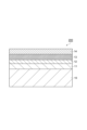
- the packaging material 200 shown in FIG. 2 comprises a gas barrier laminate 100 and a sealant layer 14 provided on the surface of the gas barrier laminate 100 opposite to the substrate layer (on the surface of the second polyvinyl alcohol-based resin layer).
- the content of the polyolefin-based resin can be 90% by mass or more (preferably 95% by mass or more) based on the total mass of the packaging material 200.
- Such a packaging material 200 can realize a mono-material.
- the packaging material 200 is preferably used for a package that is subjected to a vacuum treatment. In the vacuum treatment, the packaging material is bent due to the contents.
- the packaging material 200 comprises a gas barrier laminate that has excellent gas barrier properties even after folding, it has excellent gas barrier properties even after vacuum treatment.
- the packaging material 200 is preferably used for a package that is subjected to a freezing treatment.
- the package comprises a packaging bag composed of the packaging material 200 and contents contained in the packaging bag.
- Contents include, for example, food, liquids, medicines, electronic components, and insulating core materials described below.
- the polyolefin resin content of the packaging material 200 is preferably 90% by mass based on the total amount of the packaging material 200.
- the packaging material 200 may further include a resin layer between the sealant layer and the gas barrier laminate.
- a resin layer examples include nylon, polyethylene terephthalate, and polyolefin.
- the pressure inside the packaging material 300 may be 10 5 Pa or less, 10 2 Pa or less, 10 -1 Pa or less, 10 -5 Pa or less, or 10 -8 Pa or less, or 10 -8 Pa or more, 10 -5 Pa or more, 10 -1 Pa or more, or 10 2 Pa or more.
- Vacuum insulation materials can be used, for example, as a component that covers the outer surface of cold-keeping equipment and heat-keeping equipment to maintain insulation, a component that covers the outer surface of cold-keeping containers and heat-keeping containers to maintain insulation, and as an exterior wall material used in construction applications.
- cold-keeping equipment and heat-keeping equipment include vending machines, refrigerators, freezers, thermoses, and rice cookers.
- cold-keeping equipment and heat-keeping equipment include cooler boxes and water bottles.
- buildings in which exterior wall materials are used include homes and cold storage warehouses.
- the gas barrier laminate 100b is arranged so that the second polyvinyl alcohol-based resin layer 13 is on the resin layer side 15, but the base layer 10 may also be positioned on the resin layer 15 side.
- Example 1 An OPP film (polyolefin-based base layer) was formed using a polypropylene monomer resin, and an EVOH layer (first polyvinyl alcohol-based resin layer) was formed on the surface of the OPP film by co-extrusion. The mass per unit area of the EVOH layer was 0.97 g/ m2 .
- silicon oxide was deposited on the surface of the first polyvinyl alcohol-based resin layer to form a SiOx deposited film (deposited layer, thickness: 50 nm).
- a mixture was obtained by mixing coating liquids A, B, and C.
- the mixing ratio of coating liquids A, B, and C was adjusted so that the solid content mass ratio of PVA/SiO 2 /silane coupling agent (SC agent) was as shown in Table 1.
- SC agent solid content mass ratio of PVA/SiO 2 /silane coupling agent
- Example 2 A gas barrier laminate was obtained in the same manner as in Example 1, except that, instead of using a SiOx vapor deposition film, an electron beam heating type vacuum deposition apparatus was used to vapor deposit AL on the surface of the first polyvinyl alcohol-based resin layer to form an AL vapor deposition film (thickness: 50 nm).
- Example 3 A polypropylene film (manufactured by Mitsui Chemicals Tohcello, product name "ME-1", thickness: 20 ⁇ m) was prepared as a base layer.
- An EVOH solution (manufactured by Mitsubishi Chemical, product name: 16DX) was dissolved in a mixed solution of water and IPA to prepare a solution with a solid content of 5 mass%.
- the obtained solution was applied to the corona-treated surface of the polypropylene film to form a coating film, and the coating film was dried to form a first polyvinyl alcohol-based resin layer (thickness: 0.8 ⁇ m).
- a deposition layer was formed on the surface of the first polyvinyl alcohol-based resin layer, and a second polyvinyl alcohol-based resin layer on the deposition layer was formed to obtain a gas barrier laminate.
- Example 4 A gas barrier laminate was obtained in the same manner as in Example 3, except that the mixing ratio of the coating solutions A, B and C (PVA/SiO 2 /SC agent) was adjusted to the solid content mass ratio shown in Table 1.
- Example 5 A gas barrier laminate was obtained in the same manner as in Example 1, except that a biaxially oriented HDPE (BOPE: Biaxially Oriented Polyethylene) film was used as the polyolefin-based base layer instead of the OPP film.
- BOPE Biaxially Oriented Polyethylene
- Example 6 A gas barrier laminate was obtained in the same manner as in Example 2, except that a biaxially oriented HDPE film (thickness: 24.2 nm) was used as the polyolefin-based base layer instead of the OPP film, and the thickness of the Al vapor-deposited film was set to 75 nm.
- a biaxially oriented HDPE film thickness: 24.2 nm
- Example 7 A gas barrier laminate was obtained in the same manner as in Example 5, except that the mixing ratio of the coating solutions A, B and C (PVA/SiO 2 /SC agent) was adjusted to the solid content mass ratio shown in Table 2.
- Example 1 A gas barrier laminate was obtained in the same manner as in Example 1, except that the mixing ratio of the coating solutions A, B and C was set to the solid content mass ratio shown in Table 1.
- Example 3 A gas barrier laminate was obtained in the same manner as in Example 1, except that the second polyvinyl alcohol-based resin layer was not formed.
- Example 4 A polypropylene film (thickness: 20 ⁇ m) was prepared as the substrate layer. An anchor coat layer was formed on the surface of the substrate layer. Silicon oxide was evaporated on the surface of the anchor coat layer using an electron beam heating vacuum evaporation device to form a SiO x evaporated film (evaporated layer, thickness: 50 nm). A mixture was obtained by mixing coating liquids A, B, and C in the same manner as in Example 1. The mixture was applied to the surface of the evaporated layer opposite the substrate layer to form a coating film, and the coating film was dried to form a second polyvinyl alcohol-based resin layer (thickness: 300 nm). This resulted in a gas barrier laminate.
- Example 5 A gas barrier laminate was obtained in the same manner as in Example 5, except that the mixing ratio of the coating solutions A, B and C (PVA/SiO 2 /SC agent) was adjusted to the solid content mass ratio shown in Table 2.
- Example 6 A gas barrier laminate was obtained in the same manner as in Example 5, except that the second polyvinyl alcohol-based resin layer was not formed.
- the indentation hardness of the first and second polyvinyl alcohol-based resin layers of the gas barrier laminates obtained in each of the Examples and Comparative Examples was measured by a nanoindentation method.
- the nanoindentation method is a measurement method in which a quasi-static indentation test is performed on a target measurement object to obtain the mechanical properties of the sample.
- the measurement sample (cross-section sample) was prepared as follows. That is, after corona treatment was performed on both sides of the gas barrier laminate, it was embedded in visible light curable resin D-800. Then, using an ultramicrotome Leica EM UC7 and a diamond knife Microstar LH, the gas barrier laminate was cut perpendicular to the lamination direction. The resulting cross section was finished with a cutting thickness of Feed 100 nm and a cutting speed of Speed 1 mm/s to prepare the measurement sample.
- the measurement was performed using a Hysitron TI-Premier (product name) manufactured by Bruker Japan Co., Ltd. as the measuring device and a Berkovich-type diamond indenter manufactured by Bruker Japan Co., Ltd. as the indenter.
- the measurement conditions were as follows.
- Temperature normal temperature (25°C).
- Mode Load control mode. Pressing and unloading: Pressing was performed up to a load of 15 ⁇ N at a pressing speed of 1.5 ⁇ N/sec, the maximum load was maintained for 5 seconds, and then the load was unloaded at a speed of 1.5 ⁇ N/sec.
- Measurement location A shape image of the cross section of the second polyvinyl alcohol-based resin layer is obtained by a shape measurement function of a measuring device that scans the sample surface with an indenter, and the cross section of the second polyvinyl alcohol-based resin layer is determined from the shape image. Specify 20 points at intervals of 1 ⁇ m or more.
- fused quartz was used as a standard sample to calibrate the relationship between the contact depth and contact projected area between the indenter and the sample.
- the unloading curve in the 60-95% range of the maximum load at the time of unloading was then analyzed using the Oliver-Pharr method to calculate the indentation hardness.
- a first original roll was prepared by winding up the gas barrier laminate (width: 500 mm) of each Example and Comparative Example.
- the gas barrier laminate was fed from the original roll in a roll-to-roll manner and wound up as a second original roll.
- the feeding speed was 50 m/min. If wrinkles were generated on the second original roll, it was rated as "B”, and if no wrinkles were generated, it was rated as "A”.
- Tables 1 and 2 The results are shown in Tables 1 and 2.
- Examples 1 to 4 Comparative Examples 1 to 4
- the gas barrier laminates of each Example and Comparative Example and a CPP film (sealant layer, manufactured by Mitsui Chemicals Tohcello Inc., product name "TUX-MCS", thickness: 60 ⁇ ) were dry laminated with a 3 ⁇ thick two-liquid curing adhesive (manufactured by Mitsui Chemicals, product names "A525" and "A50") to obtain a laminate film.
- the gas barrier laminates were attached so that the surface opposite the base layer faced the CPP film.
- the mass ratio of polyolefin resin (polypropylene) in the laminate film was calculated from the masses of the gas barrier laminate, CPP film (thickness: 60 ⁇ ), and adhesive (thickness: 3 ⁇ ). The results are shown in Table 1.
- Example 5 to 8 Comparative Examples 5 to 7
- the mass ratio of polyolefin resin (polyethylene) in the laminate film was determined in the same manner as in Examples 1 to 4 and Comparative Examples 1 to 4. The results are shown in Table 2.
- Example 1 to 4 ⁇ Oxygen permeability measurement (initial stage)> (Examples 1 to 4, Comparative Examples 1 to 4)
- the gas barrier laminate of each Example and Comparative Example was dry laminated with an adhesive to a CPP film (sealant layer) to obtain a laminate film.
- the gas barrier laminate was laminated so that the surface opposite to the base layer of the gas barrier laminate was faced to the CPP film.
- the oxygen permeability of the laminate film was measured.
- the measurement was performed using an oxygen permeability measuring device (OXTRAN 2/20, manufactured by Modern Control) at a temperature of 30°C and a relative humidity of 70%.
- the measurement method was in accordance with JIS K-7126, Method B (isobaric method), and ASTM D3985-81. The results are shown in Table 1.
- the measured values were expressed in units of [cc/ m2 ⁇ day ⁇ atm].
- Example 5 to 8 Comparative Examples 5 to 7 Except for using the LLDPE film 1 instead of the CPP film as the sealant layer, the oxygen permeability was measured in the same manner as in Examples 1 to 4 and Comparative Examples 1 to 4. The results are shown in Table 2.
- Laminate films were obtained using the gas barrier laminates of each Example and Comparative Example in the same manner as in the oxygen permeability measurement (initial stage).
- the water vapor permeability of the laminate film was measured.
- the measurement was performed using an oxygen permeability measurement device (PERMATRAN 3/31, manufactured by Modern Control) under conditions of a temperature of 40°C and a relative humidity of 90%.
- the measurement method was in accordance with JIS K-7126, Method B (isobaric method), and ASTM D3985-81. The results are shown in Tables 1 and 2. The measured values were expressed in units of [g/ m2 ⁇ day].
- a laminate film was obtained using the gas barrier laminate of each Example and Comparative Example in the same manner as in the oxygen permeability measurement (initial stage).
- a test piece measuring 210 mm x 297 mm was cut out from the laminate film. Both ends of the test piece were attached together and rolled into a cylindrical shape. Both ends of the cylindrical test piece were held by a fixed head and a driving head. The following steps 1 to 4 were counted as one cycle, and 100 cycles were performed at 25°C. The cycle speed was 40 cycles/min.
- the oxygen permeability after the bending test was measured in the same manner as in the oxygen permeability measurement (initial stage).
- the water vapor permeability after the bending test was measured in the same manner as in the water vapor permeability measurement (initial stage).
- Step 1 The distance between the stationary and driven heads is narrowed from 7 inches to 3.5 inches while twisting the test specimen 440 degrees.
- Step 2 While keeping the test specimen twisted, narrow the head spacing to 1 inch.
- Step 3 Increase head spacing to 3.5 inches.
- Step 4 While untwisting, increase the head spacing to 7 inches.
- Example 1A A gas barrier laminate was obtained in the same manner as in Example 1 of the first study.
- the gas barrier laminate and a CPP film (sealant layer) were dry-laminated with an adhesive to obtain a laminate film.
- the gas barrier laminate was attached so that the surface of the second polyvinyl alcohol-based resin layer side of the gas barrier laminate faced the CPP film.
- Example 1B A laminate film was obtained in the same manner as in Example 1A, except that the LLDPE film 1 was used instead of the CPP film.
- Example 1C A gas barrier laminate was obtained in the same manner as in Example 1 of the first study.
- the gas barrier laminate and the ONY film were dry laminated with an adhesive to obtain a laminate.
- the gas barrier laminate was bonded so that the surface of the second polyvinyl alcohol-based resin layer side and the ONY film faced each other.
- the surface of the laminate on the ONY film side and the LLDPE film 1 were dry laminated with an adhesive to obtain a laminate film.
- Comparative Example 3A A laminate film was obtained in the same manner as in Example 1A, except that the gas barrier laminate of Comparative Example 3 was used instead of the gas barrier laminate of Example 1.
- Example 1D Two gas barrier laminates were obtained in the same manner as in Example 1 of the first study.
- the second polyvinyl alcohol-based resin layer of the first gas barrier laminate of Example 1 was dry-laminated with an adhesive to an ONY film to obtain a first laminate.
- the surface of the ONY film side of the first laminate and the surface of the second polyvinyl alcohol-based resin layer side of the second gas barrier laminate of Example 1 were dry-laminated with an adhesive to obtain a second laminate.
- the surface of one of the base layer sides of the second laminate and an LLDPE film 2 were dry-laminated with an adhesive to obtain a laminate film.
- Comparative Example 3B A laminate film was obtained in the same manner as in Example 1D, except that the gas barrier laminate of Comparative Example 3 was used instead of the gas barrier laminate of Example 1.
- a vacuum insulation material was manufactured from the laminate film of Example 1D and Comparative Example 3B. Specifically, two sheets of each laminate film (size: 300 mm x 300 mm) were prepared. The laminate films were placed opposite each other and three sides were heat-sealed to obtain a packaging bag for containing an insulating core material with only one side open. Glass fiber (290 x 290 mm) that had been dried (temperature: 120 ° C, time: 1 hour) was prepared as an insulating core material. The glass fiber was contained in the packaging bag. The internal space of the packaging bag was degassed to set the pressure inside the bag to 1.0 Pa, and then the opening of the bag was heat-sealed and sealed. As a result, a vacuum insulation material (thickness: 5 mm, length: 300 mm, width: 300 mm) was obtained.
- the vacuum insulation material was stored at 60°C for two weeks.
- the thermal conductivity of the vacuum insulation material was measured before and after storage. Thermal conductivity was measured by the heat flow meter method using a thermal conductivity measuring device (manufactured by Eiko Seiki, product name "HC-074") in accordance with JIS-A-1412-3.
- the thermal conductivity of Example 1D and Comparative Example 3B before storage was both 0.005 [W/M ⁇ K].
- the thermal conductivity of Example 1D after storage remained unchanged at 0.005 [W/M ⁇ K].
- the thermal conductivity of Comparative Example 3B after storage was greater than 0.005 [W/M ⁇ K].
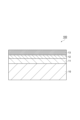
- 10 base material layer, 11...first polyvinyl alcohol-based resin layer, 12...vapor deposition layer, 13...second polyvinyl alcohol-based resin layer, 100...gas barrier laminate, 200, 300...packaging material.
Landscapes
- Engineering & Computer Science (AREA)
- Mechanical Engineering (AREA)
- Laminated Bodies (AREA)
- Thermal Insulation (AREA)
Abstract
Description
[1]ポリオレフィン系基材層と、
第1のポリビニルアルコール系樹脂層と、
蒸着層と、
第2のポリビニルアルコール系樹脂層と、
をこの順序で備える積層構造を有し、
上記蒸着層が、上記第1のポリビニルアルコール系樹脂層及び上記第2のポリビニルアルコール系樹脂層と直接接しており、
上記第2のポリビニルアルコール系樹脂層の断面におけるナノインデンターによる押し込み硬度が、0.5GPa以下である、ガスバリア積層体。
[2]上記第1のポリビニルアルコール系樹脂層の断面におけるナノインデンターによる押し込み硬度(S1)に対する上記第2のポリビニルアルコール系樹脂層の断面におけるナノインデンターによる押し込み硬度(S2)の比率(S2/S1)が、3~10である、[1]に記載のガスバリア積層体。
[3]上記第1のポリビニルアルコール系樹脂層の厚さが、0.5~2.5μmである、[1]又は[2]に記載のガスバリア積層体。
[4]上記第2のポリビニルアルコール系樹脂層が、Siを含む、[1]~[3]のいずれかに記載のガスバリア積層体。
[5]上記第2のポリビニルアルコール系樹脂層が、シランカップリング剤を含む、[1]~[4]のいずれかに記載のガスバリア積層体。
[6]上記蒸着層が、アルミニウム又は酸化ケイ素を含む、[1]~[5]のいずれかに記載のガスバリア積層体。
[7]上記ポリオレフィン系基材層と第1のポリビニルアルコール系樹脂層とが共押出層である、[1]~[6]のいずれかに記載のガスバリア積層体。
[8][1]~[7]のいずれか一項に記載のガスバリア積層体を備える、包装材。
[9]真空処理が施される包装体に用いられる、[8]に記載の包装材。
[10]冷凍処理が施される包装体に用いられる、[8]に記載の包装材。
[11][8]に記載の包装材を備える、真空断熱材。
ポリオレフィン系基材層(以下、単に「基材層」ともいう。)は支持体の一つとなるフィルムであり、ポリオレフィン系樹脂を含む。
ポリビニルアルコール系樹脂としては、ビニルエステル単位がケン化されてなるビニルアルコール単位を有するものであればよく、例えば、ポリビニルアルコール(PVA)、エチレン-ビニルアルコール共重合体(EVOH)が挙げられる。耐熱性やガスバリア性の観点から、EVOHを好適に用いることができる。
蒸着層は、水蒸気、酸素に対するガスバリア性を示す層(ガスバリア層)である。蒸着層は、金属及び無機酸化物の少なくとも一を含んでいてよい。蒸着層は、単層構造でもよいし、積層構造でもよい。蒸着層は、金属蒸着層及び無機酸化物層の少なくとも一を含む。蒸着層が金属蒸着層を備える場合、金属蒸着層に含まれる金属としては、例えばアルミニウム、ステンレスなどが挙げられる。蒸着層が無機酸化物層を備える場合、無機酸化物層に含まれる無機酸化物としては、例えば、酸化アルミニウム、酸化ケイ素、酸化マグネシウム、酸化錫等が挙げられる。透明性及びバリア性の観点から、無機酸化物としては、酸化アルミニウム、酸化ケイ素、及び酸化マグネシウムからなる群より選択されてよい。また、加工時に引っ張り延伸性に優れる観点から、無機酸化物層として酸化ケイ素を用いた層とすることが好ましい。無機酸化物層を用いることにより、ガスバリア積層体のリサイクル性に影響を与えない範囲のごく薄い層で、高いバリア性を得ることができる。
第2のポリビニルアルコール系樹脂層を構成するポリビニルアルコール系樹脂に関しては、第1のポリビニルアルコール系樹脂層の項にて説明した内容を参照することができる。
ガスバリア積層体は、例えば、基材層上に第1のポリビニルアルコール系樹脂層を形成する工程、第1のポリビニルアルコール系樹脂層上に蒸着層を形成する工程、及び、蒸着層上に第2のポリビニルアルコール系樹脂層を形成する工程を備える製造方法により製造することができる。
本工程においては、ポリビニルアルコール系樹脂及び液状媒体を含む塗布液を用いることができる。当該塗布液は、例えば合成により得られたポリビニルアルコール系樹脂の粉末を、液状媒体に溶解させて得ることができる。液状媒体としては、水、ジメチルスルホキシド、ジメチルホルムアミド、ジメチルアセトアミド、N-メチルピロリドン、各種グリコール類、トリメチロールプロパン等の多価アルコール類、エチレンジアミン、ジエチレントリアミン等のアミン類などが挙げられる。これらは単独で、または、二種以上組み合わせて用いてよい。環境負荷低減等の観点から、液状媒体として水を用いることができる。この場合、ポリビニルアルコール系樹脂の粉末を、高温(例えば80℃)の水に溶解させることで塗布液を得ることができる。
蒸着層は、例えば真空成膜で形成することができる。真空成膜では、物理気相成長法あるいは化学気相成長法を用いることができる。物理気相成長法としては、真空蒸着法、スパッタリング法、イオンプレーティング法等を挙げることができるが、これらに限定されるものではない。化学気相成長法としては、熱CVD法、プラズマCVD法、光CVD法等を挙げることができるが、これらに限定されるものではない。
本工程は、第1のポリビニルアルコール系樹脂層を形成する工程と同様に、塗布液を用いることができる。塗布液に関しては、第1のポリビニルアルコール系樹脂層を形成する工程の項にて説明した内容を参照することができる。
包装材は、上記のガスバリア積層体と、ガスバリア積層体の表面上に設けられたシーラント層と、を備える。シーラント層としては、ポリオレフィン系樹脂やポリエステル系樹脂を含む層が挙げられる。ポリオレフィン系樹脂としては、例えばポリエチレン(PE)、ポリプロピレン(PP)、ポリブテン(PB)、シクロオレフィンポリマー等が挙げられる。また、ポリオレフィン系樹脂としては、ポリオレフィンを、不飽和カルボン酸、不飽和カルボン酸の酸無水物、不飽和カルボン酸のエステル等を用いてグラフト変性して得られる酸変性ポリオレフィン等が挙げられる。ポリプロピレン合成時の原料モノマーとして、エチレンやブテン等の第二、第三等の成分を少量用いてもよい。ポリオレフィン系樹脂としては、柔軟性が高いため、液体重量物を収容しても破袋しづらく、真空処理が施される包装材として利用しても内容物に拠らず追従しやすくガスバリア性が一層劣化しにくい傾向があるため、観点から、ポリエチレンであることが好ましい。ポリエチレンは、例えば、低密度ポリエチレン(LDPE)、中密度ポリエチレン(MDPE)、高密度ポリエチレン(HDPE)、線状低密度ポリエチレン(L・LDPE)、エチレン-酢酸ビニル共重合体(EVA)又はエチレン・α-オレフィン共重合体である。図2は、一実施形態に係る包装材を示す模式断面図である。
(フィルム)
・CPPフィルム:東レ社製、商品名「トレファン ZK207」、厚さ60μm
・LLDPEフィルム1:三井化学東セロ社製、商品名「TUX-MCS」、厚さ60μm
・LLDPEフィルム2:三井化学東セロ社製、商品名「FCS」、厚さ40μm
・ONYフィルム:ユニチカ社製、商品名「エンブレムONM」、厚さ15μm
(接着剤)
・三井化学SKCポリウレタン株式会社製、商品名「A525/A52」、2液型
(コーティング液A)
ポリビニルアルコール(商品名:クラレポバール60-98、株式会社クラレ製、以下「PVA」ともいう)を固形分5%の水溶液に調製した。
(コーティング液B)
テトラエトキシシラン(商品名:KBE04、固形分:100%、信越化学工業株式会社製、以下「TEOS」ともいう)とメタノール(関東化学)と0.1N塩酸(関東化学)とを、重量比が17/10/73となるように混合し、固形分5%(重量比SiO2換算)の加水分解溶液を調製した。
(コーティング液C)
1,3,5-トリス(3-メトキシシリルプロピル)イソシアヌレート(シランカップリング剤)を、水/IPA=1/1溶液で、固形分5%(重量比RSi(OH)3換算)の加水分解溶液を調製した。
<ガスバリア積層体の作製>
(実施例1)
ポリプロピレンのモノマー樹脂を使用してOPPフィルム(ポリオレフィン系基材層)を製膜すると同時に、OPPフィルムの表面にEVOH層(第1のポリビニルアルコール系樹脂層)を共押出法により形成した。EVOH層の単位面積当たりの質量は0.97g/m2であった。
SiOx蒸着膜に代えて、電子ビーム加熱方式の真空蒸着装置を用いて、第1のポリビニルアルコール系樹脂層の表面上にALを蒸着させAL蒸着膜(厚さ:50nm)を成膜したこと以外は、実施例1と同様にしてガスバリア積層体を得た。
基材層としてポリプロピレンフィルム(三井化学東セロ社製、商品名「ME-1」、厚さ:20μm)を準備した。EVOH溶液(三菱ケミカル社製、商品名:16DX)を水及びIPA混合溶液に溶解させ固形分が5質量%の溶液を調整した。得られた溶液をポリプロピレンフィルムのコロナ処理がされている面に塗工して塗膜を形成し、塗膜を乾燥させることで第1のポリビニルアルコール系樹脂層(厚さ:0.8μm)を形成した。実施例1と同様にして、第1のポリビニルアルコール系樹脂層の表面上に蒸着層と、蒸着層上の第2のポリビニルアルコール系樹脂層とを形成し、ガスバリア積層体を得た。
コーティング液A、B及びCの混合比率(PVA/SiO2/SC剤)を表1に示す固形分質量比となるように調整したこと以外は、実施例3と同様にしてガスバリア積層体を得た。
ポリオレフィン系基材層としてOPPフィルムに代えて二軸延伸のHDPE(BOPE:Biaxially Oriented Polyethylene)フィルムを用いたこと以外は、実施例1と同様にしてガスバリア積層体を得た。
ポリオレフィン系基材層としてOPPフィルムに代えて二軸延伸のHDPEフィルム(厚さ:24.2nm)を用いたことと、AL蒸着膜の厚さを75nmとしたこと以外は、実施例2と同様にしてガスバリア積層体を得た。
コーティング液A、B及びCの混合比率(PVA/SiO2/SC剤)を表2に示す固形分質量比となるように調整したこと以外は、実施例5と同様にしてガスバリア積層体を得た。
コーティング液A、B及びCの混合比率(PVA/SiO2/SC剤)を表2に示す固形分質量比となるように調整したこと以外は、実施例6と同様にしてガスバリア積層体を得た。
コーティング液A、B及びCの混合比率を表1に示す固形分質量比としたこと以外は、実施例1と同様にしてガスバリア積層体を得た。
ALを蒸着した二軸延伸EVOHフィルム(クラレ社製、商品名「VM-XL」)をガスバリア積層体として用いた。
第2のポリビニルアルコール系樹脂層を形成しなかったこと以外は、実施例1と同様にしてガスバリア積層体を得た。
基材層としてポリプロピレンフィルム(厚さ:20μm)を準備した。基材層の表面上にアンカーコート層を形成した。電子ビーム加熱方式の真空蒸着装置を用いて、アンカーコート層の表面上に酸化ケイ素を蒸着させ、SiOx蒸着膜(蒸着層、厚さ:50nm)を成膜した。実施例1と同様にしてコーティング液A、B及びCを混合した混合物を得た。蒸着層の基材層とは反対側の表面に混合物を塗布して塗膜を形成し塗膜を乾燥することで第2のポリビニルアルコール系樹脂層(厚さ:300nm)を形成した。これによりガスバリア積層体を得た。
コーティング液A、B及びCの混合比率(PVA/SiO2/SC剤)を表2に示す固形分質量比となるように調整したこと以外は、実施例5と同様にしてガスバリア積層体を得た。
第2のポリビニルアルコール系樹脂層を形成しなかったこと以外は、実施例5と同様にしてガスバリア積層体を得た。
AL(厚さ:75nm)を蒸着した二軸延伸のHDPEフィルム(厚さ:25nm)をガスバリア積層体として用いた。
各実施例及び比較例で得られたガスバリア積層体の第1及び第2のポリビニルアルコール系樹脂層の押し込み硬度を測定した。押し込み硬度は、ナノインデンテーション法より測定した。ナノインデンテーション法とは、目的の測定対象に対して準静的な押し込み試験を行い、試料の機械特性を取得する測定法である。
モード:荷重制御モード。
押し込み及び除荷:押し込み速度1.5μN/秒にて荷重15μNまで押し込みを行った後、最大荷重にて5秒間保持後、1.5μN/秒の速度にて除荷した。
測定箇所:圧子によって試料表面を走査する測定装置の形状測定機能によって、第2のポリビニルアルコール系樹脂層の断面の形状像を取得し、形状像から第2のポリビニルアルコール系樹脂層の断面上を1μm以上の間隔で20点指定。
各実施例及び比較例のガスバリア積層体について基材層側の主面と、その反対側の主面との動摩擦係数を測定した。測定はJIS K7125に準拠し、試験幅80×200mm、すべり片の接地面積40cm2、すべり速度100mm/分で実施した。測定値(単位:μD)を以下の基準で評価した。結果を表1及び表2に示した。
A:測定値が1.0μD以下
B:測定値が1.0μD超又は積層体が滑らずジッパリングが発生し測定ができない
各実施例及び比較例のガスバリア積層体(幅:500mm)を巻き取った第1の原反を準備した。ロールツーロールで原反からガスバリア積層体を送り出して第2の原反として巻き取った。送り出しの速度は50m/分とした。第2の原反にシワが生じた場合に「B」の評価とし、シワが生じなかった場合に「A」の評価とした。結果を表1及び表2に示した。
(実施例1~4,比較例1~4)
各実施例及び比較例のガスバリア積層体と、CPPフィルム(シーラント層、三井化学東セロ株式会社製、商品名「TUX-MCS」、厚さ:60μ)を厚さ3μの2液硬化型接着剤(三井化学製、商品名「A525」と「A50」)によりドライラミネートしてラミネートフィルムを得た。ガスバリア積層体の基材層とは反対側の表面とCPPフィルムとが対向するように貼り合わせた。
シーラント層としてCPPフィルムに代えてLLDPEフィルム1を用いたこと以外は、実施例1~4及び比較例1~4と同様にしてラミネートフィルムにおけるポリオレフィン系樹脂(ポリエチレン)の質量比率を求めた。結果を表2に示した。
(実施例1~4,比較例1~4)
各実施例及び比較例のガスバリア積層体とCPPフィルム(シーラント層)とを接着剤によりドライラミネートしてラミネートフィルムを得た。ガスバリア積層体の基材層とは反対側の表面とCPPフィルムとが対向するように貼り合わせた。ラミネートフィルムの酸素透過度を測定した。測定は、酸素透過度測定装置(Modern Control社製、OXTRAN 2/20)を用いて、温度30℃、相対湿度70%の条件で行った。測定方法は、JIS K-7126、B法(等圧法)、及びASTM D3985-81に準拠した。結果を表1に示した。測定値は単位[cc/m2・day・atm]で表記した。
シーラント層としてCPPフィルムに代えてLLDPEフィルム1を用いたこと以外は、実施例1~4及び比較例1~4と同様にして酸素透過度を測定した。結果を表2に示した。
酸素透過度測定(初期)と同様にして各実施例及び比較例のガスバリア積層体を用いてラミネートフィルムを得た。ラミネートフィルムの水蒸気透過度を測定した。測定は酸素透過度測定装置(Modern Control社製、PERMATRAN 3/31)を用いて、温度40℃、相対湿度90%の条件で行った。測定方法は、JIS K-7126、B法(等圧法)、及びASTM D3985-81に準拠した。結果を表1及び表2に示した。測定値は単位[g/m2・day]で表記した。
酸素透過度測定(初期)と同様にして各実施例及び比較例のガスバリア積層体を用いてラミネートフィルムを得た。ラミネートフィルムについて、ラミネート強度を測定した。測定はJIS K6854に準拠し、試験幅15mm、剥離速度300mm/分、剥離角度180°にて行った。結果を表1及び表2に示した。測定値は単位[N/15mm]で表記した。
酸素透過度測定(初期)と同様にして各実施例及び比較例のガスバリア積層体を用いてラミネートフィルムを得た。ラミネートフィルムから210mm×297mmの試験片を切り出した。試験片の両端を貼り合わせて円筒状に丸めた。円筒状にした試験片の両端を固定ヘッドと駆動ヘッドで保持した。以下の工程1~4を1サイクルとして25℃で100サイクル行った。サイクルを行う速さは40サイクル/分とした。屈曲試験後の酸素透過度を酸素透過度測定(初期)と同様にして測定した。屈曲試験後の水蒸気透過度を水蒸気透過度測定(初期)と同様にして測定した。
工程2:試験片にひねりを加えたままヘッドの間隔を1インチまで狭める。
工程3:ヘッドの間隔を3.5インチまで広げる。
工程4:ひねりを戻しながらヘッドの間隔を7インチまで広げる。


<ラミネートフィルムの製造>
(実施例1A)
第1の検討の実施例1と同様にしてガスバリア積層体を得た。ガスバリア積層体と、CPPフィルム(シーラント層)と、を接着剤によりドライラミネートしてラミネートフィルムを得た。ガスバリア積層体の第2のポリビニルアルコール系樹脂層側の表面とCPPフィルムとが対向するように貼り合わせた。
CPPフィルムに代えてLLDPEフィルム1を用いたこと以外は、実施例1Aと同様にしてラミネートフィルムを得た。
第1の検討の実施例1と同様にしてガスバリア積層体を得た。ガスバリア積層体と、ONYフィルムと、を接着剤によりドライラミネートして積層体を得た。ガスバリア積層体の第2のポリビニルアルコール系樹脂層側の表面とONYフィルムとが対向するように貼り合わせた。次いで、当該積層体のONYフィルム側の表面と、LLDPEフィルム1とを接着剤を用いてドライラミネートしてラミネートフィルムを得た。
実施例1のガスバリア積層体に代えて比較例3のガスバリア積層体を用いたこと以外は、実施例1Aと同様にしてラミネートフィルムを得た。
各実施例及び比較例のラミネートフィルムを縦315mm×横230mmの大きさに切り出した。これを2つ折りにして3辺をヒートシールすることにより開口部を有するパウチを作製した。このパウチ内に直径1cm~2cmのビー玉を入れた。次いで、小型チャンバー式真空包装機により真空処理された包装体を得た。包装体を1時間後に開封した。開封後の包装袋について、酸素透過度測定(初期)及び水蒸気透過度測定(初期)と同様にして酸素透過度及び水蒸気透過度を測定した。結果を表3に示した。
各実施例及び比較例のラミネートフィルムを縦315mm×横230mmの大きさに切り出した。これを2つ折りにして3辺をヒートシールすることにより開口部を有するパウチを作製した。このパウチ内に直径1cm~2cmのビー玉を入れた。次いで、小型チャンバー式真空包装機により真空処理された包装体を得た。包装体を10分後に開封し、再度水を入れて開封部をヒートシールすることで包装体を得た。包装体を90℃3分ボイル処理した。ボイル処理後の包装袋について、酸素透過度測定(初期)及び水蒸気透過度測定(初期)と同様にして酸素透過度及び水蒸気透過度を測定した。結果を表3に示した。
各実施例及び比較例のラミネートフィルムを縦315mm×横230mmの大きさに切り出した。これを2つ折りにして3辺をヒートシールすることにより開口部を有するパウチを作製した。このパウチ内に赤み魚肉(ブリ)を充填して真空処理をすることで包装体を得た。包装体を-25℃で1か月保存した。保存前後の包装体の写真を目視で比べた。赤み魚肉の色見の変化がないものを「A」とし、冷凍焼けにより茶色に変色したものを「B」とした。結果を表3に示した。

(実施例1D)
第1の検討の実施例1と同様にしてガスバリア積層体を2つ得た。1つ目の実施例1のガスバリア積層体の第2のポリビニルアルコール系樹脂層と、ONYフィルムと、を接着剤によりドライラミネートして第1の積層体を得た。次いで、第1の積層体のONYフィルム側の表面と、2つ目の実施例1のガスバリア積層体の第2のポリビニルアルコール系樹脂層側の表面とを接着剤を用いてドライラミネートして第2の積層体を得た。第2の積層体の一方の基材層側の表面と、LLDPEフィルム2と、を接着剤によりドライラミネートしてラミネートフィルムを得た。
実施例1のガスバリア積層体に代えて比較例3のガスバリア積層体を用いたこと以外は、実施例1Dと同様にしてラミネートフィルムを得た。
実施例1D及び比較例3Bのラミネートフィルムから真空断熱材を製造した。具体的には、各ラミネートフィルム(サイズ:300mm×300mm)をそれぞれ2枚準備した。ラミネートフィルム同士を対向させて3辺をヒートシールすることで、1辺のみが開口した断熱コア材を収容するための包装袋を得た。断熱コア材として乾燥処理(温度:120℃、時間:1時間)をしたガラス繊維(290×290mm)を準備した。包装袋にガラス繊維を収容した。包装袋の内部空間を脱気して袋内の圧力を1.0Paとした後、袋の開口部をヒートシールして密封した。これにより真空断熱材(厚さ:5mm、縦:300mm、横:300mm)を得た。
Claims (11)
- ポリオレフィン系基材層と、
第1のポリビニルアルコール系樹脂層と、
蒸着層と、
第2のポリビニルアルコール系樹脂層と、
をこの順序で備える積層構造を有し、
前記蒸着層が、前記第1のポリビニルアルコール系樹脂層及び前記第2のポリビニルアルコール系樹脂層と直接接しており、
前記第2のポリビニルアルコール系樹脂層の断面におけるナノインデンターによる押し込み硬度が、0.5GPa以下である、ガスバリア積層体。 - 前記第1のポリビニルアルコール系樹脂層の断面におけるナノインデンターによる押し込み硬度(S1)に対する前記第2のポリビニルアルコール系樹脂層の断面におけるナノインデンターによる押し込み硬度(S2)の比率(S2/S1)が、3~10である、請求項1に記載のガスバリア積層体。
- 前記第1のポリビニルアルコール系樹脂層の厚さが、0.5~2.5μmである、請求項1に記載のガスバリア積層体。
- 前記第2のポリビニルアルコール系樹脂層が、Siを含む、請求項1に記載のガスバリア積層体。
- 前記第2のポリビニルアルコール系樹脂層が、シランカップリング剤を含む、請求項1に記載のガスバリア積層体。
- 前記蒸着層が、アルミニウム又は酸化ケイ素を含む、請求項1に記載のガスバリア積層体。
- 前記ポリオレフィン系基材層と前記第1のポリビニルアルコール系樹脂層とが共押出層である、請求項1に記載のガスバリア積層体。
- 請求項1~7のいずれか一項に記載のガスバリア積層体を備える、包装材。
- 真空処理が施される包装体に用いられる、請求項8に記載の包装材。
- 冷凍処理が施される包装体に用いられる、請求項8に記載の包装材。
- 請求項8に記載の包装材を備える、真空断熱材。
Priority Applications (4)
| Application Number | Priority Date | Filing Date | Title |
|---|---|---|---|
| EP24831752.1A EP4725693A1 (en) | 2023-06-29 | 2024-06-17 | Gas barrier laminate, and packaging material and vaccuum heat-insulating material using same |
| CN202480033624.5A CN121175191A (zh) | 2023-06-29 | 2024-06-17 | 气体阻隔层叠体及使用了其的包装材料和真空隔热材料 |
| JP2025513471A JP7704320B2 (ja) | 2023-06-29 | 2024-06-17 | ガスバリア積層体、並びにこれを用いた包装材及び真空断熱材 |
| JP2025106467A JP2025137518A (ja) | 2023-06-29 | 2025-06-24 | ガスバリア積層体、並びにこれを用いた包装材及び真空断熱材 |
Applications Claiming Priority (2)
| Application Number | Priority Date | Filing Date | Title |
|---|---|---|---|
| JP2023106625 | 2023-06-29 | ||
| JP2023-106625 | 2023-06-29 |
Publications (1)
| Publication Number | Publication Date |
|---|---|
| WO2025004889A1 true WO2025004889A1 (ja) | 2025-01-02 |
Family
ID=93938956
Family Applications (1)
| Application Number | Title | Priority Date | Filing Date |
|---|---|---|---|
| PCT/JP2024/021889 Ceased WO2025004889A1 (ja) | 2023-06-29 | 2024-06-17 | ガスバリア積層体、並びにこれを用いた包装材及び真空断熱材 |
Country Status (4)
| Country | Link |
|---|---|
| EP (1) | EP4725693A1 (ja) |
| JP (2) | JP7704320B2 (ja) |
| CN (1) | CN121175191A (ja) |
| WO (1) | WO2025004889A1 (ja) |
Citations (8)
| Publication number | Priority date | Publication date | Assignee | Title |
|---|---|---|---|---|
| JP2005074731A (ja) * | 2003-08-29 | 2005-03-24 | Toppan Printing Co Ltd | 高ガスバリア性を有する透明積層体 |
| JP2007168085A (ja) * | 2005-12-19 | 2007-07-05 | Toppan Printing Co Ltd | 高ガスバリア性を有する積層体 |
| JP2008006693A (ja) * | 2006-06-29 | 2008-01-17 | Toppan Printing Co Ltd | 水蒸気バリア性を有する透明積層体 |
| JP2011230455A (ja) * | 2010-04-30 | 2011-11-17 | Dainippon Printing Co Ltd | 包装袋、及びそれを含む封入表示デバイス |
| JP2013049266A (ja) | 2011-08-04 | 2013-03-14 | Mitsubishi Plastics Inc | ガスバリア性積層体 |
| WO2021020298A1 (ja) * | 2019-07-29 | 2021-02-04 | 凸版印刷株式会社 | ガスバリア積層体、並びにこれを用いた包装材及びチューブ容器 |
| WO2022085586A1 (ja) * | 2020-10-23 | 2022-04-28 | 凸版印刷株式会社 | ガスバリア積層体及び包装材 |
| JP2023041634A (ja) * | 2021-09-13 | 2023-03-24 | 凸版印刷株式会社 | ガスバリア積層体及び包装袋 |
-
2024
- 2024-06-17 EP EP24831752.1A patent/EP4725693A1/en active Pending
- 2024-06-17 JP JP2025513471A patent/JP7704320B2/ja active Active
- 2024-06-17 WO PCT/JP2024/021889 patent/WO2025004889A1/ja not_active Ceased
- 2024-06-17 CN CN202480033624.5A patent/CN121175191A/zh active Pending
-
2025
- 2025-06-24 JP JP2025106467A patent/JP2025137518A/ja active Pending
Patent Citations (8)
| Publication number | Priority date | Publication date | Assignee | Title |
|---|---|---|---|---|
| JP2005074731A (ja) * | 2003-08-29 | 2005-03-24 | Toppan Printing Co Ltd | 高ガスバリア性を有する透明積層体 |
| JP2007168085A (ja) * | 2005-12-19 | 2007-07-05 | Toppan Printing Co Ltd | 高ガスバリア性を有する積層体 |
| JP2008006693A (ja) * | 2006-06-29 | 2008-01-17 | Toppan Printing Co Ltd | 水蒸気バリア性を有する透明積層体 |
| JP2011230455A (ja) * | 2010-04-30 | 2011-11-17 | Dainippon Printing Co Ltd | 包装袋、及びそれを含む封入表示デバイス |
| JP2013049266A (ja) | 2011-08-04 | 2013-03-14 | Mitsubishi Plastics Inc | ガスバリア性積層体 |
| WO2021020298A1 (ja) * | 2019-07-29 | 2021-02-04 | 凸版印刷株式会社 | ガスバリア積層体、並びにこれを用いた包装材及びチューブ容器 |
| WO2022085586A1 (ja) * | 2020-10-23 | 2022-04-28 | 凸版印刷株式会社 | ガスバリア積層体及び包装材 |
| JP2023041634A (ja) * | 2021-09-13 | 2023-03-24 | 凸版印刷株式会社 | ガスバリア積層体及び包装袋 |
Also Published As
| Publication number | Publication date |
|---|---|
| JP7704320B2 (ja) | 2025-07-08 |
| JPWO2025004889A1 (ja) | 2025-01-02 |
| EP4725693A1 (en) | 2026-04-15 |
| CN121175191A (zh) | 2025-12-19 |
| JP2025137518A (ja) | 2025-09-19 |
Similar Documents
| Publication | Publication Date | Title |
|---|---|---|
| US12071288B2 (en) | Gas barrier layered body, and packaging material and tube container using same | |
| JP7529082B2 (ja) | 包装材 | |
| CN114126974A (zh) | 层叠体及包装袋 | |
| CN101522416B (zh) | 多层膜及真空绝热结构体 | |
| CN116323210A (zh) | 阻气层叠体以及包装材料 | |
| WO2021029156A1 (ja) | バリアフィルム及びバリア性包装材料 | |
| JP7677515B2 (ja) | ガスバリア積層体 | |
| JP6450183B2 (ja) | 真空断熱材及びその製造方法 | |
| CN118849583A (zh) | 阻气膜 | |
| JP7704320B2 (ja) | ガスバリア積層体、並びにこれを用いた包装材及び真空断熱材 | |
| JP2026003089A (ja) | 積層体、包装材料、包装体及び包装物品 | |
| JP2023119675A (ja) | バリアフィルム、包装フィルム、包装容器及び包装製品 | |
| US20240326394A1 (en) | Barrier film, packaging material, packaging container, and packaging product | |
| JP2022047775A (ja) | ラミネートチューブ容器 | |
| JP2025089902A (ja) | ガスバリア積層体、並びにこれを用いた包装材及び真空断熱材 | |
| JP7357560B2 (ja) | 多層構造体並びに前記多層構造体を備える包装材、真空包装袋及び真空断熱体 | |
| CN116568495A (zh) | 层叠体、包装袋及自立袋 | |
| JP7357558B2 (ja) | 多層構造体並びに前記多層構造体を備える包装材、真空包装袋及び真空断熱体 | |
| JP7357559B2 (ja) | 多層構造体並びに前記多層構造体を備える包装材、真空包装袋及び真空断熱体 | |
| JP2022047774A (ja) | ラミネートチューブ容器 | |
| JP2026035566A (ja) | 多層フィルム、蒸着多層フィルム、多層構造体、包装材、回収組成物及びリサイクル方法 | |
| WO2025070515A1 (ja) | ガスバリアフィルム、積層体、包装袋、及び包装体 |
Legal Events
| Date | Code | Title | Description |
|---|---|---|---|
| 121 | Ep: the epo has been informed by wipo that ep was designated in this application |
Ref document number: 24831752 Country of ref document: EP Kind code of ref document: A1 |
|
| WWE | Wipo information: entry into national phase |
Ref document number: 2025513471 Country of ref document: JP |
|
| REG | Reference to national code |
Ref country code: BR Ref legal event code: B01A Ref document number: 112025028390 Country of ref document: BR |
|
| WWE | Wipo information: entry into national phase |
Ref document number: 2024831752 Country of ref document: EP |
|
| ENP | Entry into the national phase |
Ref document number: 2024831752 Country of ref document: EP Effective date: 20260106 |
|
| WWE | Wipo information: entry into national phase |
Ref document number: 202647005624 Country of ref document: IN |
|
| ENP | Entry into the national phase |
Ref document number: 2024831752 Country of ref document: EP Effective date: 20260106 |
|
| NENP | Non-entry into the national phase |
Ref country code: DE |
|
| ENP | Entry into the national phase |
Ref document number: 2024831752 Country of ref document: EP Effective date: 20260106 |
|
| ENP | Entry into the national phase |
Ref document number: 2024831752 Country of ref document: EP Effective date: 20260106 |
|
| WWP | Wipo information: published in national office |
Ref document number: 2024831752 Country of ref document: EP |