WO2025004886A1 - ステーターの製造方法及び拘束治具 - Google Patents
ステーターの製造方法及び拘束治具 Download PDFInfo
- Publication number
- WO2025004886A1 WO2025004886A1 PCT/JP2024/021875 JP2024021875W WO2025004886A1 WO 2025004886 A1 WO2025004886 A1 WO 2025004886A1 JP 2024021875 W JP2024021875 W JP 2024021875W WO 2025004886 A1 WO2025004886 A1 WO 2025004886A1
- Authority
- WO
- WIPO (PCT)
- Prior art keywords
- circumferential direction
- jig
- stator core
- restraining
- groove
- Prior art date
- Legal status (The legal status is an assumption and is not a legal conclusion. Google has not performed a legal analysis and makes no representation as to the accuracy of the status listed.)
- Ceased
Links
Images






Classifications
-
- H—ELECTRICITY
- H02—GENERATION; CONVERSION OR DISTRIBUTION OF ELECTRIC POWER
- H02K—DYNAMO-ELECTRIC MACHINES
- H02K15/00—Processes or apparatus specially adapted for manufacturing, assembling, maintaining or repairing of dynamo-electric machines
- H02K15/04—Processes or apparatus specially adapted for manufacturing, assembling, maintaining or repairing of dynamo-electric machines of windings prior to their mounting into the machines
Definitions
- the present invention relates to a method for manufacturing a stator for a rotating electrical machine such as a motor or generator, and a restraining jig used therefor.
- a conventional method for manufacturing a stator is to hold multiple segment coils in a stator core and bend the protruding parts of the segment coils that protrude axially from the stator core in the circumferential direction, as described in Patent Document 1, for example.
- a rod-shaped restricting member is positioned between adjacent protrusions in the circumferential direction, and the protrusions are bent along the restricting member. This allows the degree to which the protrusions are bent to be controlled or restricted.
- twisting could occur in the protruding parts of the segment coil when they were bent in the circumferential direction.
- the problem to be solved is that twisting occurs in the protruding parts of the segment coil when they are bent in the circumferential direction.
- the present invention provides a method for manufacturing a stator in which the protruding portions of a segment coil that protrude in the axial direction from a stator core that holds the segment coil are bent in the circumferential direction.
- a restraining jig is positioned between the bases in the axial direction of the protruding portions adjacent in the circumferential direction.
- the restraining jig has grooves corresponding to the bases adjacent in the circumferential direction.
- the tips of the protruding portions are then displaced in the circumferential direction relative to the stator core, and the bases of the protruding portions are inserted into the grooves of the adjacent restraining jigs, thereby bending the protruding portions while restraining them from the radial direction of the stator core.
- the present invention also provides a restraining jig used when bending in a circumferential direction the protruding portions of the segment coils that protrude in the axial direction from a stator core that holds the segment coils.
- the restraining jig has a jig body that is positioned between the bases in the axial direction of the protruding portions adjacent in the circumferential direction, and grooves that are provided in the jig body and correspond to the bases that are adjacent in the circumferential direction when the jig body is positioned between the bases.
- the present invention makes it possible to suppress twisting that occurs when the protruding portion of the segment coil is bent in the circumferential direction.
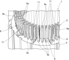
- FIG. 1 is a perspective view of a stator supported by a support jig according to an embodiment of the present invention.
- FIG. 2 is an enlarged perspective view showing a portion of FIG.
- FIG. 3 is a perspective view of the stator supported by a support jig, showing the protruding portions of the segment coil before being bent.
- FIG. 4 is an enlarged perspective view showing a portion of FIG. 5(A) to (F) are cross-sectional views showing a method for manufacturing a stator.
- FIG. 6A is a cross-sectional view showing a twisting device and a restraining jig according to an embodiment of the present invention
- FIG. 6B is an enlarged view of a portion of FIG. 6A.
- FIG. 7 is a perspective view showing the stator core and a restraining jig.
- FIG. 8 is an enlarged perspective view showing a portion of FIG.
- FIG. 9 is a perspective view showing the restraining jig of FIG.
- FIG. 10 is an exploded perspective view of the restraining jig of FIG.
- FIG. 11 is a plan view of the restraining jig of FIG.
- FIG. 12 is a front view of the restraining jig of FIG. 9 as viewed from a radial direction.
- FIG. 13 is a perspective view showing the twisting process.
- FIG. 14 is an enlarged cross-sectional view of the periphery of the groove in FIG.
- the goal of suppressing twisting that occurs when bending the protruding parts of the segment coil in the circumferential direction is achieved by using a restraining jig that allows bending while restraining the protruding parts in the radial direction.
- the manufacturing method of the stator 1 is to manufacture a stator 1 in which the protruding portion 11 of the segment coil 9, which protrudes in the axial direction from the stator core 3 that holds the segment coil 9, is bent in the circumferential direction.
- a restraining jig 19 is positioned between the bases 11a in the axial direction of the protruding portions 11 that are adjacent in the circumferential direction before bending.
- the restraining jig 19 has grooves 25 that correspond to the bases 11a that are adjacent in the circumferential direction.
- the tip 9a of the protrusion 11 is displaced circumferentially relative to the stator core 3, and the base 11a of the protrusion 11 is inserted into the groove 25 of the adjacent restraining jig 19 to restrain the protrusion 11 from the radial direction of the stator core 3, thereby bending the protrusion 11.
- the restraining jig 19 is made of an insulating material such as resin, it does not need to be removed, but if it is to be removed, it is preferable to use a spacer 23.
- the restraining jig 19 has a jig body 21 having a groove 25 stacked on top of the spacer 23 which is movable in the radial direction.
- the spacer 23 is removed radially outward after bending the protrusion 11.
- the jig body 21 is moved axially toward the stator core 3 in the space S created by removing the spacer 23, and then the base 11a of the protrusion 11 is pulled out of the groove 25 and removed radially outward.
- the restraining jig 19 can take various forms, but in one embodiment, it has a jig body 21 and a groove 25.
- the jig body 21 is positioned between the bases 11a of the circumferentially adjacent protrusions 11 in the axial direction.
- the grooves 25 are provided in the jig body 21.
- the restraining jig 19 may be provided with a spacer 23 as described above.
- the grooves 25 may be provided on both circumferential sides of the jig body 21. In this case, the groove 25 on one circumferential side may be radially offset from the groove 25 on the other circumferential side.
- the jig body 21 can have any planar shape, but may be sector-shaped when viewed from above. In this case, it is preferable that the outer peripheries 21a of the jig body 21 abut against each other in the circumferential direction.
- FIG. 1 is a perspective view of a stator supported by a support jig according to an embodiment of the present invention
- Fig. 2 is an enlarged perspective view of a part of Fig. 1 .
- the rotating electric machine is configured as a three-phase (U-phase, V-phase, W-phase) eight-pole AC permanent magnet synchronous motor that drives the drive wheels of an electric vehicle (not shown), for example, and generates electricity using the regenerative braking force from the drive wheels.
- Fig. 1 shows the state in which the stator coil 5 is assembled into the stator core 3 and supported by the support jig 7. In the state shown in Fig. 1, the protruding portion 11 including the coil end 9a of each segment coil 9 is bent.
- stator coil ends 9a are joined by welding to form the stator coil 5.
- the coil ends 9a are then coated with an insulating paint, and the stator coil 5 is sealed with resin to form the stator 1 for the rotating electric machine.
- the following description will refer to the stator 1 as shown in FIG. 1.
- the stator 1 includes a stator core 3 and a stator coil 5.
- the stator core 3 is formed, for example, by laminating a number of annular electromagnetic steel plates.
- the stator coil 5 is provided on the stator core 3 for three phases and is configured to have a wave-wound shape.
- the stator coil 5 is formed of a number of segment coils 9.
- the stator core 3 has multiple slots 3a spaced at equal intervals in the circumferential direction (the direction of rotation of the rotating electric machine). Segment coils 9 are inserted into the slots 3a with insulating paper 13 between them. This allows the multiple segment coils 9 to be held in place by the stator core 3.
- the multiple segment coils 9 are each formed in a U-shape, for example a hairpin shape, and are assembled in the circumferential direction around the stator core 3.
- the segment coils 9 are arranged in the circumferential direction, and are shifted to the adjacent layer at the apex of the hairpin shape. Note that the apex of the hairpin shape is hidden by the support jig 7 on the underside of Figure 1, and is not shown in the illustration.
- the segment coil 9 is made of, for example, a flat wire with a rectangular cross section.
- the cross-sectional shape of the segment coil 9 is not particularly limited.
- This segment coil 9 has a protrusion 11 including a coil end 9a without an insulating layer, which protrudes in the axial direction from the stator core 3.
- the axial direction refers to the direction along the axis of the stator core 3.
- the insulating layer is formed on the entire portion of the segment coil 9 except for the coil end 9a.
- the protruding portion 11 includes a portion that is inclined with respect to the axial direction. Therefore, the protrusion here means that the coil end 9a, which is the tip of the protruding portion 11, and the base portion 11a are misaligned in the axial direction.
- the base 11a refers to the area of the protruding portion 11 that is adjacent in the circumferential direction to the restraining jig 19 described below.
- the protruding portion 11 is twisted and bent in the circumferential direction. Therefore, the protruding portion 11 is the tip area where bending is performed on the hairpin-shaped leg of the segment coil 9.
- the sets of coil ends 9a between adjacent layers are joined by welding with the front of one coil end 9a facing the back of the other coil end 9a in the radial direction.
- Multiple joined sets of coil ends 9a are arranged in the circumferential and radial directions on the stator core 3.
- the circumferential and radial directions refer to the direction along the outer periphery and the direction along the diameter of the stator core 3, respectively.
- FIG. 3 is a perspective view of a stator supported by a support jig showing the state before bending of the protruding portion of the segment coil.
- Fig. 4 is an enlarged perspective view showing a part of the stator core of Fig. 3.
- Figs. 5(A) to (F) are cross-sectional views showing a manufacturing method of a stator.
- Fig. 6(A) is a cross-sectional view showing a twisting device and a restraining jig
- Fig. 6(B) is an enlarged view of a part of Fig. 6(A).
- the protruding portion 11 of the segment coil 9 held by the stator core 3 as shown in Figures 3 and 4 is bent in the circumferential direction as shown in Figures 1 and 2 by twisting.
- the bent protruding portion 11 is joined to the coil end 9a that will become a set in a subsequent process.
- the bent protrusion 11 has 14 layers, from the 1st layer on the outermost circumference to the 14th layer on the innermost circumference in the radial direction, as shown in Figures 5(A) to (F).
- Figures 1 to 4 show the protrusion 11 as having 6 layers, and show the same configuration as Figure 5(A) except for the number of layers.
- the protrusion 11 will be explained as having 14 layers, as shown in Figure 5, while also referring to Figures 1 to 4, which show 6 layers.
- the bending of the protrusions 11 is performed in each layer by restraining the coil end 9a of the protrusions 11 along the axial direction while moving them relative to the stator core 3 in the circumferential direction.
- the coil end 9a is restrained and moved in the circumferential direction by, for example, the annular twisting jigs 15a and 15b shown in FIG. 6.
- the twisting jigs 15a and 15b may have multiple teeth 17 in the circumferential direction.
- twisting jigs 15a and 15b move down to circumferentially restrain the coil end 9a, which is the tip of the protrusion 11, between adjacent teeth 17.
- This circumferential restraint is achieved by axially inserting the coil end 9a between adjacent teeth 17 in the circumferential direction (left side of Figure 6(A)).
- the twisting jigs 15a and 15b are displaced circumferentially relative to the stator core 3 to bend the protrusion 11.
- various types of twisting jigs 15a and 15b can be used as long as they can restrain the coil end 9a of the protrusion 11 and move it circumferentially.
- the bending of the protrusions 11 of the first layer, which is the outermost periphery, and the protrusions 11 of the next second layer are performed simultaneously by rotating a pair of twisting jigs 15a and 15b in opposite circumferential directions. After bending, the twisting jigs 15a and 15b are raised (right side of Figure 6(A)).
- the bending of the protrusions 11 of the first to fourteenth layers, two at a time is performed simultaneously, such as the third and fourth layers, the fifth and sixth layers.
- the bending of the protrusions 11 may be performed individually for each layer.
- a restraining jig 19 is used to prevent twisting of the protrusion 11, as shown in Figures 5 (A) to (F).
- the segment coil 9 is held on the stator core 3.
- the protrusions 11 protrude from the stator core 3 in the axial direction and are supported on the support jig 7.
- radial gaps are formed between the protrusions 11 of adjacent layers. This gap makes it easier to bend the protrusions in the circumferential direction.
- the restraining jig 19 is positioned between the bases 11a in the axial direction of the protrusions 11 that are adjacent in the circumferential direction of the stator core 3.
- Figure 5(B) shows the state in which the restraining jig 19 is disposed between the protrusion 11 on the front side (not shown) and the protrusion 11 on the rear side (shown).
- the restraining jig 19 is positioned between the bases 11a from the radial direction, but the insertion direction is free and it is also possible to position it from the axial direction, for example.
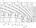
- Figure 7 is a perspective view showing the stator core 3 and the restraining jig 19.
- Figure 8 is an enlarged perspective view showing a portion of Figure 7.
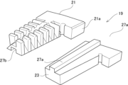
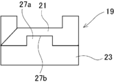
- Figures 9 to 12 are a perspective view, an exploded perspective view, a plan view, and a front view seen from the radial direction, showing the restraining jig 19 of Figure 7.
- the restraint jig 19 of this embodiment includes a jig body 21 and a spacer 23, as shown in Figures 7 to 12. Note that for convenience, the protrusion 11 is not shown in Figures 7 and 8.
- the jig body 21 is sector-shaped in plan view, and corresponds to the shape between the circumferentially adjacent protrusions 11 or their bases 11a.
- the planar shape of the jig body 21 can be set arbitrarily.
- the outer periphery 21a of the jig body 21 is located between the bases 11a of adjacent protrusions 11 and is positioned radially outward from the layer of the first outermost protrusion 11.
- This outer periphery 21a extends to one side in the circumferential direction and abuts against the outer periphery 21a of the adjacent jig body 21. Therefore, the jig body 21 is configured such that the outer peripheries 21a abut against each other in the circumferential direction. Due to this abutment, the jig body 21 is positioned in the circumferential direction.
- the jig body 21 is provided with a groove 25.
- the groove 25 is provided as a groove corresponding to the bases 11a adjacent in the circumferential direction when the restraining jig 19 is positioned between the bases 11a of the protrusions 11 adjacent in the circumferential direction.
- the groove 25 is arranged along the circumferential direction with respect to the bases 11a of the protrusions 11 adjacent in the circumferential direction.
- the groove 25 can be formed as an approximately linear groove in the circumferential direction, an arc-shaped groove along the circumferential direction, or the like.
- the groove 25 located on one circumferential side and the groove 25 located on the other circumferential side are arranged with a radial offset, and correspond to the base 11a of the protrusion 11 located on one side and the other side in the circumferential direction, respectively.
- the groove 25 on one circumferential side is provided from the edge of one circumferential side to the center of the jig body 21 in the circumferential direction.
- the groove 25 on the other circumferential side is provided from the edge of the other circumferential side to the center of the jig body 21 in the circumferential direction.
- Each groove 25 is defined by a radial wall 25a.
- the wall 25a extends approximately linearly in the circumferential direction in a plan view, but may have other planar shapes such as a cylindrical shape.
- the distance between the wall 25a corresponds to the radial dimension of the protruding portion 11 of the segment coil 9 before bending.
- the radial dimension of the groove 25 is set to be the same as or slightly larger than the radial dimension of the protruding portion 11 of the segment coil 9.
- each groove 25 is inclined in the axial direction toward the outside in the circumferential direction so as to gradually approach the stator core 3.
- the outside in the circumferential direction is the edge side on one side of the groove 25 on one side in the circumferential direction, and the edge side on the other side of the groove 25 on the other side in the circumferential direction.
- the spacer 23 stacks the jig body 21 and is movable in the radial direction.
- the spacer 23 is plate-shaped and has the same contour as the jig body 21 in plan view. Therefore, the spacer 23 overlaps the jig body 21 while being positioned between the jig body 21 and the stator core 3 in the axial direction. Note that the shape of the spacer 23 is not important as long as it allows the jig body 21 to be stacked.
- circumferential misalignment is prevented between the spacer 23 and the jig body 21 by a convex portion 27a and a concave portion 27b along the radial direction.
- One of the convex portion 27a and the concave portion 27b (in this embodiment, the convex portion 27a) is provided on the spacer 23, and the other (in this embodiment, the concave portion 27b) is provided on the jig body 21.
- the convex portion 27a and the concave portion 27b engage with each other so as to be freely slidable in the radial direction.
- the convex portion 27a may be provided over the entire radial direction, but it is also possible to provide it over only a portion of the radial direction.
- FIG. 5(C) shows the state in which the protrusion 11 on the front side, which is not shown in FIG. 5(B), is bent by the twisting process and engages with the restraining jig 19.
- additional restraining jigs 29a to 29c are positioned at each part as shown in FIG. 6 to perform the twisting process.
- the additional restraining jigs 29a to 29c are positioned radially inside and outside the protrusion 11, and between adjacent sets of coil ends 9a.
- the additional restraining jigs 29a to 29c may be omitted.
- the radially inner restraining jig 29a is disk-shaped and attached to a shaft portion 30 that axially passes through the center of the stator core 3, and its outer peripheral surface abuts radially against the protruding portion 11 of the innermost layer.
- the radially outer restraining jig 29b is formed in a ring shape, and its inclined inner peripheral surface abuts against the protruding portion 11 of the outermost layer from the radial outside.
- the restraining jig 29c is formed in a ring shape and is located in the gap between a set of coil ends 9a that are bent at the same time and an adjacent set of coil ends 9a.
- a ring-shaped jig holder 31 engages the outer periphery of the restraining jig 29b and the restraining jig 19.
- the pair of twisting jigs 15a and 15b that restrain the coil end 9a of the protrusion 11 are rotated in opposite directions in the circumferential direction. This allows the coil end 9a to be twisted two layers at a time at the same time.
- Figure 13 is a perspective view showing the twisting process.
- Figure 14 is an enlarged cross-sectional view of the groove area in Figure 13. Note that Figure 13 shows the twisting process of the innermost 14th and 13th layers.
- the base 11a of the protrusion 11 is restrained from the radial direction by the wall portion 25a.
- the restraint is achieved by engaging both radial side surfaces of the base 11a of the protrusion 11 with the wall portion 25a. Therefore, while the base 11a of the protrusion 11 is bent, the base 11a of the protrusion 11 is prevented from twisting around the axis as it is bent.
- a restraining jig 29c is further provided between the sets of coil ends 9a, so that the twisting of the protrusion 11 can be suppressed more reliably.
- the protrusion 11 is restrained from the inside and outside in the radial direction by restraining jigs 29a and 29b, so twisting of the protrusion 11 can be more reliably suppressed.
- the protrusion 11 can be bent in the circumferential direction while suppressing twisting of the protrusion 11, including the base 11a. After bending of the protrusion 11 is completed, each of the bent protrusions 11 is engaged with the groove 25 of the restraining jig 19.
- the restraining jig 19 can be removed as shown in Figures 5(D) to (F). If the restraining jig 19 is made of an insulating material such as resin, it does not need to be removed and it can form part of the stator 1. In this case, the restraining jig 19 may be formed integrally with the jig body 21 and the spacer 23.
- the additional restraining jigs 29a and 29b and the jig holder 31 can be removed by disassembly.
- the additional restraining jig 29c can be removed by simply pulling it out in the axial direction.
- the restraining jig 19 is positioned between the bases 11a in the axial direction of the protrusions 11 adjacent in the circumferential direction.
- the restraining jig 19 has grooves 25 corresponding to the bases 11a adjacent in the circumferential direction. Then, the coil ends 9a, which are the tips of the protrusions 11, are displaced in the circumferential direction relative to the stator core 3, and the bases 11a of the protrusions 11 are inserted into the grooves 25 of the adjacent restraining jigs 19, and the protrusions 11 are bent while being restrained from the radial direction of the stator core 3.
- the radial constraint provided by the groove 25 also serves to position the protrusion 11 in the radial direction, allowing the protrusion 11 to be bent reliably.
- the restraining jig 19 is constructed by stacking a jig body 21 having a groove 25 on a spacer 23 that is movable in the radial direction.
- the spacer 23 is removed radially outward after bending the protrusion 11, and the jig body 21 is moved axially toward the stator core 3 in the space S created by removing the spacer 23, and the base 11a is removed from the groove 25 and removed radially outward.
- the restraining jig 19 can be easily and reliably removed from the stator 1 with the protruding portion 11 bent.
- the material of the restraining jig 19 can be set as desired.
- the spacer 23 can also be removed radially inward depending on its planar shape, such as by making the planar shape a rectangular plate or rod.
- the restraining jig 19 is made of an insulating material such as resin, there is no need to remove it, making manufacturing easier.
- the spacer 23 has a simple structure that stacks the jig body 21 and allows it to move freely in the radial direction, making it easy to remove.
- the grooves 25 are provided on both sides of the jig body 21 in the circumferential direction, and the groove 25 on one side in the circumferential direction is radially offset from the groove 25 on the other side in the circumferential direction. Therefore, when the protrusions 11 of radially adjacent layers are bent in the circumferential direction in reverse, the twisting of the protrusions 11 of the adjacent layers can be suppressed by the grooves 25 on both sides of the circumferential direction of the jig body 21.
- the groove 25 also has a bottom surface 25b that slopes gradually in the axial direction toward the stator core 3 as it moves outward in the circumferential direction, becoming deeper as it moves outward in the circumferential direction.
- the jig body 21 is sector-shaped in plan view, and the outer periphery 21a abuts against each other in the circumferential direction. This makes it easy to install the jig body 21 on the cylindrical stator core 3.
Landscapes
- Engineering & Computer Science (AREA)
- Manufacturing & Machinery (AREA)
- Power Engineering (AREA)
- Manufacture Of Motors, Generators (AREA)
Abstract
Description
図1は、本発明の実施例に係り、支持治具に支持されたステーターの斜視図である。図2は、図1の一部を示す拡大斜視図である。
図3は、セグメントコイルの突出部の折り曲げ前を示す支持治具に支持されたステーターの斜視図である。図4は、図3のステーターコアの一部を示す拡大斜視図である。図5(A)~(F)は、ステーターの製造方法を示す断面図である。図6(A)は、ひねり加工装置及び拘束治具を示す断面図であり、図6(B)は、図6(A)の一部の拡大図である。
3 ステーターコア
9 セグメントコイル
9a コイルエンド(先端)
11 突出部
11a 基部
19 拘束治具
21 治具本体
21a 外周部
23 スペーサー
25 溝
25b 底面
S スペース
Claims (7)
- セグメントコイルを保持するステーターコアから軸方向に突出する前記セグメントコイルの突出部が周方向に折り曲げられたステーターの製造方法であって、
前記周方向に隣接する前記突出部の前記軸方向における基部間に拘束治具を位置させ、前記拘束治具が前記周方向で隣接する前記基部に対応した溝を有し、
前記突出部の先端を前記ステーターコアに対して前記周方向へ相対的に変位させ、前記突出部の前記基部をそれぞれ隣接する前記拘束治具の溝に入れ込んで前記ステーターコアの径方向から拘束しつつ前記突出部を折り曲げる、
ステーターの製造方法。 - 請求項1のステーターの製造方法であって、
前記拘束治具は、前記径方向に移動自在なスペーサー上に前記溝を有する治具本体が積層されて構成され、
前記スペーサーを、前記突出部の折り曲げ後に前記径方向の外側に取り外し、
前記治具本体を、前記スペーサーの取外しによるスペースで前記ステーターコア側に前記軸方向で移動させて前記溝から前記基部を抜き出した後に前記径方向の外側に取り外す、
ステーターの製造方法。 - セグメントコイルを保持するステーターコアから軸方向に突出する前記セグメントコイルの突出部を周方向に折り曲げる際に用いられる拘束治具であって、
前記周方向に隣接する前記突出部の前記軸方向における基部間に位置される治具本体と、
前記治具本体に設けられ前記治具本体が前記基部間に位置した状態で前記周方向で隣接する前記基部に対応した溝とを有し、
前記突出部の折り曲げ時に前記突出部の前記基部をそれぞれ隣接する溝に入れ込まれて前記ステーターコアの径方向から拘束する、
拘束治具。 - 請求項3の拘束治具であって、
前記治具本体を積層させると共に前記径方向に移動自在なスペーサーを備えた、
拘束治具。 - 請求項3又は4の拘束治具であって、
前記溝は、前記治具本体の前記周方向の両側に設けられ、前記周方向の一側の溝は、前記周方向の他側の溝に対して前記径方向にずれている、
拘束治具。 - 請求項5の拘束治具であって、
前記溝は、底面が前記周方向の外側へ向けて前記軸方向で漸次ステーターコア側に近接するように傾斜した、
拘束治具。 - 請求項3又は4の拘束治具であって、
前記治具本体は、平面視において扇形であり、外周部が前記周方向で相互に当接する、
拘束治具。
Priority Applications (4)
| Application Number | Priority Date | Filing Date | Title |
|---|---|---|---|
| CN202480043277.4A CN121444323A (zh) | 2023-06-30 | 2024-06-17 | 定子的制造方法以及约束夹具 |
| JP2025529656A JPWO2025004886A1 (ja) | 2023-06-30 | 2024-06-17 | |
| EP24831749.7A EP4738668A1 (en) | 2023-06-30 | 2024-06-17 | Stator manufacturing method and restraint jig |
| MX2025015329A MX2025015329A (es) | 2023-06-30 | 2025-12-16 | Metodo de fabricacion del estator y plantilla de sujecion. |
Applications Claiming Priority (2)
| Application Number | Priority Date | Filing Date | Title |
|---|---|---|---|
| JP2023-108051 | 2023-06-30 | ||
| JP2023108051 | 2023-06-30 |
Publications (1)
| Publication Number | Publication Date |
|---|---|
| WO2025004886A1 true WO2025004886A1 (ja) | 2025-01-02 |
Family
ID=93938986
Family Applications (1)
| Application Number | Title | Priority Date | Filing Date |
|---|---|---|---|
| PCT/JP2024/021875 Ceased WO2025004886A1 (ja) | 2023-06-30 | 2024-06-17 | ステーターの製造方法及び拘束治具 |
Country Status (5)
| Country | Link |
|---|---|
| EP (1) | EP4738668A1 (ja) |
| JP (1) | JPWO2025004886A1 (ja) |
| CN (1) | CN121444323A (ja) |
| MX (1) | MX2025015329A (ja) |
| WO (1) | WO2025004886A1 (ja) |
Citations (5)
| Publication number | Priority date | Publication date | Assignee | Title |
|---|---|---|---|---|
| JP2003143791A (ja) * | 2001-11-02 | 2003-05-16 | Toyota Motor Corp | 回転電機のステータ |
| JP2003259613A (ja) * | 2002-02-27 | 2003-09-12 | Denso Corp | 回転電機の固定子巻線の製造方法 |
| JP2006223058A (ja) * | 2005-02-10 | 2006-08-24 | Toyota Motor Corp | ステータ構造 |
| JP2017112749A (ja) * | 2015-12-17 | 2017-06-22 | アイシン・エィ・ダブリュ株式会社 | ステータの組立方法およびステータ |
| JP2023073670A (ja) * | 2021-11-16 | 2023-05-26 | 本田技研工業株式会社 | コイル挿入ガイド装置 |
-
2024
- 2024-06-17 CN CN202480043277.4A patent/CN121444323A/zh active Pending
- 2024-06-17 JP JP2025529656A patent/JPWO2025004886A1/ja active Pending
- 2024-06-17 EP EP24831749.7A patent/EP4738668A1/en active Pending
- 2024-06-17 WO PCT/JP2024/021875 patent/WO2025004886A1/ja not_active Ceased
-
2025
- 2025-12-16 MX MX2025015329A patent/MX2025015329A/es unknown
Patent Citations (5)
| Publication number | Priority date | Publication date | Assignee | Title |
|---|---|---|---|---|
| JP2003143791A (ja) * | 2001-11-02 | 2003-05-16 | Toyota Motor Corp | 回転電機のステータ |
| JP2003259613A (ja) * | 2002-02-27 | 2003-09-12 | Denso Corp | 回転電機の固定子巻線の製造方法 |
| JP2006223058A (ja) * | 2005-02-10 | 2006-08-24 | Toyota Motor Corp | ステータ構造 |
| JP2017112749A (ja) * | 2015-12-17 | 2017-06-22 | アイシン・エィ・ダブリュ株式会社 | ステータの組立方法およびステータ |
| JP2023073670A (ja) * | 2021-11-16 | 2023-05-26 | 本田技研工業株式会社 | コイル挿入ガイド装置 |
Also Published As
| Publication number | Publication date |
|---|---|
| JPWO2025004886A1 (ja) | 2025-01-02 |
| MX2025015329A (es) | 2026-02-03 |
| EP4738668A1 (en) | 2026-05-06 |
| CN121444323A (zh) | 2026-01-30 |
Similar Documents
| Publication | Publication Date | Title |
|---|---|---|
| EP3211772B1 (en) | Stator production method and coil | |
| CN102835004A (zh) | 回转电机 | |
| JP6288316B2 (ja) | ステータの組立方法およびステータの組立装置 | |
| JP5177512B2 (ja) | インナーロータ型回転電機の分割コア型ステータの組み立て方法 | |
| JP2017112749A (ja) | ステータの組立方法およびステータ | |
| JP4326932B2 (ja) | 固定子とその製造方法 | |
| CN118104111A (zh) | 用于轴向磁通电机的定子主体的组装方法 | |
| JP2017085775A (ja) | 端部加工装置 | |
| JP5626575B2 (ja) | 回転電機及びその固定子並びに製造方法 | |
| WO2025004886A1 (ja) | ステーターの製造方法及び拘束治具 | |
| JP6351861B2 (ja) | 電機子の製造方法 | |
| US20250167642A1 (en) | Apparatus for manufacturing stator, method for manufacturing stator, and stator | |
| JP2013118764A (ja) | ステータ製造方法及びステータ製造装置 | |
| JP2019126195A (ja) | ステータの組立方法 | |
| JP2010239718A (ja) | ステータの製造方法及び製造装置 | |
| JP4151344B2 (ja) | インシュレータ及び該インシュレータを備えたモータ | |
| EP4716074A1 (en) | Method and device for manufacturing stator | |
| WO2019065103A1 (ja) | ステータおよびステータの製造方法 | |
| WO2025070347A1 (ja) | ステーターの製造方法及び装置 | |
| JP6912252B2 (ja) | 固定子および電動機 | |
| EP4716073A1 (en) | Manufacturing method for stator, twisting machining device, and twisting jig assembly | |
| CN121816689A (zh) | 用于对电机的转子的绕组进行压实的方法以及压实工具 | |
| WO2026048453A1 (ja) | ステータ、モータ及びステータの製造方法 | |
| JP4468112B2 (ja) | 3相回転電機およびその製造方法 | |
| KR20240091425A (ko) | 전기자동차 모터용 스테이터 |
Legal Events
| Date | Code | Title | Description |
|---|---|---|---|
| 121 | Ep: the epo has been informed by wipo that ep was designated in this application |
Ref document number: 24831749 Country of ref document: EP Kind code of ref document: A1 |
|
| ENP | Entry into the national phase |
Ref document number: 2025529656 Country of ref document: JP Kind code of ref document: A |
|
| WWE | Wipo information: entry into national phase |
Ref document number: 2025529656 Country of ref document: JP |
|
| WWE | Wipo information: entry into national phase |
Ref document number: MX/A/2025/015329 Country of ref document: MX |
|
| WWE | Wipo information: entry into national phase |
Ref document number: 2024831749 Country of ref document: EP |
|
| NENP | Non-entry into the national phase |
Ref country code: DE |
|
| ENP | Entry into the national phase |
Ref document number: 2024831749 Country of ref document: EP Effective date: 20260130 |
|
| WWP | Wipo information: published in national office |
Ref document number: MX/A/2025/015329 Country of ref document: MX |
|
| ENP | Entry into the national phase |
Ref document number: 2024831749 Country of ref document: EP Effective date: 20260130 |