WO2025004831A1 - モータ制御装置 - Google Patents
モータ制御装置 Download PDFInfo
- Publication number
- WO2025004831A1 WO2025004831A1 PCT/JP2024/021532 JP2024021532W WO2025004831A1 WO 2025004831 A1 WO2025004831 A1 WO 2025004831A1 JP 2024021532 W JP2024021532 W JP 2024021532W WO 2025004831 A1 WO2025004831 A1 WO 2025004831A1
- Authority
- WO
- WIPO (PCT)
- Prior art keywords
- motor
- command value
- axis
- control device
- voltage
- Prior art date
- Legal status (The legal status is an assumption and is not a legal conclusion. Google has not performed a legal analysis and makes no representation as to the accuracy of the status listed.)
- Ceased
Links
Images

Classifications
-
- H—ELECTRICITY
- H02—GENERATION; CONVERSION OR DISTRIBUTION OF ELECTRIC POWER
- H02P—CONTROL OR REGULATION OF ELECTRIC MOTORS, ELECTRIC GENERATORS OR DYNAMO-ELECTRIC CONVERTERS; CONTROLLING TRANSFORMERS, REACTORS OR CHOKE COILS
- H02P21/00—Arrangements or methods for the control of electric machines by vector control, e.g. by control of field orientation
- H02P21/05—Arrangements or methods for the control of electric machines by vector control, e.g. by control of field orientation specially adapted for damping motor oscillations, e.g. for reducing hunting
-
- H—ELECTRICITY
- H02—GENERATION; CONVERSION OR DISTRIBUTION OF ELECTRIC POWER
- H02P—CONTROL OR REGULATION OF ELECTRIC MOTORS, ELECTRIC GENERATORS OR DYNAMO-ELECTRIC CONVERTERS; CONTROLLING TRANSFORMERS, REACTORS OR CHOKE COILS
- H02P29/00—Arrangements for regulating or controlling electric motors, appropriate for both AC and DC motors
- H02P29/50—Reduction of harmonics
-
- H—ELECTRICITY
- H02—GENERATION; CONVERSION OR DISTRIBUTION OF ELECTRIC POWER
- H02P—CONTROL OR REGULATION OF ELECTRIC MOTORS, ELECTRIC GENERATORS OR DYNAMO-ELECTRIC CONVERTERS; CONTROLLING TRANSFORMERS, REACTORS OR CHOKE COILS
- H02P6/00—Arrangements for controlling synchronous motors or other dynamo-electric motors using electronic commutation dependent on the rotor position; Electronic commutators therefor
- H02P6/10—Arrangements for controlling torque ripple, e.g. providing reduced torque ripple
Definitions
- the present invention relates to a motor control device that suppresses torque ripple generated by a motor during motor control.
- Patent Document 1 An example of a conventional device that suppresses torque ripple in a motor to reduce vibration is the technology described in Patent Document 1.
- the device described in Patent Document 1 creates a table relating to the amplitude and phase of the torque ripple according to the torque generated by the motor, and by referring to this table, calculates a modified torque ripple compensation value that suppresses the amplitude and phase of the torque ripple, and superimposes it on the command value. This modification makes it possible to suppress torque ripple at frequencies that exceed the torque control band.
- An object of the present invention is to provide a motor control device that can simultaneously shorten the time required to design and adjust the amount of correction of amplitude and phase according to the response characteristics, and ensure the effect of suppressing torque ripple.
- the present invention uses a control system for the FB controller that has a robust response to changes in the motor constants, and individually corrects the phase and amplitude of the dq axis harmonic command values according to the rotation speed.
- the present invention is configured as follows:
- a motor control device that drives a motor using an inverter, comprising: a harmonic control command value calculation unit that determines a first harmonic control command value from a torque command value and the electrical angle of the motor; a response compensation unit that calculates a second harmonic control command value by performing response characteristic compensation on the first harmonic control command value according to the rotation speed of the motor; and a voltage command calculation unit that calculates a voltage command value based on a control command for outputting the torque of the torque command value and the second harmonic control command value.
- the present invention can provide a motor control device that can simultaneously reduce the time required to design and adjust the amount of amplitude and phase correction according to the response characteristics, while ensuring the effect of suppressing torque ripple.
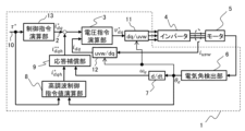
- FIG. 1 is a schematic block diagram of a motor control device according to a first embodiment of the present invention
- 11 is a diagram showing a difference between an actual current and a detected current caused by a current detection delay.
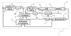
- FIG. FIG. 11 is a schematic block diagram of a motor control device according to a second embodiment of the present invention.
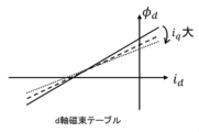
- FIG. 2 is a diagram illustrating conversion from a current to a magnetic flux.
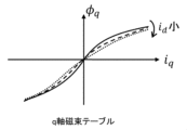
- FIG. 2 is a diagram illustrating conversion from a current to a magnetic flux.
- FIG. 1 is a functional block diagram showing the configuration of a motor control device 1 according to a first embodiment of the present invention.
- dq axis refers to the “d axis and q axis.”
- Xdq refers to the “vector quantity (Xd, Xq)”
- Xuvw refers to the “vector quantity (Xu, Xv, Xw).”
- uvw refers to the three phases of AC, i.e., "U phase, V phase, and W phase.”
- the motor control device 1 controls the speed and torque of the motor 5 by controlling the switching of the inverter 4 that supplies AC power to the motor 5.
- the motor control device 1 is configured with a processing device such as a microcomputer, and functions as each part by executing a specific program.
- the inverter 4 is a three-phase inverter whose main circuit is a three-phase full-bridge circuit composed of semiconductor switching elements such as IGBTs and MOSFETs.
- a three-phase AC synchronous motor which is a rotating machine, such as a permanent magnet synchronous motor, is used as the motor 5.
- the motor 5 is not limited to a synchronous machine, and an induction machine may be used.
- the motor 5 is not limited to a rotating machine, and a linear motor may be used.
- the motor 5 may have a power generation function.
- the voltage command calculation unit 3 generates a voltage command value v* dq according to the difference between the dq-axis current detection value i dq and the dq-axis current command value i * dq so that the dq-axis current detection value i dq matches the dq-axis current command value i * dq .
- the voltage command calculation unit 3 calculates a voltage command value v*dq using the dq-axis current command value i * dq (the d-axis current command value i * d and the q-axis current command value i * q ) in a configuration in which integrators are connected in series to the d and q axes of the motor inverse model of the following formula ( 1) .
- a variable with a t at the end of the L subscript representing inductance means dynamic inductance
- a variable without a t means static inductance.
- the voltage command calculation unit 3 is not limited to the configuration of this embodiment 1, and may use a control configuration obtained by equivalent transformation, or an approximation model that ignores terms with small effects. For example, if use in the magnetic saturation region is not expected, the dynamic inductance and static inductance can be treated as equivalent values, or an integrator and a motor inverse model can be combined to configure a PI controller and a non-interacting controller.
- the electrical angle detection unit 6 calculates and outputs the electrical angle ⁇ e based on a rotational position signal from a rotation sensor (not shown) provided in the motor 5.
- the rotation sensor can be a mechanical angle resolver, hall sensor, rotary encoder, etc. It can also be configured to estimate the electrical angle from the current and voltage using a general position sensorless control method.
- the electrical angular velocity calculation unit 7 calculates and outputs the electrical angular velocity ⁇ e based on a rotational position signal from a rotation sensor (not shown) included in the motor 5.
- the electrical angular velocity calculation unit 7 may be configured by a differentiator that differentiates the electrical angle ⁇ e output by the electrical angle calculation unit 6 to calculate the electrical angular velocity ⁇ e .
- the harmonic control command value calculation unit 8 outputs a first harmonic control command value i * dqh from the torque command value ⁇ * .
- the response compensation unit 9 has a response compensation table or a response compensation function, and outputs a second harmonic control command value i ** dqh obtained by correcting the first harmonic control command value i * dqh by the amount of correction of phase and amplitude calculated from the response compensation table or the response compensation function based on the electrical angular velocity ⁇ e.
- a voltage command value dq/three-phase axis converter 11 (shown as dq/uvw in FIG. 1 ) converts the voltage command value v * dq output from the voltage command calculation unit 3 into a three-phase voltage according to the electrical angle ⁇ e , and generates a signal for controlling the switching of the inverter 4.
- ⁇ ec instead of the electrical angle ⁇ e, ⁇ ec in which a delay required for the voltage command value to be actually reflected in the inverter 4 is compensated may be used.
- the measurement current three-phase/dq axis converter 12 converts the three-phase currents detected by the current sensors into dq axis currents i dq in accordance with ⁇ e .
- ⁇ ed that takes into account the current detection delay may be used instead of ⁇ e .
- the harmonic control command value calculation unit 8 receives the torque command value ⁇ * and calculates a first harmonic control command value i * dqh as shown in the following equation (2): where n indicates the order of the torque ripple.
- the dq axis currents I dq and ⁇ dq are obtained in advance by analysis or testing, and can be obtained from a table with the torque command value ⁇ * as an argument.
- ⁇ delay is a manipulated variable that advances the phase by the delay time that occurs between the detected current and the current actually flowing through the motor 5, and is calculated as nT delay ⁇ e , where T delay is the delay time.
- the dq-axis current detection values I dq and ⁇ dq are stored as complex coefficients, thereby making it possible to avoid phase discontinuity when referring to the table.
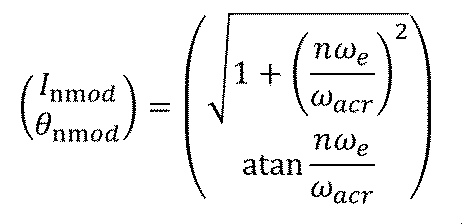
- the response compensation unit 9 calculates the electrical angular frequency of the torque ripple at n ⁇ e for the first harmonic control command value i * dqh . Furthermore, it calculates the amplitude correction amount I mod and the phase correction amount ⁇ mod corresponding to n ⁇ e from the two-dimensional table of amplitude correction and electrical angular frequency and the two-dimensional table of phase correction and each electrical frequency. Since the response is designed as a first-order lag system in this embodiment 1, these two-dimensional tables can also be implemented as a function of the following formula (3). However, in formula (3), ⁇ acr is the control response angular frequency.
- the second harmonic control command value i ** dqh is calculated by the following equation (4).
- the voltage command calculation unit 3 calculates a voltage command value v * dq from the second harmonic control command value i ** dqh , the final current command value calculated from the dq axis current command value i * dq , and the current measurement value.
- the torque response characteristics require the retention of amplitude and phase correction tables for the number of combinations of dq-axis control response characteristics, which takes time for design.
- the response characteristics are determined for each axis, so it is only necessary to prepare amplitude and phase correction tables or functions for each different control response angular frequency ⁇ acr, and the torque ripple suppression effect can be ensured while shortening the design man-hours.
- the torque ripple of a single frequency is the target in order to explain the operation, but it is also possible to deal with cases including torque ripple of multiple frequencies by performing the same operation for any order and adding up the results of all orders at the output stage of the response compensation unit 9.
- the response compensation unit 9 calculates the amplitude correction amount I mod and the phase correction amount ⁇ mod for each order.
- the first embodiment it is possible to provide a motor control device that can simultaneously reduce the time required to design and adjust the amount of correction of amplitude and phase according to the response characteristics and ensure the torque ripple suppression effect.
- Example 1 The differences from Example 1 will be explained using the block diagram of Example 2 shown in Figure 3.
- the second embodiment includes a converter 100 that calculates a dq-axis current command value 2 (i * dq ) from a control command calculation unit 13 based on a torque command value 10 ( ⁇ * ) and converts the dq-axis current command value 2 (i * dq ) into a magnetic flux command value ⁇ dq , a converter 101 that converts a measured current idq into a measured magnetic flux value ⁇ dq , a harmonic control command value calculation unit 8 that records a first harmonic control command value ⁇ * dqh calculated in advance from a harmonic current command value corresponding to the torque command value 10 ( ⁇ * ) using the following equation (5) and outputs the first harmonic control command value ⁇ *dqh from the torque command value 10 ( ⁇ * ) during control, a response compensation unit 9 that calculates a second harmonic control command value ⁇ ** dqh from the first harmonic control command value ⁇ * dqh and an electrical angular velocity ⁇ e, and a converter 102 that
- the voltage command calculation unit 3 calculates a voltage command value v * dq from ⁇ dqh and magnetic flux measurement values ⁇ dq (d-axis magnetic flux measurement value ⁇ d , q-axis magnetic flux measurement value ⁇ q ) using the motor inverse model of the following equation (6).
- the physical quantities of the first harmonic control command value ⁇ * dqh and the second harmonic control command value ⁇ ** dqh in the second embodiment are magnetic fluxes, unlike the currents in the first embodiment.
- fd in the following formula (5) is a relationship between the current and the magnetic flux obtained by a prior analysis or test, and is a function that depends on the currents of the dq axes, for example, as shown in Figures 4A and 4B.
- the converters 100 and 101 may use the same function, or in the case of tables, tables having different resolutions depending on the required accuracy for the command value and the measured value may be used.
- the function of the second embodiment will be explained by comparing it with the first embodiment.
- the inverse model of the motor can reduce the number of variables as shown in equation (6) compared to equation (1) for current. This not only provides the same effect as the first embodiment, but also makes it possible to reduce the number of searches and constant tables while taking into account nonlinearity due to magnetic saturation.
Landscapes
- Engineering & Computer Science (AREA)
- Power Engineering (AREA)
- Control Of Ac Motors In General (AREA)
Abstract
Description
本発明は、FB制御器にモータ定数の変化に対して応答がロバストな制御系を用い、dq軸の高調波指令値に対して回転数に応じた位相と振幅の修正を個別に行う。
図1は、本発明の実施例1であるモータ制御装置1の構成を示す機能ブロック図である。



次に、実施例2について説明する。


Claims (5)
- モータをインバータにより駆動するモータ制御装置であって、
トルク指令値と前記モータの電気角とから第1の高調波制御指令値を求める高調波制御指令値演算部と、
前記第1の高調波制御指令値に前記モータの回転数に応じた応答特性補償を行った第2の高調波制御指令値を計算する応答補償部と、
前記トルク指令値のトルクを出力するための制御指令と前記第2の高調波制御指令値に基づき、電圧指令値を演算する電圧指令演算部と、
を備えることを特徴とするモータ制御装置。 - 請求項1に記載のモータ制御装置であって、
前記高調波制御指令値演算部は、次数ごとに前記第1の高調波制御指令値を演算することを特徴とするモータ制御装置。 - 請求項1に記載のモータ制御装置であって、
前記応答補償部は、前記第1の高調波制御指令値の振幅と位相を次数ごとに補正することを特徴とするモータ制御装置。 - 請求項1に記載のモータ制御装置であって、
前記電圧指令演算部は、
Vdを前記モータのd軸電圧、Vqを前記モータのq軸電圧、Rを前記モータの巻線の抵抗値、Ldを前記モータ5d軸インダクタンス、Lqを前記モータのq軸インダクタンス、LdqおよびLqdを前記モータのd軸とq軸との干渉インダクタンス、Keを誘起電圧定数、Ldtを前記モータのd軸の動的インダクタンス、Lqtを前記モータのq軸の動的インダクタンス、LdqtおよびLqdtを前記モータのd軸とq軸との動的干渉インダクタンス、i*dをd軸電流指令値、i*qをq軸電流指令値、ωeを前記モータの電気角速度としたとき、以下の数式(1)、

- 請求項1に記載のモータ制御装置であって、
前記電圧指令演算部は、
Vdを前記モータのd軸電圧、Vqを前記モータのq軸電圧、Rを前記モータの巻線の抵抗値、Ldを前記モータのd軸インダクタンス、Lqを前記モータのq軸インダクタンス、LdqおよびLqdを前記モータのd軸とq軸との干渉インダクタンス、Keを誘起電圧定数、φdを前記モータのd軸の磁束計測値、φqを前記モータのq軸の磁束計測値、ωeを前記モータの電気角速度としたとき、以下の数式(6)、

Priority Applications (2)
| Application Number | Priority Date | Filing Date | Title |
|---|---|---|---|
| CN202480009983.7A CN120615275A (zh) | 2023-06-27 | 2024-06-13 | 电机控制装置 |
| DE112024000445.8T DE112024000445T5 (de) | 2023-06-27 | 2024-06-13 | Motorsteuervorrichtung |
Applications Claiming Priority (2)
| Application Number | Priority Date | Filing Date | Title |
|---|---|---|---|
| JP2023-105253 | 2023-06-27 | ||
| JP2023105253A JP2025005179A (ja) | 2023-06-27 | 2023-06-27 | モータ制御装置 |
Publications (1)
| Publication Number | Publication Date |
|---|---|
| WO2025004831A1 true WO2025004831A1 (ja) | 2025-01-02 |
Family
ID=93938894
Family Applications (1)
| Application Number | Title | Priority Date | Filing Date |
|---|---|---|---|
| PCT/JP2024/021532 Ceased WO2025004831A1 (ja) | 2023-06-27 | 2024-06-13 | モータ制御装置 |
Country Status (4)
| Country | Link |
|---|---|
| JP (1) | JP2025005179A (ja) |
| CN (1) | CN120615275A (ja) |
| DE (1) | DE112024000445T5 (ja) |
| WO (1) | WO2025004831A1 (ja) |
Families Citing this family (1)
| Publication number | Priority date | Publication date | Assignee | Title |
|---|---|---|---|---|
| CN120915177B (zh) * | 2025-10-09 | 2025-12-23 | 陕西立拓科源科技有限公司 | 一种降低转矩脉动的电机驱动器控制方法及系统 |
Citations (3)
| Publication number | Priority date | Publication date | Assignee | Title |
|---|---|---|---|---|
| JP2014011870A (ja) * | 2012-06-29 | 2014-01-20 | Denso Corp | 回転機の制御装置 |
| JP2016063649A (ja) * | 2014-09-18 | 2016-04-25 | 株式会社デンソー | モータ制御装置 |
| JP2019022299A (ja) * | 2017-07-14 | 2019-02-07 | 株式会社デンソー | 回転電機の駆動システム |
-
2023
- 2023-06-27 JP JP2023105253A patent/JP2025005179A/ja active Pending
-
2024
- 2024-06-13 DE DE112024000445.8T patent/DE112024000445T5/de active Pending
- 2024-06-13 CN CN202480009983.7A patent/CN120615275A/zh active Pending
- 2024-06-13 WO PCT/JP2024/021532 patent/WO2025004831A1/ja not_active Ceased
Patent Citations (3)
| Publication number | Priority date | Publication date | Assignee | Title |
|---|---|---|---|---|
| JP2014011870A (ja) * | 2012-06-29 | 2014-01-20 | Denso Corp | 回転機の制御装置 |
| JP2016063649A (ja) * | 2014-09-18 | 2016-04-25 | 株式会社デンソー | モータ制御装置 |
| JP2019022299A (ja) * | 2017-07-14 | 2019-02-07 | 株式会社デンソー | 回転電機の駆動システム |
Also Published As
| Publication number | Publication date |
|---|---|
| JP2025005179A (ja) | 2025-01-16 |
| CN120615275A (zh) | 2025-09-09 |
| DE112024000445T5 (de) | 2025-10-23 |
Similar Documents
| Publication | Publication Date | Title |
|---|---|---|
| KR100364014B1 (ko) | 교류전동기의 제어장치 | |
| JP4909797B2 (ja) | モータ制御装置 | |
| JP4674516B2 (ja) | 同期モータの磁極位置推定方法 | |
| KR101046802B1 (ko) | 교류 회전기의 제어 장치 및 이 제어 장치를 사용한 교류회전기의 전기적 정수 측정 방법 | |
| US20070085508A1 (en) | Method of estimating magnetic pole position in motor and apparatus of controlling the motor based on the estimated position | |
| JP7090812B2 (ja) | 交流回転電機の制御装置及び電動パワーステアリング装置 | |
| JP2010057217A (ja) | 電動機のトルク脈動抑制装置および抑制方法 | |
| KR102409792B1 (ko) | 영구 자석 동기 전동기의 제어 장치, 마이크로 컴퓨터, 전동기 시스템 및 영구 자석 동기 전동기의 운전 방법 | |
| JP3707528B2 (ja) | 交流電動機の制御方法およびその制御装置 | |
| JP5358679B2 (ja) | 三相交流電動機の駆動装置、駆動方法、三相交流電動機、および制御装置 | |
| JP2022131542A (ja) | インバータ制御装置およびインバータ制御装置の製造方法 | |
| JP5473289B2 (ja) | 永久磁石型同期モータの制御装置及び制御方法 | |
| JP7304891B2 (ja) | 回転機の制御装置および電動車両の制御装置 | |
| JP2010035352A (ja) | 同期電動機のロータ位置推定装置 | |
| EP4050788B1 (en) | Power conversion device | |
| JP2025005179A (ja) | モータ制御装置 | |
| JP3707659B2 (ja) | 同期電動機の定数同定方法 | |
| CN110785923A (zh) | 电机控制装置和电机控制方法 | |
| JP5444983B2 (ja) | 回転機の制御装置 | |
| WO2015186406A1 (ja) | 周期外乱自動抑制装置 | |
| WO2021054033A1 (ja) | モータ制御装置およびモータ制御方法 | |
| JP5106295B2 (ja) | 同期電動機のロータ位置推定装置 | |
| JP3674638B2 (ja) | 誘導電動機の速度推定方法および誘導電動機駆動装置 | |
| JP4038412B2 (ja) | ベクトル制御インバータ装置 | |
| JP2023007752A (ja) | 電動機駆動制御装置および該方法ならびに電動機駆動制御システム |
Legal Events
| Date | Code | Title | Description |
|---|---|---|---|
| 121 | Ep: the epo has been informed by wipo that ep was designated in this application |
Ref document number: 24831696 Country of ref document: EP Kind code of ref document: A1 |
|
| WWE | Wipo information: entry into national phase |
Ref document number: 202480009983.7 Country of ref document: CN |
|
| WWE | Wipo information: entry into national phase |
Ref document number: 112024000445 Country of ref document: DE |
|
| WWP | Wipo information: published in national office |
Ref document number: 202480009983.7 Country of ref document: CN |
|
| WWP | Wipo information: published in national office |
Ref document number: 112024000445 Country of ref document: DE |
|
| 122 | Ep: pct application non-entry in european phase |
Ref document number: 24831696 Country of ref document: EP Kind code of ref document: A1 |