WO2025004819A1 - 色変換シートならびにそれを含む光源ユニット、ディスプレイおよび照明装置 - Google Patents
色変換シートならびにそれを含む光源ユニット、ディスプレイおよび照明装置 Download PDFInfo
- Publication number
- WO2025004819A1 WO2025004819A1 PCT/JP2024/021454 JP2024021454W WO2025004819A1 WO 2025004819 A1 WO2025004819 A1 WO 2025004819A1 JP 2024021454 W JP2024021454 W JP 2024021454W WO 2025004819 A1 WO2025004819 A1 WO 2025004819A1
- Authority
- WO
- WIPO (PCT)
- Prior art keywords
- group
- color conversion
- conversion sheet
- light
- light source
- Prior art date
- Legal status (The legal status is an assumption and is not a legal conclusion. Google has not performed a legal analysis and makes no representation as to the accuracy of the status listed.)
- Ceased
Links
Images

Classifications
-
- F—MECHANICAL ENGINEERING; LIGHTING; HEATING; WEAPONS; BLASTING
- F21—LIGHTING
- F21S—NON-PORTABLE LIGHTING DEVICES; SYSTEMS THEREOF; VEHICLE LIGHTING DEVICES SPECIALLY ADAPTED FOR VEHICLE EXTERIORS
- F21S2/00—Systems of lighting devices, not provided for in main groups F21S4/00 - F21S10/00 or F21S19/00, e.g. of modular construction
-
- G—PHYSICS
- G02—OPTICS
- G02B—OPTICAL ELEMENTS, SYSTEMS OR APPARATUS
- G02B5/00—Optical elements other than lenses
- G02B5/20—Filters
-
- G—PHYSICS
- G09—EDUCATION; CRYPTOGRAPHY; DISPLAY; ADVERTISING; SEALS
- G09F—DISPLAYING; ADVERTISING; SIGNS; LABELS OR NAME-PLATES; SEALS
- G09F9/00—Indicating arrangements for variable information in which the information is built-up on a support by selection or combination of individual elements
Definitions
- the present invention relates to a color conversion sheet, as well as a light source unit, display, and lighting device that include the same.
- Color conversion refers to converting light from an illuminant into light with a longer wavelength; for example, blue light can be converted into green or red light.
- this composition with color conversion function into a sheet and combining it with, for example, a blue light source, it becomes possible to obtain the three primary colors of blue, green, and red from the blue light source, thereby making it possible to obtain white light.
- a white light source which combines a blue light source with a sheet with color conversion function, as a backlight unit and combining it with a liquid crystal drive section and a color filter, it becomes possible to create a full-color display.
- a white light source which combines a blue light source with a sheet with color conversion function, can also be used as it is as a white light source for LED lighting, etc.
- Patent Document 1 by reducing the difference in refractive index between the transparent resin and the dispersed particles in the wavelength conversion layer, it is possible to emit concentrated light without diffusing it.
- the blue light source itself has uneven light distribution, i.e., if there is a large difference in light intensity depending on the viewing angle, the light is emitted without being diffused, making it difficult to reflect the blue light isotropically. This causes a problem of large color unevenness depending on the viewing angle on the viewing side, i.e., the color is highly dependent on the angle.
- the reflectance of the wavelength conversion layer is increased to improve the uneven light distribution of such a blue light source, there is a problem in that sufficient brightness cannot be ensured.
- the present invention aims to provide a color conversion sheet that can produce displays, lighting devices, etc. with low color angle dependency and high brightness.
- the present invention has the following configuration.
- a color conversion sheet that converts incident light into light of a different wavelength from the incident light the color conversion sheet having a light extraction layer as its outermost layer, the light extraction layer having a surface roughness Ra of 0.05 ⁇ m to 2 ⁇ m, and an average total reflectance in the wavelength region of 440 nm to 470 nm on at least one surface of the color conversion sheet of 10% to 60%.
- the light-emitting material (a) and/or the light-emitting material (b) is an organic light-emitting material.
- R1 to R9 may be the same or different and are selected from hydrogen, an alkyl group, a cycloalkyl group, a heterocyclic group, an alkenyl group, a cycloalkenyl group, an alkynyl group, a hydroxyl group, a thiol group, an alkoxy group, an alkylthio group, an aryl ether group, an aryl thioether group, an aryl group, a heteroaryl group, a halogen, a cyano group, an aldehyde group, a carbonyl group, a carboxyl group, an oxycarbonyl group, a carbamoyl group, an amino group, a nitro group, a silyl group, a siloxanyl group, a boryl group, a phosphine oxide group, and a fused ring and an aliphatic ring formed between adjacent substituents.
- a light source unit comprising a light source and the color conversion sheet according to any one of [1] to [12].
- a display comprising the light source unit according to any one of [13] to [16].
- a lighting device comprising the light source unit according to any one of [13] to [16].
- the color conversion sheet of the present invention has the effect of having low color angle dependency and high brightness.
- the light source unit, display, and lighting device of the present invention use such a color conversion sheet, which makes it possible to have low color angle dependency and high brightness.
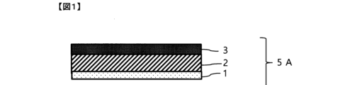
- FIG. 2 is a schematic cross-sectional view showing an example of the color conversion sheet of the present invention.
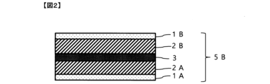
- FIG. 2 is a schematic cross-sectional view showing an example of the color conversion sheet of the present invention.
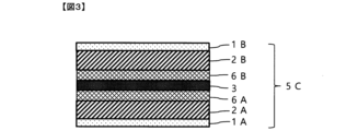
- FIG. 2 is a schematic cross-sectional view showing an example of the color conversion sheet of the present invention.
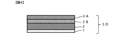
- FIG. 2 is a schematic cross-sectional view showing an example of the color conversion sheet of the present invention.
- FIG. 2 is a schematic cross-sectional view showing an example of the color conversion sheet of the present invention.
- FIG. 2 is a schematic cross-sectional view showing an example of a light source unit of the present invention.
- the color conversion sheet according to the embodiment of the present invention is a sheet that converts incident light into light having a wavelength different from that of the incident light, preferably into light having a wavelength longer than that of the incident light.
- Lambertian radiation refers to radiation based on Lambert's law of radiation, which means that the intensity of light emitted from a completely diffusive surface is proportional to the cosine of the angle between the normal to the surface and the observation direction. Light based on Lambertian radiation is said to look the same when viewed from any angle.
- the color conversion sheet according to the embodiment of the present invention has an average total reflectance of 10% to 60% in the wavelength region of 440 nm to 470 nm on at least one surface. This makes it possible to bring the incident blue light closer to Lambertian radiation. This makes it possible to reduce the angular dependence of blue and other colors that are wavelength-converted from it. From the viewpoint of achieving both brightness and angular dependence, the lower limit of the average total reflectance is preferably 30% or more.
- the upper limit of the average total reflectance is preferably 60% or less, and more preferably 45% or less.
- the surface with an average total reflectance of 10% to 60% in the wavelength range of 440 nm to 470 nm is the surface arranged on the light source side. This is because it is possible to make the blue light incident on the color conversion sheet from the light source closer to Lambertian radiation at the point of incidence.
- the color conversion sheet according to the embodiment of the present invention has a value of 3% ⁇ Rg1-Rg2 in the wavelength region of 520 nm to 580 nm, where Rg1 is the average total reflectance of the first surface and Rg2 is the average total reflectance of the second surface.
- Rg1 is the average total reflectance of the first surface
- Rg2 is the average total reflectance of the second surface.
- the surface with the larger average total reflectance is called the first surface
- the surface with the smaller average total reflectance is called the second surface.
- the average total reflectance measured from both surfaces is equal, either surface may be called the first surface. In such a case, for convenience, one of the surfaces is called the first surface and the opposite surface is called the second surface.
- the color conversion sheet according to the embodiment of the present invention When applying the color conversion sheet according to the embodiment of the present invention to a display or lighting device, it is preferable to arrange the color conversion sheet so that the first surface is the viewing side and the second surface is the light source side. With this arrangement, the reflection of light in the green region on the viewing side is significantly greater than that on the light source side, improving the green light emission efficiency and achieving higher brightness.
- Rg1-Rg2 There is no particular limit to the upper limit of Rg1-Rg2, but from the viewpoint of achieving both high brightness and angle dependency of color, it is preferable that it be 10% or less.
- the color conversion sheet according to the embodiment of the present invention satisfies 5% ⁇ Rb2-Rb1 ⁇ 13%.
- Rb2-Rb1 is 5% or more
- the reflection of light in the blue region on the light source side is sufficiently greater than that on the viewing side, so that light emitted from the blue light source can be reflected efficiently, thereby making it possible to reduce the angle dependency of color.
- Rb2-Rb1 is 13% or less
- the light reflection on the second surface side is in a moderate range, making it easier to achieve both angle dependency of color and high brightness.
- the total reflectance of the color conversion sheet can be measured in accordance with ASTM E1164.
- the color conversion sheet according to the embodiment of the present invention preferably comprises a light extraction layer, a color conversion layer, and a base layer. Details of each layer are described below.
- FIG. 1 is a schematic cross-sectional view showing a first example of a color conversion sheet according to an embodiment of the present invention.
- this first example of a color conversion sheet 5A is a laminate of a light extraction layer 1, a base layer 2, and a color conversion layer 3.
- the color conversion layer 3 is laminated on top of the base layer 2.
- FIG. 2 is a schematic cross-sectional view showing a second example of a color conversion sheet according to an embodiment of the present invention.
- the second example of color conversion sheet 5B is a laminate of multiple light extraction layers 1A, 1B and multiple base layers 2A, 2B, and a color conversion layer 3.
- the color conversion layer 3 is sandwiched between two base layers 2A, 2B, and the light extraction layers 1A, 1B are the outermost layers.
- FIG. 3 is a schematic cross-sectional view showing a third example of a color conversion sheet according to an embodiment of the present invention.
- the third example of color conversion sheet 5C is a laminate of multiple light extraction layers 1A, 1B and multiple base layers 2A, 2B, a color conversion layer 3, and multiple barrier films 6A, 6B.
- the color conversion layer 3 is sandwiched between two barrier films 6A, 6B, and this laminate is further sandwiched between two base layers 2A, 2B.
- FIG. 4 is a schematic cross-sectional view showing a fourth example of a color conversion sheet according to an embodiment of the present invention.
- the fourth example of color conversion sheet 5D is a laminate of a light extraction layer 1, a base layer 2, a color conversion layer (A) 3A, and a color conversion layer (B) 3B.
- the color conversion layer (B) 3B and the color conversion layer (A) 3A are laminated in this order on the base layer 2.
- the color conversion layer (A) and the color conversion layer (B) are layers that emit green and red light, respectively, and will be described in detail later.
- the laminate order of the color conversion layer (A) and the color conversion layer (B) may be reversed.
- Fig. 5 is a schematic cross-sectional view showing a fifth example of a color conversion sheet according to an embodiment of the present invention.
- the fifth example of a color conversion sheet 5E is a laminate of a plurality of light extraction layers 1A, 1B and a plurality of base layers 2A, 2B, a color conversion layer (A) 3A and a color conversion layer (B) 3B.
- the color conversion layer (A) 3A and the color conversion layer (B) 3B are sandwiched between the two base layers 2A, 2B, and the light extraction layers 1A, 1B are the outermost layers.
- the color conversion sheet according to the embodiment of the present invention has a light extraction layer as its outermost layer.
- the surface roughness Ra of the light extraction layer is 0.05 ⁇ m to 2 ⁇ m, more preferably 0.1 ⁇ m to 1.5 ⁇ m, and even more preferably 0.2 ⁇ m to 1 ⁇ m.
- the light extraction layer is arranged so that it is on the surface opposite to the light source side.
- the material for the light extraction layer there are no particular limitations on the material for the light extraction layer as long as it has a surface roughness Ra of 0.05 ⁇ m to 2 ⁇ m, but it is preferable for it to contain at least a binder resin and particles.
- the binder resin may be any known resin, such as a thermosetting resin, a thermoplastic resin, or a UV-curable resin.
- a thermoplastic resin include Oricox (registered trademark) KC-7000 (acrylic resin, manufactured by Kyoeisha Chemical Co., Ltd.)
- examples of the UV-curable resin include LUXYDIR (registered trademark) V-4221 (urethane acrylate, manufactured by DIC Corporation). These resins may be used alone or in combination of two or more types.
- the particles include organic and/or inorganic particles. Specific examples include particles composed of glass, titania, silica, alumina, silicone resin, zirconia, ceria, aluminum nitride, silicon carbide, silicon nitride, barium titanate, acrylic resin, etc. These may be used alone or in combination of two or more types. From the viewpoint of easy availability, particles selected from silica particles, alumina particles, titania particles, zirconia particles, acrylic resin particles, silicone resin particles, etc. are preferred. Also, from the viewpoint of improving brightness, it is preferred that the particles include at least either acrylic resin particles or silicone resin particles.
- the average particle size of the particles is not particularly limited, but is preferably 100 nm to 10,000 nm, and more preferably 100 nm to 5,000 nm from the viewpoint of binder dispersibility and coatability.
- the thickness of the light extraction layer is not particularly limited, but is preferably 0.5 ⁇ m to 10 ⁇ m, and from the viewpoint of coatability, is preferably 1 ⁇ m to 5 ⁇ m.
- the base layer has a function of supporting the color conversion layer.
- the material of the substrate layer is not particularly limited, and known materials such as metals, films, glass, ceramics, and paper can be used. Specific examples include metal plates and metal foils made of aluminum (including aluminum alloys), zinc, copper, iron, etc.; plastic films made of cellulose acetate, polyethylene terephthalate (PET), polyethylene, polyester, polyamide, polyimide, polyphenylene sulfide, polystyrene, polypropylene, polycarbonate, polyvinyl acetal, aramid, silicone, polyolefin, thermoplastic fluororesin, copolymer of tetrafluoroethylene and ethylene (ETFE), ⁇ -polyolefin resin, polycaprolactone resin, acrylic resin, silicone resin, and copolymer resin of these with ethylene; paper laminated with the above plastic film, paper coated with the above plastic, paper laminated or vapor-deposited with the above metal, plastic film laminated or vapor-deposited with the above metal, etc.
- the substrate is a
- glass and resin films are preferably used because of the ease of producing the color conversion sheet and the ease of forming the color conversion sheet. Also, a film with high strength is preferred so that there is no risk of breakage when handling the substrate. Resin films are preferred in terms of the required characteristics and economical efficiency, and among these, plastic films made of a resin selected from the group consisting of PET, polyphenylene sulfide, polycarbonate, and polypropylene are preferred in terms of economical efficiency and ease of handling.
- the thickness of the substrate layer is not particularly limited, but the lower limit is preferably 5 ⁇ m or more, more preferably 25 ⁇ m or more, and even more preferably 38 ⁇ m or more.
- the upper limit is preferably 5000 ⁇ m or less, and more preferably 3000 ⁇ m or less.
- the color conversion layer is a layer containing a light emitting material that converts incident light into light with a wavelength different from that of the incident light, and a binder resin.
- the color conversion sheet includes at least a color conversion layer (A) and a color conversion layer (B), and it is preferable that the color conversion layer (A) contains a light-emitting material (a) that emits light with a peak wavelength observed in the region of 500 nm or more and less than 580 nm, and the color conversion layer (B) contains a light-emitting material (b) that emits light with a peak wavelength observed in the region of 580 nm or more and 750 nm or less.
- the color conversion layer (A) contains a light-emitting material (a) that emits light with a peak wavelength observed in the region of 500 nm or more and less than 580 nm
- the color conversion layer (B) contains a light-emitting material (b) that emits light with a peak wavelength observed in the region of 580 nm or more and 750 nm or less.
- the light-emitting material (a) and the light-emitting material (b) are contained in different layers, and therefore the interaction between the materials is suppressed, and thus the light emission has a higher color purity than when they are dispersed in the same layer.
- the interaction between the light-emitting material (a) and the light-emitting material (b) is suppressed, and therefore the light-emitting material (a) and the light-emitting material (b) emit light independently in each layer, making it easy to adjust the emission peak wavelength and emission intensity of green and red.
- the color conversion sheet according to this embodiment in combination with a blue light source, it is possible to design the optimal emission peak wavelength and emission intensity for each of the blue, green, and red lights without deteriorating the characteristics of the luminescent materials such as luminescent material (a) and luminescent material (b) that emit light with high color purity. This makes it possible to obtain white light with good color purity and higher brightness.
- luminescent material used in the present invention examples include inorganic fluorescent materials, fluorescent pigments, fluorescent dyes, quantum dots, etc. Two or more of these may be contained. In order to achieve highly efficient color conversion, a material exhibiting luminescent properties with high quantum yield is preferred, quantum dots or organic luminescent materials are more preferred, and organic luminescent materials are particularly preferred.
- the luminescent material (a) and/or the luminescent material (b) is an organic luminescent material.
- organic light-emitting materials include: Compounds having a condensed aryl ring, such as naphthalene, anthracene, phenanthrene, pyrene, chrysene, naphthacene, triphenylene, perylene, fluoranthene, fluorene, and indene, and derivatives thereof; Compounds having a heteroaryl ring, such as furan, pyrrole, thiophene, silole, 9-silafluorene, 9,9'-spirobisilafluorene, benzothiophene, benzofuran, indole, dibenzothiophene, dibenzofuran, imidazopyridine, phenanthroline, pyridine, pyrazine, naphthyridine, quinoxaline, and pyrrolopyridine, and derivatives thereof; Borane derivatives; Stilbene derivatives such as 1,4-distyrylbenzene,
- the organic light-emitting material may be a fluorescent material or a phosphorescent material, but in order to achieve high color purity, a fluorescent material is preferred.
- pyrromethene derivatives are preferably used because they provide a high fluorescence quantum yield and have better chromaticity durability. More preferably, they are compounds represented by general formula (1).
- R1 to R9 may be the same or different and are selected from hydrogen, an alkyl group, a cycloalkyl group, a heterocyclic group, an alkenyl group, a cycloalkenyl group, an alkynyl group, a hydroxyl group, a thiol group, an alkoxy group, an alkylthio group, an aryl ether group, an aryl thioether group, an aryl group, a heteroaryl group, a halogen, a cyano group, an aldehyde group, a carbonyl group, a carboxyl group, an oxycarbonyl group, a carbamoyl group, an amino group, a nitro group, a silyl group, a siloxanyl group, a boryl group, a phosphine oxide group, and a fused ring and an aliphatic ring formed between adjacent substituents.
- hydrogen may be deuterium.
- a substituted or unsubstituted aryl group having 6 to 40 carbon atoms means that the number of carbon atoms contained in the substituents substituted on the aryl group is 6 to 40, and the same applies to other substituents that specify the number of carbon atoms.
- the substituents when substituted are preferably groups selected from alkyl groups, cycloalkyl groups, heterocyclic groups, alkenyl groups, cycloalkenyl groups, alkynyl groups, hydroxyl groups, thiol groups, alkoxy groups, alkylthio groups, aryl ether groups, aryl thioether groups, aryl groups, heteroaryl groups, halogens, cyano groups, aldehyde groups, carbonyl groups, carboxyl groups, oxycarbonyl groups, carbamoyl groups, amino groups, nitro groups, silyl groups, siloxanyl groups, boryl groups, and phosphine oxide groups, and more preferably specific substituents that are preferred in the explanation of each substituent. Furthermore, these substituents may be further substituted with the above-mentioned substituents.
- unsubstituted means that a hydrogen atom or a deuterium atom has been substituted. The same applies to the case of "substituted or unsubstituted” in the compounds or partial structures described below.
- the alkyl group refers to a saturated aliphatic hydrocarbon group such as a methyl group, an ethyl group, an n-propyl group, an isopropyl group, an n-butyl group, a sec-butyl group, or a tert-butyl group, which may or may not have a substituent. If the group is substituted, there is no particular restriction on the additional substituent, and examples of the substituent include an alkyl group, a halogen, an aryl group, and a heteroaryl group. This point is also common to the following description.
- the number of carbon atoms in the alkyl group is not particularly limited, but from the standpoint of ease of availability and cost, it is preferably in the range of 1 to 20, more preferably 1 to 8.
- Cycloalkyl groups refer to saturated alicyclic hydrocarbon groups such as cyclopropyl, cyclohexyl, norbornyl, and adamantyl groups, which may or may not have a substituent.
- the number of carbon atoms in the alkyl group is not particularly limited, but is preferably in the range of 3 to 20.
- Heterocyclic groups refer to aliphatic rings that have atoms other than carbon within the ring, such as pyran rings, piperidine rings, and cyclic amides, and may or may not have a substituent.
- the number of carbon atoms in the heterocyclic group is not particularly limited, but is preferably in the range of 2 to 20.
- alkenyl group refers to an unsaturated aliphatic hydrocarbon group containing a double bond, such as a vinyl group, an allyl group, or a butadienyl group, which may or may not have a substituent.
- the number of carbon atoms in the alkenyl group is not particularly limited, but is preferably in the range of 2 to 20.
- Cycloalkenyl groups refer to unsaturated alicyclic hydrocarbon groups containing a double bond, such as cyclopentenyl groups, cyclopentadienyl groups, and cyclohexenyl groups, which may or may not have a substituent.
- the number of carbon atoms in a cycloalkenyl group is not particularly limited, but is preferably in the range of 3 to 20.
- alkynyl group refers to an unsaturated aliphatic hydrocarbon group containing a triple bond, such as an ethynyl group, which may or may not have a substituent.
- the number of carbon atoms in the alkynyl group is not particularly limited, but is preferably in the range of 2 to 20.
- An alkoxy group refers to a functional group in which an aliphatic hydrocarbon group is bonded via an ether bond, such as a methoxy group, ethoxy group, or propoxy group, and this aliphatic hydrocarbon group may or may not have a substituent.
- the number of carbon atoms in the alkoxy group is not particularly limited, but is preferably in the range of 1 to 20.
- An alkylthio group is an alkoxy group in which the oxygen atom of the ether bond has been replaced with a sulfur atom.
- the hydrocarbon group of the alkylthio group may or may not have a substituent.
- the number of carbon atoms in the alkylthio group is not particularly limited, but is preferably in the range of 1 to 20.
- An aryl thioether group is an aryl ether group in which the oxygen atom of the ether bond is replaced with a sulfur atom.
- the aromatic hydrocarbon group in the aryl ether group may or may not have a substituent.
- the number of carbon atoms in the aryl ether group is not particularly limited, but is preferably in the range of 6 to 40.
- the aryl group refers to an aromatic hydrocarbon group such as a phenyl group, a biphenyl group, a terphenyl group, a naphthyl group, a fluorenyl group, a benzofluorenyl group, a dibenzofluorenyl group, a phenanthryl group, an anthracenyl group, a benzophenanthryl group, a benzoanthracenyl group, a chrysenyl group, a pyrenyl group, a fluoranthenyl group, a triphenylenyl group, a benzofluoranthenyl group, a dibenzoanthracenyl group, a perylenyl group, or a helicenyl group.
- an aromatic hydrocarbon group such as a phenyl group, a biphenyl group, a terphenyl group, a naphthyl group, a fluor
- a phenyl group a biphenyl group, a terphenyl group, a naphthyl group, a fluorenyl group, a phenanthryl group, an anthracenyl group, a pyrenyl group, a fluoranthenyl group, or a triphenylenyl group is preferred.
- the aryl group may or may not have a substituent.
- the number of carbon atoms in the aryl group is not particularly limited, but is preferably in the range of 6 to 40, more preferably 6 to 30.
- the aryl group is preferably a phenyl group, a biphenyl group, a terphenyl group, a naphthyl group, a fluorenyl group, a phenanthryl group, or an anthracenyl group, more preferably a phenyl group, a biphenyl group, a terphenyl group, or a naphthyl group, further preferably a phenyl group, a biphenyl group, or a terphenyl group, and particularly preferably a phenyl group.
- the aryl group is preferably a phenyl group, a biphenyl group, a terphenyl group, a naphthyl group, a fluorenyl group, a phenanthryl group, or an anthracenyl group, and more preferably a phenyl group, a biphenyl group, a terphenyl group, or a naphthyl group. Particularly preferred is a phenyl group.
- the naphthyridinyl group refers to any of the 1,5-naphthyridinyl group, 1,6-naphthyridinyl group, 1,7-naphthyridinyl group, 1,8-naphthyridinyl group, 2,6-naphthyridinyl group, and 2,7-naphthyridinyl group.
- the heteroaryl group may or may not have a substituent.
- the number of carbon atoms in the heteroaryl group is not particularly limited, but is preferably in the range of 2 to 40, more preferably 2 to 30.
- the heteroaryl group is preferably a pyridyl group, a furanyl group, a thiophenyl group, a quinolinyl group, a pyrimidyl group, a triazinyl group, a benzofuranyl group, a benzothiophenyl group, an indolyl group, a dibenzofuranyl group, a dibenzothiophenyl group, a carbazolyl group, a benzimidazolyl group, an imidazopyridyl group, a benzoxazolyl group, a benzothiazolyl group, or a phenanthrolinyl group, more preferably a pyridyl group, a furanyl group, a thiophenyl group, or a quinolinyl group, and particularly preferably a pyridyl group.
- the heteroaryl group is preferably a pyridyl group, a furanyl group, a thiophenyl group, a quinolinyl group, a pyrimidyl group, a triazinyl group, a benzofuranyl group, a benzothiophenyl group, an indolyl group, a dibenzofuranyl group, a dibenzothiophenyl group, a carbazolyl group, a benzimidazolyl group, an imidazopyridyl group, a benzoxazolyl group, a benzothiazolyl group, or a phenanthrolinyl group, and more preferably a pyridyl group, a furanyl group, a thiophenyl group, or a quinolinyl group. Particularly preferred is a pyridyl group.
- the carbonyl group, carboxyl group, oxycarbonyl group, and carbamoyl group may or may not have a substituent.
- substituents include an alkyl group, a cycloalkyl group, an aryl group, and a heteroaryl group, and these substituents may be further substituted.
- the amino group is a substituted or unsubstituted amino group.
- substituents include an aryl group, a heteroaryl group, a straight-chain alkyl group, and a branched alkyl group.
- aryl group and the heteroaryl group a phenyl group, a naphthyl group, a pyridyl group, and a quinolinyl group are preferable. These substituents may be further substituted.
- the number of carbon atoms is not particularly limited, but is preferably in the range of 2 to 50, more preferably 6 to 40, and particularly preferably 6 to 30.
- the silyl group refers to, for example, alkylsilyl groups such as trimethylsilyl, triethylsilyl, tert-butyldimethylsilyl, propyldimethylsilyl, and vinyldimethylsilyl, and arylsilyl groups such as phenyldimethylsilyl, tert-butyldiphenylsilyl, triphenylsilyl, and trinaphthylsilyl.
- the substituent on silicon may be further substituted.
- the number of carbon atoms in the silyl group is not particularly limited, but is preferably in the range of 1 to 30.
- the siloxanyl group refers to a silicon compound group via an ether bond, such as a trimethylsiloxanyl group.
- the substituent on the silicon may be further substituted.
- the boryl group is a substituted or unsubstituted boryl group.
- substituents include an aryl group, a heteroaryl group, a linear alkyl group, a branched alkyl group, an aryl ether group, an alkoxy group, and a hydroxyl group, of which the aryl group and the aryl ether group are preferred.
- any two adjacent substituents may be bonded to each other to form a conjugated or non-conjugated fused ring.
- the constituent elements of the fused ring may include, in addition to carbon, an element selected from nitrogen, oxygen, sulfur, phosphorus, and silicon.
- the fused ring may be further fused with another ring.
- the compound represented by general formula (1) When used as a light-emitting material, it exhibits a high fluorescence quantum yield and has a small half-width peak in the emission spectrum, which allows for efficient color conversion and high color purity, and further improves the durability of the chromaticity.
- R7 is preferably a structure represented by the following general formula (2).
- r is preferably a substituted or unsubstituted aryl group.
- aryl groups phenyl and naphthyl groups are particularly preferred.
- k in formula (2) is preferably 1 or 2, and k is more preferably 2 from the viewpoint of obtaining a high fluorescence quantum yield.
- at least one of r is substituted with an alkyl group or an aryl group.
- the alkyl group is preferably a group selected from a methyl group, an ethyl group, and a tert-butyl group.
- aryl group a group selected from a phenyl group and a naphthyl group is preferred, and these aryl groups may be further substituted with an alkyl group, a heterocyclic group, an alkenyl group, a hydroxyl group, an alkoxy group, an aryl ether group, an aryl group, a heteroaryl group, a halogen, a cyano group, a carboxyl group, an ester group, an oxycarbonyl group, or an alkoxy group.
- the compound represented by general formula (1) can be produced by the methods described in, for example, JP-T-8-509471 and JP-A-2000-208262. That is, the desired pyrromethene-based metal complex is obtained by reacting a pyrromethene compound with a metal salt in the presence of a base.
- the pyrromethene-boron fluoride complex can be synthesized by referring to the methods described in J. Org. Chem., vol. 64, No. 21, pp7813-7819 (1999), Angew. Chem., Int. Ed. Engl., vol. 36, pp1333-1335 (1997), etc.
- a method in which a compound represented by the following general formula (3) and a compound represented by the following general formula (4) are heated in 1,2-dichloroethane in the presence of phosphorus oxychloride, and then a compound represented by the following general formula (5) is reacted in 1,2-dichloroethane in the presence of triethylamine can be mentioned, but is not limited thereto.
- R 1 to R 9 are the same as above.
- J represents a halogen.
- a method of generating a carbon-carbon bond using a coupling reaction between a halogenated derivative and a boronic acid or a boronate ester derivative can be used, but this is not limited to this.
- a method of generating a carbon-nitrogen bond can be used, but this is not limited to this, using a coupling reaction between a halogenated derivative and an amine or a carbazole derivative in the presence of a metal catalyst such as palladium.
- the color conversion layer of the present invention may contain an assist dopant such as rubrene to increase the efficiency of energy transfer from the excitation light to the compound that emits delayed fluorescence.
- an assist dopant such as rubrene to increase the efficiency of energy transfer from the excitation light to the compound that emits delayed fluorescence.
- organic light-emitting materials other than the compound represented by general formula (1) are shown below, but are not limited to these.
- inorganic phosphors examples include SrAl2O4 : Eu , Y2SiO5 : Ce, Tb , MgAl11O19 : Ce, Tb, Sr7Al12O25 :Eu, MgGa2S4 : Eu , CaGa 2S4 : Eu , SrGa 2 S 4 :Eu, BaGa 2 S 4 :Eu and other green phosphors; Sr 5 (PO 4 ) 3 Cl:Eu, (SrCaBa) 5 (PO 4 ) 3 Cl:Eu, (BaCa) 5 (PO 4 ) 3 Cl: Eu, B 5 O 9 Cl: Eu, Mn , Mg( PO4 ) 6Cl2 Blue phosphors such as Ca( PO4 ) 6Cl2 :Eu,Mn , Sr( PO4 ) 6Cl2 :Eu,Mn , Ba( PO4 ) 6Cl2 :Eu , Mn
- YAG-based compounds such as Y3 (Al,Ga) 5O12 : Ce , (Y , Gd ) 3Al5O12 : Ce, Lu3Al5O12 : Ce , and Y3Al5O12 : Ce .
- TAG phosphors such as Tb 3 Al 5 O 12 :Ce
- Ba,Sr) 2 SiO 4 :Eu phosphors and Ca 3 Sc 2 Si 3 O 12 :Ce phosphors
- (Sr,Ba Silicate phosphors such as (Ca , Sr) 2Si5N8 :Eu, (Ca , Sr) AlSiN3 : Eu
- CaSiAlN3 Nitride phosphors such as Cax(Si,Al) 12 (O,N) 16 :Eu
- oxynitride phosphors such as Cax(Si,Al)12(O, N ) 16 :Eu
- Si2O2N2 Examples of such phosphors include Eu-based phosphors, Ca8MgSi4O16Cl2 : Eu-based phosphors , SrAl2O4 :Eu,
- Quantum dots are phosphors with excellent quantum efficiency, and have discrete energy levels by confining electrons, holes, and excitons in all three-dimensional directions in a nano-sized (for example, diameter 2 nm to 10 nm) semiconductor crystal, and the peak wavelength (emission color) of the emitted light can be freely selected by changing the size of the dot.
- Materials used for quantum dots include materials combining Zn, Cd, Pb, etc., which can be divalent cations, with O, S, Se, Te, etc., which can be divalent anions (for example, cadmium selenide (CdSe), zinc sulfide (ZnS), etc.), materials combining Ga, In, etc., which can be trivalent cations, with P, As, Sb, etc., which can be trivalent anions (for example, indium phosphide (InP), gallium arsenide (GaAs), etc.), and further chalcopyrite-type compounds (CuInSe 2 , etc.).
- a material for quantum dot phosphors is CdSe.
- compounds that emit fluorescence by transitioning from a triplet excited state to a singlet excited state with high efficiency including compounds that exhibit thermally activated delayed fluorescence, are referred to as "compounds that emit delayed fluorescence.”
- fluorescent light is emitted from a singlet excited state that is generated after the light-emitting material is excited by light, and the triplet excited state of the light-emitting material generated by intersystem crossing is thermally deactivated in a room temperature environment and does not emit fluorescence.
- the triplet excited state of the light-emitting material generated by intersystem crossing is thermally deactivated in a room temperature environment and does not emit fluorescence.
- in a compound that emits delayed fluorescence even if a triplet excited state is generated, it is quickly converted to a singlet excited state and then emits fluorescence, so that the triplet excited state that cannot contribute to light emission in normal fluorescent materials can also contribute to fluorescent light emission. Therefore, highly efficient light emission can be obtained.
- the triplet excited state of a compound that emits delayed fluorescence quickly converts to a singlet excited state, making it difficult to generate singlet oxygen. This characteristic has been found to prevent deterioration of the luminescent material, suppress changes in chromaticity over time, and improve durability.
- the electron donor skeleton and the electron acceptor skeleton may be bonded directly or via a linking group.
- the linking group is preferably a skeleton containing an aromatic hydrocarbon.
- Examples of electron donor skeletons include skeletons having an amine nitrogen atom. Among them, skeletons selected from skeletons containing diarylamine or triarylamine, skeletons containing carbazole, skeletons containing benzocarbazole, skeletons containing indolocarbazole, skeletons containing phenoxazine, and skeletons containing phenothiazine are preferred.
- skeletons selected from skeletons containing carbazole are more preferred, and skeletons selected from skeletons containing carbazole and skeletons containing phenoxazine are even more preferred.
- examples of electron-accepting skeletons include skeletons that usually contain substituents with electron-withdrawing properties. Electron-withdrawing groups are also called electron-accepting groups, and in organic electronic theory, they are atomic groups that attract electrons from the substituted atomic groups due to the inductive effect or resonance effect. Examples of electron-withdrawing groups include those with a positive value as the Hammett's rule substituent constant ( ⁇ p(para)). The Hammett's rule substituent constant ( ⁇ p(para)) can be cited from the Basic Chemistry Handbook, 5th Revised Edition (II-380 pages).
- the electron-withdrawing group in this application does not include the phenyl group.
- electron-withdrawing groups examples include -F ( ⁇ p: +0.20), -Cl ( ⁇ p: +0.28), -Br ( ⁇ p: +0.30), -I ( ⁇ p: +0.30), -CO 2 R 12 ( ⁇ p: +0.45 when R 12 is an ethyl group), -CONH 2 ( ⁇ p: +0.38), -COR 12 ( ⁇ p: +0.49 when R 12 is a methyl group), -CF 3 ( ⁇ p: +0.51), -SO 2 R 12 ( ⁇ p: +0.69 when R 12 is a methyl group), and -NO 2 ( ⁇ p: +0.81).
- R 12 represents a hydrogen atom, a substituted or unsubstituted aromatic hydrocarbon group having 6 to 30 ring carbon atoms, a substituted or unsubstituted heterocyclic group having 5 to 30 ring atoms, a substituted or unsubstituted alkyl group having 1 to 30 carbon atoms, or a substituted or unsubstituted cycloalkyl group having 1 to 30 carbon atoms. Specific examples of each of these groups include the same examples as above.
- skeletons containing a heteroaryl group having a partial structure in which a carbon atom and a nitrogen atom are bonded by a double bond skeletons containing a fluorinated substituent, skeletons containing a cyano group, skeletons containing a carbonyl group, skeletons containing a sulfoxide or disulfoxide, and skeletons containing a phosphine oxide group.
- skeletons containing a heteroaryl group having a partial structure in which a carbon atom and a nitrogen atom are bonded by a double bond skeletons containing a fluorinated substituent, and skeletons containing a cyano group are more preferred from the viewpoint of the stability of the compound.
- skeletons containing a heteroaryl group having a partial structure in which a carbon atom and a nitrogen atom are bonded by a double bond specifically, skeletons containing pyridine, pyrimidine, pyrazine, triazine, quinoline, quinoxaline, quinazoline, or phenanthroline are preferred, and among these, skeletons containing pyrimidine, triazine, quinoxaline, or quinazoline are more preferred, and skeletons containing triazine are even more preferred.
- skeletons containing fluorinated substituents skeletons containing fluorinated aryl groups or fluoroalkyl groups are more preferred.
- skeleton containing fluorinated aryl groups fluorinated benzene rings are preferred, and specifically, skeletons containing fluorobenzene, difluorobenzene, trifluorobenzene, tetrafluorobenzene or pentafluorobenzene are more preferred.
- skeletons containing fluoroalkyl groups skeletons containing benzene rings substituted with trifluoromethyl groups are preferred, and among these, skeletons containing mono(trifluoromethyl)benzene or bis(trifluoromethyl)benzene are more preferred.
- skeletons having a cyano group skeletons containing cyanobenzene, dicyanobenzene, and tricyanobenzene are more preferred.
- Examples of compounds that combine the above-mentioned electron donor skeleton and electron acceptor skeleton are shown below, but the present invention is not limited to these.
- the compounds shown here are known to emit delayed fluorescence according to previous literature.
- compounds represented by general formula (6) or (7) are also preferred as compounds that emit delayed fluorescence.
- ring Za, ring Zb, and ring Zc are each independently a substituted or unsubstituted aryl ring having 6 to 30 ring carbon atoms, or a substituted or unsubstituted heteroaryl ring having 6 to 30 ring carbon atoms.
- Z 1 and Z 2 are each independently an oxygen atom, NRa (a nitrogen atom having a substituent Ra) or a sulfur atom.
- Ra may be bonded to ring Za or ring Zb to form a ring.
- Ra may be bonded to ring Za or ring Zc to form a ring.
- Each Ra is independently a substituted or unsubstituted aryl group, a substituted or unsubstituted heteroaryl group, or a substituted or unsubstituted alkyl group.
- Substituted or unsubstituted aryl rings having 6 to 30 ring carbon atoms in ring Za, ring Zb, and ring Zc include aromatic hydrocarbon rings such as a benzene ring, a naphthalene ring, a phenanthrene ring, a chrysene ring, an anthracene ring, and a pyrene ring.
- a benzene ring is preferred from the viewpoint of ensuring solubility.
- examples of heteroaryl rings having 5 to 30 ring carbon atoms include aromatic heteroaryl ring structures such as a pyridine ring, a quinoline ring, and a phenanthroline ring. From the viewpoints of ease of obtaining raw materials and difficulty of synthesis, a pyridine ring is preferred.
- Ra is preferably a group having 6 to 40 carbon atoms including the substituent. More preferably, Ra is a substituted or unsubstituted aryl group.
- the substituted or unsubstituted aryl group include a substituted or unsubstituted phenyl group, a substituted or unsubstituted biphenyl group, a substituted or unsubstituted fluorenyl group, a substituted or unsubstituted naphthyl group, and a substituted or unsubstituted phenanthrenyl group.
- a substituted or unsubstituted phenyl group is more preferable.
- Rb is preferably a group having 6 to 40 carbon atoms, including the substituent.
- Rb is more preferably a substituted or unsubstituted aryl group or a substituted or unsubstituted alkyl group.
- Z1 and Z2 are preferably an oxygen atom or NRa. This is because the ⁇ -conjugated system of the compound represented by the general formula (6) or (7) is efficiently expanded, and reverse intersystem crossing occurs more efficiently from the triplet excited state to the singlet excited state, thereby further improving durability.
- E is preferably a boron atom, and E1 and E2 are preferably BRa. This is because the ⁇ -conjugated system of the compound represented by general formula (6) or (7) is efficiently expanded, and reverse intersystem crossing from the triplet excited state to the singlet excited state occurs more efficiently, thereby further improving durability.
- Ring Za, ring Zb and ring Zc are preferably benzene rings. This is because the ⁇ -conjugated system of the compound represented by general formula (7) or (7) is efficiently expanded, and reverse intersystem crossing from the triplet excited state to the singlet excited state occurs more efficiently, thereby further improving durability.
- the compound represented by the general formula (6) or (7) is a molecule capable of separating the HOMO orbital and the LUMO orbital by the multiple resonance effect by optimally arranging the electron donor amine nitrogen atom and the electron acceptor boron atom, as described in, for example, the literature Adv. Mater., 2016, 28, 2777-2781. From the viewpoint of clearly separating the HOMO orbital and bringing the singlet excited state and the triplet excited state closer to each other to facilitate the emission of delayed fluorescence, it is preferable that E is a boron atom having strong electron acceptor properties, and that both Z 1 and Z 2 are NRa, which are groups having strong electron donor properties.
- the compound represented by general formula (6) or (7) has a sharper emission spectrum than a compound in which an electron donor skeleton and an electron acceptor skeleton are combined, due to the multiple resonance effect, and can emit light with high color purity.
- the compound represented by general formula (6) or (7) is preferable because it is advantageous for improving the color gamut of the display.
- the compound represented by general formula (6) or (7) can delocalize the LUMO orbital from the E atom to each ring, since rings Za, Zb, and Zc are present around the E atom in general formula (6) or (7) where the LUMO orbital is mainly localized. By delocalizing the LUMO orbital, the multiple resonance effect works efficiently, and light emission with higher color purity can be obtained.
- Ra in general formula (6) or (7) is bonded to at least one of rings Za, Zb, and Zc is more preferable. This is because, by bonding Ra to at least one of rings Za, Zb, and Zc, the steric protection effect of E in general formula (6) and E1 and E2 in general formula (7) is enhanced, and the effect of suppressing the decrease in the fluorescence quantum yield is expected to be improved.
- the color conversion sheet preferably contains scattering particles. More preferably, the scattering particles are contained in the color conversion layer. Examples of the scattering particles include organic and/or inorganic particles.
- particles selected from silica particles, alumina particles, titania particles, zirconia particles, acrylic resin particles, silicone resin particles, etc. are preferred.
- titania particles are more preferred.
- the scattering particles include particles selected from alumina particles, silica particles, and silicone resin particles.
- the average particle size of the scattering particles is not particularly limited, but is preferably 100 nm to 5000 nm, and more preferably 100 nm to 500 nm. By using scattering particles with an average particle size in this range, the dispersion in the binder resin is improved, and the light scattering efficiency of the luminescent material is improved.
- the content of the scattering particles is not particularly limited, but is preferably 0.03 g/m 2 to 2.1 g/m 2 , more preferably 0.9 g/m 2 to 2.1 g/m 2 , and more preferably 0.9 g/m 2 to 1.4 g/m 2.
- the content of the scattering particles [g/m 2 ] means the content of the scattering particles in 1 m 2 of the color conversion layer.
- the color conversion sheet when the color conversion sheet includes a color conversion layer (A) and a color conversion layer (B), it is preferable that at least one of the color conversion layer (A) and the color conversion layer (B) contains scattering particles. It is preferable that the scattering particles are contained in a biased state in either the color conversion layer (A) or the color conversion layer (B). Here, the scattering particles are contained in a biased state means that only either the color conversion layer (A) or the color conversion layer (B) contains scattering particles, or the content of scattering particles in the color conversion layer (A) and the color conversion layer (B) is different.
- the color conversion layer (A) contains scattering particles
- the luminous efficiency of the (A) layer is improved and the peak wavelength is shortened, thereby obtaining a color conversion sheet with a larger color gamut.
- the color conversion layer (B) contains scattering particles
- the color conversion efficiency of the (B) layer is improved and the peak wavelength is shortened by suppressing self-absorption.
- the peak wavelength of the color conversion layer (B) is shortened, it is possible to approach the luminosity peak, and a color conversion sheet with higher brightness can be obtained.
- the content of scattering particles in the color conversion layer (A) is greater than the content of scattering particles in the color conversion layer (B), and it is most preferable that only the color conversion layer (A) contains scattering particles.
- the content of scattering particles in the color conversion layer (B) is greater than the content of scattering particles in the color conversion layer (A), and it is most preferable that only the color conversion layer (B) contains scattering particles.
- binder resin The binder resin contained in the color conversion layer is a material that forms a continuous phase and is excellent in moldability, transparency, heat resistance, etc.
- binder resins include photocurable resist materials having reactive vinyl groups such as acrylic acid, methacrylic acid, polyvinyl cinnamate, and ring rubber, epoxy resins, silicone resins (including organopolysiloxane cured products (crosslinked products) such as silicone rubber and silicone gel), urea resins, fluorine resins, polycarbonate resins, acrylic resins, urethane resins, melamine resins, polyvinyl resins, polyamide resins, phenolic resins, polyvinyl alcohol resins, cellulose resins, aliphatic ester resins, aromatic ester resins, aliphatic polyolefin resins, and aromatic polyolefin resins.
- copolymer resins of these may be used as the binder resin.
- a binder resin useful for the color conversion composition and color conversion sheet according to the embodiment of the present invention can be obtained.
- these resins epoxy resins, silicone resins, acrylic resins, ester resins, olefin resins, or mixtures thereof can be suitably used from the viewpoints of transparency, heat resistance, and the like. From the viewpoint of durability, a resin selected from the group consisting of an acrylic resin, an ester resin, and a cycloolefin resin is more preferable.
- binder resins include those described in, for example, WO 2016/190283, WO 2017/61337, WO 2018/43237, WO 2019/21813, and WO 2019/188019.
- Additives such as dispersants and leveling agents for stabilizing the coating film can be added to the binder resin, and adhesive aids such as silane coupling agents can be added to modify the sheet surface.
- adhesive aids such as silane coupling agents can be added to modify the sheet surface.
- Inorganic particles such as silica particles and silicone microparticles can also be added to the binder resin as agents to inhibit the settling of color conversion materials.
- the color conversion layer may contain fillers, antioxidants, processing and heat stabilizers, light resistance stabilizers such as UV absorbers, dispersants and leveling agents for stabilizing the coating film, plasticizers, crosslinking agents such as epoxy compounds, hardeners such as amines, acid anhydrides, and imidazoles, pigments, and adhesion aids such as silane coupling agents as modifiers for the sheet surface.
- Fillers include, but are not limited to, fine particles such as fumed silica, glass powder, and quartz powder, titanium oxide, zirconia oxide, barium titanate, zinc oxide, and silicone fine particles. These fillers may be used alone or in combination.
- antioxidants include, but are not limited to, phenol-based antioxidants such as 2,6-di-tert-butyl-p-cresol and 2,6-di-tert-butyl-4-ethylphenol. These antioxidants may be used alone or in combination.
- Processing and heat stabilizers include, but are not limited to, phosphorus-based stabilizers such as tributyl phosphite, tricyclohexyl phosphite, triethyl phosphine, and diphenylbutyl phosphine. These stabilizers may be used alone or in combination.
- Light resistance stabilizers include, but are not limited to, benzotriazoles such as 2-(5-methyl-2-hydroxyphenyl)benzotriazole and 2-[2-hydroxy-3,5-bis( ⁇ , ⁇ -dimethylbenzyl)phenyl]-2H-benzotriazole. These light resistance stabilizers may be used alone or in combination.
- the content of these additives in the color conversion layer depends on the molar absorption coefficient, fluorescence quantum yield, and absorption intensity at the excitation wavelength of the compound, as well as the thickness and transmittance of the sheet to be produced, but is usually preferably 1.0 ⁇ 10 ⁇ 3 parts by mass or more and 30 parts by mass or less, more preferably 1.0 ⁇ 10 ⁇ 2 parts by mass or more and 15 parts by mass or less, and particularly preferably 1.0 ⁇ 10 ⁇ 1 parts by mass or more and 10 parts by mass or less, relative to 100 parts by mass of the binder resin.
- the color conversion layer may contain a solvent.
- the solvent is not particularly limited as long as it can adjust the viscosity of the resin in a fluid state and does not excessively affect the light emission and durability of the light emitting material.
- the solvent include water, 2-propanol, ethanol, toluene, methyl ethyl ketone, methyl isobutyl ketone, cyclopentanone, cyclohexanone, hexane, heptane, acetone, methyl acetate, ethyl acetate, butyl acetate, propyl acetate, isopropyl acetate, terpineol, texanol, methyl cellosolve, ethyl cellosolve, butyl carbitol, butyl carbitol acetate, 1-methoxy-2-propanol, propylene glycol monomethyl ether acetate, tetrahydrofuran, te
- a solvent selected from toluene and ethyl acetate is preferably used in that it does not affect the deterioration of the compound represented by the general formula (1) and has a small amount of residual solvent after drying.
- the color conversion sheet according to the embodiment of the present invention may further include a barrier layer.
- the barrier layer may be used as appropriate to prevent deterioration of the color conversion layer due to oxygen, moisture, or heat.
- the barrier layer is preferably provided so as to be in contact with the color conversion layer.
- the barrier layer may be provided on both sides of the color conversion layer, or only on one side.
- the barrier layer include inorganic oxides such as silicon oxide, aluminum oxide, titanium oxide, tantalum oxide, zinc oxide, tin oxide, indium oxide, yttrium oxide, and magnesium oxide, inorganic nitrides such as silicon nitride, aluminum nitride, titanium nitride, and silicon carbonitride, mixtures of these, and thin metal oxide or metal nitride films to which other elements have been added, or films made of various resins such as polyvinylidene chloride, acrylic resins, silicone resins, melamine resins, urethane resins, fluorine resins, and polyvinyl alcohol resins such as saponified vinyl acetate.
- inorganic oxides such as silicon oxide, aluminum oxide, titanium oxide, tantalum oxide, zinc oxide, tin oxide, indium oxide, yttrium oxide, and magnesium oxide
- inorganic nitrides such as silicon nitride, aluminum nitride, titanium nitride, and silicon
- films that have a barrier function against moisture include films made of various resins such as polyethylene, polypropylene, nylon, polyvinylidene chloride, copolymers of vinylidene chloride and vinyl chloride, copolymers of vinylidene chloride and acrylonitrile, fluorine resins, and polyvinyl alcohol resins such as saponified vinyl acetate.
- the color conversion sheet according to the embodiment of the present invention may further include an auxiliary layer having functions such as a light extraction function, an anti-reflection function, an anti-glare function, an anti-reflection and anti-glare function, a hard coat function (abrasion resistance function), an antistatic function, an anti-fouling function, an electromagnetic wave shielding function, an infrared ray cutting function, an ultraviolet ray cutting function, a polarizing function, a color-tuning function, etc., depending on the functions required of the color conversion sheet.
- an adhesive layer may be provided between a plurality of color conversion layers.
- the thickness of the color conversion sheet is not particularly limited, but it is preferable that the total of all layers is 1 to 5000 ⁇ m. A thickness of 1 ⁇ m or more ensures sufficient film strength, making it less likely that problems such as film breakage will occur. A thickness of 5000 ⁇ m or less makes it possible to obtain a sheet with excellent handling properties.
- the thickness is more preferably 10 to 1000 ⁇ m, even more preferably 15 to 500 ⁇ m, and particularly preferably 30 to 300 ⁇ m.
- the film thickness of the color conversion sheet in this invention refers to the film thickness (average film thickness) measured based on Method A, a mechanical scanning thickness measurement method, in JIS K7130 (1999) Plastics - Films and sheets - Thickness measurement methods.
- a composition for producing a color conversion layer is produced as follows.
- the above-mentioned luminescent material, binder resin, solvent, etc. are mixed in a predetermined amount.
- the components are mixed and dispersed homogeneously using a stirring/kneading machine such as a homogenizer, a self-revolving stirrer, a three-roller, a ball mill, a planetary ball mill, or a bead mill, to obtain a color conversion composition.
- degassing is preferably performed under vacuum or reduced pressure conditions.
- a certain component may be mixed in advance, or a treatment such as aging may be performed. It is also possible to remove the solvent using an evaporator to achieve a desired solid content concentration.
- the color conversion composition prepared by the above-mentioned method is then applied onto a substrate and dried.
- the substrate referred to here is preferably a substrate film in which the above-mentioned substrate layer and light extraction layer are integrated.
- Coating can be performed using a reverse roll coater, blade coater, slit die coater, direct gravure coater, offset gravure coater, kiss coater, natural roll coater, air knife coater, roll blade coater, two-stream coater, rod coater, wire bar coater, applicator, dip coater, curtain coater, spin coater, knife coater, etc.
- the color conversion layer can be dried using a common heating device such as a hot air dryer or an infrared dryer.
- the heating conditions are usually 40 to 250°C for 1 minute to 5 hours, and more preferably 60°C to 200°C for 2 minutes to 4 hours. It is also possible to heat and cure the layer in stages using a step cure, etc.
- the light source unit according to the embodiment of the present invention includes at least a light source and a color conversion sheet.
- the type of light source included in the light source unit of the present invention can be any type that emits light in a wavelength range that can be absorbed by the light-emitting material.
- any light source such as a hot cathode tube, a cold cathode tube, a fluorescent light source such as an inorganic EL, an organic electroluminescence element, a light-emitting diode (LED), or an incandescent light source can be used in principle, but among them, an LED is a suitable light source.
- a blue LED having a maximum emission in the wavelength range of 400 to 500 nm is a suitable light source in terms of increasing the color purity of blue light.
- Excitation light in the wavelength range of 400 to 500 nm has relatively small excitation energy and is also preferable in terms of preventing decomposition of the light-emitting material.
- the excitation light may have one type of emission peak, or may have two or more types of emission peaks, but it is preferable to have one type of emission peak in order to increase the color purity. It is also possible to use a combination of multiple excitation light sources having different types of emission peaks.
- a blue light source By combining a blue light source with the color conversion sheet of the present invention, it is possible to obtain white light from the blue light source, and it can be used as a light source unit that emits white light.
- the light extraction layer of the color conversion sheet is arranged on the side opposite the light source. It is also preferable that the color conversion sheet is arranged so that the second side of the color conversion sheet faces the light source, which allows more blue light from the light source to be reflected, thereby reducing the angle dependency of the color.
- color conversion layer (B) is positioned closer to the light source than color conversion layer (A).
- the light source unit may include other optical sheets in addition to the light source and the color conversion sheet.
- other optical sheets include a prism sheet, a polarizing reflective film, and a diffusion sheet.
- a color conversion sheet 5 As a typical example of a configuration, as shown in FIG. 6, a substrate 7, a reflective layer 8, and a light source 9 are laminated, a color conversion sheet 5 according to an embodiment of the present invention is placed between a diffusion plate 10 and a prism sheet 11, and a polarizing reflective film 12 is further placed on the surface of the prism sheet 11 opposite the light source.
- the light source and the color conversion sheet may be closely attached to each other, or a remote phosphor type may be used in which the light source and the color conversion sheet are separated from each other.
- the light source unit may also be configured to further include a color filter in order to increase color purity.
- the light source unit of the present invention can be used for applications such as display backlight units, lighting devices, interiors, signs, billboards, etc. It is particularly suitable for use in displays and lighting devices.
- a display and a lighting device includes at least the above-mentioned light source unit.
- Displays include, for example, organic EL displays and liquid crystal displays.
- An organic EL display is a configuration in which an EL element that emits blue light with a maximum emission in the wavelength range of 400 to 500 nm is used as a light source, a sheet of the present invention is placed on top of it to form a light source unit that emits white light, and a full-color display is achieved in combination with a color filter.
- a liquid crystal display is a configuration in which the above-mentioned light source unit is used as a backlight unit, and optical films such as a liquid crystal cell equipped with a color filter, a polarizing film, and a brightness enhancement film are further included.
- the lighting device may use the light source unit of the present invention as is, or may further include a diffusion plate and a heat sink in addition to the light source unit of the present invention, or may further include a color filter for adjusting the color temperature.
- the surface roughness Ra of the light extraction layer was measured in accordance with JIS B 0601 (2013) using a Surfcom 1400G (manufactured by Tokyo Seimitsu Co., Ltd.). The measurement was performed once for each layer.
- a BenQ liquid crystal monitor (SW2700PT) was disassembled, and the color conversion sheet produced in the below-mentioned Examples and Comparative Examples was inserted in place of the built-in color conversion sheet, and then reassembled.
- the backlight unit was configured as "reflective film/light guide plate/color conversion sheet/diffusion sheet/prism sheet/polarized reflective film”.
- the color coordinates in the (x, y) color space when the obtained monitor displayed single colors of blue, green, and red were measured using a spectroradiometer (CS-1000, manufactured by Konica Minolta).
- the spectroradiometer was placed at right angles to the center point of the monitor, and the difference between x and y when the monitor was placed at right angles and measured and x and y when the monitor was tilted 30 degrees vertically was calculated as ⁇ x and ⁇ y, respectively.
- the measurement distance between the monitor and the spectroradiometer was 50 cm. If ⁇ x and ⁇ y are 0.015 or less, the color dependence on angle is small and the color conversion sheet is good, if they are 0.01 or less, it is better, and if they are 0.005 or less, it is extremely good.
- ⁇ Relative luminance> As in the evaluation of the angle dependency of color, a BenQ liquid crystal monitor (SW2700PT) was disassembled, and the color conversion sheets produced in the Examples and Comparative Examples described below were inserted in place of the built-in color conversion sheet, and then the monitor was reassembled and the luminance was measured using a spectroradiometer (CS-1000, manufactured by Konica Minolta, Inc.). The luminance of the white light after color conversion in Example 1 was set to 100, and the luminance of the Examples and Comparative Examples described below was compared. The relative luminance (%) is the relative luminance based on Example 1.
- Compound G-1 (emission peak wavelength: 515 nm) was synthesized by a known method.
- Compound R-1 (emission peak wavelength: 629.5 nm) was synthesized by a known method.
- Substrate film A "Lumirror” (registered trademark) U48 (manufactured by Toray Industries, Inc., thickness 100 ⁇ m) was used.
- Substrate film B 100 parts by weight of LUXYDIR (registered trademark) V-4221 (urethane acrylate, manufactured by DIC Corporation) as the resin, 0.15 parts by weight of MX-80H3WT (crosslinked acrylic monodisperse particles, average particle size 0.8 ⁇ m, manufactured by Soken Chemical & Engineering Co., Ltd.) as the fine particles, and 25 parts by weight of toluene as the solvent were mixed, and then the mixture was stirred and degassed at 1000 rpm for 20 minutes using a planetary stirring and degassing device "Mazerustar" (registered trademark) KK-400 (manufactured by Kurabo Industries, Ltd.) to obtain a composition for producing a light extraction layer.
- LUXYDIR registered trademark
- MX-80H3WT crosslinked acrylic monodisperse particles, average particle size 0.8 ⁇ m, manufactured by Soken Chemical & Engineering Co., Ltd.
- toluene 25 parts by weight of tol
- the composition for preparing the light extraction layer was applied onto the substrate layer "Lumirror” (registered trademark) U48 (manufactured by Toray Industries, Inc., thickness 100 ⁇ m) using a slit die coater, and the coating was dried by heating at 80° C. for 20 minutes. Thereafter, the composition for preparing the light extraction layer was cured by irradiating ultraviolet light with an integrated light quantity of 250 mJ/cm 2 from a high-pressure mercury lamp to form a light extraction layer with an average film thickness of 1 ⁇ m, and substrate film B was obtained.
- Substrate film C was obtained in the same manner as substrate film B, except that the microparticles were changed to MX-300 (crosslinked acrylic monodisperse particles, average particle size 3 ⁇ m, manufactured by Soken Chemical & Engineering Co., Ltd.).
- MX-300 crosslinked acrylic monodisperse particles, average particle size 3 ⁇ m, manufactured by Soken Chemical & Engineering Co., Ltd.
- Substrate film D was obtained in the same manner as substrate film B, except that the microparticles were changed to MX-500L (crosslinked acrylic monodisperse particles, average particle size 5 ⁇ m, manufactured by Soken Chemical & Engineering Co., Ltd.).
- MX-500L crosslinked acrylic monodisperse particles, average particle size 5 ⁇ m, manufactured by Soken Chemical & Engineering Co., Ltd.
- Substrate film E was obtained in the same manner as substrate film B, except that the microparticles were changed to MX-1000 (crosslinked acrylic monodisperse particles, average particle size 10 ⁇ m, manufactured by Soken Chemical & Engineering Co., Ltd.).
- MX-1000 crosslinked acrylic monodisperse particles, average particle size 10 ⁇ m, manufactured by Soken Chemical & Engineering Co., Ltd.
- Example 1 A resin composition for forming a color conversion layer was obtained by mixing 100 parts by weight of ORICOX (registered trademark) KC-7000 (acrylic resin, manufactured by Kyoeisha Chemical Co., Ltd.), 0.2 parts by weight of G-1 and 0.02 parts by weight of R-1 as luminescent materials, 3.3 parts by weight of JR-405 (titania particles, average particle size 0.21 ⁇ m, manufactured by Teika Co., Ltd.) as scattering particles, and 300 parts by weight of toluene as a solvent, and then the mixture was stirred and degassed at 1000 rpm for 20 minutes using a planetary stirring and degassing device "MAZERUSTAR" (registered trademark) KK-400 (manufactured by Kurabo Co., Ltd.).
- ORICOX registered trademark
- KC-7000 acrylic resin, manufactured by Kyoeisha Chemical Co., Ltd.
- G-1 0.2 parts by weight of G-1 and 0.02 parts by weight of R-1 as luminescent materials
- the resin composition for creating the color conversion layer was applied to the side of the base film C opposite the light extraction layer using a slit die coater, and then heated at 120°C for 20 minutes and dried to form a color conversion layer with an average thickness of 25 ⁇ m.
- the adhesive layer resin composition was applied to the side opposite the light extraction layer of another substrate film C using a slit die coater, and then heated and dried at 120°C for 20 minutes to form an adhesive layer with an average thickness of 10 ⁇ m.
- Examples 2 to 6 Comparative Examples 1 to 4 Color conversion sheets were prepared and evaluated in the same manner as in Example 1, except that the type of substrate film and the amount of scattering particles added in the color conversion layer were changed as shown in Table 1. The results are shown in Table 1.
- Comparing Example 1 and Comparative Example 1 the average total reflectance in the wavelength range of 440 nm to 470 nm is less than 10% in Comparative Example 1, and Example 1, in which the average total reflectance is 10% or more, shows significantly less angular color dependency.
- Examples 1 to 4 showed that the greater the average value of the total reflectance, the smaller the angle dependency of the color.
- Comparative Example 2 when the average value of the total reflectance exceeds 60%, the angle dependency of the color is reduced, but the brightness is significantly reduced.
- Examples 1 and 2 were particularly good in terms of the balance between the angle dependency of the color and the brightness.
- Example 1 in which the surface roughness of the light extraction layer is 0.05 ⁇ m or more, had significantly better brightness than Comparative Example 3, in which the surface roughness of the light extraction layer was less than 0.05 ⁇ m.
- Example 7 A resin composition (A) for producing a color conversion layer was obtained in the same manner as in Example 1, except that R-1 was not added.
- a resin composition (B) for producing a color conversion layer was obtained in the same manner as in Example 1, except that G-1 was not added.
- the adhesive layer resin composition was obtained by the same procedure as in Example 1.
- the resin composition (A) for creating the color conversion layer was applied to the side of the base film C opposite the light extraction layer using a slit die coater, and then heated at 120°C for 20 minutes and dried to form a color conversion layer (A) with an average film thickness of 25 ⁇ m.
- a resin composition (B) for creating a color conversion layer was applied to the side of another substrate film C opposite the light extraction layer using a slit die coater, and the film was heated at 120°C for 20 minutes and dried to form a color conversion layer (B) with an average thickness of 25 ⁇ m.
- a slit die coater was used to apply the adhesive resin composition onto the color conversion layer (B), which was then heated at 120°C for 20 minutes and dried to form an adhesive layer with an average thickness of 10 ⁇ m.
- the total reflectance of each of the two surfaces was measured by the method described above. Since the surface on the color conversion layer (A) side has a higher average total reflectance in the wavelength range of 520 nm to 580 nm than the surface on the color conversion layer (B) side, the surface on the color conversion layer (A) side is the first surface, and the surface on the color conversion layer (B) side is the second surface.
- the angle dependency of color and brightness were measured by the method described above.
- Rb1 and Rg1 are the average values of the total reflectance measured from the surface on the color conversion layer (A) side (first surface)
- Rb2 and Rg2 are the average values of the total reflectance measured from the surface on the color conversion layer (B) side (second surface).
- the angle dependency of color and brightness were measured by arranging the color conversion layer (B) side of the color conversion sheet so that it was facing the light source.
- Example 8 to 11 Comparative Examples 5 to 6
- Example 7 A color conversion sheet was prepared and evaluated in the same manner as in Example 7, except that the amount of scattering particles added was changed as shown in Table 2. The results are shown in Table 2.
- Example 12 A color conversion sheet was prepared in the same manner as in Example 7, and evaluated in the same manner as in Example 7, except that the measurement arrangement was changed so that the surface (second surface) on the color conversion layer (B) side became the viewing side. The results are shown in Table 3.
- Example 7 Comparing Example 7 and Example 12, it was found that the color angle dependency is smaller in Example 7, where the color conversion layer (B) (second surface) is placed on the light source side, compared to Example 12, where the color conversion layer (B) (second surface) is placed on the viewing side.
Landscapes
- Physics & Mathematics (AREA)
- Engineering & Computer Science (AREA)
- General Physics & Mathematics (AREA)
- General Engineering & Computer Science (AREA)
- Optics & Photonics (AREA)
- Theoretical Computer Science (AREA)
- Electroluminescent Light Sources (AREA)
Abstract
入射光を、その入射光とは異なる波長の光に変換する色変換シートであって、前記色変換シートがその最外層として光抽出層を有し、前記光抽出層の表面粗さRaが0.05μm~2μmであり、前記色変換シートの少なくとも一方の面における440nm~470nmの波長領域での全反射率の平均値が10%~60%である、色変換シート。ディスプレイや照明装置等に用いられる色変換シートにおいて、色の角度依存性が小さく、高い輝度を持つ色変換シートを提供する。
Description
本発明は、色変換シート、ならびにそれを含む光源ユニット、ディスプレイおよび照明装置に関する。
色変換方式によるマルチカラー化技術を、液晶ディスプレイや有機ELディスプレイ、照明などへ応用する検討が盛んである。色変換とは、発光体からの光をより長波長な光へと変換することを表し、例えば、青色光を緑色光や赤色光へと変換することなどが挙げられる。
この色変換機能を有する組成物をシート化し、例えば青色光源と組み合わせることにより、青色光源から、青色、緑色および赤色の3原色を得ることが可能となり、これにより白色光を得ることが可能となる。このような青色光源と色変換機能を有するシートを組み合わせた白色光源をバックライトユニットとし、液晶駆動部分およびカラーフィルターと組み合わせることにより、フルカラーディスプレイの作製が可能になる。また、青色光源と色変換機能を有するシートを組み合わせた白色光源は、そのままLED照明などの白色光源として用いることもできる。
色変換方式を利用する液晶ディスプレイの課題として、視認性および輝度の向上が挙げられる。これらを解決する手段として、例えば、色変換層の上に所定の反射特性を有する光学調整層を設けることで、色変換効率を向上させるとともに均一な色光を発光する技術が提案されている(例えば、特許文献1参照)。
特許文献1においては、波長変換層中の透明樹脂と分散粒子との屈折率差を小さくすることで集光した光を拡散させることなく射出可能としている。しかしながら、青色光源そのものに配光むらがある、すなわち見る角度による光の強度の差が大きい場合は、拡散されることなく光が射出されるため、青色光を等方的に反射することが困難となる。このことによって、視認側において見る角度による色むらが大きい、すなわち色の角度依存性が大きいという問題があった。またこのような青色光源の配光むらを改善するために波長変換層の反射率を大きくする場合には、十分な輝度の確保が不十分となるという問題があった。
そこで本発明は、色の角度依存性が小さく、高い輝度を持つディスプレイや照明装置等を得ることができる色変換シートを提供することを目的とする。
上述した課題を解決し、目的を達成するために、本発明は以下の構成を取る。
[1]入射光を、その入射光とは異なる波長の光に変換する色変換シートであって、前記色変換シートがその最外層として光抽出層を有し、前記光抽出層の表面粗さRaが0.05μm~2μmであり、前記色変換シートの少なくとも一方の面における440nm~470nmの波長領域での全反射率の平均値が10%~60%である、色変換シート。
[2]前記色変換シートの第1の面における520nm~580nmの波長領域での全反射率の平均値をRg1、第2の面における520nm~580nmの波長領域での全反射率の平均値をRg2としたとき、3%≦Rg1-Rg2である、[1]に記載の色変換シート。
[3]前記色変換シートの第1の面における440nm~470nmの波長領域での全反射率の平均値をRb1、第2の面における440nm~470nmの波長領域での全反射率の平均値をRb2としたとき、5%≦Rb2-Rb1≦13%である、[1]または[2]に記載の色変換シート。
[4]前記色変換シートの440nm~470nmの波長領域での全反射率の平均値が30%~60%である、[1]~[3]のいずれかに記載の色変換シート。
[5]前記色変換シートの440nm~470nmの波長領域での全反射率の平均値が30%~45%である、[1]~[3]のいずれかに記載の色変換シート。
[6]前記色変換シートが散乱粒子を含有する、[1]~[5]のいずれかに記載の色変換シート。
[7]前記散乱粒子の含有量が0.03g/m2~2.1g/m2である[6]に記載の色変換シート。
[8]前記散乱粒子がチタニアを含む[6]または[7]に記載の色変換シート。
[9]前記色変換シートが少なくとも色変換層(A)および色変換層(B)を含み、前記色変換層(A)はピーク波長が500nm以上580nm未満の領域に観測される発光を呈する発光材料(a)を含有し、前記色変換層(B)はピーク波長が580nm以上750nm以下の領域に観測される発光を呈する発光材料(b)を含有する、[1]~[8]のいずれかに記載の色変換シート。
[10]前記発光材料(a)および/または発光材料(b)が有機発光材料である、[9]に記載の色変換シート。
[11]前記有機発光材料(a)および/または発光材料(b)が一般式(1)で表される化合物を含有する、[9]または[10]に記載の色変換シート:

Xは、C-R7またはNである;R1~R9は、それぞれ同じでも異なっていてもよく、水素、アルキル基、シクロアルキル基、複素環基、アルケニル基、シクロアルケニル基、アルキニル基、水酸基、チオール基、アルコキシ基、アルキルチオ基、アリールエーテル基、アリールチオエーテル基、アリール基、ヘテロアリール基、ハロゲン、シアノ基、アルデヒド基、カルボニル基、カルボキシル基、オキシカルボニル基、カルバモイル基、アミノ基、ニトロ基、シリル基、シロキサニル基、ボリル基、ホスフィンオキシド基、および隣接置換基との間に形成される縮合環および脂肪族環の中から選ばれる。
[12]前記色変換層(A)および色変換層(B)の少なくとも一方が散乱粒子を含有する、[9]~[11]のいずれかに記載の色変換シート。
[13]光源および[1]~[12]のいずれかに記載の色変換シートを含む、光源ユニット。
[14]前記色変換シートの光抽出層が前記光源側とは反対の面になるように配置されてなる、[13]に記載の光源ユニット。
[15]光源および[3]に記載の色変換シートを含む光源ユニットであって、前記光源側に前記色変換シートの第2の面を対向させるように前記色変換シートが配置されてなる、光源ユニット。
[16]前記光源が400nm以上500nm以下の範囲に極大発光を有する発光ダイオードである、[13]~[15]のいずれかに記載の光源ユニット。
[17][13]~[16]のいずれかに記載の光源ユニットを備える、ディスプレイ。
[18][13]~[16]のいずれかに記載の光源ユニットを備える、照明装置。
本発明に係る色変換シートは、色の角度依存性が小さく、高い輝度を有するという効果を奏する。本発明に係る光源ユニット、ディスプレイおよび照明装置は、このような色変換シートを用いるため、色の角度依存性が小さく、高い輝度を有することが可能となる。
以下、本発明の実施の形態を具体的に説明するが、本発明は以下の実施の形態に限定されるものではなく、目的や用途に応じて種々に変更して実施することができる。
<色変換シート>
本発明の実施の形態に係る色変換シートは、入射光を、その入射光とは異なる波長の光に変換するシートである。ここで、入射光よりも長波長の光に変換することが好ましい。
本発明の実施の形態に係る色変換シートは、入射光を、その入射光とは異なる波長の光に変換するシートである。ここで、入射光よりも長波長の光に変換することが好ましい。
色変換シートによる色の角度依存性を小さくするためには、入射光が色変換シートを通って放射される際のその光をランバート放射に近づけることが望ましい。ここでランバート放射とは、完全に放散性の面から放出される光の強度が、面の法線と観測方向とのなす角度の余弦に比例していることを意味するランバート放射の法則に基づく放射のことである。ランバート放射による光は、どの角度から見ても同じ見え方になるとされている。
色変換シートを用いて入射光(例えば、青色光源からの青色光)をその入射光とは異なる波長の光(例えば、緑色光や赤色光)に変換する場合において、色変換シート内で波長変換され発光する光は等方的に放射されるのに対し、入射光は光源からの放射のため等方的になりにくい。
本発明の実施の形態に係る色変換シートは、その少なくとも一方の面における440nm~470nmの波長領域での全反射率の平均値が10%~60%である。これにより、入射光である青色光をランバート放射により近づけることが可能となる。そのため、青色、およびそれから波長変換された他の色の角度依存性を小さくすることができる。輝度および角度依存性の両立の観点から、上記全反射率の平均値は、下限としては30%以上が好ましい。また全反射率の平均値の上限としては60%以下が好ましく、さらには45%以下が好ましい。
本発明の実施の形態に係る色変換シートにおいて、440nm~470nmの波長領域での全反射率の平均値が10%~60%である面は、光源側に配置される面であることが好ましい。光源から色変換シートに入射する青色光を、入射する時点でランバート放射により近づけることが可能となるからである。
本発明の実施の形態に係る色変換シートは、輝度をより向上させる観点から、520nm~580nmの波長領域において、第1の面の全反射率の平均値をRg1、第2の面の全反射率の平均値をRg2としたとき、3%≦Rg1-Rg2であることが好ましい。ここで、色変換シートのそれぞれの面について、520nm~580nmの波長領域において全反射率の平均値を測定した場合に、全反射率の平均値が大きい面のことを第1の面、全反射率の平均値が小さい面のことを第2の面と呼ぶものとする。なお、どちらの面から測定した全反射率の平均値も等しい場合は、どちらの面を第1の面としてもよい。そのような場合は、便宜的にいずれか片方の面を第1の面とし、反対側の面を第2の面とする。
なお、本発明の実施の形態に係る色変換シートをディスプレイや照明装置に適用する際には、第1の面が視認側、第2の面が光源側となるように色変換シートを配置するが好ましい。この配置により視認側における緑色領域の光の反射の方が光源側におけるものよりも十分大きくなるため、緑色の発光効率が向上し、より高い輝度を得ることができる。
Rg1-Rg2の上限値は、特に制限はないが、高い輝度と色の角度依存性を両立する観点から、10%以下であることが好ましい。
本発明の実施の形態に係る色変換シートは、色の角度依存性をより小さくする観点から、440nm~470nmの波長領域において、第1の面の全反射率の平均値をRb1、第2の面の全反射率の平均値をRb2としたとき、5%≦Rb2-Rb1≦13%であることが好ましい。Rb2-Rb1が5%以上であることにより、光源側における青色領域の光の反射の方が視認側におけるものよりも十分大きくなるため、青色光源から放射された光を効率よく反射させることができるため、色の角度依存性をより小さくすることが可能となる。また、Rb2-Rb1が13%以下であることにより、第2の面側の光反射が適度な範囲となり、色の角度依存性と高い輝度がより両立しやすくなる。
色変換シートの全反射率は、ASTM E1164に準拠し、測定することができる。
本発明の実施の形態に係る色変換シートは、光抽出層、色変換層および基材層を備えていることが好ましい。各層の詳細は後述する。
本発明の実施の形態に係る色変換シートの代表的な構造例として、例えば、以下の5つが挙げられる。
図1は、本発明の実施の形態に係る色変換シートの第一例を示す模式断面図である。図1に示すように、この第一例の色変換シート5Aは、光抽出層1と基材層2と色変換層3との積層体である。この色変換シート5Aの構造例では、色変換層3が、基材層2の上に積層されている。
図2は、本発明の実施の形態に係る色変換シートの第二例を示す模式断面図である。図2に示すように、この第二例の色変換シート5Bは、複数の光抽出層1A、1Bおよび複数の基材層2A、2Bと、色変換層3との積層体である。この色変換シート5Bの構造例では、色変換層3が、2つの基材層2A、2Bによって挟まれており、光抽出層1A、1Bが最外層となる構成である。
図3は、本発明の実施の形態に係る色変換シートの第三例を示す模式断面図である。図3に示すように、この第三例の色変換シート5Cは、複数の光抽出層1A、1Bおよび複数の基材層2A、2Bと、色変換層3と、複数のバリアフィルム6A、6Bとの積層体である。この色変換シート5Cの構造例では、色変換層3が、2つのバリアフィルム6A、6Bによって挟まれ、さらに、これらの積層体が、2つの基材層2A、2Bによって挟まれている。
図4は、本発明の実施の形態に係る色変換シートの第四例を示す模式断面図である。図4に示すように、この第四例の色変換シート5Dは、光抽出層1と基材層2と、色変換層(A)3Aと色変換層(B)3Bとの積層体である。この色変換シート5Dの構造例では、色変換層(B)3Bおよび色変換層(A)3Aがこの順に基材層2の上に積層されている。色変換層(A)および色変換層(B)は、それぞれ緑色、赤色を発光する層であり、詳細は後述する。色変換層(A)と色変換層(B)の積層順はこの逆であってもよい。
図5は、本発明の実施の形態に係る色変換シートの第五例に示す模式断面図である。図5に示すように、この第五例の色変換シート5Eは、複数の光抽出層1A、1Bおよび複数の基材層2A、2Bと、色変換層(A)3Aおよび色変換層(B)3Bとの積層体である。この色変換シート5Eの構造例では、色変換層(A)3Aおよび色変換層(B)3Bが2つの基材層2A、2Bによって挟まれており、光抽出層1A、1Bが最外層となる構成である。
(光抽出層)
本発明の実施の形態に係る色変換シートは、その最外層として、光抽出層を有する。光抽出層の表面粗さRaは0.05μm~2μmであり、0.1μm~1.5μmがより好ましく、さらに0.2μm~1μmがより好ましい。光抽出層の表面粗さRaが上記範囲であることにより、色変換シート内の光を効率的に反射させることができるので、輝度が向上する。視認側に光を多く反射させることで輝度向上を可能とするため、光抽出層は光源側とは反対の面になるように配置されることが好ましい。
本発明の実施の形態に係る色変換シートは、その最外層として、光抽出層を有する。光抽出層の表面粗さRaは0.05μm~2μmであり、0.1μm~1.5μmがより好ましく、さらに0.2μm~1μmがより好ましい。光抽出層の表面粗さRaが上記範囲であることにより、色変換シート内の光を効率的に反射させることができるので、輝度が向上する。視認側に光を多く反射させることで輝度向上を可能とするため、光抽出層は光源側とは反対の面になるように配置されることが好ましい。
光抽出層の材料としては、表面粗さRaが0.05μm~2μmを満たすものであれば特に限定はないが、少なくともバインダー樹脂および粒子を含むことが好ましい。
バインダー樹脂としては、公知のものが使用でき、熱硬化樹脂、熱可塑性樹脂、UV硬化樹脂等が挙げられる。具体的には、熱可塑性樹脂として、オリコックス(登録商標)KC-7000(アクリル樹脂、共栄社化学(株)式会社製)、UV硬化樹脂としてLUXYDIR(登録商標)V-4221(ウレタンアクリレート、DIC株式会社製)等が挙げられる。またこれらの樹脂は単独で用いられてもよく、2種類以上併用されてもよい。
粒子としては、有機物および/または無機物の粒子が挙げられる。具体的には、ガラス、チタニア、シリカ、アルミナ、シリコーン樹脂、ジルコニア、セリア、窒化アルミ、炭化ケイ素、窒化ケイ素、チタン酸バリウム、アクリル樹脂などで構成される粒子が挙げられる。これらは単独で用いられてもよく、2種類以上併用されてもよい。入手しやすいという観点から、シリカ粒子、アルミナ粒子、チタニア粒子、ジルコニア粒子、アクリル樹脂粒子、シリコーン樹脂粒子などから選ばれる粒子が好ましい。また輝度向上の観点からは、粒子が少なくともアクリル樹脂粒子およびシリコーン樹脂粒子のいずれかを含むことが好ましい。
粒子の平均粒径は、特に限定はないが、100nm~10000nmが好ましく、さらにはバインダーの分散性や塗工性の観点から100nm~5000nmであることが好ましい。
光抽出層の厚みは、特に限定はないが、0.5μm~10μmが好ましく、さらには塗工性の観点から、1μm~5μmが好ましい。
(基材層)
基材層は、色変換層を支持する機能を有する。
基材層は、色変換層を支持する機能を有する。
基材層の材料としては特に制限無く、金属、フィルム、ガラス、セラミック、紙等の公知のものを使用することができる。具体的には、アルミニウム(アルミニウム合金も含む)、亜鉛、銅、鉄などからなる金属板や金属箔;セルロースアセテート、ポリエチレンテレフタレート(PET)、ポリエチレン、ポリエステル、ポリアミド、ポリイミド、ポリフェニレンスルフィド、ポリスチレン、ポリプロピレン、ポリカーボネート、ポリビニルアセタール、アラミド、シリコーン、ポリオレフィン、熱可塑性フッ素樹脂、テトラフルオロエチレンとエチレンの共重合体(ETFE)、α-ポリオレフィン樹脂、ポリカプロラクトン樹脂、アクリル樹脂、シリコーン樹脂およびこれらとエチレンの共重合樹脂からなるプラスチックフィルム;上記プラスチックフィルムがラミネートされた紙、または上記プラスチックによりコーティングされた紙、上記金属がラミネートまたは蒸着された紙、上記金属がラミネートまたは蒸着されたプラスチックフィルムなどが挙げられる。また、基材が金属板の場合、表面にクロム系やニッケル系などのメッキ処理やセラミック処理がされていてもよい。
これらの中でも、色変換シートの作製のし易さや色変換シートの成形のし易さからガラスや樹脂フィルムが好ましく用いられる。また、基材を取り扱う際に破断などの恐れがないように強度が高いフィルムが好ましい。それらの要求特性や経済性の面で樹脂フィルムが好ましく、これらの中でも、経済性および取り扱い性の面で、PET、ポリフェニレンサルファイド、ポリカーボネートおよびポリプロピレンからなる群より選ばれる樹脂からなるプラスチックフィルムが好ましい。
基材層の厚さは特に制限はないが、下限としては5μm以上が好ましく、25μm以上がより好ましく、38μm以上がさらに好ましい。また、上限としては5000μm以下が好ましく、3000μm以下がより好ましい。
(色変換層)
色変換層は、入射光をその入射光とは異なる波長の光に変換する発光材料と、バインダー樹脂とを含む層である。
色変換層は、入射光をその入射光とは異なる波長の光に変換する発光材料と、バインダー樹脂とを含む層である。
本発明においては、色変換シートが少なくとも色変換層(A)および色変換層(B)を含み、色変換層(A)はピーク波長が500nm以上580nm未満の領域に観測される発光を呈する発光材料(a)を含有し、色変換層(B)はピーク波長が580nm以上750nm以下の領域に観測される発光を呈する発光材料(b)を含有することが好ましい。発光材料(a)および発光材料(b)は、互いに異なる層に含有されることで材料間の相互作用が抑制されるため、同一層中に分散させた場合よりも高い色純度の発光を示す。また、発光材料(a)および発光材料(b)の材料間の相互作用が抑制されることで、発光材料(a)および発光材料(b)が各層中でそれぞれ独立に発光するため、緑色および赤色の発光ピーク波長や発光強度の調整が容易となる。
すなわち、本実施の形態に係る色変換シートを青色光源と組み合わせて用いることにより、高い色純度の発光を示す発光材料(a)および発光材料(b)等の発光材料の特性を悪化させることなく、青色、緑色、赤色の各光の最適な発光ピーク波長や発光強度を設計することが可能となる。これにより、色純度のよい、より高輝度な白色光を得ることができる。
(発光材料)
本発明に用いられる発光材料としては、例えば、無機蛍光体、蛍光顔料、蛍光染料、量子ドット等が挙げられる。これらを2種以上含有してもよい。高効率な色変換を達成するためには、量子収率の高い発光特性を示す材料が好ましく、量子ドットまたは有機発光材料がより好ましく、有機発光材料が特に好ましい。
本発明に用いられる発光材料としては、例えば、無機蛍光体、蛍光顔料、蛍光染料、量子ドット等が挙げられる。これらを2種以上含有してもよい。高効率な色変換を達成するためには、量子収率の高い発光特性を示す材料が好ましく、量子ドットまたは有機発光材料がより好ましく、有機発光材料が特に好ましい。
色変換シートが色変換層(A)および色変換層(B)を含む場合においては、発光材料(a)および/または発光材料(b)が有機発光材料であることが好ましい。
有機発光材料としては、例えば、
ナフタレン、アントラセン、フェナンスレン、ピレン、クリセン、ナフタセン、トリフェニレン、ペリレン、フルオランテン、フルオレン、インデン等の縮合アリール環を有する化合物やその誘導体;
フラン、ピロール、チオフェン、シロール、9-シラフルオレン、9,9’-スピロビシラフルオレン、ベンゾチオフェン、ベンゾフラン、インドール、ジベンゾチオフェン、ジベンゾフラン、イミダゾピリジン、フェナントロリン、ピリジン、ピラジン、ナフチリジン、キノキサリン、ピロロピリジン等のヘテロアリール環を有する化合物やその誘導体;
ボラン誘導体;
1,4-ジスチリルベンゼン、4,4’-ビス(2-(4-ジフェニルアミノフェニル)エテニル)ビフェニル、4,4’-ビス(N-(スチルベン-4-イル)-N-フェニルアミノ)スチルベン等のスチルベン誘導体;
芳香族アセチレン誘導体、テトラフェニルブタジエン誘導体、アルダジン誘導体、ピロメテン誘導体、ジケトピロロ[3,4-c]ピロール誘導体;
クマリン6、クマリン7、クマリン153などのクマリン誘導体;
イミダゾール、チアゾール、チアジアゾール、カルバゾール、オキサゾール、オキサジアゾール、トリアゾールなどのアゾール誘導体およびその金属錯体;
インドシアニングリーン等のシアニン系化合物;
フルオレセイン・エオシン・ローダミン等のキサンテン系化合物やチオキサンテン系化合物;
ポリフェニレン系化合物、ナフタルイミド誘導体、フタロシアニン誘導体およびその金属錯体、ポルフィリン誘導体およびその金属錯体;
ナイルレッドやナイルブルー等のオキサジン系化合物;
ヘリセン系化合物;
N,N’-ジフェニル-N,N’-ジ(3-メチルフェニル)-4,4’-ジフェニル-1,1’-ジアミン等の芳香族アミン誘導体;および
イリジウム(Ir)、ルテニウム(Ru)、ロジウム(Rh)、パラジウム(Pd)、白金(Pt)、オスミウム(Os)、およびレニウム(Re)等の金属を含む有機金属錯体化合物;
等が好適なものとして挙げられる。
有機発光材料は、蛍光発光材料であっても、リン光発光材料であってもよいが、高い色純度を達成するためには、蛍光発光材料が好ましい。
中でも、高い蛍光量子収率を与え、色度の耐久性がより良好である点で、ピロメテン誘導体を好適に用いることができる。より好ましくは、一般式(1)で表される化合物である。

XはC-R7またはNである。R1~R9はそれぞれ同じでも異なっていてもよく、水素、アルキル基、シクロアルキル基、複素環基、アルケニル基、シクロアルケニル基、アルキニル基、水酸基、チオール基、アルコキシ基、アルキルチオ基、アリールエーテル基、アリールチオエーテル基、アリール基、ヘテロアリール基、ハロゲン、シアノ基、アルデヒド基、カルボニル基、カルボキシル基、オキシカルボニル基、カルバモイル基、アミノ基、ニトロ基、シリル基、シロキサニル基、ボリル基、ホスフィンオキシド基、および隣接置換基との間に形成される縮合環および脂肪族環の中から選ばれる。
上記の全ての基において、水素は重水素であってもよい。以下に説明する化合物またはその部分構造においても同様である。
また、以下の説明において、例えば、炭素数6~40の置換もしくは無置換のアリール基とは、アリール基に置換した置換基に含まれる炭素数も含めて6~40であり、炭素数を規定している他の置換基もこれと同様である。
また、上記の全ての基において、置換される場合における置換基としては、アルキル基、シクロアルキル基、複素環基、アルケニル基、シクロアルケニル基、アルキニル基、水酸基、チオール基、アルコキシ基、アルキルチオ基、アリールエーテル基、アリールチオエーテル基、アリール基、ヘテロアリール基、ハロゲン、シアノ基、アルデヒド基、カルボニル基、カルボキシル基、オキシカルボニル基、カルバモイル基、アミノ基、ニトロ基、シリル基、シロキサニル基、ボリル基およびホスフィンオキシド基から選ばれる基が好ましく、さらには、各置換基の説明において好ましいとする具体的な置換基が好ましい。また、これらの置換基は、さらに上述の置換基により置換されていてもよい。
「置換もしくは無置換の」という場合における「無置換」とは、水素原子または重水素原子が置換したことを意味する。以下に説明する化合物またはその部分構造において、「置換もしくは無置換の」という場合についても、上記と同様である。
アルキル基とは、例えば、メチル基、エチル基、n-プロピル基、イソプロピル基、n-ブチル基、sec-ブチル基、tert-ブチル基などの飽和脂肪族炭化水素基を示し、これは置換基を有していても有していなくてもよい。置換されている場合の追加の置換基には特に制限は無く、例えば、アルキル基、ハロゲン、アリール基、ヘテロアリール基等を挙げることができる。この点は、以下の記載にも共通する。また、アルキル基の炭素数は特に限定されないが、入手の容易性やコストの点から、好ましくは1以上20以下、より好ましくは1以上8以下の範囲である。
シクロアルキル基とは、例えば、シクロプロピル基、シクロヘキシル基、ノルボルニル基、アダマンチル基などの飽和脂環式炭化水素基を示し、これは置換基を有していても有していなくてもよい。アルキル基部分の炭素数は特に限定されないが、好ましくは、3以上20以下の範囲である。
複素環基とは、例えば、ピラン環、ピペリジン環、環状アミドなどの炭素以外の原子を環内に有する脂肪族環を示し、これは置換基を有していても有していなくてもよい。複素環基の炭素数は特に限定されないが、好ましくは、2以上20以下の範囲である。
アルケニル基とは、例えば、ビニル基、アリル基、ブタジエニル基などの二重結合を含む不飽和脂肪族炭化水素基を示し、これは置換基を有していても有していなくてもよい。アルケニル基の炭素数は特に限定されないが、好ましくは、2以上20以下の範囲である。
シクロアルケニル基とは、例えば、シクロペンテニル基、シクロペンタジエニル基、シクロヘキセニル基などの二重結合を含む不飽和脂環式炭化水素基を示し、これは置換基を有していても有していなくてもよい。シクロアルケニル基の炭素数は特に限定されないが、好ましくは、3以上20以下の範囲である。
アルキニル基とは、例えば、エチニル基などの三重結合を含む不飽和脂肪族炭化水素基を示し、これは置換基を有していても有していなくてもよい。アルキニル基の炭素数は特に限定されないが、好ましくは、2以上20以下の範囲である。
アルコキシ基とは、例えば、メトキシ基、エトキシ基、プロポキシ基などのエーテル結合を介して脂肪族炭化水素基が結合した官能基を示し、この脂肪族炭化水素基は置換基を有していても有していなくてもよい。アルコキシ基の炭素数は特に限定されないが、好ましくは、1以上20以下の範囲である。
アルキルチオ基とは、アルコキシ基のエーテル結合の酸素原子が硫黄原子に置換されたものである。アルキルチオ基の炭化水素基は置換基を有していても有していなくてもよい。アルキルチオ基の炭素数は特に限定されないが、好ましくは、1以上20以下の範囲である。
アリールエーテル基とは、例えば、フェノキシ基など、エーテル結合を介した芳香族炭化水素基が結合した官能基を示し、芳香族炭化水素基は置換基を有していても有していなくてもよい。アリールエーテル基の炭素数は特に限定されないが、好ましくは、6以上40以下の範囲である。
アリールチオエーテル基とは、アリールエーテル基のエーテル結合の酸素原子が硫黄原子に置換されたものである。アリールエーテル基における芳香族炭化水素基は置換基を有していても有していなくてもよい。アリールエーテル基の炭素数は特に限定されないが、好ましくは、6以上40以下の範囲である。
アリール基とは、例えば、フェニル基、ビフェニル基、ターフェニル基、ナフチル基、フルオレニル基、ベンゾフルオレニル基、ジベンゾフルオレニル基、フェナントリル基、アントラセニル基、ベンゾフェナントリル基、ベンゾアントラセニル基、クリセニル基、ピレニル基、フルオランテニル基、トリフェニレニル基、ベンゾフルオランテニル基、ジベンゾアントラセニル基、ペリレニル基、ヘリセニル基などの芳香族炭化水素基を示す。中でも、フェニル基、ビフェニル基、ターフェニル基、ナフチル基、フルオレニル基、フェナントリル基、アントラセニル基、ピレニル基、フルオランテニル基、トリフェニレニル基が好ましい。アリール基は、置換基を有していても有していなくてもよい。アリール基の炭素数は特に限定されないが、好ましくは6以上40以下、より好ましくは6以上30以下の範囲である。
R1~R9が置換もしくは無置換のアリール基の場合、アリール基としてはフェニル基、ビフェニル基、ターフェニル基、ナフチル基、フルオレニル基、フェナントリル基、アントラセニル基が好ましく、フェニル基、ビフェニル基、ターフェニル基、ナフチル基がより好ましい。さらに好ましくは、フェニル基、ビフェニル基、ターフェニル基であり、フェニル基が特に好ましい。
それぞれの置換基がさらにアリール基で置換される場合、アリール基としては、フェニル基、ビフェニル基、ターフェニル基、ナフチル基、フルオレニル基、フェナントリル基、アントラセニル基が好ましく、フェニル基、ビフェニル基、ターフェニル基、ナフチル基がより好ましい。特に好ましくは、フェニル基である。
ヘテロアリール基とは、例えば、ピリジル基、フラニル基、チオフェニル基、キノリニル基、イソキノリニル基、ピラジニル基、ピリミジル基、ピリダジニル基、トリアジニル基、ナフチリジニル基、シンノリニル基、フタラジニル基、キノキサリニル基、キナゾリニル基、ベンゾフラニル基、ベンゾチオフェニル基、インドリル基、ジベンゾフラニル基、ジベンゾチオフェニル基、カルバゾリル基、ベンゾカルバゾリル基、カルボリニル基、インドロカルバゾリル基、ベンゾフロカルバゾリル基、ベンゾチエノカルバゾリル基、ジヒドロインデノカルバゾリル基、ベンゾキノリニル基、アクリジニル基、ジベンゾアクリジニル基、ベンゾイミダゾリル基、イミダゾピリジル基、ベンゾオキサゾリル基、ベンゾチアゾリル基、フェナントロリニル基などの、炭素以外の原子を一個または複数個環内に有する環状芳香族基を示す。ただし、ナフチリジニル基とは、1,5-ナフチリジニル基、1,6-ナフチリジニル基、1,7-ナフチリジニル基、1,8-ナフチリジニル基、2,6-ナフチリジニル基、2,7-ナフチリジニル基のいずれかを示す。ヘテロアリール基は置換基を有していても有していなくてもよい。ヘテロアリール基の炭素数は特に限定されないが、好ましくは、2以上40以下、より好ましくは2以上30以下の範囲である。
R1~R9が置換もしくは無置換のヘテロアリール基の場合、ヘテロアリール基としてはピリジル基、フラニル基、チオフェニル基、キノリニル基、ピリミジル基、トリアジニル基、ベンゾフラニル基、ベンゾチオフェニル基、インドリル基、ジベンゾフラニル基、ジベンゾチオフェニル基、カルバゾリル基、ベンゾイミダゾリル基、イミダゾピリジル基、ベンゾオキサゾリル基、ベンゾチアゾリル基、フェナントロリニル基が好ましく、ピリジル基、フラニル基、チオフェニル基、キノリニル基がより好ましい。特に好ましくは、ピリジル基である。
それぞれの置換基がさらにヘテロアリール基で置換される場合、ヘテロアリール基としては、ピリジル基、フラニル基、チオフェニル基、キノリニル基、ピリミジル基、トリアジニル基、ベンゾフラニル基、ベンゾチオフェニル基、インドリル基、ジベンゾフラニル基、ジベンゾチオフェニル基、カルバゾリル基、ベンゾイミダゾリル基、イミダゾピリジル基、ベンゾオキサゾリル基、ベンゾチアゾリル基、フェナントロリニル基が好ましく、ピリジル基、フラニル基、チオフェニル基、キノリニル基がより好ましい。特に好ましくは、ピリジル基である。
ハロゲンとは、フッ素、塩素、臭素およびヨウ素から選ばれる原子を示す。
カルボニル基、カルボキシル基、オキシカルボニル基、カルバモイル基は、置換基を有していても有していなくてもよい。ここで、置換基としては、例えば、アルキル基、シクロアルキル基、アリール基、ヘテロアリール基などが挙げられ、これら置換基はさらに置換されてもよい。
アミノ基とは、置換もしくは無置換のアミノ基である。置換する場合の置換基としては、例えば、アリール基、ヘテロアリール基、直鎖アルキル基、分岐アルキル基が挙げられる。アリール基、ヘテロアリール基としては、フェニル基、ナフチル基、ピリジル基、キノリニル基が好ましい。これら置換基はさらに置換されてもよい。炭素数は特に限定されないが、好ましくは、2以上50以下、より好ましくは6以上40以下、特に好ましくは6以上30以下の範囲である。
シリル基とは、例えば、トリメチルシリル基、トリエチルシリル基、tert-ブチルジメチルシリル基、プロピルジメチルシリル基、ビニルジメチルシリル基などのアルキルシリル基や、フェニルジメチルシリル基、tert-ブチルジフェニルシリル基、トリフェニルシリル基、トリナフチルシリル基などのアリールシリル基を示す。ケイ素上の置換基はさらに置換されてもよい。シリル基の炭素数は特に限定されないが、好ましくは、1以上30以下の範囲である。
シロキサニル基とは、例えばトリメチルシロキサニル基などのエーテル結合を介したケイ素化合物基を示す。ケイ素上の置換基はさらに置換されてもよい。
ボリル基とは、置換もしくは無置換のボリル基である。置換する場合の置換基としては、例えば、アリール基、ヘテロアリール基、直鎖アルキル基、分岐アルキル基、アリールエーテル基、アルコキシ基、ヒドロキシル基が挙げられ、中でもアリール基、アリールエーテル基が好ましい。
ホスフィンオキシド基とは、-P(=O)R10R11で表される基である。R10、R11は前記R1~R9と同じ群から選ばれる。
また、任意の隣接する2置換基(例えば一般式(1)のR1とR2)が互いに結合して、共役または非共役の縮合環を形成していてもよい。縮合環の構成元素としては、炭素以外にも窒素、酸素、硫黄、リンおよびケイ素から選ばれる元素を含んでいてもよい。また、縮合環がさらに別の環と縮合してもよい。
一般式(1)で表される化合物を発光材料として用いた場合、高い蛍光量子収率を示し、かつ、発光スペクトルのピーク半値幅が小さいため、効率的な色変換と高い色純度を達成することができ、色度の耐久性をより向上させることができる。
また、R7としては、下記一般式(2)で表される構造が好ましい。

rは、水素、アルキル基、シクロアルキル基、複素環基、アルケニル基、シクロアルケニル基、アルキニル基、水酸基、チオール基、アルコキシ基、アルキルチオ基、アリールエーテル基、アリールチオエーテル基、アリール基、ヘテロアリール基、ハロゲン、シアノ基、アルデヒド基、カルボニル基、カルボキシル基、オキシカルボニル基、カルバモイル基、アミノ基、ニトロ基、シリル基、シロキサニル基、ボリル基、ホスフィンオキシド基からなる群より選ばれる。kは1~3の整数である。kが2以上である場合、rはそれぞれ同じでも異なってもよい。
rは、置換もしくは無置換のアリール基であることが好ましい。アリール基の中でも特にフェニル基、ナフチル基が好ましい例として挙げられる。rがアリール基である場合、一般式(2)のkは1もしくは2であることが好ましく、高い蛍光量子収率を得られる観点からkは2であることがより好ましい。さらに、rの少なくとも1つがアルキル基もしくはアリール基で置換されていることが好ましい。この場合のアルキル基としては、メチル基、エチル基およびtert-ブチル基から選ばれる基が特に好ましい例として挙げられる。またrがアリール基の場合、フェニル基およびナフチル基から選ばれる基が好ましく、これらのアリール基はさらにアルキル基、複素環基、アルケニル基、水酸基、アルコキシ基、アリールエーテル基、アリール基、ヘテロアリール基、ハロゲン、シアノ基、カルボキシル基、エステル基、オキシカルボニル基、アルコキシ基で置換されていてもよい。
一般式(1)で表される化合物の例を以下に示すが、これらに限定されるものではない。
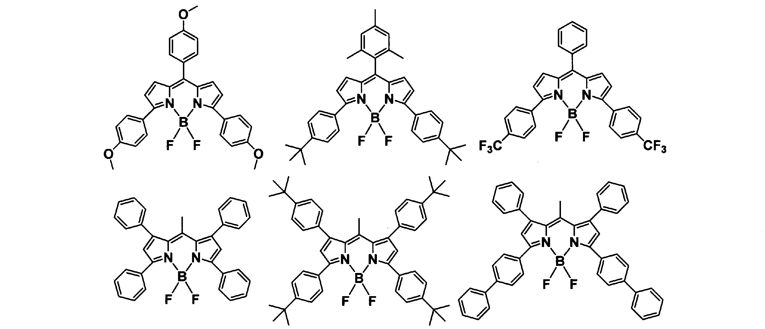

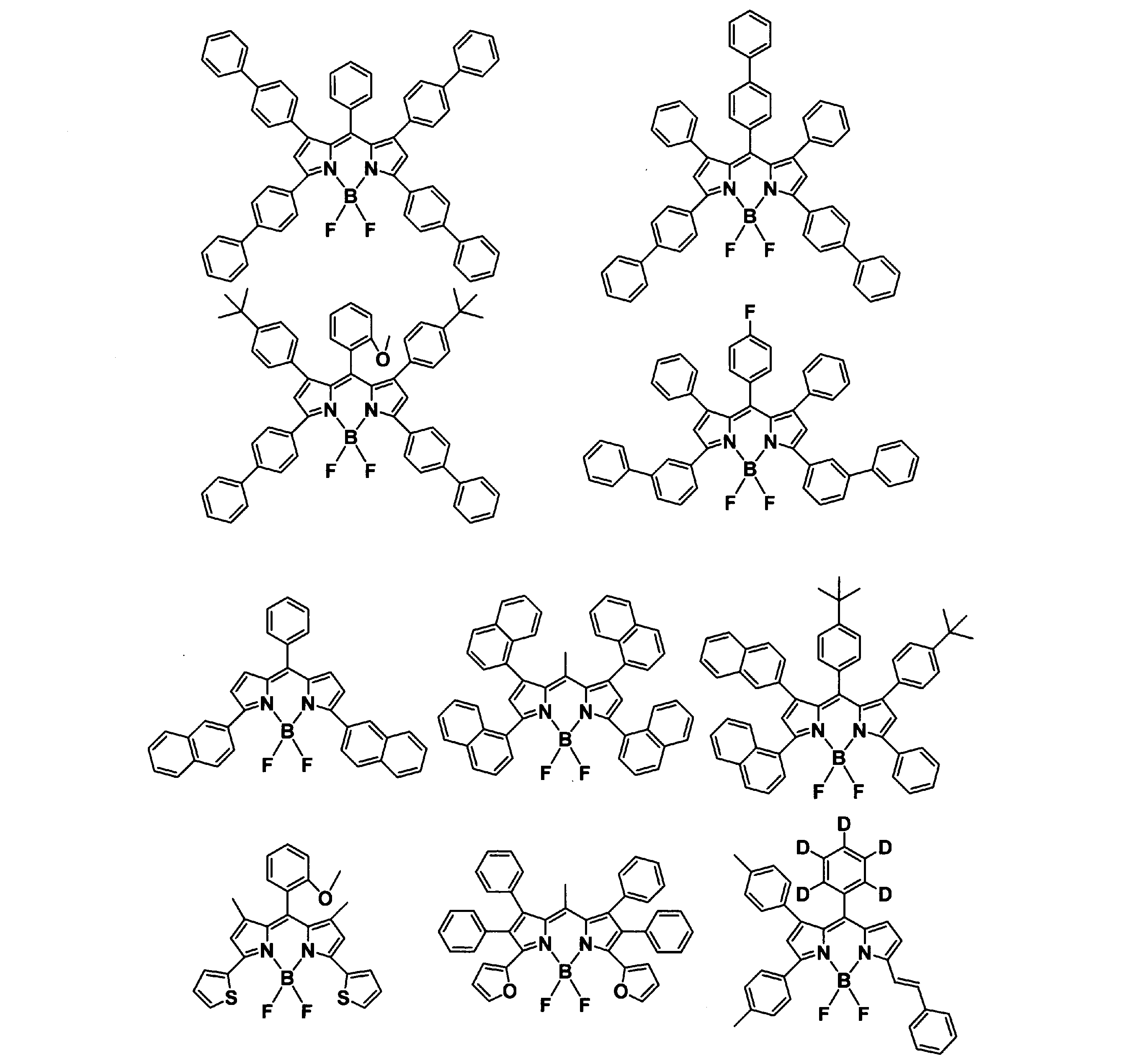
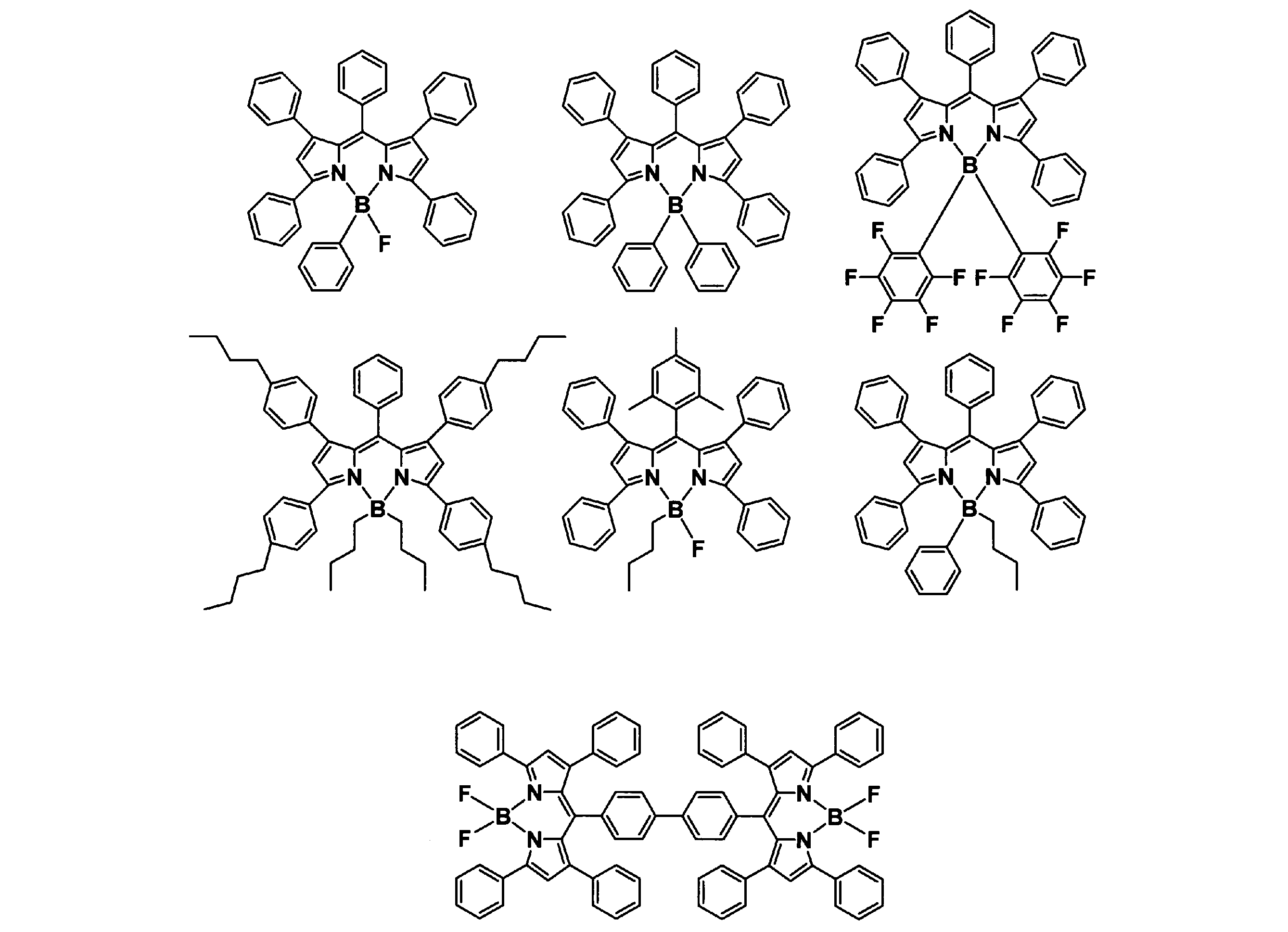
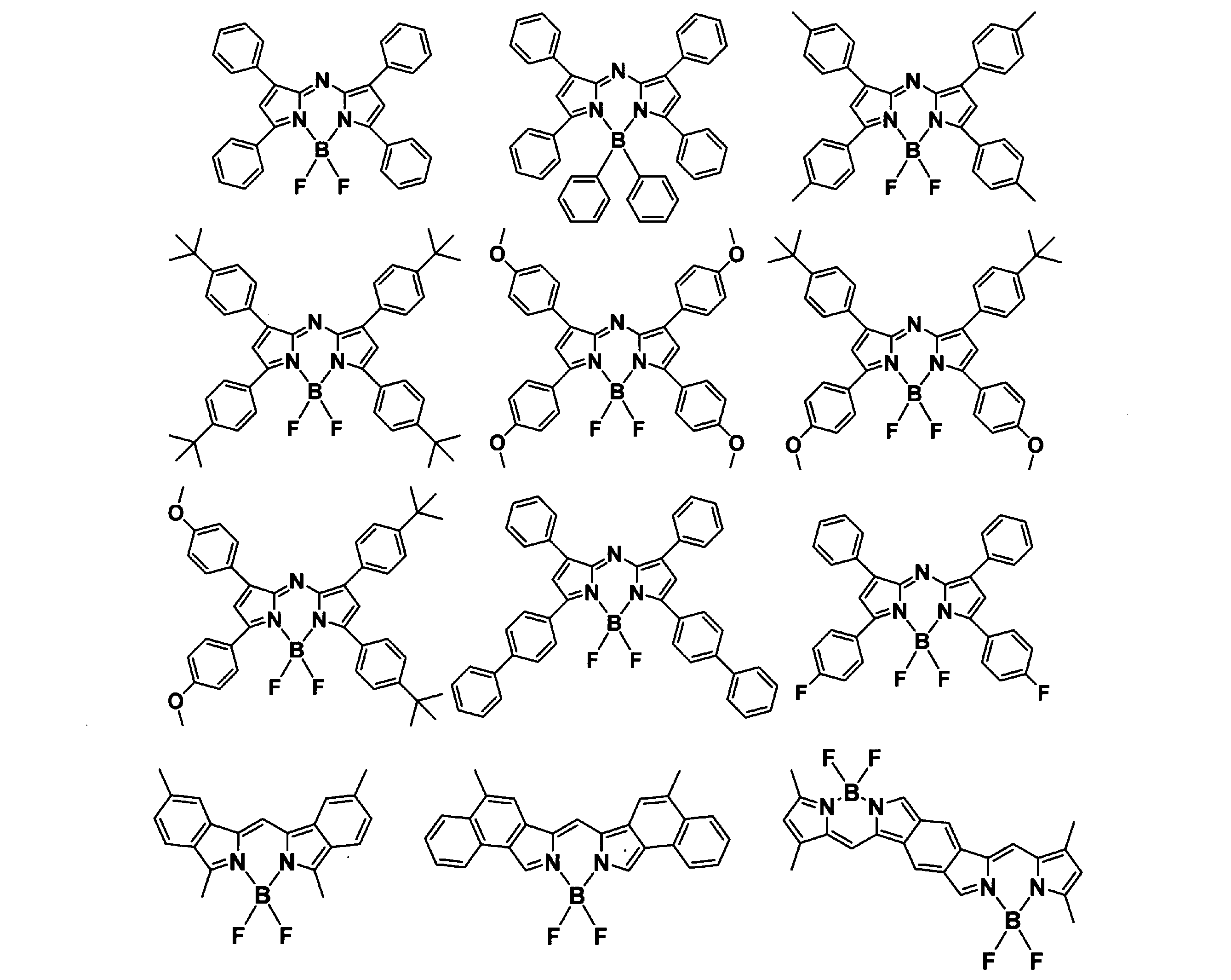
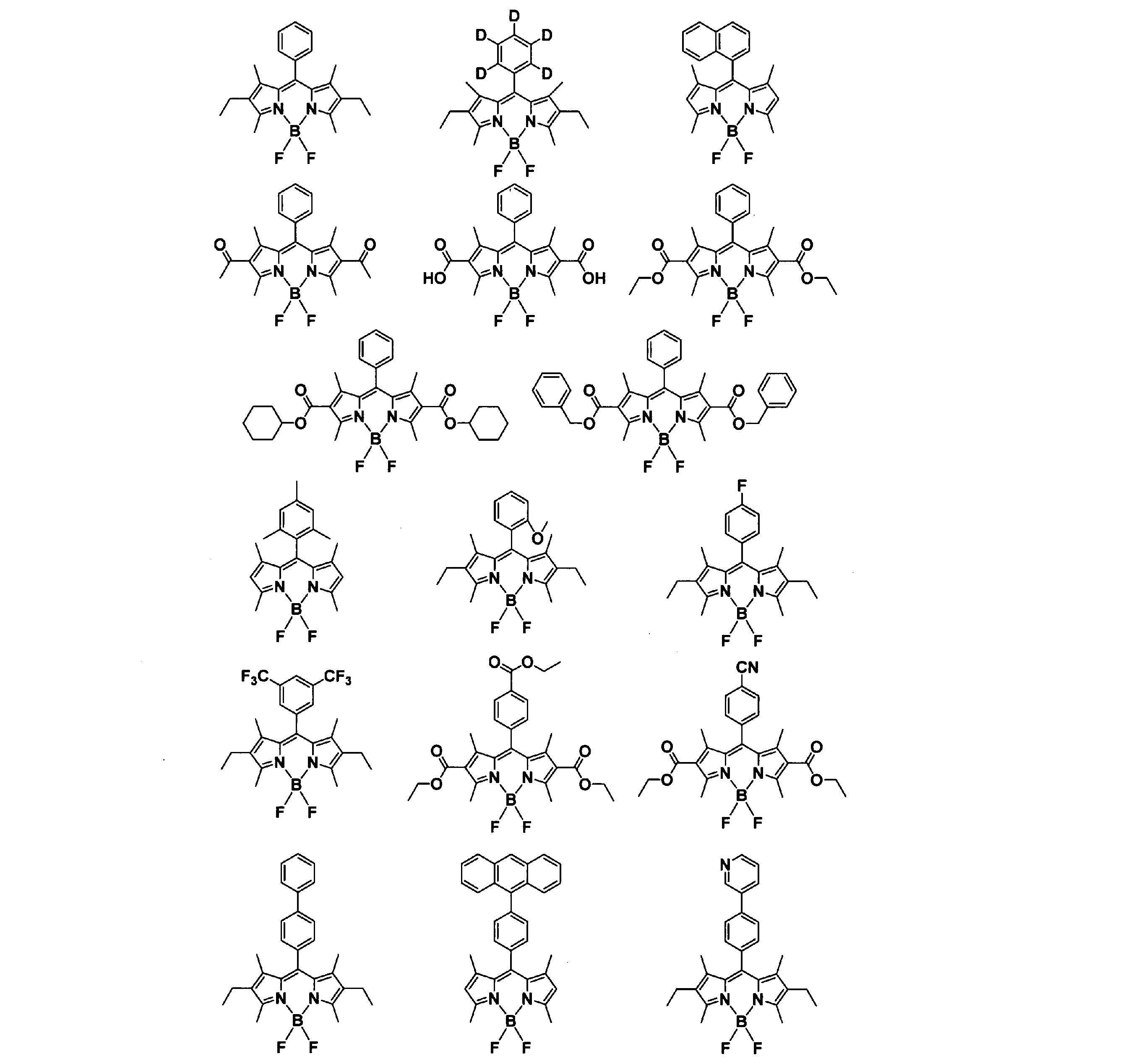

一般式(1)で表される化合物は、例えば特表平8-509471号公報や特開2000-208262号公報に記載の方法により製造することができる。すなわち、ピロメテン化合物と金属塩を塩基共存下で反応させることにより、目的とするピロメテン系金属錯体が得られる。
また、ピロメテン-フッ化ホウ素錯体の合成については、J.Org.Chem.,vol.64,No.21,pp7813-7819(1999),Angew.Chem.,Int.Ed.Engl.,vol.36,pp1333-1335(1997)などに記載されている方法を参考に製造することができる。例えば、下記一般式(3)で表される化合物と一般式(4)で表される化合物を、オキシ塩化リン存在下、1,2-ジクロロエタン中で加熱した後、下記一般式(5)で表される化合物を、トリエチルアミン存在下、1,2-ジクロロエタン中で反応させる方法が挙げられるが、これに限定されるものではない。ここで、R1~R9は前記と同様である。Jはハロゲンを表す。

さらに、アリール基やヘテロアリール基の導入の際は、ハロゲン化誘導体とボロン酸あるいはボロン酸エステル化誘導体とのカップリング反応を用いて炭素-炭素結合を生成する方法が挙げられるが、これに限定されるものではない。同様に、アミノ基やカルバゾリル基の導入の際にも、例えば、パラジウムなどの金属触媒下でのハロゲン化誘導体とアミンあるいはカルバゾール誘導体とのカップリング反応を用いて炭素-窒素結合を生成する方法が挙げられるが、これに限定されるものではない。
本発明の色変換層は、励起光から遅延蛍光を放出する化合物へのエネルギー移動効率を高めるために、ルブレンなどのアシストドーパントを含有してもよい。
一般式(1)で表される化合物以外の有機発光材料の一例を以下に示すが、特にこれらに限定されるものではない。
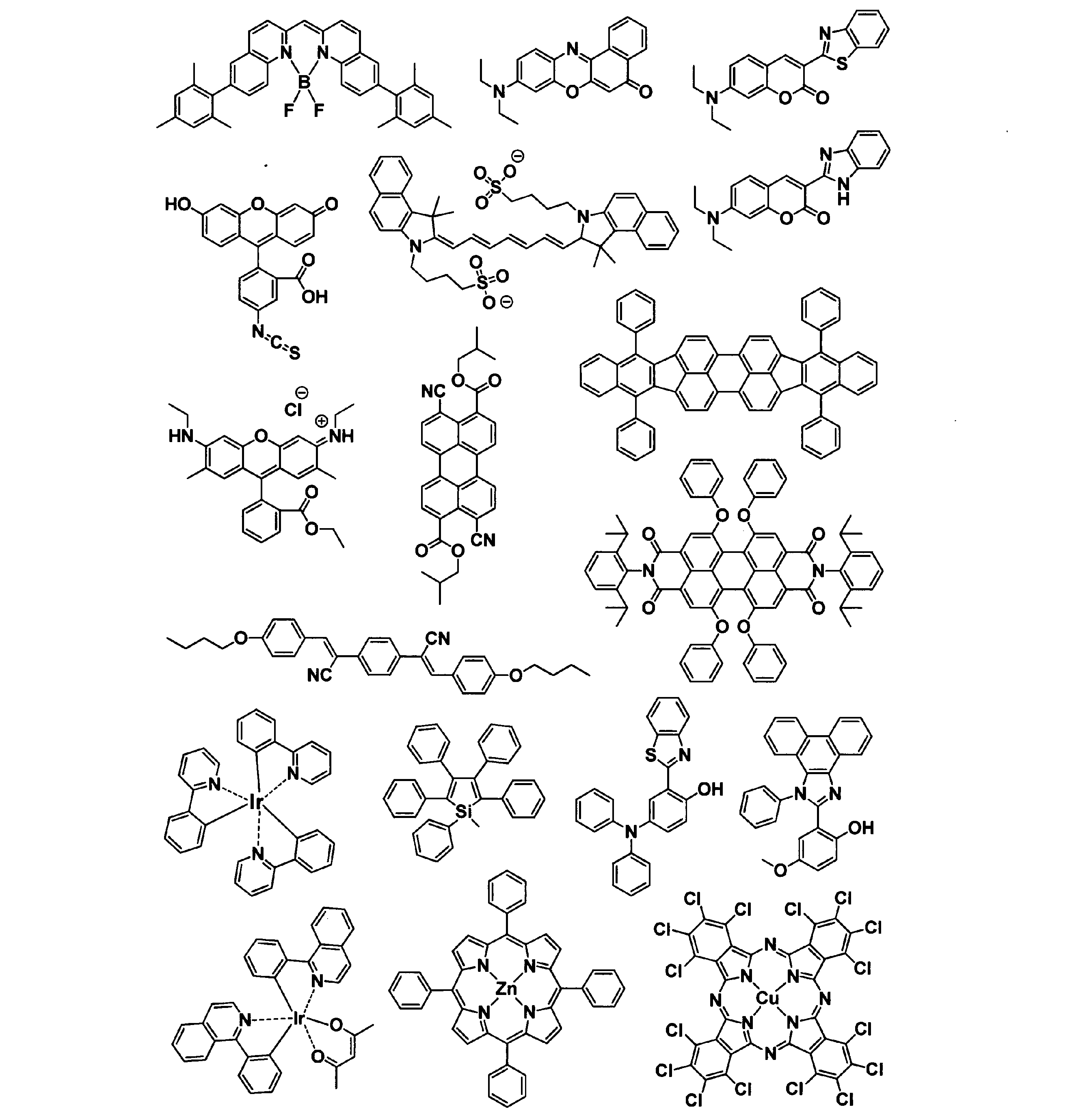
無機蛍光体としては、例えば、SrAl2O4:Eu、Y2SiO5:Ce,Tb、MgAl11O19:Ce,Tb、Sr7Al12O25:Eu、MgGa2S4:Eu、CaGa2S4:Eu、SrGa2S4:Eu、BaGa2S4:Euなどの緑色蛍光体や;Sr5(PO4)3Cl:Eu、(SrCaBa)5(PO4)3Cl:Eu、(BaCa)5(PO4)3Cl:Eu、B5O9Cl:Eu,Mn、Mg(PO4)6Cl2:Eu,Mn、Ca(PO4)6Cl2:Eu,Mn、Sr(PO4)6Cl2:Eu,Mn、Ba(PO4)6Cl2:Eu,Mnなどの青色蛍光体や;例えば、Y2O2S:Eu、La2O2S:Eu、Y2O3:Eu、Gd2O2S:Eu、K2SiF6:Mnなどの赤色蛍光体がある。その他にもY3(Al,Ga)5O12:Ce,(Y,Gd)3Al5O12:Ce,Lu3Al5O12:Ce,Y3Al5O12:CeなどのYAG系蛍光体、Tb3Al5O12:CeなどのTAG系蛍光体、(Ba,Sr)2SiO4:Eu系蛍光体やCa3Sc2Si3O12:Ce系蛍光体、(Sr,Ba,Mg)2SiO4:Euなどのシリケート系蛍光体、(Ca,Sr)2Si5N8:Eu、(Ca,Sr)AlSiN3:Eu、CaSiAlN3:Eu等のナイトライド系蛍光体、Cax(Si,Al)12(O,N)16:Euなどのオキシナイトライド系蛍光体、さらには(Ba,Sr,Ca)Si2O2N2:Eu系蛍光体、Ca8MgSi4O16Cl2:Eu系蛍光体、SrAl2O4:Eu,Sr4Al14O25:Eu等の蛍光体が挙げられる。
量子ドットは、優れた量子効率を有する蛍光体であり、ナノサイズ(例えば、直径2nm~10nm程度)の半導体結晶中に、電子・正孔や励起子を三次元空間全方位で閉じ込めることで、離散的エネルギー準位を有し、そのドットのサイズを変えることで発光光のピーク波長(発光色)等を自由に選択することができる。量子ドットに用いられる材料としては、2価の陽イオンになり得るZn、Cd、Pb等と、2価の陰イオンになり得るO、S、Se、Te等とを組み合わせた材料(例えば、セレン化カドミウム(CdSe)、硫化亜鉛(ZnS)等)、3価の陽イオンとなり得るGa、In等と3価の陰イオンとなり得るP、As、Sb等とを組み合わせた材料(例えば、リン化インジウム(InP)、ヒ化ガリウム(GaAs)等)、さらにはカルコパイライト型化合物(CuInSe2等)等が挙げられる。量子ドット蛍光体の材料の好ましい一例として、CdSeが挙げられる。
遅延蛍光を放出する化合物については、「最先端の有機EL」(安達千波矢、藤本弘編、シーエムシー出版発行)の87~103ページで解説されている。その文献の中で、発光材料の一重項励起状態と三重項励起状態のエネルギー準位を近接させることにより、通常は遷移確率が低い三重項励起状態から一重項励起状態への逆エネルギー移動が高効率で生じ、熱活性化遅延蛍光(Thermally Activated delayed Fluorescence, TADF)が発現すると説明されている。さらに、当該文献中の図5で、遅延蛍光の発生メカニズムが説明されている。遅延蛍光の発光は過渡PL(Photo Luminescence)測定により確認できる。
本明細書では、熱活性化遅延蛍光を発現する化合物を含め、三重項励起状態から一重項励起状態へ高効率で遷移し蛍光を放出する化合物を、「遅延蛍光を放出する化合物」と表記する。
通常、蛍光発光は発光材料が光励起された後に生成する一重項励起状態から放出され、系間交差により生じた発光材料の三重項励起状態は、室温環境下であれば、熱失活し蛍光は放出されない。一方、上述のように、遅延蛍光を放出する化合物は、三重項励起状態が生成しても、速やかに一重項励起状態に変換されたのち、蛍光を放出するので、通常の蛍光発光材料において発光に寄与することができなかった三重項励起状態も蛍光発光に寄与することができる。したがって、高効率の発光が得られる。
遅延蛍光を放出する化合物の三重項励起状態は速やかに一重項励起状態に変換するため、一重項酸素を発生させにくいという特徴を有している。そして、この特徴により、発光材料の劣化を防ぎ、色度の経時的な変化を抑制して耐久性を向上させられることが見出されたのである。
一重項励起状態のエネルギー準位と三重項励起状態のエネルギー準位を近接させる分子設計としては、同一分子内において、電子ドナー性骨格と電子アクセプター性骨格とを結合させることが有効である。そうすることで、分子内で、HOMO(Highest occupied molecular orbital)軌道とLUMO(Lowest unoccupied molecular orbital)軌道を分離させることができる。電子ドナー性骨格と電子アクセプター性骨格は直接結合していてもよいし、連結基を介して結合していてもよい。この場合の連結基としては、芳香族炭化水素を含む骨格であることが好ましい。
電子ドナー性骨格としては、例えば、アミン窒素原子を有する骨格が挙げられる。中でも、ジアリールアミンやトリアリールアミンを含む骨格、カルバゾールを含む骨格、ベンゾカルバゾールを含む骨格、インドロカルバゾールを含む骨格、フェノキサジンを含む骨格、およびフェノチアジンを含む骨格から選ばれる骨格が好ましい。これらの中でも、カルバゾールを含む骨格、ベンゾカルバゾールを含む骨格、インドロカルバゾールを含む骨格、およびフェノキサジンを含む骨格から選ばれる骨格がより好ましく、カルバゾールを含む骨格、およびフェノキサジンを含む骨格から選ばれる骨格がさらに好ましい。
一方、電子アクセプター性骨格としては、通常、電子求引性を有する置換基を含む骨格が挙げられる。電子求引基とは、電子受容性基とも呼称し、有機電子論において、誘起効果や共鳴効果により、置換した原子団から、電子を引き付ける原子団である。電子求引基としては、ハメット則の置換基定数(σp(パラ))として、正の値をとるものが挙げられる。ハメット則の置換基定数(σp(パラ))は、化学便覧基礎編改訂5版(II-380頁)から引用することができる。
なお、フェニル基も正の値をとる例もあるが、本願の電子求引基にフェニル基は含まれない。
電子求引基の例として、例えば、-F(σp:+0.20)、-Cl(σp:+0.28)、-Br(σp:+0.30)、-I(σp:+0.30)、-CO2R12(σp:R12がエチル基の時+0.45)、-CONH2(σp:+0.38)、-COR12(σp:R12がメチル基の時+0.49)、-CF3(σp:+0.51)、-SO2R12(σp:R12がメチル基の時+0.69)、-NO2(σp:+0.81)等が挙げられる。R12は、水素原子、置換もしくは無置換の環形成炭素数6~30の芳香族炭化水素基、置換もしくは無置換の環形成原子数5~30の複素環基、置換もしくは無置換の炭素数1~30のアルキル基、置換もしくは無置換の炭素数1~30のシクロアルキル基を表す。これら各基の具体例としては、上記と同様の例が挙げられる。
中でも、炭素原子と窒素原子が二重結合で結合した部分構造を有するヘテロアリール基を含む骨格、フッ素化された置換基を含む骨格、シアノ基を含む骨格、カルボニル基を含む骨格、スルホキシドまたはジスルホキシドを含む骨格、およびホスフィンオキシド基を含む骨格等が好ましい。これらの中でも、炭素原子と窒素原子が二重結合で結合した部分構造を有するヘテロアリール基を含む骨格、フッ素化された置換基を含む骨格、およびシアノ基を含む骨格が、化合物の安定性の観点でさらに好ましい。
炭素原子と窒素原子が二重結合で結合した部分構造を有するヘテロアリール基を含む骨格の中では、具体的には、ピリジン、ピリミジン、ピラジン、トリアジン、キノリン、キノキサリン、キナゾリン、またはフェナントロリンを含む骨格が好ましく、中でもピリミジン、トリアジン、キノキサリン、またはキナゾリンを含む骨格がより好ましく、トリアジンを含む骨格がさらに好ましい。
フッ素化された置換基を含む骨格の中では、フッ化アリール基、またはフルオロアルキル基を含む骨格がより好ましい。フッ化アリール基を含む骨格としては、フッ素化されたベンゼン環が好ましく、具体的には、フルオロベンゼン、ジフルオロベンゼン、トリフルオロベンゼン、テトラフルオロベンゼンまたはペンタフルオロベンゼンを含む骨格がより好ましい。フルオロアルキル基を含む骨格としては、トリフルオロメチル基で置換されたベンゼン環を含む骨格が好ましく、これらの中でもモノ(トリフルオロメチル)ベンゼンまたはビス(トリフルオロメチル)ベンゼンを含む骨格であることがより好ましい。
シアノ基を有する骨格の中では、シアノベンゼン、ジシアノベンゼン、トリシアノベンゼンを含む骨格がさらに好ましい。
以上のような電子ドナー性骨格と電子アクセプター性骨格を結合させた化合物として一例を以下に示すが、特にこれらに限定されるものではない。なお、ここに示した化合物は過去の文献により遅延蛍光を放出することが知られている。

また、遅延蛍光を放出する化合物として、上述した電子ドナー性骨格と電子アクセプター性骨格を結合させた化合物以外に、一般式(6)または(7)で表される化合物が好ましい。

一般式(6)または(7)において、環Za、環Zbおよび環Zcは、それぞれ独立に、置換もしくは無置換の環形成炭素数6~30のアリール環、または置換もしくは無置換の環形成炭素数6~30ヘテロアリール環である。
Z1およびZ2は、それぞれ独立に、酸素原子、NRa(置換基Raを有する窒素原子)または硫黄原子である。Z1がNRaである場合、Raは環Zaもしくは環Zbと結合して環を形成してもよい。Z2がNRaである場合、Raは環Zaもしくは環Zcと結合して環を形成してもよい。
Eは、ホウ素原子、リン原子、SiRa(置換基Raを有するケイ素原子)またはP=Oである。E1およびE2は、それぞれ独立に、BRa(置換基Raを有するホウ素原子)、PRa(置換基Raを有するリン原子)、SiRa2(置換基Raを2個有するケイ素原子)、P(=O)Ra2(置換基Raを2個有するホスフィンオキシド)、P(=S)Ra2(置換基Raを2個有するホスフィンスルフィド)、S(=O)またはS(=O)2である。E1がBRa、PRa、SiRa2、P(=O)Ra2またはP(=S)Ra2である場合、Raは環Zaもしくは環Zbと結合して環を形成してもよい。E2がBRa、PRa、SiRa2、P(=O)Ra2またはP(=S)Ra2である場合、Raは環Zaもしくは環Zcと結合して環を形成してもよい。Raは、それぞれ独立に、置換もしくは無置換のアリール基、置換もしくは無置換のヘテロアリール基、または置換もしくは無置換のアルキル基である。
環Za、環Zbおよび環Zcにおける置換もしくは無置換の環形成炭素数6~30のアリール環としては、ベンゼン環、ナフタレン環、フェナントレン環、クリセン環、アントラセン環、ピレン環といった芳香族炭化水素環が挙げられる。これらの中でも溶解性を確保する観点でベンゼン環が好ましい。また環形成炭素数5~30のヘテロアリール環としてはピリジン環、キノリン環、フェナントロリン環といった芳香族ヘテロアリール環構造が挙げられる。原料入手のしやすさや合成の難易度の観点ではピリジン環が好ましい。
Raは、置換基も含めて炭素数6~40の基であることが好ましい。Raは、置換もしくは無置換のアリール基であることがより好ましい。置換もしくは無置換のアリール基としては、置換もしくは無置換のフェニル基、置換もしくは無置換のビフェニル基、置換もしくは無置換のフルオレニル基、置換もしくは無置換のナフチル基、置換もしくは無置換のフェナントレニル基等が挙げられる。置換もしくは無置換のフェニル基がより好ましい。
Rbは、置換基も含めて炭素数6~40基であることが好ましい。Rbは、置換もしくは無置換のアリール基または置換もしくは無置換のアルキル基であることがより好ましい。
Z1およびZ2は酸素原子またはNRaであることが好ましい。一般式(6)または(7)で表される化合物のπ共役系が効率よく拡張し、より効率的に三重項励起状態から一重項励起状態に逆項間交差が起きるため、耐久性をさらに向上することができるからである。
Eはホウ素原子であることが好ましく、E1およびE2はBRaであることが好ましい。一般式(6)または(7)で表される化合物のπ共役系が効率よく拡張し、より効率的に三重項励起状態から一重項励起状態に逆項間交差が起きるため、耐久性をさらに向上することができるからである。
環Za、環Zbおよび環Zcはベンゼン環であることが好ましい。一般式(7)または(7)で表される化合物のπ共役系が効率よく拡張し、より効率的に三重項励起状態から一重項励起状態に逆項間交差が起きるため、耐久性をさらに向上することができるからである。
一般式(6)または(7)で表される化合物は、例えば文献Adv.Mater.,2016,28,2777-2781 に記載されているように、電子ドナー性のアミン窒素原子と電子アクセプター性のホウ素原子を最適に配置することで、多重共鳴効果によりHOMO軌道とLUMO軌道を分離させることが可能な分子である。HOMO軌道とLUMO軌道を明瞭に分離し、一重項励起状態と三重項励起状態をより近接させ遅延蛍光を放出しやすくするという観点では、Eが電子アクセプター性の強いホウ素原子であり、かつZ1とZ2がどちらも電子ドナー性の強い基であるNRaであることが好ましい。
また一般式(6)または(7)で表される化合物は、多重共鳴効果により、その発光スペクトルが、電子ドナー性骨格と電子アクセプター性骨格を結合させた化合物よりもシャープとなり、高色純度の発光が得られる。すなわち、一般式(6)または(7)で表される化合物はディスプレイの色域向上に有利であるため、好ましい。また、一般式(6)または(7)で表される化合物は、主にLUMO軌道が局在する一般式(6)または(7)中のE原子の周囲に環Za、環Zb、環Zcが存在することから、LUMO軌道をE原子から各環にわたって非局在化することができる。LUMO軌道を非局在化することで効率的に多重共鳴効果が働くため、より高色純度の発光が得られる。
さらに、一般式(6)または(7)のRaが、環Za、環Zb、および環Zcの少なくとも一つの環と結合した構造がより好ましい。これは、Raが環Za、環Zb、および環Zcの少なくとも一つの環と結合することにより、一般式(6)中のEや一般式(7)中のE1およびE2の立体保護効果がより高まり、蛍光量子収率の低下を抑える効果がより向上することが期待できるためである。
以下に一般式(6)または(7)で表される化合物の一例を以下に示すが、特にこれらに限定されるものではない。

(散乱粒子)
色変換シートは、効率的および均一に色変換を達成させる観点から、散乱粒子を含むことが好ましい。散乱粒子は、色変換層に含まれることがより好ましい。散乱粒子としては、有機物および/または無機物の粒子が挙げられる。
色変換シートは、効率的および均一に色変換を達成させる観点から、散乱粒子を含むことが好ましい。散乱粒子は、色変換層に含まれることがより好ましい。散乱粒子としては、有機物および/または無機物の粒子が挙げられる。
具体的には、ガラス、チタニア、シリカ、アルミナ、シリコーン樹脂、ジルコニア、セリア、窒化アルミ、炭化ケイ素、窒化ケイ素、チタン酸バリウム、アクリル樹脂などで構成される粒子が挙げられる。これらは単独で用いられてもよく、2種類以上併用されてもよい。入手しやすいという観点から、シリカ粒子、アルミナ粒子、チタニア粒子、ジルコニア粒子、アクリル樹脂粒子、シリコーン樹脂粒子などから選ばれる粒子が好ましい。色変換層中のバインダー樹脂への分散性の観点からは、チタニア粒子がより好ましい。また輝度向上の観点からは、散乱粒子がアルミナ粒子、シリカ粒子およびシリコーン樹脂粒子から選ばれた粒子を含むことが好ましい。
散乱粒子の平均粒径は、特に限定はないが、100nm~5000nmが好ましく、さらには100nm~500nmであることが好ましい。平均粒径がこの範囲の散乱粒子を使用することによってバインダー樹脂への分散性が良好となり、発光材料の光散乱効率が向上する。
散乱粒子の含有量は、特に限定はないが、0.03g/m2~2.1g/m2が好ましく、さらには0.9g/m2~2.1g/m2が好ましく、0.9g/m2~1.4g/m2がより好ましい。散乱粒子の含有量がこの範囲であることにより、色変換層中の反射率を効率よく上げることができ、かつ輝度との両立を可能とする。散乱粒子の含有量[g/m2]は、色変換層1m2中の散乱粒子の含有量を意味する。色変換シートが色変換層(A)および色変換層(B)を含む場合、いずれか一方の層または両方の層において、散乱粒子の含有量が上記の範囲であることが好ましい。
また本発明において、色変換シートが色変換層(A)および色変換層(B)を含む場合においては、色変換層(A)および色変換層(B)の少なくとも一方が散乱粒子を含有することが好ましい。散乱粒子は色変換層(A)および色変換層(B)のいずれかに偏った状態で含まれることが好ましい。ここで、散乱粒子が偏った状態で含まれるとは、色変換層(A)および色変換層(B)のいずれかのみが散乱粒子を含有するか、もしくは、色変換層(A)および色変換層(B)における散乱粒子の含有量が異なることを意味する。色変換層(A)が散乱粒子を含有する場合、(A)層の発光効率が向上し、ピーク波長が短波長化することにより、より大きな色域の色変換シートが得られる。また、色変換層(B)が散乱粒子を含有する場合、(B)層の色変換効率が向上し、自己吸収が抑制されることでピーク波長が短波長化する。色変換層(B)のピーク波長が短波長化すると、より視感度ピークに近づけることが可能となり、より高輝度な色変換シートを得ることができる。
従って、高色域の観点からは、色変換層(A)における散乱粒子の含有量が色変換層(B)における散乱粒子の含有量よりも大きいことが好ましく、色変換層(A)のみが散乱粒子を含有することが最も好ましい。一方、高輝度の観点からは、色変換層(B)における散乱粒子の含有量が色変換層(A)における散乱粒子の含有量よりも大きいことが好ましく、色変換層(B)のみが散乱粒子を含有することが最も好ましい。
色変換層中に含有する発光材料として、前述したピロメテン誘導体や一般式(6)、(7)で表される化合物を使用した場合、それらの化合物はストークスシフトが小さいことから自己吸収が強くなる傾向にある。そのため、散乱粒子の偏りによる高輝度および高色域に効果が顕著に現れる。
(バインダー樹脂)
色変換層に含まれるバインダー樹脂は、連続相を形成するものであり、成型加工性、透明性、耐熱性等に優れる材料であればよい。バインダー樹脂の例としては、例えば、アクリル酸系、メタクリル酸系、ポリケイ皮酸ビニル系、環ゴム系等の反応性ビニル基を有する光硬化型レジスト材料、エポキシ樹脂、シリコーン樹脂(シリコーンゴム、シリコーンゲル等のオルガノポリシロキサン硬化物(架橋物)を含む)、ウレア樹脂、フッ素樹脂、ポリカーボネート樹脂、アクリル樹脂、ウレタン樹脂、メラミン樹脂、ポリビニル樹脂、ポリアミド樹脂、フェノール樹脂、ポリビニルアルコール樹脂、セルロース樹脂、脂肪族エステル樹脂、芳香族エステル樹脂、脂肪族ポリオレフィン樹脂、芳香族ポリオレフィン樹脂等の公知のものが挙げられる。また、バインダー樹脂としては、これらの共重合樹脂を用いても構わない。これらの樹脂を適宜設計することで、本発明の実施形態に係る色変換組成物および色変換シートに有用なバインダー樹脂が得られる。これらの樹脂の中でも、透明性、耐熱性等の観点から、エポキシ樹脂、シリコーン樹脂、アクリル樹脂、エステル樹脂、オレフィン樹脂またはこれらの混合物を好適に用いることができる。また、耐久性の観点から、アクリル樹脂、エステル樹脂およびシクロオレフィン樹脂から選ばれた樹脂がより好ましい。
色変換層に含まれるバインダー樹脂は、連続相を形成するものであり、成型加工性、透明性、耐熱性等に優れる材料であればよい。バインダー樹脂の例としては、例えば、アクリル酸系、メタクリル酸系、ポリケイ皮酸ビニル系、環ゴム系等の反応性ビニル基を有する光硬化型レジスト材料、エポキシ樹脂、シリコーン樹脂(シリコーンゴム、シリコーンゲル等のオルガノポリシロキサン硬化物(架橋物)を含む)、ウレア樹脂、フッ素樹脂、ポリカーボネート樹脂、アクリル樹脂、ウレタン樹脂、メラミン樹脂、ポリビニル樹脂、ポリアミド樹脂、フェノール樹脂、ポリビニルアルコール樹脂、セルロース樹脂、脂肪族エステル樹脂、芳香族エステル樹脂、脂肪族ポリオレフィン樹脂、芳香族ポリオレフィン樹脂等の公知のものが挙げられる。また、バインダー樹脂としては、これらの共重合樹脂を用いても構わない。これらの樹脂を適宜設計することで、本発明の実施形態に係る色変換組成物および色変換シートに有用なバインダー樹脂が得られる。これらの樹脂の中でも、透明性、耐熱性等の観点から、エポキシ樹脂、シリコーン樹脂、アクリル樹脂、エステル樹脂、オレフィン樹脂またはこれらの混合物を好適に用いることができる。また、耐久性の観点から、アクリル樹脂、エステル樹脂およびシクロオレフィン樹脂から選ばれた樹脂がより好ましい。
バインダー樹脂の好適な具体例として、例えば、国際公開第2016/190283号、国際公開第2017/61337号、国際公開第2018/43237号、国際公開第2019/21813号および国際公開第2019/188019号等に記載されているものが挙げられる。
また、バインダー樹脂には、添加剤として、塗布膜安定化のための分散剤やレベリング剤等を添加することも、シート表面の改質剤として、シランカップリング剤等の接着補助剤等を添加することも可能である。また、バインダー樹脂には、色変換材沈降抑制剤として、シリカ粒子やシリコーン微粒子等の無機粒子を添加することも可能である。
(その他添加剤)
色変換層は、バインダー樹脂、発光材料以外に、充填剤、酸化防止剤、加工および熱安定化剤、紫外線吸収剤等の耐光性安定化剤、塗布膜安定化のための分散剤やレベリング剤、可塑剤、エポキシ化合物などの架橋剤、アミン・酸無水物・イミダゾールなどの硬化剤、顔料、シート表面の改質剤としてシランカップリング剤等の接着補助剤等を添加することも可能である。
色変換層は、バインダー樹脂、発光材料以外に、充填剤、酸化防止剤、加工および熱安定化剤、紫外線吸収剤等の耐光性安定化剤、塗布膜安定化のための分散剤やレベリング剤、可塑剤、エポキシ化合物などの架橋剤、アミン・酸無水物・イミダゾールなどの硬化剤、顔料、シート表面の改質剤としてシランカップリング剤等の接着補助剤等を添加することも可能である。
充填剤としてはフュームドシリカ、ガラス粉末、石英粉末等の微粒子、酸化チタン、酸化ジルコニア、チタン酸バリウム、酸化亜鉛、シリコーン微粒子などを挙げることができるが特に限定されるものではない。また、これらの充填剤は単独で使用してもよく、複数併用してもよい。
酸化防止剤としては、2,6-ジ-tert-ブチル-p-クレゾール、2,6-ジ-tert-ブチル-4-エチルフェノール等のフェノール系酸化防止剤を挙げることができるが特に限定されるものではない。また、これらの酸化防止剤は単独で使用してもよく、複数併用してもよい。
加工および熱安定化剤としては、トリブチルホスファイト、トリシクロヘキシルホスファイト、トリエチルホスフィン、ジフェニルブチルホスフィン等のリン系安定化剤を挙げることができるが特に限定されるものではない。また、これらの安定化剤は単独で使用してもよく、複数併用してもよい。
耐光性安定化剤としては、例えば、2-(5-メチル-2-ヒドロキシフェニル)ベンゾトリアゾール、2-〔2-ヒドロキシ-3,5-ビス(α,α-ジメチルベンジル)フェニル〕-2H-ベンゾトリアゾール等のベンゾトリアゾール類を挙げることができるが特に限定されるものではない。また、これらの耐光性安定化剤は単独で使用してもよく、複数併用してもよい。
色変換層におけるこれらの添加剤の含有量は、化合物のモル吸光係数、蛍光量子収率および励起波長における吸収強度、ならびに作製するシートの厚みや透過率にもよるが、通常はバインダー樹脂100質量部に対して、1.0×10⁻³質量部以上30質量部以下が好ましく、1.0×10⁻²質量部以上15質量部以下であることがさらに好ましく、1.0×10⁻¹質量部以上10質量部以下であることが特に好ましい。
(溶媒)
色変換層は溶媒を含んでいてもよい。溶媒は、流動状態の樹脂の粘度を調整でき、発光材料の発光および耐久性に過度な影響を与えないものであれば、特に限定されない。溶媒としては、例えば、水、2-プロパノール、エタノール、トルエン、メチルエチルケトン、メチルイソブチルケトン、シクロペンタノン、シクロヘキサノン、ヘキサン、ヘプタン、アセトン、酢酸メチル、酢酸エチル、酢酸ブチル、酢酸プロピル、酢酸イソプロピル、テルピネオール、テキサノール、メチルセルソルブ、エチルセルソルブ、ブチルカルビトール、ブチルカルビトールアセテート、1-メトキシ-2-プロパノール、プロピレングリコールモノメチルエーテルアセテート、テトラヒドロフラン、テトラヒドロピラン、1,4-ジオキサン等が挙げられる。これらの溶媒を2種類以上混合して使用することも可能である。これらの溶媒の中で特にトルエンおよび酢酸エチルから選ばれる溶媒は、一般式(1)で表される化合物の劣化に影響を与えず、乾燥後の残存溶媒が少ない点で好適に用いられる。
色変換層は溶媒を含んでいてもよい。溶媒は、流動状態の樹脂の粘度を調整でき、発光材料の発光および耐久性に過度な影響を与えないものであれば、特に限定されない。溶媒としては、例えば、水、2-プロパノール、エタノール、トルエン、メチルエチルケトン、メチルイソブチルケトン、シクロペンタノン、シクロヘキサノン、ヘキサン、ヘプタン、アセトン、酢酸メチル、酢酸エチル、酢酸ブチル、酢酸プロピル、酢酸イソプロピル、テルピネオール、テキサノール、メチルセルソルブ、エチルセルソルブ、ブチルカルビトール、ブチルカルビトールアセテート、1-メトキシ-2-プロパノール、プロピレングリコールモノメチルエーテルアセテート、テトラヒドロフラン、テトラヒドロピラン、1,4-ジオキサン等が挙げられる。これらの溶媒を2種類以上混合して使用することも可能である。これらの溶媒の中で特にトルエンおよび酢酸エチルから選ばれる溶媒は、一般式(1)で表される化合物の劣化に影響を与えず、乾燥後の残存溶媒が少ない点で好適に用いられる。
(バリア層)
本発明の実施の形態に係る色変換シートは、バリア層をさらに備えていてもよい。バリア層は、酸素、水分や熱による色変換層の劣化を防ぐために適宜用いることができる。バリア層は、色変換層に接するように設けることが好ましい。バリア層は、色変換層の両面に設けてもよいし、片面だけに設けてもよい。
本発明の実施の形態に係る色変換シートは、バリア層をさらに備えていてもよい。バリア層は、酸素、水分や熱による色変換層の劣化を防ぐために適宜用いることができる。バリア層は、色変換層に接するように設けることが好ましい。バリア層は、色変換層の両面に設けてもよいし、片面だけに設けてもよい。
バリア層としては、具体的には、酸化ケイ素、酸化アルミニウム、酸化チタン、酸化タンタル、酸化亜鉛、酸化スズ、酸化インジウム、酸化イットリウム、酸化マグネシウムなどの無機酸化物や、窒化ケイ素、窒化アルミニウム、窒化チタン、炭化窒化ケイ素などの無機窒化物、またはこれらの混合物、またはこれらに他の元素を添加した金属酸化物薄膜や金属窒化物薄膜、あるいはポリ塩化ビニリデン、アクリル系樹脂、シリコーン系樹脂、メラミン系樹脂、ウレタン系樹脂、フッ素系樹脂、酢酸ビニルのけん化物等のポリビニルアルコール系樹脂などの各種樹脂からなる膜を挙げることができる。また、水分に対してバリア機能を有する膜としては、例えば、ポリエチレン、ポリプロピレン、ナイロン、ポリ塩化ビニリデン、塩化ビニリデンと塩化ビニル、塩化ビニリデンとアクリロニトリルの共重合物、フッ素系樹脂、酢酸ビニルのけん化物等のポリビニルアルコール系樹脂などの各種樹脂からなる膜を挙げることができる。
(その他の層)
また、本発明の実施の形態に係る色変換シートは、色変換シートに要求される機能に応じて、光取り出し機能、反射防止機能、防眩機能、反射防止防眩機能、ハードコート機能(耐摩擦機能)、帯電防止機能、防汚機能、電磁波シールド機能、赤外線カット機能、紫外線カット機能、偏光機能、調色機能等の機能を有した補助層をさらに備えてもよい。また、粘着層を、複数の色変換層の間に設けてもよい。
また、本発明の実施の形態に係る色変換シートは、色変換シートに要求される機能に応じて、光取り出し機能、反射防止機能、防眩機能、反射防止防眩機能、ハードコート機能(耐摩擦機能)、帯電防止機能、防汚機能、電磁波シールド機能、赤外線カット機能、紫外線カット機能、偏光機能、調色機能等の機能を有した補助層をさらに備えてもよい。また、粘着層を、複数の色変換層の間に設けてもよい。
色変換シートの厚みは特に制限はないが、全ての層の合計で1~5000μmであることが好ましい。厚みが1μm以上であることで十分な膜強度を担保することができ、膜の破断等の問題が発生しにくくなる。厚みが5000μm以下であることによりハンドリング性に優れたシートを得ることができる。厚みは、より好ましくは、10~1000μmであり、さらに好ましくは15~500μmであり、特に好ましくは30~300μmである。
本発明における色変換シートに関する膜厚は、JIS K7130(1999)プラスチック-フィルムおよびシート-厚さ測定方法における機械的走査による厚さの測定方法A法に基づいて測定される膜厚(平均膜厚)のことをいう。
<色変換シートの作製方法>
以下に、本発明の実施の形態に係る色変換シートの作製方法の一例を説明する。この色変換シートの作製方法では、まず、色変換層作製用の組成物を以下のように作製する。前述した発光材料、バインダー樹脂、溶媒等を所定量混合する。上記の成分を所定の組成になるよう混合した後、ホモジナイザー、自公転型攪拌機、3本ローラー、ボールミル、遊星式ボールミル、ビーズミル等の撹拌・混練機で均質に混合分散することで、色変換組成物が得られる。混合分散後、もしくは混合分散の過程で、真空もしくは減圧条件下で脱泡することも好ましく行われる。また、ある特定の成分を事前に混合することや、エージング等の処理をしても構わない。エバポレーターによって溶媒を除去して所望の固形分濃度にすることも可能である。
以下に、本発明の実施の形態に係る色変換シートの作製方法の一例を説明する。この色変換シートの作製方法では、まず、色変換層作製用の組成物を以下のように作製する。前述した発光材料、バインダー樹脂、溶媒等を所定量混合する。上記の成分を所定の組成になるよう混合した後、ホモジナイザー、自公転型攪拌機、3本ローラー、ボールミル、遊星式ボールミル、ビーズミル等の撹拌・混練機で均質に混合分散することで、色変換組成物が得られる。混合分散後、もしくは混合分散の過程で、真空もしくは減圧条件下で脱泡することも好ましく行われる。また、ある特定の成分を事前に混合することや、エージング等の処理をしても構わない。エバポレーターによって溶媒を除去して所望の固形分濃度にすることも可能である。
次に、上述した方法で作製した色変換組成物を基材上に塗布し、乾燥させる。ここでいう基材は、上述した基材層と光抽出層とが一体となった基材フィルムであることが好ましい。塗布は、リバースロールコーター、ブレードコーター、スリットダイコーター、ダイレクトグラビアコーター、オフセットグラビアコーター、キスコーター、ナチュラルロールコーター、エアーナイフコーター、ロールブレードコーター、トゥーストリームコーター、ロッドコーター、ワイヤーバーコーター、アプリケーター、ディップコーター、カーテンコーター、スピンコーター、ナイフコーター等を用いて行うことができる。色変換層の膜厚均一性を得るためにはスリットダイコーターまたはディップコーターで塗布することが好ましい。
色変換層の乾燥は熱風乾燥機や赤外線乾燥機等の一般的な加熱装置を用いて行うことができる。この場合、加熱条件は、通常、40~250℃で1分~5時間が好ましく、より好ましくは60℃~200℃で2分~4時間である。また、ステップキュア等を用いて段階的に加熱硬化することも可能である。
色変換層を作製した後、必要に応じて基材を取り替えることも可能である。この場合、簡易的な方法としてはホットプレートを用いて貼り替えを行なう方法や、真空ラミネーターやドライフィルムラミネーターを用いた方法などが挙げられるが、これらに限定されない。
<光源ユニット>
本発明の実施の形態に係る光源ユニットは、少なくとも光源および色変換シートを含むものである。本発明における光源ユニットに含まれる光源の種類は、発光材料が吸収可能な波長領域に発光を示すものであればいずれも用いることができる。例えば、熱陰極管や冷陰極管、無機ELなどの蛍光性光源、有機エレクトロルミネッセンス素子、発光ダイオード(LED)、白熱光源などいずれの光源でも原理的には利用可能であるが、中でもLEDが好適な光源である。ディスプレイや照明装置に用いる光源ユニットにおいては、青色光の色純度を高められる点で、波長400~500nmの範囲に極大発光を有する青色LEDが好適な光源である。波長400~500nmの範囲の励起光は比較的小さい励起エネルギーであり、発光材料の分解を防止できる点でも好ましい。励起光は1種類の発光ピークを持つものでもよく、2種類以上の発光ピークを持つものでもよいが、色純度を高めるためには1種類の発光ピークを持つものが好ましい。また、発光ピークの種類の異なる複数の励起光源を任意に組み合わせて使用することも可能である。
本発明の実施の形態に係る光源ユニットは、少なくとも光源および色変換シートを含むものである。本発明における光源ユニットに含まれる光源の種類は、発光材料が吸収可能な波長領域に発光を示すものであればいずれも用いることができる。例えば、熱陰極管や冷陰極管、無機ELなどの蛍光性光源、有機エレクトロルミネッセンス素子、発光ダイオード(LED)、白熱光源などいずれの光源でも原理的には利用可能であるが、中でもLEDが好適な光源である。ディスプレイや照明装置に用いる光源ユニットにおいては、青色光の色純度を高められる点で、波長400~500nmの範囲に極大発光を有する青色LEDが好適な光源である。波長400~500nmの範囲の励起光は比較的小さい励起エネルギーであり、発光材料の分解を防止できる点でも好ましい。励起光は1種類の発光ピークを持つものでもよく、2種類以上の発光ピークを持つものでもよいが、色純度を高めるためには1種類の発光ピークを持つものが好ましい。また、発光ピークの種類の異なる複数の励起光源を任意に組み合わせて使用することも可能である。
青色光源と本発明の色変換シートを組み合わせることにより、青色光源から白色光を得ることが可能となり、白色光を発光する光源ユニットとして用いることができる。
光源と色変換シートとの配置方法については特に限定しないが、色変換シートにおいて光抽出層が光源側とは反対の面に配置されてなることが好ましい。また、光源側に色変換シートの第2の面を対向させるように色変換シートが配置されてなることが好ましく、これにより光源からの青色光をより多く反射することができるので、色の角度依存性が小さくなる。
色変換シートが色変換層(A)および色変換層(B)を含む場合には、色変換層(B)が色変換層(A)よりも光源側に配置されることが好ましい。
光源ユニットには、光源および色変換シート以外に、他の光学シートを含んでもよい。他の光学シートとしては、プリズムシート、偏光反射性フィルム、拡散シートなどが挙げられる。代表的な構成の例としては、図6に示すように、基板7、反射層8、光源9を積層させ、拡散板10とプリズムシート11との間に本発明の実施の形態に係る色変換シート5を配置し、さらにプリズムシート11の光源とは反対側の面に偏光反射性フィルム12を配置する構成がある。その他の構成として、光源と色変換シートとを密着させた構成を取ってもよいし、光源と色変換シートとを離したリモートフォスファー形式を取ってもよい。また、光源ユニットは、色純度を高める目的で、さらにカラーフィルターを備える構成を取ってもよい。
本発明の光源ユニットは、ディスプレイのバックライトユニット、照明装置、インテリア、標識、看板、などの用途に使用できる。特にディスプレイや照明装置に好適に用いられる。
<ディスプレイ、照明装置>
本発明の実施の形態に係るディスプレイおよび照明装置は、少なくとも上述の光源ユニットを備える。
本発明の実施の形態に係るディスプレイおよび照明装置は、少なくとも上述の光源ユニットを備える。
ディスプレイとしては、例えば、有機ELディスプレイや液晶ディスプレイなどが挙げられる。有機ELディスプレイの構成の一例としては、波長400~500nmの範囲に極大発光を有する青色に発光するEL素子を光源として、その上に本発明のシートを配置して白色光を発光する光源ユニットとし、カラーフィルターと組み合わせてフルカラー表示とする構成が挙げられる。液晶ディスプレイの構成の一例としては、バックライトユニットとして、上述の光源ユニットを使用し、さらにカラーフィルターを備える液晶セル、偏光フィルム、輝度向上フィルムなどの光学フィルムを含む構成が挙げられる。
照明装置としては、本発明の光源ユニットをそのまま照明装置として用いてもよいし、本発明の光源ユニットに加え、拡散板やヒートシンクをさらに含んでいてもよいし、色温度を調整するためのカラーフィルターをさらに含んでいてもよい。
以下、実施例をあげて本発明を説明するが、本発明はこれらの例によって限定されるものではない。
<表面粗さRaの測定>
光抽出層の表面粗さRaはサーフコム1400G(株式会社 東京精密製)を用いてJIS B 0601(2013)に準拠し測定した。測定回数はそれぞれ1回ずつとした。
光抽出層の表面粗さRaはサーフコム1400G(株式会社 東京精密製)を用いてJIS B 0601(2013)に準拠し測定した。測定回数はそれぞれ1回ずつとした。
<全反射率の測定>
実施例および比較例で作製した色変換シートの全反射率は分光測色計CM-2600D(コニカミノルタ株式会社製)を用いてASTM E1164に準拠し、SCI(Specular Component Include)を測定した。測定波長440~470nmの波長領域における全反射率の平均値および520~580nmの波長領域における全反射率の平均値をそれぞれ算出した。測定回数はそれぞれ1回ずつとした。
実施例および比較例で作製した色変換シートの全反射率は分光測色計CM-2600D(コニカミノルタ株式会社製)を用いてASTM E1164に準拠し、SCI(Specular Component Include)を測定した。測定波長440~470nmの波長領域における全反射率の平均値および520~580nmの波長領域における全反射率の平均値をそれぞれ算出した。測定回数はそれぞれ1回ずつとした。
<色の角度依存性評価>
BenQ社製液晶モニター(SW2700PT)を分解し、内蔵されていた色変換シートの代わりに後述の実施例および比較例で作製した色変換シートを挿入した後、元通り組み立てた。この時のバックライトユニットの構成は「反射フィルム/導光板/色変換シート/拡散シート/プリズムシート/偏光反射フィルム」である。得られたモニターで青、緑、赤の単色を表示したときの(x、y)色空間におけるそれぞれの色座標を分光放射輝度計(CS-1000、コニカミノルタ社製)を用いて測定した。分光放射輝度計は、モニターの中心点に対して直角に配置し、モニターをそのまま直角配置して測定したときのx、yとモニターを垂直方向に30度傾けて測定したときのx、yの差をそれぞれΔx、Δyとして算出した。モニターと分光放射輝度計との測定距離は50cmとした。Δx、Δyが0.015以下であれば、色の角度依存性が小さい、良好な色変換シートであり、0.01以下であればより良好であり、0.005以下であれば極めて良好である。
BenQ社製液晶モニター(SW2700PT)を分解し、内蔵されていた色変換シートの代わりに後述の実施例および比較例で作製した色変換シートを挿入した後、元通り組み立てた。この時のバックライトユニットの構成は「反射フィルム/導光板/色変換シート/拡散シート/プリズムシート/偏光反射フィルム」である。得られたモニターで青、緑、赤の単色を表示したときの(x、y)色空間におけるそれぞれの色座標を分光放射輝度計(CS-1000、コニカミノルタ社製)を用いて測定した。分光放射輝度計は、モニターの中心点に対して直角に配置し、モニターをそのまま直角配置して測定したときのx、yとモニターを垂直方向に30度傾けて測定したときのx、yの差をそれぞれΔx、Δyとして算出した。モニターと分光放射輝度計との測定距離は50cmとした。Δx、Δyが0.015以下であれば、色の角度依存性が小さい、良好な色変換シートであり、0.01以下であればより良好であり、0.005以下であれば極めて良好である。
<相対輝度>
色の角度依存性評価と同様にBenQ社製液晶モニター(SW2700PT)を分解し、内蔵されていた色変換シートの代わりに後述の実施例および比較例で作製した色変換シートを挿入した後、元通り組み立て、分光放射輝度計(CS-1000、コニカミノルタ社製)を用いて輝度を測定した。実施例1の色変換後の白色光の輝度を100として、後述の実施例および比較例の輝度を比較した。相対輝度(%)は実施例1を基準とする相対的な輝度である。
色の角度依存性評価と同様にBenQ社製液晶モニター(SW2700PT)を分解し、内蔵されていた色変換シートの代わりに後述の実施例および比較例で作製した色変換シートを挿入した後、元通り組み立て、分光放射輝度計(CS-1000、コニカミノルタ社製)を用いて輝度を測定した。実施例1の色変換後の白色光の輝度を100として、後述の実施例および比較例の輝度を比較した。相対輝度(%)は実施例1を基準とする相対的な輝度である。
<発光材料>
下記実施例および比較例において、化合物G-1およびR-1は以下に示す化合物である。
下記実施例および比較例において、化合物G-1およびR-1は以下に示す化合物である。
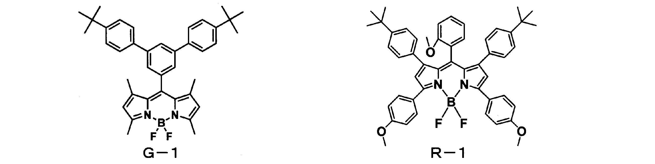
化合物G-1(発光ピーク波長:515nm)は公知の方法により合成した。
化合物R-1(発光ピーク波長:629.5nm)は公知の方法により合成した。
化合物R-1(発光ピーク波長:629.5nm)は公知の方法により合成した。
<基材フィルム>
基材フィルムA:“ルミラー”(登録商標)U48(東レ株式会社製、厚さ100μm)を用いた。
基材フィルムA:“ルミラー”(登録商標)U48(東レ株式会社製、厚さ100μm)を用いた。
基材フィルムB:樹脂としてLUXYDIR(登録商標) V-4221(ウレタンアクリレート、DIC株式会社製)を100重量部、微粒子としてMX-80H3WT(架橋アクリル単分散粒子、平均粒径0.8μm、綜研化学株式会社製)を0.15重量部、溶媒としてトルエンを25重量部混合した後、遊星式撹拌・脱泡装置“マゼルスター”(登録商標)KK-400(クラボウ(株)製)を用い、1000rpmで20分間撹拌・脱泡して光抽出層作製用組成物を得た。
次にスリットダイコーターを用いて光抽出層作製用組成物を、基材層である“ルミラー”(登録商標)U48(東レ(株)製、厚さ100μm)上に塗布し、80℃で20分加熱することにより塗膜を乾燥させた。その後、高圧水銀ランプにて積算光量250mJ/cm2の紫外線を照射して光抽出層作製用組成物を硬化させて平均膜厚1μmの光抽出層を形成し、基材フィルムBを得た。
基材フィルムC:微粒子をMX-300(架橋アクリル単分散粒子、平均粒径3μm、綜研化学(株)製)に変更したこと以外は、基材フィルムBと同様の操作にて基材フィルムCを得た。
基材フィルムD:微粒子をMX-500L(架橋アクリル単分散粒子、平均粒径5μm、綜研化学(株)製)に変更したこと以外は、基材フィルムBと同様の操作にて基材フィルムDを得た。
基材フィルムE:微粒子をMX-1000(架橋アクリル単分散粒子、平均粒径10μm、綜研化学(株)製)に変更した以外は、基材フィルムBと同様の操作にて基材フィルムEを得た。
(実施例1)
樹脂としてオリコックス(登録商標)KC-7000(アクリル樹脂、共栄社化学(株)製)を100重量部、発光材料としてG-1を0.2重量部、R-1を0.02重量部、散乱粒子としてJR-405(チタニア粒子、平均粒径0.21μm、テイカ(株)製)を3.3重量部、および溶媒としてトルエンを300重量部混合した後、遊星式撹拌・脱泡装置“マゼルスター”(登録商標)KK-400(クラボウ(株)製)を用い、1000rpmで20分間撹拌・脱泡して色変換層作成用樹脂組成物を得た。
樹脂としてオリコックス(登録商標)KC-7000(アクリル樹脂、共栄社化学(株)製)を100重量部、発光材料としてG-1を0.2重量部、R-1を0.02重量部、散乱粒子としてJR-405(チタニア粒子、平均粒径0.21μm、テイカ(株)製)を3.3重量部、および溶媒としてトルエンを300重量部混合した後、遊星式撹拌・脱泡装置“マゼルスター”(登録商標)KK-400(クラボウ(株)製)を用い、1000rpmで20分間撹拌・脱泡して色変換層作成用樹脂組成物を得た。
同様に樹脂として“クラリティ”(登録商標)LA2140(アクリル樹脂、(株)クラレ製)を用いて樹脂100重量部に対して、溶媒としてトルエンを160重量部混合した後、遊星式撹拌・脱泡装置“マゼルスター”(登録商標)KK-400(クラボウ(株)製)を用い、300rpmで20分間撹拌・脱泡して粘着層用樹脂組成物を得た。
次に、スリットダイコーターを用いて色変換層作成用樹脂組成物を、基材フィルムCの光抽出層とは反対の面に塗布し、120℃で20分加熱、乾燥して平均膜厚25μmの色変換層を形成した。
次に、スリットダイコーターを用いて粘着層用樹脂組成物を、上記とは別の基材フィルムCの光抽出層とは反対の面に塗布し、120℃で20分間加熱・乾燥して平均膜厚10μmの粘着層を形成した。
次に、上記2つのユニットを、色変換層と粘着層が直接積層するように加温ラミネートすることにより、「光抽出層/基材層/色変換層/粘着層/基材層/光抽出層」という構成の色変換シートを作製した。
作製した色変換シートを用いて前述の方法にて両方の面それぞれの全反射率、色の角度依存性および輝度を測定した。結果を表1に示す。任意の面を光源側に配置する面、反対側の面を視認側に配置する面として測定したが、本実施例の色変換シートは対照的な構造を有するので表1に示す通り、いずれの面から測定した値も同じになっている。
(実施例2~6、比較例1~4)
基材フィルムの種類および色変換層中の散乱粒子の添加量を表1に示すように変更した以外は、実施例1と同様の操作にて色変換シートを作製し、評価した。結果を表1に示す。
基材フィルムの種類および色変換層中の散乱粒子の添加量を表1に示すように変更した以外は、実施例1と同様の操作にて色変換シートを作製し、評価した。結果を表1に示す。
実施例1と比較例1の対比から、440nm~470nmの波長領域での全反射率の平均値が10%よりも低い比較例1と比べ、上記全反射率の平均値が10%以上である実施例1は大幅に色の角度依存性が小さくなった。
また、実施例1~4の対比から、上記全反射率の平均値が大きいほど色の角度依存性が小さくなることが分かった。ただし、比較例2で示すように、上記全反射率の平均値が60%を超えると、色の角度依存性が小さくなるものの、輝度が大幅に低下することが分かった。実施例1、2は色の角度依存性と輝度のバランスの点で特に良好であった。
実施例1と比較例3の対比から、光抽出層の表面粗さが0.05μmよりも小さい比較例3と比べ、表面粗さが0.05μm以上である実施例1は大幅に輝度が良好となった。
また、実施例1、5、6および比較例4の対比から、光抽出層の表面粗さが0.05μm~2μmの範囲であると、輝度は良好であることが分かった。
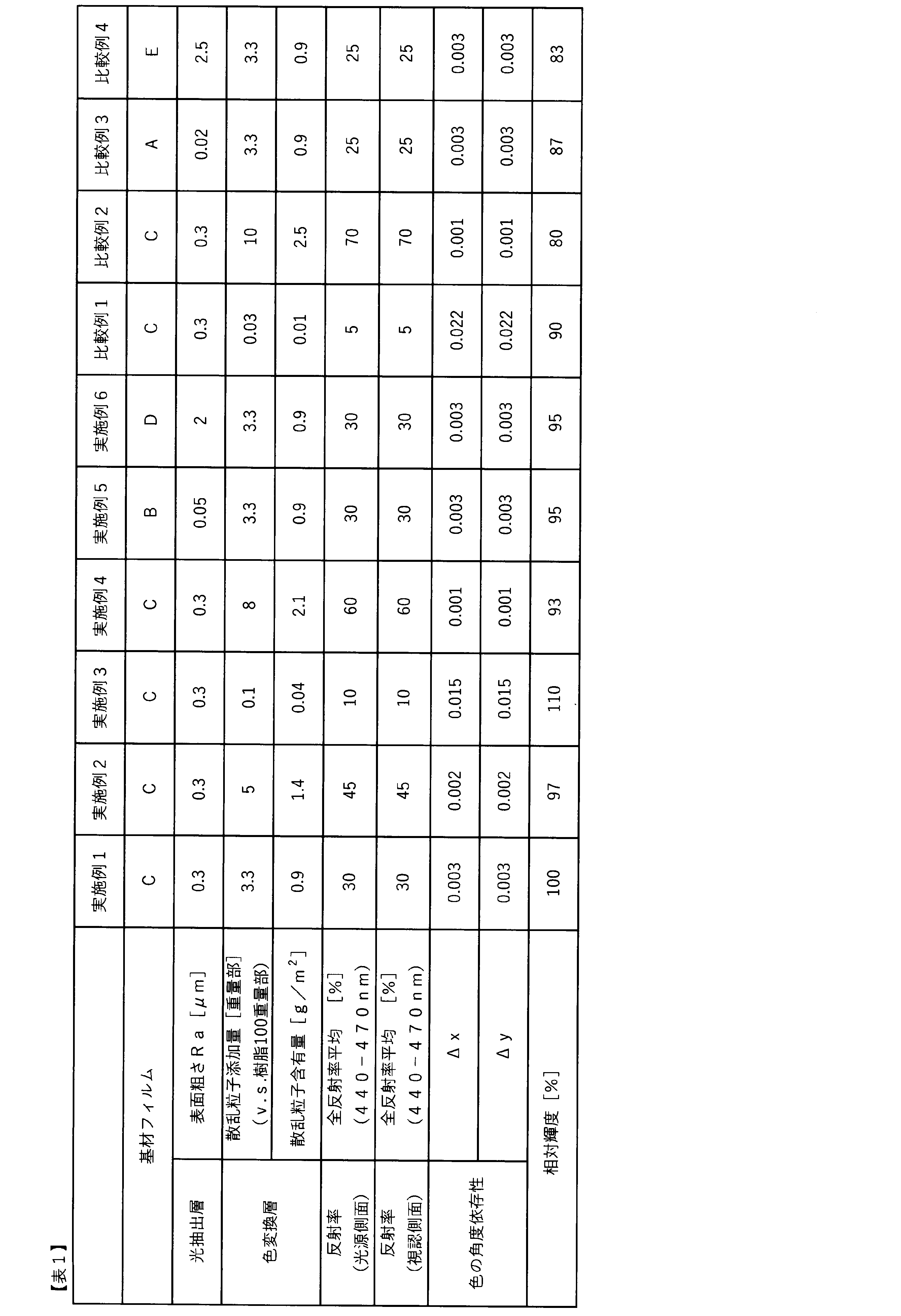
(実施例7)
R-1を添加しなかった以外は実施例1と同様の操作にて色変換層作製用樹脂組成物(A)を得た。
R-1を添加しなかった以外は実施例1と同様の操作にて色変換層作製用樹脂組成物(A)を得た。
G-1を添加しなかった以外は実施例1と同様の操作にて色変換層作製用樹脂組成物(B)を得た。
実施例1と同様の操作にて粘着層用樹脂組成物を得た。
次に、スリットダイコーターを用いて色変換層作成用樹脂組成物(A)を、基材フィルムCの光抽出層とは反対の面に塗布し、120℃で20分加熱、乾燥して平均膜厚25μmの色変換層(A)を形成した。
次に、スリットダイコーターを用いて色変換層作成用樹脂組成物(B)を、上記とは別の基材フィルムCの光抽出層とは反対の面に塗布し、120℃で20分加熱、乾燥して平均膜厚25μmの色変換層(B)を形成した。
同様にスリットダイコーターを用いて色変換層(B)上に粘着作成用樹脂組成物を塗布し、120℃で20分加熱、乾燥して平均膜厚10μmの粘着層を形成した。
次に、上記2つのユニットを、色変換層(A)と粘着層が直接積層するように加温ラミネートすることにより、「光抽出層/基材層/色変換層(A)/粘着層/色変換層(B)/基材層/光抽出層」という構成の色変換シートを作製した。
作製した色変換シートを用いて、前述の方法にて両方の面それぞれの全反射率を測定した。色変換層(A)側の面の方が色変換層(B)側の面よりも520nm~580nmの波長領域における全反射率の平均値が大きいので、色変換層(A)側の面が第1の面、色変換層(B)側の面が第2の面となる。前述の方法にて色の角度依存性および輝度を測定した。Rb1およびRg1は色変換層(A)側の面(第1の面)から測定した全反射率の平均値であり、Rb2およびRg2は色変換層(B)側の面(第2の面)から測定した全反射率の平均値である。なお色の角度依存性および輝度の測定は、色変換シートの色変換層(B)側が光源側になるように配置して測定した。
(実施例8~11、比較例5~6)
散乱粒子の添加量を表2に示すように変更した以外は、実施例7と同様の操作にて色変換シートを作製し、評価した。結果を表2に示す。
散乱粒子の添加量を表2に示すように変更した以外は、実施例7と同様の操作にて色変換シートを作製し、評価した。結果を表2に示す。
実施例7、9、10の対比から、Rb2-Rb1が大きいほど色の角度依存性が小さくなることが分かった。
実施例7と実施例11の対比より、散乱粒子が色変換層(B)にのみにある方が、輝度が向上することが分かった。

(実施例12)
実施例7と同様の操作にて色変換シートを作製し、色変換層(B)側の面(第2の面)が視認側になるように測定配置を変更した以外は、実施例7と同様の操作にて評価した。結果を表3に示す。
実施例7と同様の操作にて色変換シートを作製し、色変換層(B)側の面(第2の面)が視認側になるように測定配置を変更した以外は、実施例7と同様の操作にて評価した。結果を表3に示す。
実施例7と実施例12の対比から、色変換層(B)(第2の面)を視認側に配置した実施例12と比べ、光源側に配置した実施例7は色の角度依存性が小さくなることが分かった。
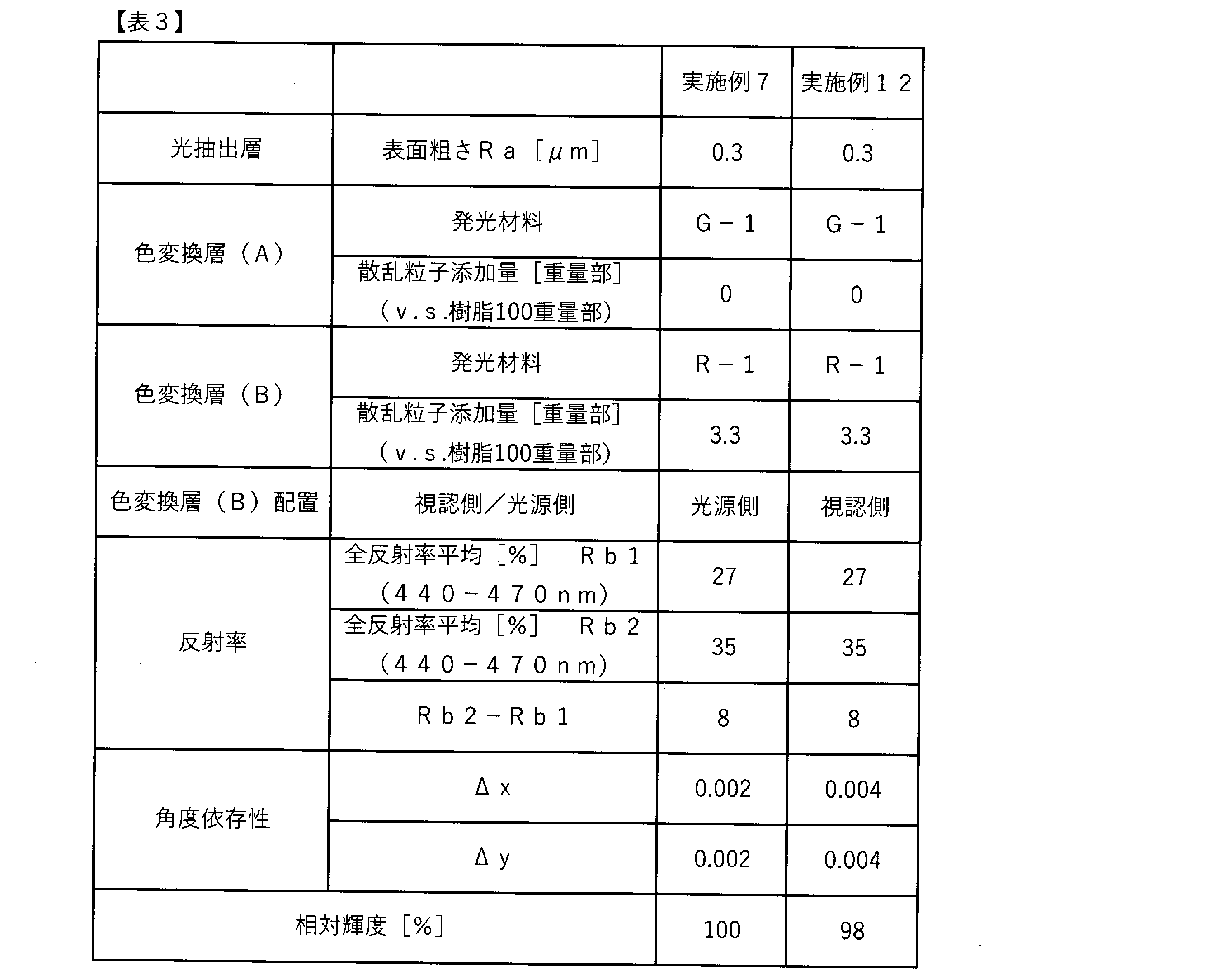
1、1A、1B 光抽出層
2、2A、2B 基材層
3 色変換層
3A 色変換層(A)
3B 色変換層(B)
5、5A、5B、5C、5D、5E 色変換シート
6A、6B バリア層
7 基板
8 反射層
9 光源
10 拡散板
11 プリズムシート
12 偏光反射性フィルム
13 光源ユニット
2、2A、2B 基材層
3 色変換層
3A 色変換層(A)
3B 色変換層(B)
5、5A、5B、5C、5D、5E 色変換シート
6A、6B バリア層
7 基板
8 反射層
9 光源
10 拡散板
11 プリズムシート
12 偏光反射性フィルム
13 光源ユニット
Claims (18)
- 入射光を、その入射光とは異なる波長の光に変換する色変換シートであって、前記色変換シートがその最外層として光抽出層を有し、前記光抽出層の表面粗さRaが0.05μm~2μmであり、前記色変換シートの少なくとも一方の面における440nm~470nmの波長領域での全反射率の平均値が10%~60%である、色変換シート。
- 前記色変換シートの第1の面における520nm~580nmの波長領域での全反射率の平均値をRg1、第2の面における520nm~580nmの波長領域での全反射率の平均値をRg2としたとき、3%≦Rg1-Rg2である、請求項1に記載の色変換シート。
- 前記色変換シートの第1の面における440nm~470nmの波長領域での全反射率の平均値をRb1、第2の面における440nm~470nmの波長領域での全反射率の平均値をRb2としたとき、5%≦Rb2-Rb1≦13%である、請求項1に記載の色変換シート。
- 前記色変換シートの440nm~470nmの波長領域での全反射率の平均値が30%~60%である、請求項1に記載の色変換シート。
- 前記色変換シートの440nm~470nmの波長領域での全反射率の平均値が30%~45%である、請求項1に記載の色変換シート。
- 前記色変換シートが散乱粒子を含有する、請求項1に記載の色変換シート。
- 前記散乱粒子の含有量が0.03g/m2~2.1g/m2である請求項6に記載の色変換シート。
- 前記散乱粒子がチタニア粒子を含む請求項6に記載の色変換シート。
- 前記色変換シートが少なくとも色変換層(A)および色変換層(B)を含み、前記色変換層(A)はピーク波長が500nm以上580nm未満の領域に観測される発光を呈する発光材料(a)を含有し、前記色変換層(B)はピーク波長が580nm以上750nm以下の領域に観測される発光を呈する発光材料(b)を含有する、請求項1に記載の色変換シート。
- 前記発光材料(a)および/または発光材料(b)が有機発光材料である、請求項9に記載の色変換シート。
- 前記有機発光材料(a)および/または発光材料(b)が一般式(1)で表される化合物を含有する、請求項9に記載の色変換シート:

- 前記色変換層(A)および色変換層(B)の少なくとも一方が散乱粒子を含有する、請求項9に記載の色変換シート。
- 光源および請求項1に記載の色変換シートを含む、光源ユニット。
- 前記色変換シートの光抽出層が前記光源側とは反対の面になるように配置されてなる、請求項13に記載の光源ユニット。
- 光源および請求項3に記載の色変換シートを含む光源ユニットであって、前記光源側に前記色変換シートの第2の面を対向させるように前記色変換シートが配置されてなる、光源ユニット。
- 前記光源が400nm以上500nm以下の範囲に極大発光を有する発光ダイオードである、請求項13に記載の光源ユニット。
- 請求項13~16のいずれかに記載の光源ユニットを備える、ディスプレイ。
- 請求項13~16のいずれかに記載の光源ユニットを備える、照明装置。
Priority Applications (2)
| Application Number | Priority Date | Filing Date | Title |
|---|---|---|---|
| CN202480033149.1A CN121152990A (zh) | 2023-06-26 | 2024-06-13 | 颜色转换片以及包含其的光源单元、显示器及照明装置 |
| JP2024537902A JPWO2025004819A1 (ja) | 2023-06-26 | 2024-06-13 |
Applications Claiming Priority (2)
| Application Number | Priority Date | Filing Date | Title |
|---|---|---|---|
| JP2023-104073 | 2023-06-26 | ||
| JP2023104073 | 2023-06-26 |
Publications (1)
| Publication Number | Publication Date |
|---|---|
| WO2025004819A1 true WO2025004819A1 (ja) | 2025-01-02 |
Family
ID=93938839
Family Applications (1)
| Application Number | Title | Priority Date | Filing Date |
|---|---|---|---|
| PCT/JP2024/021454 Ceased WO2025004819A1 (ja) | 2023-06-26 | 2024-06-13 | 色変換シートならびにそれを含む光源ユニット、ディスプレイおよび照明装置 |
Country Status (3)
| Country | Link |
|---|---|
| JP (1) | JPWO2025004819A1 (ja) |
| CN (1) | CN121152990A (ja) |
| WO (1) | WO2025004819A1 (ja) |
Citations (6)
| Publication number | Priority date | Publication date | Assignee | Title |
|---|---|---|---|---|
| JPH09297204A (ja) * | 1996-03-08 | 1997-11-18 | Matsushita Electric Ind Co Ltd | 異方性散乱素子及びそれを用いる液晶ディスプレイ |
| JP2001281426A (ja) * | 2000-03-31 | 2001-10-10 | Kobe Steel Ltd | 紫外線反射板 |
| JP2010097908A (ja) * | 2008-10-20 | 2010-04-30 | Fujifilm Corp | バックライトユニットおよび液晶表示装置 |
| JP2010226095A (ja) * | 2009-02-24 | 2010-10-07 | Hitachi Chem Co Ltd | 配線基板、電子部品パッケージ及びこれらの製造方法 |
| JP2014237267A (ja) * | 2013-06-07 | 2014-12-18 | 古河電気工業株式会社 | 発泡シート、光反射板、バックライトパネル、及び発泡シートを作製するための樹脂シート、並びに発泡シートの製造方法 |
| JP2021099415A (ja) * | 2019-12-20 | 2021-07-01 | 日本特殊陶業株式会社 | 波長変換部材および発光装置 |
-
2024
- 2024-06-13 CN CN202480033149.1A patent/CN121152990A/zh active Pending
- 2024-06-13 WO PCT/JP2024/021454 patent/WO2025004819A1/ja not_active Ceased
- 2024-06-13 JP JP2024537902A patent/JPWO2025004819A1/ja active Pending
Patent Citations (6)
| Publication number | Priority date | Publication date | Assignee | Title |
|---|---|---|---|---|
| JPH09297204A (ja) * | 1996-03-08 | 1997-11-18 | Matsushita Electric Ind Co Ltd | 異方性散乱素子及びそれを用いる液晶ディスプレイ |
| JP2001281426A (ja) * | 2000-03-31 | 2001-10-10 | Kobe Steel Ltd | 紫外線反射板 |
| JP2010097908A (ja) * | 2008-10-20 | 2010-04-30 | Fujifilm Corp | バックライトユニットおよび液晶表示装置 |
| JP2010226095A (ja) * | 2009-02-24 | 2010-10-07 | Hitachi Chem Co Ltd | 配線基板、電子部品パッケージ及びこれらの製造方法 |
| JP2014237267A (ja) * | 2013-06-07 | 2014-12-18 | 古河電気工業株式会社 | 発泡シート、光反射板、バックライトパネル、及び発泡シートを作製するための樹脂シート、並びに発泡シートの製造方法 |
| JP2021099415A (ja) * | 2019-12-20 | 2021-07-01 | 日本特殊陶業株式会社 | 波長変換部材および発光装置 |
Also Published As
| Publication number | Publication date |
|---|---|
| CN121152990A (zh) | 2025-12-16 |
| JPWO2025004819A1 (ja) | 2025-01-02 |
Similar Documents
| Publication | Publication Date | Title |
|---|---|---|
| KR102035515B1 (ko) | 색변환 시트, 그것을 포함하는 광원 유닛, 디스플레이 및 조명 장치 | |
| TWI765048B (zh) | 顏色轉換片、含有其的光源單元、顯示器和照明裝置 | |
| JP7290047B2 (ja) | 色変換組成物、色変換シートならびにそれを含む光源ユニット、ディスプレイおよび照明装置 | |
| JP7559769B2 (ja) | 色変換シートならびにそれを含む光源ユニット、ディスプレイおよび照明装置 | |
| JP7380216B2 (ja) | 色変換部材、光源ユニット、ディスプレイ、照明装置、色変換基板およびインク | |
| JP2019219512A (ja) | 色変換組成物、色変換シートならびにそれを含む光源ユニット、ディスプレイおよび照明装置 | |
| JP7771558B2 (ja) | 色変換シートを含む光源ユニット、ならびにそれを含むディスプレイおよび照明装置 | |
| JP2021076790A (ja) | 色変換フィルム、それを含む光源ユニット、ディスプレイおよび照明 | |
| WO2023008318A1 (ja) | 色変換シート、それを含む光源ユニット、ディスプレイおよび照明装置 | |
| WO2022255173A1 (ja) | 色変換組成物、色変換シート、それを含む光源ユニット、ディスプレイおよび照明装置 | |
| WO2023042751A1 (ja) | 色変換部材、それを含む光源ユニット、ディスプレイおよび照明装置 | |
| CN121152990A (zh) | 颜色转换片以及包含其的光源单元、显示器及照明装置 | |
| WO2024057867A1 (ja) | 色変換組成物、色変換シート、光源ユニット、表示装置および照明装置 | |
| WO2024024590A1 (ja) | 粒子状色変換材料、色変換部材ならびにそれを含む光源ユニット、ディスプレイ、照明装置および色変換基板 | |
| WO2026004747A1 (ja) | 色変換組成物、色変換部材ならびにそれを含む光源ユニット、ディスプレイおよび照明装置 | |
| JP2026005609A (ja) | 色変換組成物、色変換部材ならびにそれを含む光源ユニット、ディスプレイおよび照明装置 | |
| JP2025138053A (ja) | 色変換組成物、色変換部材ならびにそれを含む光源ユニット、ディスプレイおよび照明装置 | |
| WO2022230643A1 (ja) | 多環芳香族化合物、色変換組成物、色変換シート、光源ユニット、ディスプレイおよび照明装置 | |
| JP2026005605A (ja) | 色変換組成物、硬化物、色変換部材ならびにそれを含む光源ユニット、ディスプレイおよび照明装置 | |
| CN117651890A (zh) | 颜色转换片、包括其的光源单元、显示器及照明装置 | |
| JP2023061532A (ja) | 色変換組成物、色変換シート、光源ユニット、ディスプレイおよび照明装置 | |
| CN116874513A (zh) | 一种含硼杂环化合物及其应用 |
Legal Events
| Date | Code | Title | Description |
|---|---|---|---|
| WWE | Wipo information: entry into national phase |
Ref document number: 2024537902 Country of ref document: JP |
|
| 121 | Ep: the epo has been informed by wipo that ep was designated in this application |
Ref document number: 24831684 Country of ref document: EP Kind code of ref document: A1 |
|
| NENP | Non-entry into the national phase |
Ref country code: DE |
|
| 122 | Ep: pct application non-entry in european phase |
Ref document number: 24831684 Country of ref document: EP Kind code of ref document: A1 |