WO2025004791A1 - 分析装置、及び、分析方法 - Google Patents
分析装置、及び、分析方法 Download PDFInfo
- Publication number
- WO2025004791A1 WO2025004791A1 PCT/JP2024/021190 JP2024021190W WO2025004791A1 WO 2025004791 A1 WO2025004791 A1 WO 2025004791A1 JP 2024021190 W JP2024021190 W JP 2024021190W WO 2025004791 A1 WO2025004791 A1 WO 2025004791A1
- Authority
- WO
- WIPO (PCT)
- Prior art keywords
- rays
- signal
- analysis
- light
- fluorescent
- Prior art date
- Legal status (The legal status is an assumption and is not a legal conclusion. Google has not performed a legal analysis and makes no representation as to the accuracy of the status listed.)
- Ceased
Links
Images

Classifications
-
- G—PHYSICS
- G01—MEASURING; TESTING
- G01N—INVESTIGATING OR ANALYSING MATERIALS BY DETERMINING THEIR CHEMICAL OR PHYSICAL PROPERTIES
- G01N23/00—Investigating or analysing materials by the use of wave or particle radiation, e.g. X-rays or neutrons, not covered by groups G01N3/00 – G01N17/00, G01N21/00 or G01N22/00
- G01N23/02—Investigating or analysing materials by the use of wave or particle radiation, e.g. X-rays or neutrons, not covered by groups G01N3/00 – G01N17/00, G01N21/00 or G01N22/00 by transmitting the radiation through the material
-
- G—PHYSICS
- G01—MEASURING; TESTING
- G01N—INVESTIGATING OR ANALYSING MATERIALS BY DETERMINING THEIR CHEMICAL OR PHYSICAL PROPERTIES
- G01N23/00—Investigating or analysing materials by the use of wave or particle radiation, e.g. X-rays or neutrons, not covered by groups G01N3/00 – G01N17/00, G01N21/00 or G01N22/00
- G01N23/22—Investigating or analysing materials by the use of wave or particle radiation, e.g. X-rays or neutrons, not covered by groups G01N3/00 – G01N17/00, G01N21/00 or G01N22/00 by measuring secondary emission from the material
- G01N23/2206—Combination of two or more measurements, at least one measurement being that of secondary emission, e.g. combination of secondary electron [SE] measurement and back-scattered electron [BSE] measurement
Definitions
- the present invention relates to an analytical device that performs analysis of the mass concentration of an analyte and the elements contained in the analyte, and a method for analyzing the analyte using the analytical device.
- a known device for analyzing an analyte is one that measures the mass concentration of the analyte based on the amount of beta radiation that passes through the analyte, and can analyze the elements contained in the analyte based on the fluorescent X-rays emitted from the analyte (for example, Patent Document 1).
- the particulate matter to be analyzed is collected on a collection filter and the mass concentration is measured, and then the collection filter is moved to shift the particulate matter collection area, and fluorescent X-rays are generated from the particulate matter at the new position to analyze the elements contained in the particulate matter.
- the location for measuring mass concentration and the location for analyzing elements are provided separately. For this reason, conventional devices can have a complex device configuration. Also, since mass concentration and elemental analysis are performed separately, a certain amount of time is required to obtain analysis results, and there is a possibility that the device cannot accommodate faster acquisition of analysis results.
- the object of the present invention is to obtain analytical results regarding the mass concentration and elements of the analysis target in a short time using a simple device configuration.
- An analytical device includes a ⁇ -ray source, a detection unit, and an analysis unit.
- the ⁇ -ray source irradiates an object of analysis with ⁇ -rays.
- the detection unit simultaneously detects transmitted ⁇ -rays that have passed through the object of analysis and fluorescent X-rays generated by irradiating the object of analysis with the ⁇ -rays, and outputs a detection signal.
- the analysis unit obtains, from the detection signal, a first signal generated by detecting the transmitted ⁇ -rays and a second signal generated by detecting the fluorescent X-rays.
- the analysis unit also calculates information regarding the mass concentration of the object of analysis based on the first signal, and calculates information regarding elements contained in the object of analysis based on the second signal.
- the detection unit simultaneously detects the passing beta rays and the fluorescent X-rays and outputs a detection signal. That is, the detection signal includes a first signal derived from the passing beta rays and a second signal derived from the fluorescent X-rays.
- the analysis unit calculates information regarding the mass concentration of the object to be analyzed based on the first signal, and calculates information regarding the elements contained in the object to be analyzed based on the second signal.
- the above analytical device can calculate information about the mass concentration of the analysis target and information about the elements contained in the analysis target with a simple device configuration. Furthermore, since the detection unit can simultaneously detect transmitted beta rays and fluorescent X-rays, the analysis results of the analysis target (mass concentration and information about the elements contained in the analysis target) can be obtained in a short period of time.
- the detection unit may have a first scintillator, a second scintillator, and a light detection unit.
- the first scintillator is disposed opposite the ⁇ -ray source and generates a first light when passing ⁇ -rays are incident thereon.
- the second scintillator is disposed opposite the ⁇ -ray source and generates a second light when fluorescent X-rays are incident thereon.
- the light detection unit detects the first light and the second light and outputs a detection signal. This allows the passing ⁇ -rays and fluorescent X-rays to be converted into the first light and the second light, respectively, and allows the passing ⁇ -rays and fluorescent X-rays to be easily detected.
- the light detection unit may have a first light detector that detects the first light and outputs a first signal, and a second light detector that detects the second light and outputs a second signal. This allows the first light and the second light to be detected simultaneously by separate light detectors. As a result, the first signal and the second signal can be acquired more simply without performing signal separation processing on the acquired signals.
- the light detection unit may have a third light detector that detects both the first light and the second light and outputs a detection signal. This allows the first light and the second light to be detected by a single light detector, simplifying the device configuration.
- the analysis unit may separate the first signal and the second signal from the detection signal based on the pulse width of the detection signal. This allows the first signal and the second signal to be accurately separated using the pulse width of the detection signal.
- the analysis unit may separate the first signal and the second signal from the detection signal based on the peak intensity of the detection signal. This allows the first signal and the second signal to be accurately separated using the intensity of the detection signal.
- the subject of analysis may be particulate matter.
- the analysis device may further include a collection device that collects the particulate matter in a collection filter.
- the beta radiation source and the detection unit may be provided in the collection device. This allows the mass concentration of the particulate matter and information about the elements contained in the particulate matter to be calculated in a short period of time. Furthermore, by providing the beta radiation source and the detection unit in the collection device, the analysis device can be made compact.
- An analysis method comprises the following steps. ⁇ The step of irradiating the subject to be analyzed with beta rays. A step of simultaneously detecting the transmitted ⁇ -rays that have passed through the object to be analyzed and the fluorescent X-rays generated by irradiating the object to be analyzed with ⁇ -rays, and outputting a detection signal. A step of obtaining a first signal generated by detecting passing ⁇ rays and a second signal generated by detecting fluorescent X-rays from the detection signal. A step of calculating information regarding the mass concentration of the analyte based on the first signal, and calculating information regarding the elements contained in the analyte based on the second signal.
- the passing beta rays and fluorescent X-rays generated by irradiating the analysis target with beta rays are detected simultaneously, and a detection signal is output. That is, the detection signal includes a first signal derived from the passing beta rays and a second signal derived from the fluorescent X-rays. Furthermore, in the above analysis method, information regarding the mass concentration of the analysis target is calculated based on the first signal, and information regarding the elements contained in the analysis target is calculated based on the second signal.
- the above analysis method detects transmitted beta rays and fluorescent X-rays simultaneously, making it possible to obtain the analysis results of the subject (mass concentration and information on the elements contained in the subject) in a short period of time.
- FIG. 2 is a diagram showing the configuration of an analysis device.
- FIG. 2 is a diagram showing the detailed configuration of a ⁇ -ray irradiation unit and a detection unit.
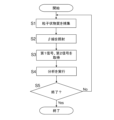
- 4 is a flowchart showing an analysis operation in the analysis device.
- FIG. 13 is a diagram showing an example of a verification result as to whether fluorescent X-rays can be generated and detected from an analysis target.
- FIG. 11 is a diagram showing the configuration of a detection unit according to a second embodiment.
- FIG. 13 is a diagram showing the configuration of a detection unit according to a third embodiment.
- the analysis device 100 analyzes, for example, combustion processes in factories, brakes of various transport devices (automobiles, ships, etc.), tires, internal combustion engines, steam engines, exhaust gas purification devices and motors, natural disasters such as volcanic eruptions, particulate matter FP generated by mining development, and particulate matter FP contained in the atmosphere.
- particulate matter FP containing silver (Ag), tin (Sn), etc. can be analyzed.
- the analysis device 100 can obtain, as analysis results, the mass concentration of the particulate matter FP and information on the elements contained in the particulate matter FP (for example, the elements contained and the content of the elements).
- Mass concentration of particulate matter FP is defined as the mass of particulate matter contained in the total volume of collected gas, expressed as a value per unit volume of collected gas, e.g., in ⁇ g/ m3 .
- the “content of an element” has the following two definitions.
- the “content of an element” is defined as the mass of a target element (or substance) contained in the total mass of collected particulate matter FP, expressed as a ratio of the mass of the target element (substance) to the total weight of the particulate matter (units are, for example, mg/mg).
- the “content of an element” is defined as the amount of a specific element contained in particulate matter contained in the total volume of collected gas, expressed as a value per unit volume of gas (units are, for example, ng/ m3 ).
- Fig. 1 is a diagram showing the configuration of the analysis device.
- Fig. 2 is a diagram showing the detailed configuration of the ⁇ -ray irradiation unit and the detection unit.
- the analysis device 100 includes a collection filter 1, a collection device 3, a ⁇ -ray generation unit 5, a detection unit 7, and an analysis unit 9.
- the collection filter 1 is a tape-like member formed by laminating a collection layer (sometimes called a collection region) made of a porous fluororesin material having pores capable of collecting particulate matter FP onto a reinforcing layer made of a nonwoven fabric of a polymer material (such as polyethylene). With the above-mentioned configuration, the collection filter 1 allows gas to flow in the thickness direction of the collection filter 1, while at the same time improving its strength. It is also possible to make the collection filter 1 less likely to become electrically charged. Note that other filters, such as a single-layer glass filter or a single-layer fluororesin material filter, can also be used as the collection filter 1.
- one end of the collection filter 1 in the longitudinal direction is connected to the take-up reel 11a, and the other end is connected to the feed reel 11b.
- the take-up reel 11a can be rotated in a predetermined direction, for example, by a motor (not shown). With this configuration, by rotating the take-up reel 11a, the collection filter 1 is fed from the feed reel 11b and wound up onto the take-up reel 11a. In other words, the collection filter 1 can be moved in the longitudinal direction of the collection filter 1 (the direction indicated by the thick arrow in Figure 1) by the rotation of the take-up reel 11a.
- the mechanism for moving the collection filter 1 is not limited to the mechanism described above.
- a pin may be provided in the length direction of the collection filter 1, and the movement direction of the collection filter 1 may be changed by this pin.
- the collection filter 1 may be provided with a tension controller that adjusts its tension.
- the collection device 3 causes the collection filter 1 to collect particulate matter FP suspended in the measurement atmosphere.
- the collection device 3 has a suction member 31 and a discharge member 33.
- the suction member 31 is disposed directly below the surface of the collection filter 1 on the reinforcing layer side.
- the suction member 31 is formed with a first opening 31a connected to a suction pump 35.
- the discharge member 33 is disposed in a position facing the suction member 31, directly above the surface of the collection filter 1 facing the collection area.
- a second opening 33a is formed in the discharge member 33 so as to face the first opening 31a.
- the second opening 33a can discharge the particulate matter FP captured via the capture member 37 toward the collection filter 1 by the suction force of the first opening 31a.
- the particulate matter FP discharged from the discharge member 33 is captured by the collection filter 1.
- the collection member 37 may have various devices for collecting particulate matter FP. For example, when particulate matter FP in the atmosphere is to be analyzed, the collection member 37 may have a classifier that classifies the particulate matter FP. Also, for example, when particulate matter FP in exhaust gas is to be analyzed, the collection member 37 may have a sampling section (e.g., a sampling probe, etc.).
- the ⁇ -ray generating unit 5 is disposed at the second opening 33a of the discharge member 33, and irradiates ⁇ -rays to the particulate matter FP captured by the collection filter 1.
- the ⁇ -ray generating unit 5 has a ⁇ -ray source 51.
- the ⁇ -ray source 51 irradiates ⁇ -rays toward the particulate matter FP captured by the collection filter 1.
- the ⁇ -ray source 51 is, for example, carbon-14 ( 14C ), strontium-90 ( 90Sr ), or promethium-147 ( 147Pm ). By using these as the ⁇ -ray source 51, it is possible to suppress the generation of unnecessary radiation such as ⁇ -rays.
- the ⁇ -ray generating unit 5 may have a limiting member 53.
- the limiting member 53 adjusts the intensity of the ⁇ -rays irradiated toward the particulate matter FP by blocking a portion of the ⁇ -rays generated from the ⁇ -ray source 51.
- the limiting member 53 is, for example, a plate-shaped member made of acrylic.
- the detection unit 7 can be disposed, for example, at the first opening 31a of the suction member 31. This allows the detection unit 7 to be disposed opposite the ⁇ -ray generation unit 5.
- the detection unit 7 detects ⁇ -rays (called transmitted ⁇ -rays) that are generated from the ⁇ -ray generation unit 5 and pass through the particulate matter FP and the collection filter 1, and fluorescent X-rays generated by irradiating the particulate matter FP with ⁇ -rays.
- the detection unit 7 of this embodiment simultaneously detects the particulate matter FP and ⁇ -rays that pass through the collection filter 1, and the fluorescent X-rays generated from the particulate matter FP using separate detectors.
- the detection unit 7 has a first scintillator 71, a first photodetector 73, a second scintillator 75, and a second photodetector 77.
- the first scintillator 71 can be arranged, for example, opposite the ⁇ -ray generating unit 5 at the first opening 31a.
- the first scintillator 71 generates light in response to the passing ⁇ -rays.
- the first scintillator 71 is a member that generates light when passing ⁇ -rays are incident on it, and is, for example, a scintillator made of a low-density material such as a plastic scintillator made of polyvinyl toluene.
- the first photodetector 73 detects light (called the first light) generated by the first scintillator 71 and outputs a first signal. That is, the first photodetector 73 outputs a first signal by detecting ⁇ rays passing through the first scintillator 71.
- the first photodetector 73 is a detector that detects light and outputs a signal, such as a SiPM (Silicon PhotoMultiplier), a photomultiplier tube, or a silicon semiconductor detector.
- the second scintillator 75 is disposed below the first scintillator 71, facing the ⁇ -ray generating unit 5 at the first opening 31a.
- the second scintillator 75 generates light corresponding to the fluorescent X-rays generated from the particulate matter FP and passed through the first scintillator 71.
- the second scintillator 75 is a member that generates light when X-rays are incident on it, and is a member made of an inorganic material such as cesium iodide (CsI) or sodium iodide (NaI).
- the second photodetector 77 detects the light (called the second light) generated in the second scintillator 75 and outputs a second signal. That is, the second photodetector 77 outputs a first signal by detecting fluorescent X-rays generated by the particulate matter FP in the second scintillator 75.
- the second photodetector 77 is, for example, a detector that detects light such as a SiPM (Silicon PhotoMultiplier), a photomultiplier tube, or a silicon semiconductor detector and outputs a signal.
- the detection unit 7 further has a light shielding member 79.
- the light shielding member 79 prevents external light from entering the detection unit 7.
- the light shielding member 79 prevents external light from entering the first photodetector 73 and the second photodetector 77. This makes it possible to suppress the incidence of light other than the light (first light, second light) generated by the scintillator described above into the first photodetector 73 and the second photodetector 77. As a result, it is possible to more accurately detect transmitted ⁇ rays and fluorescent X-rays generated from the particulate matter FP.
- the analysis unit 9 is a computer system having a CPU, RAM, ROM, storage devices such as HDD and SSD, various interfaces, a display, etc.
- the analysis unit 9 controls each component of the analysis device 100 and performs various information processing related to the analysis device 100.
- the analysis unit 9 has a calculation unit 91 and a display unit 93.
- the calculation unit 91 is composed of the CPU, storage device, and various interfaces of the analysis unit 9, and controls each component of the analysis device 100 and performs various information processing related to the analysis device 100.
- the calculation unit 91 realizes the control of each component of the analysis device 100 and the various information processing related to the analysis device 100 by software that is stored in the storage device of the computer system that constitutes the analysis unit 9 and can be executed by the analysis unit 9.
- the calculation unit 91 may realize part of the above control and information processing by hardware.
- the calculation unit 91 controls the suction pump 35 to cause the collection filter 1 to collect the particulate matter FP.
- the calculation unit 91 also controls the motor that rotates the take-up reel 11a to control the longitudinal movement of the collection filter 1.
- the calculation unit 91 controls the ⁇ -ray source 51 to control the ⁇ -rays irradiated to the particulate matter FP.
- the calculation unit 91 calculates information about the mass concentration of the particulate matter FP based on the first signal input from the first photodetector 73.
- the calculation unit 91 also calculates information about the elements contained in the particulate matter FP based on the second signal input from the second photodetector 77.
- the display unit 93 is a display for the analysis unit 9, and displays various information related to the analysis device 100 and the analysis results of the particulate matter FP (information related to mass concentration, information related to elements).
- the display unit 93 is, for example, a liquid crystal display, an organic EL display, or the like.
- Fig. 3 is a flow chart showing the analysis operation in the analysis apparatus.
- a process is executed to collect the particulate matter FP suspended in the measurement atmosphere on the collection filter 1 (step S1).
- the calculation unit 91 of the analysis unit 9 operates the suction pump 35 to collect the particulate matter FP on the collection filter 1.
- the calculation unit 91 generates beta rays from the beta ray source 51 (step S2). This causes beta rays to be irradiated onto the particulate matter FP. A portion of the beta rays irradiated onto the particulate matter FP passes through the particulate matter FP and the collection filter 1 and enters the detection unit 7. In addition, by irradiating the particulate matter FP with beta rays, fluorescent X-rays are generated from the particulate matter FP, which pass through the collection filter 1 and enter the detection unit 7.
- the calculation unit 91 detects the ⁇ rays and fluorescent X-rays incident on the detection unit 7 (step S3).
- the transmitted ⁇ rays that have passed through the particulate matter FP and the collection filter 1 are incident on the first scintillator 71, causing light (first light) to be generated in the first scintillator 71.
- the first photodetector 73 which detects the first light, outputs a first signal.
- the calculation unit 91 receives this first signal from the first photodetector 73 as a signal representing the intensity of the transmitted ⁇ rays.
- the first scintillator 71 is made of a low-density material such as a plastic scintillator. In this case, most of the passing ⁇ rays do not pass through the first scintillator 71, while the fluorescent X-rays from the particulate matter FP pass through the first scintillator 71 and enter the second scintillator 75. As a result, a second light caused by the fluorescent X-rays is generated in the second scintillator 75.
- the second photodetector 77 which detects the second light, outputs a second signal.
- the calculation unit 91 receives this second signal from the second photodetector 77 as a signal representing the intensity of the fluorescent X-rays generated from the particulate matter FP.
- the calculation unit 91 After acquiring the first signal corresponding to the passing ⁇ rays and the second signal corresponding to the fluorescent X-rays from the particulate matter FP, the calculation unit 91 performs an analysis of the particulate matter FP based on these signals (step S4). Specifically, the calculation unit 91 calculates the mass concentration of the particulate matter FP based on, for example, the intensity of the passing ⁇ rays represented in the first signal. The calculation unit 91 also identifies elements contained in the particulate matter FP based on, for example, the energy and intensity of the fluorescent X-rays represented in the second signal, and calculates the content of those elements in the particulate matter FP.
- the calculation unit 91 causes the display unit 93 to display the analysis results of the particulate matter FP. Furthermore, for example, when the mass concentration of the particulate matter FP exceeds a predetermined threshold value, or when the particulate matter FP contains a specific element at a predetermined content or more, the calculation unit 91 may notify an alarm. For example, the alarm can be notified by displaying an alarm on the display unit 93, emitting a sound, or the like.
- step S5 After the analysis is completed, for example, if a command is given to stop the analysis of the particulate matter FP ("Yes" in step S5), the analysis operation in the analysis device 100 stops. On the other hand, if a command is not given to stop the analysis of the particulate matter FP ("No" in step S5), the analysis operation in the analysis device 100 continues. Specifically, the calculation unit 91 moves the collection filter 1 in the length direction by rotating the take-up reel 11a, and positions the portion of the collection filter 1 where no particulate matter FP has been collected directly below the discharge member 33. Thereafter, steps S1 to S4 described above are performed to perform a new analysis of the particulate matter FP.
- the calculation unit 91 can simultaneously obtain a first signal for calculating information related to the mass concentration of the particulate matter FP and a second signal for calculating information related to the elements contained in the particulate matter FP.
- the analysis results of the particulate matter FP (information related to mass concentration, information related to elements) can be obtained in a short period of time.
- Figure 4 shows an example of the results of a verification as to whether fluorescent X-rays can be generated and detected from an analysis target by irradiating the analysis target with ⁇ -rays.
- the photodetector when the analysis target (lead plate) is irradiated with ⁇ -rays, the photodetector is able to detect a significant X-ray intensity compared to the background at the energy value of the K ⁇ rays of lead (Pb).
- the photodetector is able to detect the fluorescent X-rays generated when the analysis target is irradiated with ⁇ -rays.
- the background corresponds to the intensity of light (X-rays) detected by the photodetector when no ⁇ -rays are generated from the ⁇ -ray source.
- the passing ⁇ rays and the fluorescent X-rays are detected by separate detectors.
- the passing ⁇ rays and the fluorescent X-rays can also be detected by a common detector.
- the detection unit 7' has a first scintillator 71, a second scintillator 75, and a third photodetector 81, as shown in Fig. 5.
- Fig. 5 is a diagram showing the configuration of the detection unit of the second embodiment.
- the first scintillator 71 and second scintillator 75 of the detection unit 7' are the same as those in the first embodiment, so a description thereof will be omitted here.
- the third photodetector 81 is disposed below the second scintillator 75, and simultaneously detects a first light generated when passing ⁇ rays are incident on the first scintillator 71, and a second light generated when fluorescent X-rays are incident on the second scintillator 75.
- the third photodetector 81 is a detector that detects light such as, for example, a SiPM (Silicon PhotoMultiplier), a photomultiplier tube, a silicon semiconductor detector, etc., and outputs a signal.
- the number of detectors for detecting transmitted beta rays and fluorescent X-rays can be reduced, making the device configuration of the analysis device 100 simpler.
- the third photodetector 81 simultaneously detects the first light and the second light. Therefore, the detection signal output from the third photodetector 81 by detecting these lights is a signal obtained by adding together a first signal caused by the first light (passing ⁇ rays) and a second signal caused by the second light (fluorescent X-rays). In order to measure the passing ⁇ rays and fluorescent X-rays from this detection signal, the calculation unit 91 separates the first signal and the second signal from this detection signal.
- a pulsed detection signal is output from the photodetector when radiation is detected.
- the peak intensity of the pulsed detection signal corresponds to the energy of the detected radiation.
- the number of pulsed detection signals per unit time corresponds to the intensity of the detected radiation.
- the energy value of the fluorescent X-rays generated from the subject of analysis is specific to the elements contained in the subject of analysis.
- the calculation unit 91 separates a first signal caused by passing ⁇ rays and a second signal caused by fluorescent X-rays based on the peak intensity of the pulsed detection signal output from the third photodetector 81.
- the first signal and the second signal can be separated as follows.
- the calculation unit 91 first identifies the peak intensity of the input pulsed detection signal and calculates an energy value corresponding to this peak intensity. If the calculated energy value does not correspond to the energy value of the fluorescent X-rays of an element predicted to be contained in the analysis target, the calculation unit 91 can determine that the detection signal is the first signal.
- the calculation unit 91 can calculate a second signal (the count value of the detection signal caused by the fluorescent X-rays) by subtracting the count value corresponding to the intensity of the component of the passing beta rays having that energy value from the count value of the detection signal.
- the pulse width of the detection signal also corresponds to the energy value of the detected radiation. Therefore, the calculation unit 91 can also separate the first signal and the second signal based on the pulse width of the detection signal output from the third photodetector 81. For example, the calculation unit 91 identifies the pulse width of the input pulsed detection signal and calculates the energy value corresponding to this pulse width. If the calculated energy value does not correspond to the energy value of the fluorescent X-rays of the element predicted to be contained in the analysis target, the calculation unit 91 can determine that the detection signal is the first signal. Note that the second signal can be separated using a method similar to that described above.
- the first scintillator 71 and the first photodetector 73 for detecting passing ⁇ -rays, and the second scintillator 75 and the second photodetector 77 for detecting fluorescent X-rays were both disposed at the first opening 31a of the suction member 31.
- the detection unit 7'' of the third embodiment can be configured to detect fluorescent X-rays, that is, the second scintillator 75' and the second photodetector 77', disposed outside the suction member 31.
- the second scintillator 75' and the second photodetector 77' can be disposed at any position on a sphere having a predetermined radius from the position where the particulate matter FP of the collection filter 1 is collected. Note that it is preferable to dispose the second scintillator 75' and the second photodetector 77' as close as possible to the position where the particulate matter FP of the collection filter 1 is collected (that is, it is preferable to make the above-mentioned predetermined radius small).
- the second scintillator 75' and the second photodetector 77' can be positioned on the side of the collection filter 1 where the particulate matter FP is captured, at a predetermined distance from the position where the particulate matter FP is captured.
- the second scintillator 75' and the second photodetector 77' can be positioned on the opposite side of the collection filter 1 from the side where the particulate matter FP is captured.
- FIG. 6 is a diagram showing the configuration of the detection unit of the third embodiment.
- the detection unit 7'' having the above configuration can be realized by providing the above-mentioned second scintillator 75' and second photodetector 77' to an existing analysis device in which a configuration for detecting passing ⁇ rays (first scintillator 71 and first photodetector 73) is provided in the first opening 31a.
- the detection unit 7'' has a configuration that makes it easy to expand an existing analysis device.
- An analysis device (e.g., analysis device 100) includes a ⁇ -ray source (e.g., ⁇ -ray source 51), a detection unit (e.g., detection units 7, 7', 7''), and an analysis unit (e.g., analysis unit 9).
- the ⁇ -ray source irradiates an analysis target with ⁇ -rays.
- the detection unit simultaneously detects transmitted ⁇ -rays that have passed through the analysis target and fluorescent X-rays generated by irradiating the analysis target with the ⁇ -rays, and outputs a detection signal.
- the analysis unit obtains, from the detection signal, a first signal generated by detecting the transmitted ⁇ -rays and a second signal generated by detecting the fluorescent X-rays.
- the analysis unit also calculates information regarding the mass concentration of the analysis target based on the first signal, and calculates information regarding the elements contained in the analysis target based on the second signal.
- the detection unit simultaneously detects the passing beta rays and the fluorescent X-rays and outputs a detection signal. That is, the detection signal includes a first signal derived from the passing beta rays and a second signal derived from the fluorescent X-rays.
- the analysis unit calculates information regarding the mass concentration of the object of analysis based on the first signal, and calculates information regarding the elements contained in the object of analysis based on the second signal.
- the above analytical device can calculate information about the mass concentration of the analysis target and information about the elements contained in the analysis target with a simple device configuration. Furthermore, since the detection unit can simultaneously detect transmitted beta rays and fluorescent X-rays, the analysis results of the analysis target (mass concentration and information about the elements contained in the analysis target) can be obtained in a short period of time.
- the detection unit may have a first scintillator (e.g., first scintillator 71), a second scintillator (e.g., second scintillator 75, 75'), and a light detection unit.
- the first scintillator is disposed opposite the ⁇ -ray source and generates a first light when passing ⁇ -rays are incident thereon.
- the second scintillator is disposed opposite the ⁇ -ray source and generates a second light when fluorescent X-rays are incident thereon.
- the light detection unit detects the first light and the second light and outputs a detection signal. This allows the passing ⁇ -rays and fluorescent X-rays to be converted into the first light and the second light, respectively, and the passing ⁇ -rays and fluorescent X-rays can be easily detected.
- the light detection unit may have a first light detector (e.g., first light detector 73) that detects the first light and outputs a first signal, and a second light detector (e.g., second light detectors 77, 77') that detects the second light and outputs a second signal.
- first light detector e.g., first light detector 73
- second light detector e.g., second light detectors 77, 77'
- the light detection unit may have a third light detector (e.g., third light detector 81) that detects both the first light and the second light and outputs a detection signal. This allows the first light and the second light to be detected by a single light detector, simplifying the device configuration.
- a third light detector e.g., third light detector 81
- the analysis unit may separate the first signal and the second signal from the detection signal based on the pulse width of the detection signal. This makes it possible to accurately separate the first signal and the second signal using the pulse width of the detection signal.
- the analysis unit may separate the first signal and the second signal from the detection signal based on the peak intensity of the detection signal. This allows the first signal and the second signal to be accurately separated using the intensity of the detection signal.
- the subject of analysis may be particulate matter (e.g., particulate matter FP).
- the analytical device may further include a collection device (e.g., collection device 3) that collects particulate matter in a collection filter (e.g., collection filter 1).
- the ⁇ -ray source and the detection unit may be provided in the collection device. This allows the mass concentration of the particulate matter and information about the elements contained in the particulate matter to be calculated in a short period of time. Furthermore, providing the ⁇ -ray source and the detection unit in the collection device allows the analytical device to be made compact.
- the analysis method includes the following steps: A step of irradiating the object to be analyzed with ⁇ rays (for example, step S2). A step of simultaneously detecting the transmitted ⁇ -rays that have passed through the object to be analyzed and the fluorescent X-rays generated by irradiating the object to be analyzed with ⁇ -rays, and outputting a detection signal (for example, step S2). A step of acquiring a first signal generated by detecting passing ⁇ rays and a second signal generated by detecting fluorescent X-rays from the detection signal (for example, step S3). A step of calculating information regarding the mass concentration of the analyte based on the first signal, and calculating information regarding the elements contained in the analyte based on the second signal (for example, step S4).
- the passing beta rays and fluorescent X-rays generated by irradiating the analysis target with beta rays are detected simultaneously, and a detection signal is output. That is, the detection signal includes a first signal derived from the passing beta rays and a second signal derived from the fluorescent X-rays. Furthermore, in the above analysis method, information regarding the mass concentration of the analysis target is calculated based on the first signal, and information regarding the elements contained in the analysis target is calculated based on the second signal.
- the above analysis method detects transmitted beta rays and fluorescent X-rays simultaneously, making it possible to obtain the analysis results of the subject (mass concentration and information on the elements contained in the subject) in a short period of time.
- Other devices may be controlled based on the analysis results of the analysis target output by the analysis unit 9 of the above-mentioned analysis device 100.
- the analysis target is particulate matter FP generated in a waste incineration facility
- the analysis result may be output as to whether or not the particulate matter FP contains harmful substances (elements), and when this analysis result is output, a specific device in the waste incineration facility may be operated.
- the above-mentioned analytical device 100 can be combined with another analytical device (e.g., a gas analyzer) to construct a system for performing more detailed analysis of the subject of analysis.
- another analytical device e.g., a gas analyzer
- a ⁇ -ray source that generates ⁇ -rays and an X-ray source that generates X-rays or the like to generate fluorescent X-rays from the particulate matter FP may be provided separately.
- the ⁇ -ray source and the X-ray source can be arranged adjacent to each other at the second opening 33a. This allows ⁇ -rays and fluorescent X-rays to be detected simultaneously by a single detection unit 7 arranged at the first opening 31a.
- the X-ray source can also be arranged on the opposite side of the collection filter 1 to the side where the particulate matter FP is collected.
- the ⁇ -ray source 51 may be disposed at a position away from the second opening 33a. Specifically, the ⁇ -ray source 51 may be disposed at a position away from the second opening 33a, tilted with respect to the extension direction of the second opening 33a. In this case, the ⁇ -ray source 51 irradiates ⁇ -rays obliquely toward the second opening 33a. This means that the ⁇ -ray source 51 does not interfere with the flow of particulate matter FP flowing through the second opening 33a. As a result, the particulate matter FP can be collected evenly and without unevenness on the collection surface of the collection filter 1.
- the present invention can be widely applied to microparticulate matter analysis devices that analyze microparticulate matter suspended in a measurement space.
- Analysis device 1 Collection filter 11a: Take-up reel 11b: Delivery reel 3: Collection device 31: Suction member 31a: First opening 33: Discharge member 33a: Second opening 35: Suction pump 37: Collection member 5: ⁇ -ray generation unit 51: ⁇ -ray source 53: Restriction member 7, 7', 7'': Detection unit 71: First scintillator 73: First photodetector 75, 75': Second scintillator 77, 77': Second photodetector 79: Light shielding member 81: Third photodetector 9: Analysis unit 91: Calculation unit 93: Display unit FP: Particulate matter
Landscapes
- Physics & Mathematics (AREA)
- Health & Medical Sciences (AREA)
- Life Sciences & Earth Sciences (AREA)
- Chemical & Material Sciences (AREA)
- Analytical Chemistry (AREA)
- Biochemistry (AREA)
- General Health & Medical Sciences (AREA)
- General Physics & Mathematics (AREA)
- Immunology (AREA)
- Pathology (AREA)
- Analysing Materials By The Use Of Radiation (AREA)
Abstract
分析対象の質量濃度と元素に関する分析結果を、簡便な装置構成により短時間に取得する。分析装置(100)は、β線源(51)と、検出部(7、7'、7'')と、分析部(9)と、を備える。β線源(51)は、分析対象にβ線を照射する。検出部(7、7'、7'')は、分析対象を通過した通過β線と、分析対象に当該β線を照射することにより生じた蛍光X線と、を同時に検出して検出信号を出力する。分析部(9)は、検出信号から、通過β線を検出することで生じた第1信号と、蛍光X線を検出することで生じた第2信号と、を取得する。分析部(9)は、第1信号に基づいて分析対象の質量濃度に関する情報を算出し、第2信号に基づいて分析対象に含まれる元素に関する情報を算出する。
Description
本発明は、分析対象の質量濃度と分析対象に含まれる元素に関する分析を行う分析装置、及び、当該分析装置による分析対象の分析方法に関する。
分析対象の分析を行う装置として、分析対象を通過したβ線量に基づいて分析対象の質量濃度を測定し、分析対象から発生する蛍光X線に基づいて分析対象に含まれる元素を分析可する装置が知られている(例えば、特許文献1)。
上記の装置では、分析対象である粒子状物質を捕集フィルタに捕集して質量濃度を測定し、その後、捕集フィルタを移動させて粒子状物質の捕集領域を移動させ、移動後の位置で粒子状物質から蛍光X線を発生させて粒子状物質に含まれる元素に関する分析を行っていた。つまり、従来の装置では、質量濃度を測定する箇所と、元素に関する分析を行う箇所とが個別に設けられていた。このため、従来の装置は、装置構成が複雑となることがあった。また、質量濃度と元素分析とを個別に実行するために、分析結果を得るためにある程度の時間を必要とし、より高速な分析結果の取得に対応できない可能性がある。
本発明の目的は、分析対象の質量濃度と元素に関する分析結果を、簡便な装置構成により短時間に取得することにある。
以下に、課題を解決するための手段として複数の態様を説明する。これら態様は、必要に応じて任意に組み合せることができる。
本発明の一見地に係る分析装置は、β線源と、検出部と、分析部と、を備える。β線源は、分析対象にβ線を照射する。検出部は、分析対象を通過した通過β線と、分析対象に当該β線を照射することにより生じた蛍光X線と、を同時に検出して検出信号を出力する。分析部は、検出信号から、通過β線を検出することで生じた第1信号と、蛍光X線を検出することで生じた第2信号と、を取得する。また、分析部は、第1信号に基づいて分析対象の質量濃度に関する情報を算出し、第2信号に基づいて分析対象に含まれる元素に関する情報を算出する。
本発明の一見地に係る分析装置は、β線源と、検出部と、分析部と、を備える。β線源は、分析対象にβ線を照射する。検出部は、分析対象を通過した通過β線と、分析対象に当該β線を照射することにより生じた蛍光X線と、を同時に検出して検出信号を出力する。分析部は、検出信号から、通過β線を検出することで生じた第1信号と、蛍光X線を検出することで生じた第2信号と、を取得する。また、分析部は、第1信号に基づいて分析対象の質量濃度に関する情報を算出し、第2信号に基づいて分析対象に含まれる元素に関する情報を算出する。
本発明の発明者は、分析対象にβ線を照射したときに、分析対象を通過する通過β線が発生すると同時に、分析対象から蛍光X線が発生することを見いだした。上記の分析装置においては、検出部が、通過β線と蛍光X線とを同時に検出して検出信号を出力している。すなわち、検出信号には、通過β線に由来する第1信号と、蛍光X線に由来する第2信号と、が含まれる。また、分析部が、第1信号に基づいて分析対象の質量濃度に関する情報を算出し、第2信号に基づいて分析対象に含まれる元素に関する情報を算出している。
このように、上記の分析装置では、簡素な装置構成により、分析対象の質量濃度に関する情報と分析対象に含まれる元素に関する情報とを算出できる。また、検出部が、通過β線と蛍光X線とを同時に検出できるので、分析対象の分析結果(質量濃度と分析対象に含まれる元素に関する情報)を短時間に取得できる。
検出部は、第1シンチレータと、第2シンチレータと、光検出部と、を有してもよい。第1シンチレータは、β線源と対向して配置され、通過β線が入射することで第1光を発生する。第2シンチレータは、β線源と対向して配置され、蛍光X線が入射することで第2光を発生する。光検出部は、第1光と第2光とを検出して検出信号を出力する。これにより、通過β線と蛍光X線とをそれぞれ第1光と第2光に変換して、簡便に通過β線と蛍光X線とを検出できる。
光検出部は、第1光を検出して第1信号を出力する第1光検出器と、第2光を検出して第2信号を出力する第2光検出器と、を有してもよい。これにより、第1光と第2光とをそれぞれ個別の光検出器により同時に検出できる。この結果、取得した信号に対して信号分離処理を行うことなく、より簡便に第1信号と第2信号を取得できる。
光検出部は、第1光と第2光とを両方検出して検出信号を出力する第3光検出器を有してもよい。これにより、第1光と第2光を1つの光検出器により検出できるので、装置構成を簡便にできる。
分析部は、検出信号のパルス幅に基づいて、検出信号から第1信号と第2信号を分離してもよい。これにより、検出信号のパルス幅を用いて、第1信号と第2信号とを正確に分離できる。
分析部は、検出信号のピーク強度に基づいて、検出信号から第1信号と第2信号を分離してもよい。これにより、検出信号の強度を用いて、第1信号と第2信号とを正確に分離できる。
分析対象は粒子状物質であってもよい。この場合、分析装置は、粒子状物質を捕集フィルタに捕集する捕集装置をさらに備えてもよい。また、β線源と検出部は、捕集装置に設けられてもよい。これにより、粒子状物質の質量濃度と粒子状物質に含まれる元素に関する情報とを短時間に算出できる。また、β線源と検出部が捕集装置に設けられることで、分析装置をコンパクトにできる。
本発明の他の見地に係る分析方法は、以下のステップを備える。
◎分析対象にβ線を照射するステップ。
◎分析対象を通過した通過β線と、分析対象にβ線を照射することにより生じた蛍光X線と、を同時に検出して検出信号を出力するステップ。
◎検出信号から、通過β線を検出することで生じた第1信号と、蛍光X線を検出することで生じた第2信号と、を取得するステップ。
◎第1信号に基づいて分析対象の質量濃度に関する情報を算出し、第2信号に基づいて分析対象に含まれる元素に関する情報を算出するステップ。
◎分析対象にβ線を照射するステップ。
◎分析対象を通過した通過β線と、分析対象にβ線を照射することにより生じた蛍光X線と、を同時に検出して検出信号を出力するステップ。
◎検出信号から、通過β線を検出することで生じた第1信号と、蛍光X線を検出することで生じた第2信号と、を取得するステップ。
◎第1信号に基づいて分析対象の質量濃度に関する情報を算出し、第2信号に基づいて分析対象に含まれる元素に関する情報を算出するステップ。
上記の分析方法においては、分析対象にβ線を照射することにより生じた通過β線と蛍光X線とを同時に検出して検出信号を出力している。すなわち、検出信号には、通過β線に由来する第1信号と、蛍光X線に由来する第2信号と、が含まれる。また、上記の分析方法では、第1信号に基づいて分析対象の質量濃度に関する情報を算出し、第2信号に基づいて分析対象に含まれる元素に関する情報を算出している。
このように、上記の分析方法では、通過β線と蛍光X線とを同時に検出しているので、分析対象の分析結果(質量濃度と分析対象に含まれる元素に関する情報)を短時間に取得できる。
分析対象の質量濃度と元素に関する分析結果を、簡便な装置構成により短時間に取得できる。
1.第1実施形態
(1)分析装置の概要
分析装置100は、例えば、工場等における燃焼プロセス、各種の輸送装置(自動車や船舶等)のブレーキ、タイヤ、内燃機関、蒸気機関、排ガス浄化装置やモータ、火山の噴火といった自然災害、鉱山開発によって発生する粒子状物質FP、大気中に含まれる粒子状物質FPを分析対象とする。例えば、銀(Ag)、スズ(Sn)などを含む粒子状物質FPを分析対象とできる。分析装置100は、粒子状物質FPの質量濃度と、粒子状物質FPに含まれる元素に関する情報(例えば、含まれる元素と当該元素の含有量)と、を分析結果として取得できる。
(1)分析装置の概要
分析装置100は、例えば、工場等における燃焼プロセス、各種の輸送装置(自動車や船舶等)のブレーキ、タイヤ、内燃機関、蒸気機関、排ガス浄化装置やモータ、火山の噴火といった自然災害、鉱山開発によって発生する粒子状物質FP、大気中に含まれる粒子状物質FPを分析対象とする。例えば、銀(Ag)、スズ(Sn)などを含む粒子状物質FPを分析対象とできる。分析装置100は、粒子状物質FPの質量濃度と、粒子状物質FPに含まれる元素に関する情報(例えば、含まれる元素と当該元素の含有量)と、を分析結果として取得できる。
「粒子状物質FPの質量濃度」は、収集した気体の総体積中に含まれる粒子状物質の質量を、収集した気体の単位体積当たりの値として表したものとして定義され、例えば、μg/m3を単位とする。
一方、「元素の含有量」は、以下の二種類の定義を有する。1つ目の定義では、「元素の含有量」を、収集した粒子状物質FPの総質量に目的の元素(又は物質)がどのくらいの質量含まれているかを、粒子状物質の総重量に対する目的の元素(物質)の含有質量の割合として表したものとして定義する(単位は、例えば、mg/mg)。2つ目の定義では、「元素の含有量」を、収集した気体の総体積中に含まれる粒子状物質内に含まれる特定の元素の元素量を、気体の単位体積当たりの値として表したものとして定義する(単位は、例えば、ng/m3)。
(2)分析装置の構成
以下、図1及び図2を用いて、分析装置100構成を説明する。図1は、分析装置の構成を示す図である。図2は、β線照射部と検出部の詳細構成を示す図である。分析装置100は、捕集フィルタ1と、捕集装置3と、β線発生部5と、検出部7と、分析部9と、を備える。
以下、図1及び図2を用いて、分析装置100構成を説明する。図1は、分析装置の構成を示す図である。図2は、β線照射部と検出部の詳細構成を示す図である。分析装置100は、捕集フィルタ1と、捕集装置3と、β線発生部5と、検出部7と、分析部9と、を備える。
捕集フィルタ1は、例えば、高分子材料(ポリエチレンなど)の不織布にて形成された補強層上に、粒子状物質FPを捕集可能な孔を有する多孔質のフッ素樹脂系材料にて形成された捕集層(捕集領域と呼ぶこともある)を積層して形成された、テープ状の部材である。上記の構成により、捕集フィルタ1は、捕集フィルタ1の厚み方向にガス流通可能となると同時に、その強度を向上できる。また、捕集フィルタ1を帯電しにくくできる。なお、捕集フィルタ1としては、例えば、1層のガラスフィルタや、1層のフッ素樹脂系材料のフィルタなどの他のフィルタを用いることもできる。
例えば、捕集フィルタ1の長さ方向の一端は巻き取りリール11aに接続され、他端は送り出しリール11bに接続されている。巻き取りリール11aは、例えば、モータ(図示せず)などにより所定方向に回転可能となっている。この構成により、巻き取りリール11aを回転することにより、捕集フィルタ1は、送り出しリール11bから送り出され、巻き取りリール11aに巻き取られる。すなわち、捕集フィルタ1は、巻き取りリール11aの回転により、捕集フィルタ1の長さ方向(図1では太矢印にて示す方向)に移動できる。
なお、捕集フィルタ1を移動させる機構は、上記の機構に限られない。例えば、捕集フィルタ1の長さ方向にピンを設け、このピンにより捕集フィルタ1の移動方向が変更可能となっていてもよい。また、捕集フィルタ1にその張力を調整するテンションコントローラを設けてもよい。
捕集装置3は、測定雰囲気中に浮遊している粒子状物質FPを捕集フィルタ1に捕集させる。捕集装置3は、吸引部材31と、排出部材33と、を有する。吸引部材31は、捕集フィルタ1の補強層側の面の直下に配置されている。吸引部材31には、吸引ポンプ35に接続された第1開口部31aが形成されている。
排出部材33は、捕集フィルタ1の捕集領域側の面の直上において、吸引部材31と対向する位置に配置される。排出部材33には、第1開口部31aと対向するように第2開口部33aが形成されている。第2開口部33aは、第1開口部31aの吸引力によって、捕集部材37を介して捕集した粒子状物質FPを、捕集フィルタ1に向けて排出できる。排出部材33から排出された粒子状物質FPは、捕集フィルタ1により捕集される。
なお、捕集部材37は、粒子状物質FPを捕集するための各種装置等を有していてもよい。例えば、大気中の粒子状物質FPを分析対象とする場合には、捕集部材37は、粒子状物質FPを分級する分級器を有してもよい。また、例えば、排ガス中の粒子状物質FPを分析対象とする場合には、捕集部材37は、サンプリング部(例えば、サンプリングプローブなど)を有してもよい。
β線発生部5は、排出部材33の第2開口部33aに配置され、捕集フィルタ1に捕集された粒子状物質FPにβ線を照射する。図2に示すように、β線発生部5は、β線源51を有する。β線源51は、捕集フィルタ1に捕集された粒子状物質FPに向けてβ線を照射する。β線源51は、例えば、炭素14(14C)、ストロンチウム90(90Sr)、プロメチウム147(147Pm)である。これらをβ線源51として用いることで、γ線などの不要な放射線の発生を抑制できる。
β線発生部5は、制限部材53を有してもよい。制限部材53は、β線源51から発生したβ線の一部を遮蔽することで、粒子状物質FPに向けて照射するβ線の強度を調節する。制限部材53は、例えば、アクリル製の板状部材である。
検出部7は、例えば、吸引部材31の第1開口部31aに配置できる。これにより、検出部7を、β線発生部5に対向して配置できる。検出部7は、β線発生部5から発生し粒子状物質FPと捕集フィルタ1を通過したβ線(通過β線と呼ぶ)と、粒子状物質FPにβ線を照射することで発生した蛍光X線と、を検出する。図2に示すように、本実施形態の検出部7は、粒子状物質FPと捕集フィルタ1を通過したβ線と、粒子状物質FPから発生した蛍光X線とを個別の検出器により同時に検出する。具体的には、検出部7は、第1シンチレータ71と、第1光検出器73と、第2シンチレータ75と、第2光検出器77と、を有する。
第1シンチレータ71は、例えば、第1開口部31aにおいてβ線発生部5と対向して配置できる。第1シンチレータ71は、通過β線に応じた光を発生する。第1シンチレータ71は、通過β線が入射されたときに光を発生する部材であり、例えば、ポリビニルトルエン製のプラスチックシンチレータなどの密度の低い材料にて構成されたシンチレータである。
第1光検出器73は、第1シンチレータ71にて発生した光(第1光と呼ぶ)を検出して第1信号を出力する。すなわち、第1光検出器73は、第1シンチレータ71にて通過β線を検出することで第1信号を出力する。第1光検出器73は、例えば、SiPM(Silicon PhotoMultiplier、シリコン光電子増倍管)、光電子増倍管、シリコン半導体検出器などの光を検出して信号を出力する検出器である。
第2シンチレータ75は、第1開口部31aにおいてβ線発生部5と対向した状態で、第1シンチレータ71の下部に配置される。第2シンチレータ75は、粒子状物質FPから発生し第1シンチレータ71を通過した蛍光X線に応じた光を発生する。第2シンチレータ75は、X線が入射されたときに光を発生する部材であり、例えば、ヨウ化セシウム(CsI)、ヨウ化ナトリウム(NaI)などの無機材料の部材である。
第2光検出器77は、第2シンチレータ75にて発生した光(第2光と呼ぶ)を検出して第2信号を出力する。すなわち、第2光検出器77は、第2シンチレータ75にて粒子状物質FPにて発生した蛍光X線を検出することで第1信号を出力する。第2光検出器77は、例えば、SiPM(Silicon PhotoMultiplier、シリコン光電子増倍管)、光電子増倍管、シリコン半導体検出器などの光を検出して信号を出力する検出器である。
検出部7は、光遮蔽部材79をさらに有する。光遮蔽部材79は、外部からの光が検出部7に入射することを防止する。すなわち、光遮蔽部材79は、第1光検出器73及び第2光検出器77に外部の光が入射することを防止する。これにより、第1光検出器73及び第2光検出器77に、上記のシンチレータにて発生した光(第1光、第2光)以外の光が入射することを抑制できる。この結果、通過β線及び粒子状物質FPから発生した蛍光X線をより正確に検出できる。
分析部9は、CPU、RAM、ROM、HDD、SSDなどの記憶装置、各種インターフェース、ディスプレイなどを有するコンピュータシステムである。分析部9は、分析装置100の各構成要素の制御と、分析装置100に関する各種情報処理とを実行する。分析部9は、演算部91と、表示部93と、を有する。
演算部91は、分析部9のCPU、記憶装置、各種インターフェースにて構成され、分析装置100の各構成要素の制御と、分析装置100に関する各種情報処理とを実行する。演算部91は、分析装置100の各構成要素の制御、分析装置100に関する各種情報処理を、分析部9を構成するコンピュータシステムの記憶装置に記憶され、分析部9にて実行可能なソフトウェアによって実現する。演算部91は、上記制御及び情報処理の一部をハードウェア的に実現してもよい。
具体的には、演算部91は、吸引ポンプ35を制御して、捕集フィルタ1に粒子状物質FPを捕集させる。また、演算部91は、巻き取りリール11aを回転させるモータを制御して、捕集フィルタ1の長さ方向の移動を制御する。演算部91は、β線源51を制御して、粒子状物質FPに照射するβ線を制御する。演算部91は、第1光検出器73から入力した第1信号に基づいて、粒子状物質FPの質量濃度に関する情報を算出する。また、第2光検出器77から入力した第2信号に基づいて、粒子状物質FPに含まれる元素に関する情報を算出する。
表示部93は、分析部9のディスプレイであり、分析装置100に関する各種情報、粒子状物質FPの分析結果(質量濃度に関する情報、元素に関する情報)を表示する。表示部93は、例えば、液晶ディスプレイ、有機ELディスプレイなどのディスプレイである。
(3)分析装置における分析動作
図3を用いて、分析装置100における粒子状物質FPの分析動作を説明する。図3は、分析装置における分析動作を示すフローチャートである。まず、測定雰囲気中に浮遊する粒子状物質FPを捕集フィルタ1に捕集する処理が実行される(ステップS1)。具体的には、分析部9の演算部91が、吸引ポンプ35を動作させて、粒子状物質FPを捕集フィルタ1に捕集させる。
図3を用いて、分析装置100における粒子状物質FPの分析動作を説明する。図3は、分析装置における分析動作を示すフローチャートである。まず、測定雰囲気中に浮遊する粒子状物質FPを捕集フィルタ1に捕集する処理が実行される(ステップS1)。具体的には、分析部9の演算部91が、吸引ポンプ35を動作させて、粒子状物質FPを捕集フィルタ1に捕集させる。
上記捕集動作中、又は、粒子状物質FPを所定の時間捕集した後、演算部91は、β線源51からβ線を発生させる(ステップS2)。これにより、β線が粒子状物質FPに照射される。粒子状物質FPに照射されたβ線の一部は、粒子状物質FP及び捕集フィルタ1を通過して、検出部7に入射する。また、粒子状物質FPにβ線を照射することで、粒子状物質FPから蛍光X線が発生し、捕集フィルタ1を通過して検出部7に入射する。
粒子状物質FPにβ線を照射中に、演算部91は、検出部7に入射されたβ線と蛍光X線とを検出する(ステップS3)。粒子状物質FP及び捕集フィルタ1を通過した通過β線が第1シンチレータ71に入射することで、第1シンチレータ71にて光(第1光)が発生する。第1光を検出した第1光検出器73は、第1信号を出力する。演算部91は、この第1信号を、通過β線の強度を表す信号として、第1光検出器73から受信する。
上記のように、第1シンチレータ71は、プラスチックシンチレータなどの密度の低い材料で構成されている。この場合、通過β線のほとんどは第1シンチレータ71を通過しない一方、粒子状物質FPからの蛍光X線は、第1シンチレータ71を通過して第2シンチレータ75に入射する。これにより、第2シンチレータ75では、蛍光X線に起因する第2光が発生する。第2光を検出した第2光検出器77は、第2信号を出力する。演算部91は、この第2信号を、粒子状物質FPから発生した蛍光X線の強度を表す信号として、第2光検出器77から受信する。
通過β線に対応する第1信号と、粒子状物質FPからの蛍光X線に対応する第2信号と、を取得後、演算部91は、これら信号に基づいて、粒子状物質FPに関して分析を実行する(ステップS4)。具体的には、演算部91は、例えば、第1信号に表される通過β線の強度に基づいて、粒子状物質FPの質量濃度を算出する。また、演算部91は、例えば、第2信号に表される蛍光X線のエネルギーと強度に基づいて、粒子状物質FPに含まれる元素を特定し、粒子状物質FPにおける当該元素の含有量を算出する。
粒子状物質FPの分析が完了すると、演算部91は、粒子状物質FPの分析結果を、表示部93に表示させる。また、例えば、粒子状物質FPの質量濃度が所定の閾値を超えた場合、粒子状物質FPに特定の元素が所定の含有量以上含まれている場合などに、演算部91は、警報を通知してもよい。例えば、表示部93に警報を表示する、音を発するなどの方法により、警報を通知できる。
分析の完了後、例えば、粒子状物質FPの分析を停止する指令がなされた場合(ステップS5で「Yes」)、分析装置100における分析動作は停止する。その一方、粒子状物質FPの分析を停止する指令がなされない場合(ステップS5で「No」)、分析装置100における分析動作が継続する。具体的には、演算部91は、巻き取りリール11aを回転させることにより捕集フィルタ1を長さ方向に移動させて、捕集フィルタ1の粒子状物質FPが捕集されていない箇所を、排出部材33の真下に位置させる。その後、上記のステップS1~S4を実行して、新たな粒子状物質FPの分析を実行する。
このように、通過β線の強度を第1光検出器73にて検出し、粒子状物質FPから発生した蛍光X線を第2光検出器77にて検出することで、粒子状物質FPにβ線を照射することで発生する通過β線と粒子状物質FPからの蛍光X線とをIn-situにて検出できる。すなわち、演算部91は、粒子状物質FPの質量濃度に関する情報を算出するための第1信号と、粒子状物質FPに含まれる元素に関する情報を算出するための第2信号と、を同時に取得できる。この結果、粒子状物質FPの分析結果(質量濃度に関する情報、元素に関する情報)を短時間に取得できる。
また、通過β線と蛍光X線とを個別の光検出器で検出することで、通過β線に対応する第1信号と蛍光X線に対応する第2信号とを分離して取得できる。この結果、取得した信号に対して信号分離処理を行うことなく、より簡便に第1信号と第2信号を取得できる。
(4)実施例
以下、分析対象にβ線を照射することで、分析対象から蛍光X線を発生させ、それを光検出器により検出できるかを検証した結果を説明する。この実施例では、分析対象として鉛(Pb)の板を用いた。β線源として炭素14(14C)を用いた。このβ線源から発生したβ線を分析対象に照射して発生した蛍光X線を検出するシンチレータとして、ヨウ化セシウム(CsI)にて構成されたシンチレータを用いた。このシンチレータから発生した光を光検出器(例えば、SiPM(Silicon PhotoMultiplier、シリコン光電子増倍管)、光電子増倍管、シリコン半導体検出器など)により検出した。
以下、分析対象にβ線を照射することで、分析対象から蛍光X線を発生させ、それを光検出器により検出できるかを検証した結果を説明する。この実施例では、分析対象として鉛(Pb)の板を用いた。β線源として炭素14(14C)を用いた。このβ線源から発生したβ線を分析対象に照射して発生した蛍光X線を検出するシンチレータとして、ヨウ化セシウム(CsI)にて構成されたシンチレータを用いた。このシンチレータから発生した光を光検出器(例えば、SiPM(Silicon PhotoMultiplier、シリコン光電子増倍管)、光電子増倍管、シリコン半導体検出器など)により検出した。
分析対象にβ線を照射することで、分析対象から蛍光X線を発生させて検出できるかの検証結果の一例を図4に示す。図4に示すように、分析対象(鉛板)にβ線を照射したときに、光検出器は、鉛(Pb)のKα線のエネルギー値において、バックグラウンドに対して有意なX線強度を検出できている。すなわち、光検出器は、分析対象にβ線を照射したときに発生した蛍光X線を検出できている。なお、バックグラウンドは、β線源からβ線を発生させないときに光検出器にて検出された光(X線)の強度に対応する。
2.第2実施形態
上記の第1実施形態においては、通過β線と蛍光X線とを個別の検出器により検出していた。しかし、これに限らず、通過β線と蛍光X線は共通の検出器により検出することもできる。通過β線と蛍光X線を共通の検出器で検出する第2実施形態において、検出部7’は、図5に示すように、第1シンチレータ71と、第2シンチレータ75と、第3光検出器81と、を有する。図5は、第2実施形態の検出部の構成を示す図である。
上記の第1実施形態においては、通過β線と蛍光X線とを個別の検出器により検出していた。しかし、これに限らず、通過β線と蛍光X線は共通の検出器により検出することもできる。通過β線と蛍光X線を共通の検出器で検出する第2実施形態において、検出部7’は、図5に示すように、第1シンチレータ71と、第2シンチレータ75と、第3光検出器81と、を有する。図5は、第2実施形態の検出部の構成を示す図である。
検出部7’の第1シンチレータ71と第2シンチレータ75は、第1実施形態と同じであるので、ここでは説明を省略する。第3光検出器81は、第2シンチレータ75の下部に配置され、第1シンチレータ71に通過β線が入射されることで発生する第1光と、第2シンチレータ75に蛍光X線が入射されることで発生する第2光と、を同時に検出する。第3光検出器81は、例えば、SiPM(Silicon PhotoMultiplier、シリコン光電子増倍管)、光電子増倍管、シリコン半導体検出器などの光を検出して信号を出力する検出器である。
このように、第1光と第2光とを1つの検出器により検出することにより、通過β線と蛍光X線とを検出するための検出器の数を減少できるので、分析装置100の装置構成をより簡便にできる。
上記のように、第3光検出器81は、第1光と第2光とを同時に検出する。このため、これら光を検出することで第3光検出器81から出力される検出信号は、第1光(通過β線)に起因する第1信号と、第2光(蛍光X線)に起因する第2信号と、が加算された信号となる。この検出信号から通過β線と蛍光X線とを測定するために、演算部91は、この検出信号から第1信号と第2信号とを分離する。
シンチレータを用いた放射線の検出部においては、放射線を検出すると光検出器からパルス状の検出信号が出力される。パルス状の検出信号のピーク強度が、検出した放射線のエネルギーに対応する。また、単位時間当たりのパルス状の検出信号の数が、検出した放射線の強度に対応する。また、分析対象から発生する蛍光X線のエネルギー値は、分析対象に含まれる元素に特有のものである。
上記の特性を利用して、演算部91は、第3光検出器81から出力されるパルス状の検出信号のピーク強度に基づいて、通過β線に起因する第1信号と、蛍光X線に起因する第2信号と、を分離する。具体的には、例えば、以下のようにして第1信号と第2信号とを分離できる。演算部91は、まず、入力したパルス状の検出信号のピーク強度を特定し、このピーク強度に対応するエネルギー値を算出する。算出したエネルギー値が、分析対象に含まれると予測される元素の蛍光X線のエネルギー値に対応しないものであれば、演算部91は、当該検出信号を第1信号と判断できる。
一方、算出したエネルギー値が、分析対象に含まれると予測される元素の蛍光X線のエネルギー値に対応するものであれば、演算部91は、検出信号のカウント値から、通過β線のうち当該エネルギー値を有する成分の強度に対応するカウント値を差し引くことで第2信号(蛍光X線に起因する検出信号のカウント値)を算出できる。
その他、検出信号のパルス幅も、検出された放射線のエネルギー値に対応する。従って、演算部91は、第3光検出器81から出力される検出信号のパルス幅に基づいて、第1信号と第2信号とを分離することもできる。例えば、演算部91は、入力したパルス状の検出信号のパルス幅を特定し、このパルス幅に対応するエネルギー値を算出する。算出したエネルギー値が、分析対象に含まれると予測される元素の蛍光X線のエネルギー値に対応しないものであれば、演算部91は、当該検出信号を第1信号と判断できる。なお、第2信号は、上記と同様の方法により分離できる。
3.第3実施形態
上記の第1実施形態においては、通過β線を検出する第1シンチレータ71及び第1光検出器73と、蛍光X線を検出する第2シンチレータ75及び第2光検出器77と、がともに吸引部材31の第1開口部31aに配置されていた。しかし、これに限らず、第3実施形態の検出部7’’は、蛍光X線を検出するための構成、すなわち、第2シンチレータ75’と第2光検出器77’とを、吸引部材31外に配置することができる。具体的には、第2シンチレータ75’と第2光検出器77’とを、捕集フィルタ1の粒子状物質FPが捕集された位置から所定の半径を有する球面上の任意の位置に配置できる。なお、第2シンチレータ75’と第2光検出器77’は、捕集フィルタ1の粒子状物質FPが捕集された位置からなるべく近い位置に配置することが好ましい(すなわち、上記所定の半径を小さくすることが好ましい)。
上記の第1実施形態においては、通過β線を検出する第1シンチレータ71及び第1光検出器73と、蛍光X線を検出する第2シンチレータ75及び第2光検出器77と、がともに吸引部材31の第1開口部31aに配置されていた。しかし、これに限らず、第3実施形態の検出部7’’は、蛍光X線を検出するための構成、すなわち、第2シンチレータ75’と第2光検出器77’とを、吸引部材31外に配置することができる。具体的には、第2シンチレータ75’と第2光検出器77’とを、捕集フィルタ1の粒子状物質FPが捕集された位置から所定の半径を有する球面上の任意の位置に配置できる。なお、第2シンチレータ75’と第2光検出器77’は、捕集フィルタ1の粒子状物質FPが捕集された位置からなるべく近い位置に配置することが好ましい(すなわち、上記所定の半径を小さくすることが好ましい)。
例えば、図6に示すように、第2シンチレータ75’と第2光検出器77’を、捕集フィルタ1の粒子状物質FPが捕集された側において、粒子状物質FPが捕集された位置から所定の距離だけ離れた位置に配置できる。その他、第2シンチレータ75’と第2光検出器77’を、捕集フィルタ1の粒子状物質FPが捕集された側とは反対側に配置することもできる。図6は、第3実施形態の検出部の構成を示す図である。
捕集フィルタ1に捕集された粒子状物質FPにβ線発生部5からβ線を照射した場合、蛍光X線は、捕集フィルタ1に捕集された粒子状物質FPから放射状に放射される。従って、第2シンチレータ75’と第2光検出器77’とを、捕集フィルタ1の粒子状物質FPが捕集された位置から所定の半径を有する球面上の任意の位置に配置しても、粒子状物質FPから発生する蛍光X線を検出できる。
また、上記の構成を有する検出部7’’は、通過β線を検出する構成(第1シンチレータ71及び第1光検出器73)を第1開口部31aに設けた既存の分析装置に、上記の第2シンチレータ75’と第2光検出器77’とを設けることで実現できる。すなわち、検出部7’’は、既存の分析装置を拡張しやすい構成を有している。
4.実施形態の特徴
上記の第1実施形態~第3実施形態は、以下の特徴を有している。
(1)分析装置(例えば、分析装置100)は、β線源(例えば、β線源51)と、検出部(例えば、検出部7、7’、7’’)と、分析部(例えば、分析部9)と、を備える。β線源は、分析対象にβ線を照射する。検出部は、分析対象を通過した通過β線と、分析対象に当該β線を照射することにより生じた蛍光X線と、を同時に検出して検出信号を出力する。分析部は、検出信号から、通過β線を検出することで生じた第1信号と、蛍光X線を検出することで生じた第2信号と、を取得する。また、分析部は、第1信号に基づいて分析対象の質量濃度に関する情報を算出し、第2信号に基づいて分析対象に含まれる元素に関する情報を算出する。
上記の第1実施形態~第3実施形態は、以下の特徴を有している。
(1)分析装置(例えば、分析装置100)は、β線源(例えば、β線源51)と、検出部(例えば、検出部7、7’、7’’)と、分析部(例えば、分析部9)と、を備える。β線源は、分析対象にβ線を照射する。検出部は、分析対象を通過した通過β線と、分析対象に当該β線を照射することにより生じた蛍光X線と、を同時に検出して検出信号を出力する。分析部は、検出信号から、通過β線を検出することで生じた第1信号と、蛍光X線を検出することで生じた第2信号と、を取得する。また、分析部は、第1信号に基づいて分析対象の質量濃度に関する情報を算出し、第2信号に基づいて分析対象に含まれる元素に関する情報を算出する。
上記の分析装置では、検出部が、通過β線と蛍光X線とを同時に検出して検出信号を出力している。すなわち、検出信号には、通過β線に由来する第1信号と、蛍光X線に由来する第2信号と、が含まれる。また、分析部が、第1信号に基づいて分析対象の質量濃度に関する情報を算出し、第2信号に基づいて分析対象に含まれる元素に関する情報を算出している。
このように、上記の分析装置では、簡素な装置構成により、分析対象の質量濃度に関する情報と分析対象に含まれる元素に関する情報とを算出できる。また、検出部が、通過β線と蛍光X線とを同時に検出できるので、分析対象の分析結果(質量濃度と分析対象に含まれる元素に関する情報)を短時間に取得できる。
(2)上記(1)の分析装置において、検出部は、第1シンチレータ(例えば、第1シンチレータ71)と、第2シンチレータ(例えば、第2シンチレータ75、75’)と、光検出部と、を有してもよい。第1シンチレータは、β線源と対向して配置され、通過β線が入射することで第1光を発生する。第2シンチレータは、β線源と対向して配置され、蛍光X線が入射することで第2光を発生する。光検出部は、第1光と第2光とを検出して検出信号を出力する。これにより、通過β線と蛍光X線とをそれぞれ第1光と第2光に変換して、簡便に通過β線と蛍光X線とを検出できる。
(3)上記(2)の分析装置において、光検出部は、第1光を検出して第1信号を出力する第1光検出器(例えば、第1光検出器73)と、第2光を検出して第2信号を出力する第2光検出器(例えば、第2光検出器77、77’)と、を有してもよい。これにより、第1光と第2光とをそれぞれ個別の光検出器により同時に検出できる。この結果、取得した信号に対して信号分離処理を行うことなく、より簡便に第1信号と第2信号を取得できる。
(4)上記(2)の分析装置において、光検出部は、第1光と第2光とを両方検出して検出信号を出力する第3光検出器(例えば、第3光検出器81)を有してもよい。これにより、第1光と第2光を1つの光検出器により検出できるので、装置構成を簡便にできる。
(5)上記(4)の分析装置において、分析部は、検出信号のパルス幅に基づいて、検出信号から第1信号と第2信号を分離してもよい。これにより、検出信号のパルス幅を用いて、第1信号と第2信号とを正確に分離できる。
(6)上記(4)の分析装置において、分析部は、検出信号のピーク強度に基づいて、検出信号から第1信号と第2信号を分離してもよい。これにより、検出信号の強度を用いて、第1信号と第2信号とを正確に分離できる。
(7)上記(1)~(6)の分析装置において、分析対象は粒子状物質(例えば、粒子状物質FP)であってもよい。この場合、分析装置は、粒子状物質を捕集フィルタ(例えば、捕集フィルタ1)に捕集する捕集装置(例えば、捕集装置3)をさらに備えてもよい。また、β線源と検出部は、捕集装置に設けられてもよい。これにより、粒子状物質の質量濃度と粒子状物質に含まれる元素に関する情報とを短時間に算出できる。また、β線源と検出部が捕集装置に設けられることで、分析装置をコンパクトにできる。
(8)分析方法は、以下のステップを備える。
◎分析対象にβ線を照射するステップ(例えば、ステップS2)。
◎分析対象を通過した通過β線と、分析対象にβ線を照射することにより生じた蛍光X線と、を同時に検出して検出信号を出力するステップ(例えば、ステップS2)。
◎検出信号から、通過β線を検出することで生じた第1信号と、蛍光X線を検出することで生じた第2信号と、を取得するステップ(例えば、ステップS3)。
◎第1信号に基づいて分析対象の質量濃度に関する情報を算出し、第2信号に基づいて分析対象に含まれる元素に関する情報を算出するステップ(例えば、ステップS4)。
◎分析対象にβ線を照射するステップ(例えば、ステップS2)。
◎分析対象を通過した通過β線と、分析対象にβ線を照射することにより生じた蛍光X線と、を同時に検出して検出信号を出力するステップ(例えば、ステップS2)。
◎検出信号から、通過β線を検出することで生じた第1信号と、蛍光X線を検出することで生じた第2信号と、を取得するステップ(例えば、ステップS3)。
◎第1信号に基づいて分析対象の質量濃度に関する情報を算出し、第2信号に基づいて分析対象に含まれる元素に関する情報を算出するステップ(例えば、ステップS4)。
上記の分析方法においては、分析対象にβ線を照射することにより生じた通過β線と蛍光X線とを同時に検出して検出信号を出力している。すなわち、検出信号には、通過β線に由来する第1信号と、蛍光X線に由来する第2信号と、が含まれる。また、上記の分析方法では、第1信号に基づいて分析対象の質量濃度に関する情報を算出し、第2信号に基づいて分析対象に含まれる元素に関する情報を算出している。
このように、上記の分析方法では、通過β線と蛍光X線とを同時に検出しているので、分析対象の分析結果(質量濃度と分析対象に含まれる元素に関する情報)を短時間に取得できる。
5.他の実施形態
以上、本発明の複数の実施形態について説明したが、本発明は上記実施形態に限定されるものではなく、発明の要旨を逸脱しない範囲で種々の変更が可能である。特に、本明細書に書かれた複数の実施形態及び変形例は必要に応じて任意に組み合せ可能である。
(A)図3を用いて説明した分析動作の各ステップの処理順、及び/又は処理内容は、発明の要旨を逸脱しない範囲で適宜変更できる。
以上、本発明の複数の実施形態について説明したが、本発明は上記実施形態に限定されるものではなく、発明の要旨を逸脱しない範囲で種々の変更が可能である。特に、本明細書に書かれた複数の実施形態及び変形例は必要に応じて任意に組み合せ可能である。
(A)図3を用いて説明した分析動作の各ステップの処理順、及び/又は処理内容は、発明の要旨を逸脱しない範囲で適宜変更できる。
(B)上記の分析装置100の分析部9が出力する分析対象の分析結果に基づいて、他の装置の制御を行ってもよい。例えば、ごみ焼却設備にて発生する粒子状物質FPを分析対象とした場合に、粒子状物質FPに有害な物質(元素)が含まれているか否かを分析結果として出力し、この分析結果が出力されたときに、ごみ焼却設備の所定の装置を動作させるようにしてもよい。
(C)上記の分析装置100と他の分析装置(例えば、ガス分析装置)とを組み合わせて、分析対象についてより詳細な分析を行うためのシステムを構築できる。
(D)β線を発生させるβ線源と、粒子状物質FPから蛍光X線を発生させるためのX線等を発生されるX線源と、を個別に設けてもよい。この場合、例えば、β線源とX線源とを、第2開口部33aにおいて隣接して配置できる。これにより、第1開口部31aに配置された1つの検出部7により、β線と蛍光X線とを同時に検出できる。また、X線源を、捕集フィルタ1の粒子状物質FPが捕集された側とは反対側に配置することもできる。
(E)β線源51を、第2開口部33aから外れた位置に配置してもよい。具体的には、第2開口部33aから外れた位置において、第2開口部33aの延長方向に対して傾斜した状態でβ線源51を、配置してもよい。この場合、β線源51は、第2開口部33aに向けて斜めにβ線を照射する。これにより、β線源51が第2開口部33aを流れる粒子状物質FPの流れを妨げなくなる。この結果、捕集フィルタ1の捕集面に粒子状物質FPをむらなく均一に捕集できる。
本発明は、測定空間に浮遊している微小粒子状物質の分析を行う微小粒子状物質分析装置に広く適用できる。
100 :分析装置
1 :捕集フィルタ
11a :巻き取りリール
11b :送り出しリール
3 :捕集装置
31 :吸引部材
31a :第1開口部
33 :排出部材
33a :第2開口部
35 :吸引ポンプ
37 :捕集部材
5 :β線発生部
51 :β線源
53 :制限部材
7、7’、7’’ :検出部
71 :第1シンチレータ
73 :第1光検出器
75、75’ :第2シンチレータ
77、77’ :第2光検出器
79 :光遮蔽部材
81 :第3光検出器
9 :分析部
91 :演算部
93 :表示部
FP :粒子状物質
1 :捕集フィルタ
11a :巻き取りリール
11b :送り出しリール
3 :捕集装置
31 :吸引部材
31a :第1開口部
33 :排出部材
33a :第2開口部
35 :吸引ポンプ
37 :捕集部材
5 :β線発生部
51 :β線源
53 :制限部材
7、7’、7’’ :検出部
71 :第1シンチレータ
73 :第1光検出器
75、75’ :第2シンチレータ
77、77’ :第2光検出器
79 :光遮蔽部材
81 :第3光検出器
9 :分析部
91 :演算部
93 :表示部
FP :粒子状物質
Claims (8)
- 分析対象にβ線を照射するβ線源と、
前記分析対象を通過した通過β線と、前記分析対象に前記β線を照射することにより生じた蛍光X線と、を同時に検出して検出信号を出力する検出部と、
前記検出信号から、前記通過β線を検出することで生じた第1信号と、前記蛍光X線を検出することで生じた第2信号と、を取得し、前記第1信号に基づいて前記分析対象の質量濃度に関する情報を算出し、前記第2信号に基づいて前記分析対象に含まれる元素に関する情報を算出する分析部と、
を備える、分析装置。 - 前記検出部は、
前記β線源と対向して配置され、前記通過β線が入射することで第1光を発生する第1シンチレータと、
前記β線源と対向して配置され、前記蛍光X線が入射することで第2光を発生する第2シンチレータと、
前記第1光と前記第2光とを検出して前記検出信号を出力する光検出部と、
を有する、請求項1に記載の分析装置。 - 前記光検出部は、前記第1光を検出して前記第1信号を出力する第1光検出器と、前記第2光を検出して前記第2信号を出力する第2光検出器と、を有する、請求項2に記載の分析装置。
- 前記光検出部は、前記第1光と前記第2光とを両方検出して前記検出信号を出力する第3光検出器を有する、請求項2に記載の分析装置。
- 前記分析部は、前記検出信号のパルス幅に基づいて、前記検出信号から前記第1信号と前記第2信号を分離する、請求項4に記載の分析装置。
- 前記分析部は、前記検出信号のピーク強度に基づいて、前記検出信号から前記第1信号と前記第2信号を分離する、請求項4に記載の分析装置。
- 前記分析対象は粒子状物質であり、
前記粒子状物質を捕集フィルタに捕集する捕集装置をさらに備え、
前記β線源と前記検出部は、前記捕集装置に設けられる、
請求項1~6のいずれかに記載の分析装置。 - 分析対象にβ線を照射するステップと、
前記分析対象を通過した通過β線と、前記分析対象に前記β線を照射することにより生じた蛍光X線と、を同時に検出して検出信号を出力するステップと、
前記検出信号から、前記通過β線を検出することで生じた第1信号と、前記蛍光X線を検出することで生じた第2信号と、を取得するステップと、
前記第1信号に基づいて前記分析対象の質量濃度に関する情報を算出し、前記第2信号に基づいて前記分析対象に含まれる元素に関する情報を算出するステップと、
を備える、分析方法。
Applications Claiming Priority (2)
| Application Number | Priority Date | Filing Date | Title |
|---|---|---|---|
| JP2023-108889 | 2023-06-30 | ||
| JP2023108889 | 2023-06-30 |
Publications (1)
| Publication Number | Publication Date |
|---|---|
| WO2025004791A1 true WO2025004791A1 (ja) | 2025-01-02 |
Family
ID=93938760
Family Applications (1)
| Application Number | Title | Priority Date | Filing Date |
|---|---|---|---|
| PCT/JP2024/021190 Ceased WO2025004791A1 (ja) | 2023-06-30 | 2024-06-11 | 分析装置、及び、分析方法 |
Country Status (1)
| Country | Link |
|---|---|
| WO (1) | WO2025004791A1 (ja) |
Citations (2)
| Publication number | Priority date | Publication date | Assignee | Title |
|---|---|---|---|---|
| JPS501001Y1 (ja) * | 1969-08-12 | 1975-01-11 | ||
| JP2005134270A (ja) * | 2003-10-31 | 2005-05-26 | Horiba Ltd | 粒子状物質分析装置 |
-
2024
- 2024-06-11 WO PCT/JP2024/021190 patent/WO2025004791A1/ja not_active Ceased
Patent Citations (2)
| Publication number | Priority date | Publication date | Assignee | Title |
|---|---|---|---|---|
| JPS501001Y1 (ja) * | 1969-08-12 | 1975-01-11 | ||
| JP2005134270A (ja) * | 2003-10-31 | 2005-05-26 | Horiba Ltd | 粒子状物質分析装置 |
Non-Patent Citations (1)
| Title |
|---|
| ENOMOTO, SHIGEMASA; MORI, CHIZUO: "X-ray Fluorescence Spectroscopic Analysis with Radioactive beta-Ray Source", ŌYŌ BUTSURI, JAPAN SOCIETY OF APPLIED PHYSICS. TOKYO., JP, vol. 30, no. 8, 10 August 1961 (1961-08-10), JP , pages 569 - 577, XP009559647, ISSN: 0369-8009, DOI: 10.11470/oubutsu1932.30.569 * |
Similar Documents
| Publication | Publication Date | Title |
|---|---|---|
| CN100491957C (zh) | 颗粒状物质捕集用过滤膜、使用该过滤膜的取样器以及颗粒状物质的分析装置 | |
| CN105092425B (zh) | 分析装置和校正方法 | |
| US20090261261A1 (en) | Scintillation-Based Continuous Monitor for Beta-Emitting Radionuclides in a Liquid Medium | |
| JP5994169B2 (ja) | 放射性物質の測定方法およびそのための測定装置 | |
| WO2011046078A1 (ja) | 非破壊検査方法及びその装置 | |
| JP2013036984A (ja) | 蛍光x線分析装置 | |
| JP2013511022A5 (ja) | ||
| JP6524484B2 (ja) | 放射線計測方法及び放射線計測装置 | |
| WO2025004791A1 (ja) | 分析装置、及び、分析方法 | |
| JPH11194170A (ja) | 放射性物質検査装置及び放射性廃棄物検査システム | |
| JP2014119327A (ja) | 放射性汚染物運搬車両の計測システム | |
| JP2005134270A (ja) | 粒子状物質分析装置 | |
| JP5071813B2 (ja) | 放射線量測定方法と放射線量測定装置 | |
| KR102159254B1 (ko) | 미세먼지 분석 장치 및 미세먼지 분석 방법 | |
| JP2009198469A (ja) | 核物質検出装置、核物質検査システムおよびクリアランス装置 | |
| JP2015219200A (ja) | 分析装置及び校正方法 | |
| JP2920687B2 (ja) | X線マッピング装置 | |
| RU2505801C1 (ru) | Устройство нейтронной радиографии | |
| JP2025103942A (ja) | 分析システム、分析方法、及びプログラム | |
| JP2024094315A (ja) | 分析装置、及び、分析方法 | |
| WO2025005137A1 (ja) | 分析装置、分析方法、及び、プログラム | |
| JP3146195B2 (ja) | X線マッピング装置 | |
| JPS6362694B2 (ja) | ||
| RU83624U1 (ru) | Призматический спектрометр | |
| RU2386147C1 (ru) | Многослойный детектор |
Legal Events
| Date | Code | Title | Description |
|---|---|---|---|
| 121 | Ep: the epo has been informed by wipo that ep was designated in this application |
Ref document number: 24831658 Country of ref document: EP Kind code of ref document: A1 |
|
| NENP | Non-entry into the national phase |
Ref country code: DE |