WO2025004664A1 - ガソリンエンジン用排ガス浄化触媒装置 - Google Patents
ガソリンエンジン用排ガス浄化触媒装置 Download PDFInfo
- Publication number
- WO2025004664A1 WO2025004664A1 PCT/JP2024/019467 JP2024019467W WO2025004664A1 WO 2025004664 A1 WO2025004664 A1 WO 2025004664A1 JP 2024019467 W JP2024019467 W JP 2024019467W WO 2025004664 A1 WO2025004664 A1 WO 2025004664A1
- Authority
- WO
- WIPO (PCT)
- Prior art keywords
- exhaust gas
- substrate
- layer
- purification catalyst
- pgm
- Prior art date
- Legal status (The legal status is an assumption and is not a legal conclusion. Google has not performed a legal analysis and makes no representation as to the accuracy of the status listed.)
- Ceased
Links
Images

Classifications
-
- B—PERFORMING OPERATIONS; TRANSPORTING
- B01—PHYSICAL OR CHEMICAL PROCESSES OR APPARATUS IN GENERAL
- B01D—SEPARATION
- B01D53/00—Separation of gases or vapours; Recovering vapours of volatile solvents from gases; Chemical or biological purification of waste gases, e.g. engine exhaust gases, smoke, fumes, flue gases, aerosols
- B01D53/34—Chemical or biological purification of waste gases
- B01D53/92—Chemical or biological purification of waste gases of engine exhaust gases
- B01D53/94—Chemical or biological purification of waste gases of engine exhaust gases by catalytic processes
-
- B—PERFORMING OPERATIONS; TRANSPORTING
- B01—PHYSICAL OR CHEMICAL PROCESSES OR APPARATUS IN GENERAL
- B01J—CHEMICAL OR PHYSICAL PROCESSES, e.g. CATALYSIS OR COLLOID CHEMISTRY; THEIR RELEVANT APPARATUS
- B01J20/00—Solid sorbent compositions or filter aid compositions; Sorbents for chromatography; Processes for preparing, regenerating or reactivating thereof
- B01J20/02—Solid sorbent compositions or filter aid compositions; Sorbents for chromatography; Processes for preparing, regenerating or reactivating thereof comprising inorganic material
- B01J20/10—Solid sorbent compositions or filter aid compositions; Sorbents for chromatography; Processes for preparing, regenerating or reactivating thereof comprising inorganic material comprising silica or silicate
- B01J20/16—Alumino-silicates
- B01J20/18—Synthetic zeolitic molecular sieves
-
- B—PERFORMING OPERATIONS; TRANSPORTING
- B01—PHYSICAL OR CHEMICAL PROCESSES OR APPARATUS IN GENERAL
- B01J—CHEMICAL OR PHYSICAL PROCESSES, e.g. CATALYSIS OR COLLOID CHEMISTRY; THEIR RELEVANT APPARATUS
- B01J20/00—Solid sorbent compositions or filter aid compositions; Sorbents for chromatography; Processes for preparing, regenerating or reactivating thereof
- B01J20/28—Solid sorbent compositions or filter aid compositions; Sorbents for chromatography; Processes for preparing, regenerating or reactivating thereof characterised by their form or physical properties
-
- B—PERFORMING OPERATIONS; TRANSPORTING
- B01—PHYSICAL OR CHEMICAL PROCESSES OR APPARATUS IN GENERAL
- B01J—CHEMICAL OR PHYSICAL PROCESSES, e.g. CATALYSIS OR COLLOID CHEMISTRY; THEIR RELEVANT APPARATUS
- B01J29/00—Catalysts comprising molecular sieves
- B01J29/04—Catalysts comprising molecular sieves having base-exchange properties, e.g. crystalline zeolites
- B01J29/06—Crystalline aluminosilicate zeolites; Isomorphous compounds thereof
- B01J29/70—Crystalline aluminosilicate zeolites; Isomorphous compounds thereof of types characterised by their specific structure not provided for in groups B01J29/08 - B01J29/65
- B01J29/72—Crystalline aluminosilicate zeolites; Isomorphous compounds thereof of types characterised by their specific structure not provided for in groups B01J29/08 - B01J29/65 containing iron group metals, noble metals or copper
- B01J29/74—Noble metals
-
- B—PERFORMING OPERATIONS; TRANSPORTING
- B01—PHYSICAL OR CHEMICAL PROCESSES OR APPARATUS IN GENERAL
- B01J—CHEMICAL OR PHYSICAL PROCESSES, e.g. CATALYSIS OR COLLOID CHEMISTRY; THEIR RELEVANT APPARATUS
- B01J35/00—Catalysts, in general, characterised by their form or physical properties
- B01J35/50—Catalysts, in general, characterised by their form or physical properties characterised by their shape or configuration
- B01J35/56—Foraminous structures having flow-through passages or channels, e.g. grids or three-dimensional [3D] monoliths
- B01J35/57—Honeycombs
-
- B—PERFORMING OPERATIONS; TRANSPORTING
- B01—PHYSICAL OR CHEMICAL PROCESSES OR APPARATUS IN GENERAL
- B01J—CHEMICAL OR PHYSICAL PROCESSES, e.g. CATALYSIS OR COLLOID CHEMISTRY; THEIR RELEVANT APPARATUS
- B01J35/00—Catalysts, in general, characterised by their form or physical properties
- B01J35/60—Catalysts, in general, characterised by their form or physical properties characterised by their surface properties or porosity
-
- B—PERFORMING OPERATIONS; TRANSPORTING
- B01—PHYSICAL OR CHEMICAL PROCESSES OR APPARATUS IN GENERAL
- B01J—CHEMICAL OR PHYSICAL PROCESSES, e.g. CATALYSIS OR COLLOID CHEMISTRY; THEIR RELEVANT APPARATUS
- B01J35/00—Catalysts, in general, characterised by their form or physical properties
- B01J35/60—Catalysts, in general, characterised by their form or physical properties characterised by their surface properties or porosity
- B01J35/64—Pore diameter
-
- F—MECHANICAL ENGINEERING; LIGHTING; HEATING; WEAPONS; BLASTING
- F01—MACHINES OR ENGINES IN GENERAL; ENGINE PLANTS IN GENERAL; STEAM ENGINES
- F01N—GAS-FLOW SILENCERS OR EXHAUST APPARATUS FOR MACHINES OR ENGINES IN GENERAL; GAS-FLOW SILENCERS OR EXHAUST APPARATUS FOR INTERNAL-COMBUSTION ENGINES
- F01N3/00—Exhaust or silencing apparatus having means for purifying, rendering innocuous, or otherwise treating exhaust
- F01N3/08—Exhaust or silencing apparatus having means for purifying, rendering innocuous, or otherwise treating exhaust for rendering innocuous
- F01N3/10—Exhaust or silencing apparatus having means for purifying, rendering innocuous, or otherwise treating exhaust for rendering innocuous by thermal or catalytic conversion of noxious components of exhaust
-
- F—MECHANICAL ENGINEERING; LIGHTING; HEATING; WEAPONS; BLASTING
- F01—MACHINES OR ENGINES IN GENERAL; ENGINE PLANTS IN GENERAL; STEAM ENGINES
- F01N—GAS-FLOW SILENCERS OR EXHAUST APPARATUS FOR MACHINES OR ENGINES IN GENERAL; GAS-FLOW SILENCERS OR EXHAUST APPARATUS FOR INTERNAL-COMBUSTION ENGINES
- F01N3/00—Exhaust or silencing apparatus having means for purifying, rendering innocuous, or otherwise treating exhaust
- F01N3/08—Exhaust or silencing apparatus having means for purifying, rendering innocuous, or otherwise treating exhaust for rendering innocuous
- F01N3/10—Exhaust or silencing apparatus having means for purifying, rendering innocuous, or otherwise treating exhaust for rendering innocuous by thermal or catalytic conversion of noxious components of exhaust
- F01N3/24—Exhaust or silencing apparatus having means for purifying, rendering innocuous, or otherwise treating exhaust for rendering innocuous by thermal or catalytic conversion of noxious components of exhaust characterised by constructional aspects of converting apparatus
Definitions
- the present invention relates to an exhaust gas purification catalyst device for gasoline engines.
- the exhaust gases emitted from gasoline engines contain HC (hydrocarbons), CO (carbon monoxide), NOx (nitrogen oxides), etc., which are purified by an exhaust gas purification catalytic device installed in the engine's exhaust system before being discharged into the atmosphere.
- HC hydrocarbons
- CO carbon monoxide
- NOx nitrogen oxides
- Patent Document 1 describes an exhaust gas purification catalyst that has a multi-layered alumina layer on a substrate, with rhodium supported on the inner alumina layer and at least one of platinum and palladium supported on the surface alumina layer.
- ammonia In a gasoline engine, when the mixture of gasoline and air is rich, ammonia (NH 3 ) is easily produced by the reduction of NOx by a three-way catalyst. In particular, the amount of ammonia produced tends to be large when the engine is started.
- the ammonia produced can be purified by a three-way catalyst. However, when the engine is started, or at low temperatures before the catalyst has warmed up, it may not be possible to purify all of the ammonia produced, and some of it may be discharged.
- the present invention has been made in consideration of the above circumstances.
- the object of the present invention is to provide an exhaust gas purification catalyst device for gasoline engines that reduces ammonia emissions even in low temperature conditions such as when the engine is started.
- the present invention is as follows:
- An exhaust gas purification catalyst device for a gasoline engine comprising: The proton-type zeolite contained in the NH3 adsorption layer has an average pore diameter of 0.60 nm or less, The NH3 adsorption layer is The PGM layer is disposed closer to the substrate, The exhaust gas flow upstream end of the substrate is arranged at a length shorter than the entire length of the substrate, and The PGM layer is disposed at a length longer than the NH 3 adsorption layer from the upstream end of the exhaust gas flow of the substrate, the PGM layer comprises a first PGM layer containing a catalytic precious metal selected from Pd and Pt, and a second PGM layer containing Rh; the first PGM layer comprises ceria; Exhaust gas purification catalytic device.
- the proton type zeolite contains 80 mass% or more of small-ring proton type zeolite whose basic skeleton is composed only of rings selected from 4-, 6-, and 8-membered rings, based on the total mass of the proton type zeolite.
- the small ring proton type zeolite is H-ACO, H-AEI, H-AEN, H-AFN, H-AFT, AFX, H-ANA, H-APC, H-APD, H-ATT, H-CDO, H-CHA, H-DDR, H-DFT, H-EAB, H-EDI, H-EPI, H-ERI, H-GIS, H-GOO, H-IHW, H-ITE, H-ITW, H- LEV, H-LTA, H-KFI, H-MER, H-MON, H-NSI, H-OWE, H-PAU, H-PHI, H-RHO, H-RTH, H-SAT, H-SAV, H-SIV, H-THO, H-TSC, H-UEI, H-UFI, H-VNI, H-YUG, and H-ZON.
- the exhaust gas purification catalyst device wherein the catalyst is one or more selected from the group consisting of 1) LEV, H-LTA, H-KFI, H-MER, H-MON, H-NSI, H-OWE, H-PAU, H-PHI, H-RHO, H-RTH, H-SAT, H-SAV, H-SIV, H-THO, H-TSC, H-UEI, H-UFI, H-VNI, H-YUG, and H-ZON.
- Aspect 4 The exhaust gas purification catalyst device according to aspect 1, wherein the amount of ceria contained in the first PGM layer is 4.0 g/L or more and 45.0 g/L or less in terms of the mass of ceria per 1 L of substrate volume.
- Aspect 5 The exhaust gas purification catalyst device according to aspect 2, wherein the amount of ceria contained in the first PGM layer is 4.0 g/L or more and 45.0 g/L or less in terms of the mass of ceria per 1 L of substrate volume.
- the first PGM layer is a top layer that is in direct contact with the exhaust gas for a length of 10% or more of the entire length of the substrate from the upstream end of the exhaust gas flow of the substrate
- the second PGM layer is a top layer that is in direct contact with the exhaust gas over a length of 20% or more of the entire length of the substrate from the downstream end of the exhaust gas flow of the substrate.
- the exhaust gas purification catalyst device according to any one of aspects 1 to 5.
- the first PGM layer is arranged over a length of more than 70% of the total length of the substrate from the exhaust gas upstream end of the substrate,
- the second PGM layer is disposed over a length of 30% to 90% of the entire length of the substrate from the exhaust gas downstream end of the substrate, The sum of the length of the first PGM layer and the length of the second PGM layer exceeds the total length of the substrate; and In the region where the first PGM layer and the second PGM layer overlap, the second PGM layer is the uppermost layer that is in direct contact with exhaust gas. 7.
- the exhaust gas purification catalyst device according to claim 6.
- a method for purifying exhaust gas comprising arranging the exhaust gas purification catalyst device according to any one of Aspects 1 to 5 in an exhaust system of a gasoline engine, and purifying exhaust gas discharged from the gasoline engine.
- An upstream purification catalyst device arranged on the upstream side of an exhaust gas flow in an exhaust system of a gasoline engine;
- a downstream purification catalyst device disposed downstream of the exhaust gas flow of the exhaust system, the upstream purification catalyst device is a three-way exhaust gas purification catalyst device containing a platinum group catalytic precious metal,
- the downstream purification catalyst device is an exhaust gas purification catalyst device according to any one of aspects 1 to 5.
- Exhaust gas purification catalyst system comprising disposing the exhaust gas purification catalyst system according to Aspect 11 in an exhaust system of a gasoline engine and purifying exhaust gas discharged from the gasoline engine.
- the present invention provides an exhaust gas purification catalyst device for gasoline engines that reduces ammonia emissions even in low temperature conditions such as when the engine is started.
- FIG. 1 is a schematic cross-sectional view showing the configuration of an exhaust gas purification catalyst device according to an embodiment of the present invention.
- the exhaust gas purification catalyst device of the present invention is A substrate; An NH3 adsorption layer containing proton type zeolite; a PGM layer containing a catalytic precious metal selected from Pd, Pt, and Rh;
- An exhaust gas purification catalyst device for a gasoline engine comprising:
- the proton-type zeolite contained in the NH3 adsorption layer has an average pore diameter of 0.60 nm or less,
- the NH3 adsorption layer is The PGM layer is disposed closer to the substrate,
- the exhaust gas flow upstream end of the substrate is arranged at a length shorter than the entire length of the substrate, and
- the PGM layer is disposed at a length longer than the NH 3 adsorption layer from the upstream end of the exhaust gas flow of the substrate,
- the PGM layer comprises a first PGM layer containing a catalytic precious metal selected from Pd and Pt, and a second PGM layer containing Rh;
- the first PGM layer comprises
- Figure 1 shows the configuration of an exhaust gas purification catalyst device in one embodiment of the present invention.
- the bold arrows indicate the direction of exhaust gas flow.
- the exhaust gas purification catalyst device (100) of Fig. 1 has a substrate (10), an NH3 adsorption layer (20), and a PGM layer (30).
- the PGM layer (30) includes a first PGM layer (31) and a second PGM layer (32).
- the NH3 adsorption layer (20) is disposed closer to the substrate (10) than the PGM layer (30), with a length from the upstream end of the exhaust gas flow of the substrate (10) shorter than the entire length of the substrate (10).
- the PGM layer (30) i.e., the laminate of the first PGM layer (31) and the second PGM layer (32)
- the PGM layer (30) is disposed with a length from the upstream end of the exhaust gas flow of the substrate (10) longer than the NH3 adsorption layer (20), and covers the NH3 adsorption layer (20).
- ammonia is easily generated by reduction of NOx by the upper PGM layer (30) in a low temperature state before the catalytic device is warmed up, such as at the start of the engine.
- the generated ammonia is adsorbed in the NH3 adsorption layer (20) that is in direct contact with the PGM layer (30) in a low temperature state, and emission to the outside is suppressed.
- the ammonia adsorbed in the NH3 adsorption layer (20) is desorbed from the NH3 adsorption layer (20).
- the ammonia desorbed from the NH3 adsorption layer (20) comes into contact with the PGM layer (30) that covers the NH3 adsorption layer (20), is purified, and then is released into the atmosphere.
- the exhaust gas purification catalyst device of the present invention reduces ammonia emissions both before and after warm-up due to this mechanism of action.
- the substrate in the exhaust gas purification catalyst device of the present invention may be a substrate having a plurality of cell flow paths divided by partition walls, or may be a honeycomb substrate used in conventional exhaust gas purification catalyst devices.
- the partition walls of the substrate may have pores that fluidly connect adjacent exhaust gas flow paths, or may not have such pores.
- the constituent material of the substrate may be, for example, a refractory inorganic oxide such as cordierite or silicon carbide, or may be a metal.
- the substrate may be of either a straight-flow type or a wall-flow type.
- the substrate in the manufacturing method of the exhaust gas purification catalyst device of the present invention may typically be, for example, a straight-flow type monolith honeycomb substrate made of cordierite or silicon carbide, a wall-flow type monolith honeycomb substrate made of cordierite or silicon carbide, a metal honeycomb substrate, etc.
- the shape of the substrate may be a cylinder, an elliptical cylinder, a polygonal prism, etc.
- the capacity of the substrate may be, for example, 500 mL or more, 800 mL or more, 1.0 L or more, or 1.2 L or more, and may be, for example, 5.0 L or less, 3.0 L or less, 2.0 L or less, 1.5 L or less, or 1.2 L or less.
- the NH3 adsorption layer contains proton-form zeolite.
- the charge compensation cations are metal ions, so that the charge compensation cations are eluted after durability testing, and the NH3 adsorption capacity is often impaired.
- proton-type zeolites have high heat resistance because the charge compensation cations of zeolites are protons, and the decrease in NH3 adsorption capacity due to the elution of the charge compensation cations is suppressed.
- the average pore size of the proton-type zeolite contained in the NH3 adsorption layer is 0.60 nm or less.
- the adsorption performance of zeolite depends on the relationship between the pore size of the zeolite and the molecular size of the adsorbent. Since the molecular size of NH3 is about 0.26 nm, it can be adsorbed with high efficiency by zeolite with an average pore size of 0.60 nm or less.
- the average pore diameter of the proton type zeolite may be 0.55 nm or less, 0.50 nm or less, 0.45 nm or less, 0.40 nm or less, 0.35 nm or less, or 0.30 nm or less, for example, 0.25 nm or more, 0.30 nm or more, 0.35 nm or more, or 0.40 nm or more.
- the pore size of a proton type zeolite is uniquely determined according to the crystal structure by the description in the database of the International Zeolite Society Structure Committee.
- the average pore size of the proton type zeolite is defined as the average value of the pore sizes of each crystal structure shown in the database.
- the proton type zeolite contained in the NH3 adsorption layer in the exhaust gas purification catalyst device of the present invention may include a small-ring proton type zeolite.
- small-ring proton type zeolite refers to a proton type zeolite whose basic skeleton is composed only of rings selected from 4-, 6-, and 8-membered rings.
- Small ring proton type zeolites are H-ACO, H-AEI, H-AEN, H-AFN, H-AFT, AFX, H-ANA, H-APC, H-APD, H-ATT, H-CDO, H-CHA, H-DDR, H-DFT, H-EAB, H-EDI, H-EPI, H-ERI, H-GIS, H-GOO, H-IHW, H-ITE, H-ITW, H-L EV, H-LTA, H-KFI, H-MER, H-MON, H-NSI, H-OWE, H-PAU, H-PHI, H-RHO, H-RTH, H-SAT, H-SAV, H-SIV, H-THO, H-TSC, H-UEI, H-UFI, H-VNI, H-YUG, H-ZON towers may be used, and one or more types selected from these may be used.
- the proton type zeolite in the NH3 adsorption layer in the present invention may contain 80 mass% or more, 85 mass% or more, 90 mass% or more, 95 mass% or more, 98 mass% or more, or 99 mass% or more of small ring proton type zeolite relative to the total mass of the proton type zeolite, or 100 mass% of the proton type zeolite may be small ring proton type zeolite.
- the SiO 2 /Al 2 O 3 ratio (SAR) of the proton type zeolite is not particularly limited and may be, for example, 5 or more, 10 or more, 20 or more, 30 or more, 40 or more, or 50 or more, and may be, for example, 500 or less, 300 or less, 200 or less, 100 or less, or 50 or less.
- the NH3 adsorption layer may contain an optional component other than the proton-type zeolite.
- the optional component contained in the NH3 adsorption layer may be, for example, a zeolite other than the proton-type zeolite, an inorganic oxide other than the zeolite, an alkali metal element, a compound containing an alkaline earth metal element, or the like, a binder, or the like.
- the inorganic oxide other than zeolite which is an optional component contained in the NH3 adsorption layer, may be, for example, an oxide of one or more elements selected from Al, Si, Ti, Zr, and Ce, and rare earth elements other than Ce, etc.
- the binder may be, for example, selected from alumina sol, zirconia sol, titania sol, etc.
- the NH3 adsorption layer may or may not contain an iron group element or a copper group element (particularly iron and copper). If an iron group element or a copper group element is contained in the NH3 adsorption layer, the proton type zeolite may be ion-exchanged with these elements. If the exchanged ions are desorbed from the ion-exchanged zeolite, the zeolite framework may collapse, and the NH3 adsorption ability may be impaired. From this viewpoint, the NH3 adsorption layer may not contain an iron group element or a copper group element.
- the NH3 adsorption layer may or may not contain a catalytic precious metal (e.g., a platinum group element).
- a catalytic precious metal e.g., a platinum group element.
- the catalytic precious metal in the NH3 adsorption layer may agglomerate during use, which may impair the catalytic performance, so the NH3 adsorption layer may not contain a catalytic precious metal.
- the proportion of the proton-type zeolite in the NH3 adsorption layer may be, for example, 50 mass% or more, 60 mass% or more, 70 mass% or more, 80 mass% or more, 90 mass% or more, or 95 mass% or more as the mass proportion of the proton -type zeolite relative to the total mass of the NH3 adsorption layer, and may be less than 100 mass%, 98 mass% or less, 95 mass% or less, 90 mass% or less, or 80 mass% or less.
- the NH3 adsorption layer is disposed closer to the substrate than the PGM layer described later.
- the NH3 adsorption layer may be disposed, for example, so as to be in contact with the partition wall of the substrate, forming the lower layer of the catalyst layer.
- the NH3 adsorption layer is arranged from the exhaust gas flow upstream end of the substrate at a length shorter than the entire length of the substrate. In other words, the NH3 adsorption layer is not arranged near the downstream end of the substrate.
- the length of the NH3 adsorption layer may be 30% or more, 40% or more, 50% or more, or 60% or more of the entire length of the substrate from the upstream end of the substrate.
- the length of the NH3 adsorption layer may be 95% or less, 90% or less, 85% or less, 80% or less, 75% or less, or 70% or less of the entire length of the substrate from the upstream end of the substrate.
- the amount of the NH3 adsorption layer in the exhaust gas purification catalyst device of the present invention may be 20 g/L or more, 50 g/L or more, 80 g/L or more, or 100 g/L or more from the viewpoint of ensuring an effective NH3 adsorption amount, and may be 300 g/L or less, 250 g/L or less, 200 g/L or less, or 150 g/L or less from the viewpoint of not excessively increasing the pressure loss.
- the PGM layer has a first PGM layer containing a catalytic precious metal selected from Pd and Pt, and a second PGM layer containing Rh as a catalytic precious metal, and the first PGM layer contains ceria (CeO 2 ).
- the catalytic precious metal selected from Pd and Pt in the first PGM layer may be in the form of fine particles supported on an inorganic oxide.
- the average particle size of the catalytic precious metal particles may be, for example, 1 nm or more, 2 nm or more, or 3 nm or more, and may be 15 nm or less, 10 nm or less, 7 nm or less, or 5 nm or less.
- the catalytic precious metal content in the first PGM layer may be, as the total mass of Pd and Pt per volume of the substrate including the portion where the first PGM layer is not disposed, 0.05 g/L or more, 0.10 g/L or more, 0.20 g/L or more, 0.30 g/L or more, or 0.40 g/L or more, and may be, for example, 1.50 g/L or less, 1.20 g/L or less, 1.00 g/L or less, 0.80 g/L or less, 0.60 g/L or less, or 0.50 g/L or less.
- the catalytic precious metal in the first PGM layer may be supported on one or more of the inorganic oxides contained in the first PGM layer.
- the first PGM layer contains ceria and may contain other inorganic oxides.
- the inorganic oxides other than ceria contained in the first PGM layer may be appropriately selected from the inorganic oxides exemplified above as those contained in the NH3 adsorption layer.
- the first PGM layer may contain ceria and alumina in particular, and may further contain other inorganic oxides.
- Ceria is an inorganic oxide that has the ability to store and release oxygen.
- Ceria may be in the form of a single substance, or may be contained in a composite oxide of Ce and another inorganic element (e.g., a ceria-zirconia composite oxide).
- the first PGM layer contains a certain amount of ceria, which improves the three-way catalytic activity.
- the content of ceria in the first PGM layer may be 5 mass% or more, 10 mass% or more, 12 mass% or more, or 15 mass% or more, and may be 60 mass% or less, 50 mass% or less, 40 mass% or less, 30 mass% or less, or 20 mass% or less, as the mass ratio of ceria to the total mass of the PGM layer.
- the above mass ratio of ceria is the value obtained by converting the mass ratio of the complex oxide into the ceria equivalent amount.
- the amount of ceria contained in the first PGM layer may be 4.0 g/L or more, 8.0 g/L or more, 12.0 g/L or more, 15.0 g/L or more, 20.0 g/L or more, or 30.0 g/L or more, in terms of the ceria mass per 1 L of substrate volume, from the viewpoint of maintaining good three-way catalyst performance both under lean and rich conditions, and may be 45.0 g/L or less, 40.0 g/L or less, 35.0 g/L or less, 30.0 g/L or less, or 25.0 g/L or less.
- the first PGM layer may or may not contain zeolite. However, if the first PGM layer contains zeolite, there is a concern that the purpose of the present invention, which aims to efficiently adsorb NH3 and efficiently purify desorbed NH3 by disposing the NH3 adsorption layer and the PGM layer as separate layers, may be lost. From this viewpoint, the first PGM layer does not need to contain zeolite.
- the first PGM layer may contain an alkaline component.
- This alkaline component may be selected from compounds containing an alkaline metal and an alkaline earth metal.
- Examples of the alkaline metal include lithium, sodium, and potassium, and examples of the alkaline earth metal include calcium, strontium, and barium. One or more of these may be used.
- the alkaline component may be, for example, an oxide or sulfate of an alkali metal or alkaline earth metal.
- the content of the alkaline component in the first PGM layer may be 1.0 g/L or more, 3.0 g/L or more, 5.0 g/L or more, or 7.5 g/L or more, and may be 20.0 g/L or less, 18.0 g/L or less, 15.0 g/L or less, or 12.0 g/L or less.
- the amount of the first PGM layer in the exhaust gas purification catalyst device of the present invention may be 80 g/L or more, 90 g/L or more, 100 g/L or more, 120 g/L or more, or 150 g/L or more, from the viewpoint of ensuring effective three-way catalytic activity (particularly oxidation purification catalytic activity), as the mass of the first PGM layer per volume of the substrate including the portion where the first PGM layer is not arranged, and may be 300 g/L or less, 250 g/L or less, 200 g/L or less, 180 g/L or less, 150 g/L or less, or 130 g/L or less, from the viewpoint of not excessively increasing pressure loss.
- the second PGM layer contains Rh as a catalytic precious metal.
- the catalytic precious metal Rh in the second PGM layer may be in the form of fine particles supported on an inorganic oxide.
- the average particle size of the Rh particles may be, for example, 1 nm or more, 2 nm or more, or 3 nm or more, and may be 15 nm or less, 10 nm or less, 7 nm or less, or 5 nm or less.
- the Rh content in the second PGM layer may be 0.05 g/L or more, 0.10 g/L or more, 0.15 g/L or more, or 0.20 g/L or more, expressed as the mass of Rh per volume of the substrate including the portion where the second PGM layer is not disposed, and may be, for example, 1.00 g/L or less, 0.80 g/L or less, 0.50 g/L or less, 0.40 g/L or less, or 0.30 g/L or less.
- the catalytic precious metal in the second PGM layer may be supported on one or more of the inorganic oxides contained in the second PGM layer.
- the inorganic oxide contained in the second PGM layer may be appropriately selected from the inorganic oxides exemplified above as the inorganic oxides contained in the NH3 adsorption layer.
- the second PGM layer may contain alumina, and may further contain ceria, or may contain inorganic oxides other than these.
- the ceria may be a simple substance, or may be contained in a composite oxide of Ce and another inorganic element (e.g., a ceria-zirconia composite oxide).
- the second PGM layer may contain a certain amount of ceria.
- the content of ceria in the second PGM layer may be 1 mass% or more, 3 mass% or more, 5 mass% or more, or 7 mass% or more, and may be 20 mass% or less, 15 mass% or less, 10 mass% or less, or 8 mass% or less, as the mass ratio of ceria to the total mass of the second PGM layer.
- the ceria is in the form of a complex oxide of Ce and another inorganic element
- the above mass ratio of ceria is the value obtained by converting the mass ratio of the complex oxide into the ceria equivalent amount.
- the amount of ceria contained in the second PGM layer may be 2.0 g/L or more, 4.0 g/L or more, 5.0 g/L or more, 6.0 g/L or more, or 8.0 g/L or more, in terms of the ceria mass per 1 L of substrate volume, from the viewpoint of maintaining good three-way catalyst performance both under lean and rich conditions, and may be 20.0 g/L or less, 20.0 g/L or less, 15.0 g/L or less, 12.0 g/L or less, or 10.0 g/L or less.
- the second PGM layer may or may not contain zeolite.
- the second PGM layer may not contain zeolite.
- the second PGM layer may or may not contain an alkaline component.
- the second PGM layer may not contain an alkaline component.
- the amount of the second PGM layer in the exhaust gas purification catalyst device of the present invention may be 80 g/L or more, 90 g/L or more, 100 g/L or more, or 120 g/L or more from the viewpoint of ensuring effective three-way catalytic activity (particularly reduction purification catalytic activity), and may be 200 g/L or less, 180 g/L or less, 150 g/L or less, or 130 g/L or less from the viewpoint of not excessively increasing pressure loss.
- the PGM layer (a laminate of the first PGM layer and the second PGM layer) is arranged at a length longer than the NH3 adsorption layer from the upstream end of the exhaust gas flow of the substrate.
- the NH3 adsorption layer is covered with the PGM layer over its entire length, and in particular, the downstream end of the NH3 adsorption layer is covered with the PGM layer. Therefore, it is preferable in that the NH3 desorbed from the NH3 adsorption layer is reliably contacted with the PGM layer and purified.
- the range of the PGM layer is from the upstream end of the exhaust gas flow of the substrate to more than 100% of the length of the NH3 adsorption layer and the same length as the entire length of the substrate.
- the length of the PGM layer may be 105% or more, 110% or more, or 120% or more of the length of the NH3 adsorption layer, provided that it is equal to or less than the entire length of the substrate.
- the PGM layer may be arranged from the upstream end of the exhaust gas flow of the substrate to the same length as the entire length of the substrate.
- the PGM layer is disposed on the opposite side of the substrate with respect to the NH3 adsorption layer.
- the PGM layer may be disposed on the NH3 adsorption layer in the region where the NH3 adsorption layer is disposed on the substrate, and may be disposed so as to contact the partition wall of the substrate in the region where the NH3 adsorption layer is not disposed on the substrate.
- the sum of the lengths of the first PGM layer and the second PGM layer may be equal to the total length of the substrate or may be mathematically longer.
- the first PGM layer may be arranged to extend from the upstream end of the substrate in the exhaust gas flow toward the downstream side of the exhaust gas flow.
- the length of the first PGM layer may be more than 70%, 75% or more, 80% or more, 85% or more, 90% or more, or 95% or more of the total length of the substrate, and may be, for example, 100% or less, 99% or less, 95% or less, 90% or less, 80% or less, or 75% or less.
- the first PGM layer may be the top layer that is in direct contact with the exhaust gas near the upstream end of the exhaust gas flow of the substrate. This configuration is advantageous because it can effectively purify HC and CO even before the exhaust gas purification catalyst device is warmed up.
- the length of the first PGM layer that forms the top layer in direct contact with the exhaust gas near the upstream end of the exhaust gas flow of the substrate may be, for example, 10% or more, 20% or more, 30% or more, 40% or more, or 50% or more of the total length of the substrate, and may be, for example, 80% or less, 70% or less, 60% or less, or 50% or less.
- the second PGM layer may be arranged to extend from the downstream end of the substrate in the exhaust gas flow toward the upstream side of the exhaust gas flow.
- the length of the second PGM layer may be 20% or more, 30% or more, 40% or more, 50% or more, or 60% or more of the total length of the substrate, and may be, for example, 90% or less, 80% or less, 70% or less, or 60% or less.
- the second PGM layer may be the top layer in direct contact with the exhaust gas near the downstream end of the exhaust gas flow of the substrate. This configuration is preferable because it can effectively purify NOx before the exhaust gas purification catalyst device is warmed up, and can effectively purify NOx and NH3 desorbed from the NH3 adsorption layer after the exhaust gas purification catalyst device is warmed up.
- the length of the second PGM layer that forms the uppermost layer in direct contact with the exhaust gas near the downstream end of the exhaust gas flow of the substrate may be, for example, 20% or more, 30% or more, 40% or more, 50% or more, or 60% or more of the total length of the substrate, and may be, for example, 90% or less, 80% or less, 70% or less, or 60% or less.
- the first PGM layer and the second PGM layer will overlap in the region near the center of the substrate, and will be arranged in a stacked manner.
- the second PGM layer may be the top layer that is in direct contact with the exhaust gas.
- the PGM layer in the exhaust gas purification catalyst device of the present invention is The first PGM layer is disposed over a length of more than 70% of the total length of the substrate from the exhaust gas upstream end of the substrate;
- the second PGM layer is disposed over a length of 30% to 90% of the entire length of the substrate from the exhaust gas downstream end of the substrate, The sum of the length of the first PGM layer and the length of the second PGM layer exceeds the total length of the substrate, and In the area where the first PGM layer and the second PGM layer overlap, the second PGM layer is the uppermost layer that is in direct contact with the exhaust gas.
- the exhaust gas purification catalyst device of the present invention may be produced by any method so long as it has the above-mentioned configuration.
- the exhaust gas purification catalyst device of the present invention may be manufactured, for example, by a method in which an NH3 adsorption layer, a first PGM layer, and a second PGM layer are arranged in this order on a partition wall that divides the cell flow path of a substrate.
- the NH3 adsorption layer may be disposed, for example, by applying an NH3 adsorption layer forming coating liquid to the partition wall of the substrate over a predetermined length from the upstream end of the exhaust gas flow, followed by drying and baking.
- the substrate may be appropriately selected depending on the substrate of the desired exhaust gas purification catalyst device.
- a straight-flow type monolith honeycomb substrate made of cordierite or silicon carbide may be used.
- the NH3 adsorption layer forming coating liquid may be, for example, a liquid in which a predetermined amount of a predetermined proton-type zeolite and other optional components are dissolved or dispersed in a suitable solvent (typically water). It is preferable to add a suitable thickener to the NH3 adsorption layer forming coating liquid to adjust the viscosity of the coating liquid, since this facilitates control of the coating length of the coating liquid.
- thickeners examples include polyvinyl alcohol (PVA)-based resins; cellulose-based resins such as methyl cellulose, ethyl cellulose, hydroxyethyl cellulose (HEC), and carboxymethyl cellulose; rosin-based resins, acrylic resins, etc., and one or more selected from these may be used.
- PVA polyvinyl alcohol
- HEC hydroxyethyl cellulose
- rosin-based resins acrylic resins, etc., and one or more selected from these may be used.
- Drying and baking after application of the coating liquid may be carried out according to known methods or with appropriate modifications made by those skilled in the art.
- the first PGM layer may be arranged, for example, by applying a coating liquid for forming the first PGM layer to the partition wall of the substrate on which the NH3 adsorption layer is arranged, over a predetermined length from the upstream end of the exhaust gas flow, and then drying and baking the coating liquid.
- the coating liquid for forming the first PGM layer may be, for example, a liquid in which a predetermined inorganic oxide, a precursor of a catalytic precious metal selected from Pd and Pt, and other optional components are dissolved or dispersed in a suitable solvent (typically water) in predetermined amounts.
- a suitable solvent typically water
- the catalytic precious metal precursor may be a nitrate, sulfate, hydrochloride, acetate, etc., of the desired catalytic precious metal.
- a thickener similar to that of the NH3 adsorption layer forming coating liquid is blended to adjust the viscosity of the coating liquid, which makes it easier to control the coating length of the coating liquid.
- Drying and baking after application of the coating liquid may be carried out according to known methods or with appropriate modifications made by those skilled in the art.
- the second PGM layer may be disposed, for example, by applying a coating liquid for forming the second PGM layer to the partition wall of the substrate on which the NH3 adsorption layer and the first PGM layer are disposed, over a predetermined length from the downstream end of the exhaust gas flow, and then drying and baking the coating liquid.
- the second PGM layer-forming coating liquid may be similar to the first PGM layer-forming coating liquid, except that Rh nitrate, sulfate, hydrochloride, acetate, etc. is used as the catalytic precious metal precursor.
- Drying and baking after application of the coating liquid may be carried out according to known methods or with appropriate modifications made by those skilled in the art.
- An exhaust gas purification catalyst device in which the PGM layer has a first PGM layer and a second PGM layer may be manufactured by the above method or by a method with appropriate modifications made by a person skilled in the art.
- the exhaust gas purification catalyst system of the present invention comprises: an upstream purification catalyst device disposed upstream of an exhaust gas flow in an exhaust system of a gasoline engine; A downstream purification catalyst device disposed downstream of the exhaust gas flow of the exhaust system, the upstream purification catalyst device is a three-way exhaust gas purification catalyst device containing a platinum group catalytic precious metal,
- the downstream side purification catalyst device is the above-described exhaust gas purification catalyst device of the present invention.
- a known three-way exhaust gas purification catalyst device may be used as the upstream purification catalyst device, and a three-way exhaust gas purification catalyst device containing one or more elements selected from Pd and Pt and Rh is particularly suitable.
- the exhaust gas purification method of the present invention comprises the steps of:
- the method for purifying exhaust gas includes arranging the exhaust gas purification catalyst device or the exhaust gas purification catalyst system of the present invention in the exhaust system of a gasoline engine to purify exhaust gas discharged from the gasoline engine.
- alumina Alumina containing 4.0% La2O3 and 96.0% Al2O3 .
- OSC material of the first PGM layer forming coating liquid Composite oxide containing 40.0% by mass CeO2 , 50.0% by mass ZrO2 , 5.0% by mass Pr2O3 , and 5.0% by mass La2O3 .
- OSC material of the second PGM layer forming coating liquid Composite oxide containing 21.0% by mass CeO2 , 72.0% by mass ZrO2 , 5.3% by mass Nd2O3 , and 1.7% by mass La2O3.
- Binder Alumina binder.
- Comparative Example 1-1 Coating liquid for forming NH3 adsorption layer 106.0 g/L of H-CHA, 7.0 g/L of alumina binder, and a cellulose-based resin as a thickener were added to ion-exchanged water and stirred to prepare a coating liquid for forming an NH3 adsorption layer.
- Rhodium nitrate equivalent to 0.22 g/L in terms of Rh metal, 43.0 g/L of OSC material (8.6 g/L in terms of CeO2 ), 75.0 g/L of alumina, 2.0 g/L of alumina binder, and a cellulose-based resin as a thickener were added to ion-exchanged water and stirred to prepare a coating liquid for forming a second PGM layer.
- the entire amount of the coating liquid for forming the first PGM layer was applied from the upstream end of the exhaust gas flow of the substrate after the NH3 adsorption layer was formed to the entire length of the substrate, and the substrate was dried by ventilation at 90°C for 2 hours, and then baked at 500°C for 2 hours to form a first PGM layer (Pt layer) on the upstream side of the exhaust gas flow with a coating amount of 195.1 g/L.
- the entire amount of the coating liquid for forming the second PGM layer was applied over an area of 70% of the entire length of the substrate from the downstream end of the exhaust gas flow after the formation of the NH3 adsorption layer and the Pt layer, and the substrate was dried by ventilation at 90°C for 2 hours, and then baked at 500°C for 2 hours to form a second PGM layer (Rh layer) on the downstream side of the exhaust gas flow with a coating amount of 120.22 g/L, thereby producing the exhaust gas purification catalyst device of Comparative Example 1-1.
- An exhaust gas purification catalyst system was constructed by arranging a three-way catalyst device on the upstream side of the exhaust system of a V-type 8-cylinder, 4,600cc gasoline engine and an exhaust gas purification catalyst device of Comparative Example 1-1 on the downstream side. The engine was then operated at an average engine speed of 3,000 rpm, with an inlet gas temperature to the downstream exhaust gas purification catalyst device at 850°C, and exhaust gases of a stoichiometric atmosphere and a lean atmosphere were alternately circulated through the exhaust gas purification catalyst system for a fixed period of time for 46 hours to test the durability of the exhaust gas purification catalyst system.
- Example 2-1 Coating liquid for forming NH3 adsorption layer
- the coating liquid for forming the NH3 adsorption layer of Example 2-1 was prepared in the same manner as the coating liquid for forming the NH3 adsorption layer of Comparative Example 1-1.
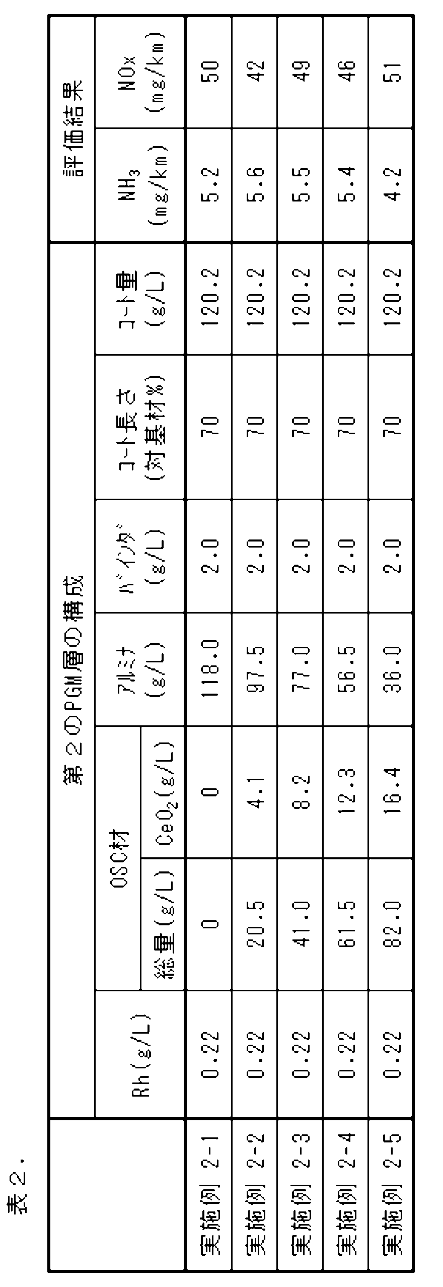
- Examples 2-2 to 2-5 In “(3) Preparation of the coating liquid for forming the second PGM layer", the blending amounts of the OSC material and alumina were changed as shown in Table 2, respectively, and an exhaust gas purification catalyst device was manufactured and evaluated in the same manner as in Example 2-1. The results are shown in Table 2.
Landscapes
- Chemical & Material Sciences (AREA)
- Engineering & Computer Science (AREA)
- Chemical Kinetics & Catalysis (AREA)
- Organic Chemistry (AREA)
- Materials Engineering (AREA)
- Analytical Chemistry (AREA)
- Health & Medical Sciences (AREA)
- Combustion & Propulsion (AREA)
- Toxicology (AREA)
- Mechanical Engineering (AREA)
- General Engineering & Computer Science (AREA)
- Crystallography & Structural Chemistry (AREA)
- Inorganic Chemistry (AREA)
- Biomedical Technology (AREA)
- Environmental & Geological Engineering (AREA)
- General Chemical & Material Sciences (AREA)
- Oil, Petroleum & Natural Gas (AREA)
- Exhaust Gas Treatment By Means Of Catalyst (AREA)
- Catalysts (AREA)
- Solid-Sorbent Or Filter-Aiding Compositions (AREA)
- Exhaust Gas After Treatment (AREA)
Abstract
Description
プロトン型ゼオライトを含有するNH3吸着層と、
Pd、Pt、及びRhから選択される触媒貴金属を含有するPGM層と、
を有する、ガソリンエンジン用排ガス浄化触媒装置であって、
前記NH3吸着層に含まれる前記プロトン型ゼオライトは、平均細孔径が0.60nm以下であり、
前記NH3吸着層は、
前記PGM層よりも前記基材側に配置されており、
前記基材の排ガス流れ上流端から、前記基材の全長よりも短い長さで配置されており、かつ、
前記PGM層は、前記基材の排ガス流れ上流端から、前記NH3吸着層よりも長い長さで配置されており、
前記PGM層が、Pd及びPtから選択される触媒貴金属を含有する第1のPGM層と、Rhを含有する第2のPGM層とを有し、
前記第1のPGM層がセリアを含む、
排ガス浄化触媒装置。
《態様2》前記プロトン型ゼオライトが、基本骨格が4、6、及び8員環から選ばれる環のみから構成されている少員環プロトン型ゼオライトを、前記プロトン型ゼオライトの全質量に対して80質量%以上含む、態様1に記載の排ガス浄化触媒装置。
《態様3》前記少員環プロトン型ゼオライトが、H-ACO、H-AEI、H-AEN、H-AFN、H-AFT、AFX、H-ANA、H-APC、H-APD、H-ATT、H-CDO、H-CHA、H-DDR、H-DFT、H-EAB、H-EDI、H-EPI、H-ERI、H-GIS、H-GOO、H-IHW、H-ITE、H-ITW、H-LEV、H-LTA、H-KFI、H-MER、H-MON、H-NSI、H-OWE、H-PAU、H-PHI、H-RHO、H-RTH、H-SAT、H-SAV、H-SIV、H-THO、H-TSC、H-UEI、H-UFI、H-VNI、H-YUG、及びH-ZONから選択される1種又は2種以上である、態様2に記載の排ガス浄化触媒装置。
《態様4》前記第1のPGM層に含まれるセリアの量が、基材容量1L当たりのセリア質量として、4.0g/L以上45.0g/L以下である、態様1に記載の排ガス浄化触媒装置。
《態様5》前記第1のPGM層に含まれるセリアの量が、基材容量1L当たりのセリア質量として、4.0g/L以上45.0g/L以下である、態様2に記載の排ガス浄化触媒装置。
《態様6》前記第1のPGM層は、前記基材の排ガス流れ上流端から基材全長の10%以上の長さが、排ガスと直接接する最上層となっており、かつ、
前記第2のPGM層は、前記基材の排ガス流れ下流端から基材全長の20%以上の長さが、排ガスと直接接する最上層となっている、
態様1~5のいずれか一項に記載の排ガス浄化触媒装置。
《態様7》前記第1のPGM層が、前記基材の排ガス上流端から基材全長の70%超の長さで配置されている、態様6に記載の排ガス浄化触媒装置。
《態様8》前記第2のPGM層が、前記基材の排ガス下流端から基材全長の20%以上90%以下の長さで配置されている、態様6に記載の排ガス浄化触媒装置。
《態様9》前記第1のPGM層が、前記基材の排ガス上流端から基材全長の70%超の長さで配置されており、
前記第2のPGM層が、前記基材の排ガス下流端から基材全長の30%以上90%以下の長さで配置されており、
前記第1のPGM層の長さと前記第2のPGM層の長さとの合計が前記基材の全長を超え、かつ、
前記第1のPGM層と前記第2のPGM層とが重複している領域では、前記第2のPGM層が排ガスと直接接する最上層となっている、
態様6に記載の排ガス浄化触媒装置。
《態様10》ガソリンエンジンの排気系に、態様1~5のいずれか一項に記載の排ガス浄化触媒装置を配置して、前記ガソリンエンジンから排出された排ガスを浄化することを含む、排ガス浄化方法。
《態様11》ガソリンエンジンの排気系の排ガス流れ上流側に配置された上流側浄化触媒装置と、
前記排気系の排ガス流れ下流側に配置された下流側浄化触媒装置と
を含む、ガソリンエンジン用排ガス浄化触媒システムであって、
前記上流側浄化触媒装置が、白金族の触媒貴金属を含む3元系排ガス浄化触媒装置であり、
前記下流側浄化触媒装置が、態様1~5のいずれか一項に記載の排ガス浄化触媒装置である、
排ガス浄化触媒システム。
《態様12》ガソリンエンジンの排気系に、態様11に記載の排ガス浄化触媒システムを配置して、前記ガソリンエンジンから排出された排ガスを浄化することを含む、排ガス浄化方法
本発明の排ガス浄化触媒装置は、
基材と、
プロトン型ゼオライトを含有するNH3吸着層と、
Pd、Pt、及びRhから選択される触媒貴金属を含有するPGM層と、
を有する、ガソリンエンジン用排ガス浄化触媒装置であって、
前記NH3吸着層に含まれる前記プロトン型ゼオライトは、平均細孔径が0.60nm以下であり、
前記NH3吸着層は、
前記PGM層よりも前記基材側に配置されており、
前記基材の排ガス流れ上流端から、前記基材の全長よりも短い長さで配置されており、かつ、
前記PGM層は、前記基材の排ガス流れ上流端から、前記NH3吸着層よりも長い長さで配置されており、
前記PGM層が、Pd及びPtから選択される触媒貴金属を含有する第1のPGM層と、Rhを含有する第2のPGM層とを有し、
前記第1のPGM層がセリアを含む、
排ガス浄化触媒装置である。
本発明の排ガス浄化触媒装置における基材は、隔壁によって区分された複数のセル流路を有する基材であってよく、従来技術の排ガス浄化触媒装置に用いられているハニカム基材であってよい。基材の隔壁は、隣接する排ガス流路間を流体的に連通する細孔を有していてもよいし、このような細孔を有していなくてもよい。
NH3吸着層は、プロトン型ゼオライトを含有する。
PGM層は、Pd及びPtから選択される触媒貴金属を含有する第1のPGM層と、触媒貴金属としてRhを含有する第2のPGM層とを有し、かつ、第1のPGM層がセリア(CeO2)を含む。
第1のPGM層が、基材の排ガス上流端から基材全長の70%超の長さで配置されており、
第2のPGM層が、基材の排ガス下流端から基材全長の30%以上90%以下の長さで配置されており、
第1のPGM層の長さと第2のPGM層の長さとの合計が基材の全長を超え、かつ、
第1のPGM層と第2のPGM層とが重複している領域では、第2のPGM層が排ガスと直接接する最上層となっている。
本発明の排ガス浄化触媒装置は、上記の構成を有している限り、どのような方法で製造されてもよい。
本発明の別の観点によると、排ガス浄化触媒システムが提供される。
ガソリンエンジンの排気系の排ガス流れ上流側に配置された上流側浄化触媒装置と、
前記排気系の排ガス流れ下流側に配置された下流側浄化触媒装置と
を含む、ガソリンエンジン用排ガス浄化触媒システムであって、
前記上流側浄化触媒装置が、白金族の触媒貴金属を含む3元系排ガス浄化触媒装置であり、
前記下流側浄化触媒装置が、上記に説明した本発明の排ガス浄化触媒装置である。
本発明の更に別の観点によると、排ガス浄化方法が提供される。
ガソリンエンジンの排気系に、本発明の排ガス浄化触媒装置、又は本発明の排ガス浄化触媒システムを配置して、ガソリンエンジンから排出された排ガスを浄化することを含む、排ガス浄化方法である。
塗工液の調製において、アルミナ,OSC材、及びバインダーとしては、それぞれ、下記のものを用いた。
アルミナ:4.0%のLa2O3及び96.0%のAl2O3を含むアルミナ
第1のPGM層形成用塗工液のOSC材:40.0質量%のCeO2、50.0質量%のZrO2、5.0量%のPr2O3、及び5.0質量%のLa2O3を含む複合酸化物
第2のPGM層形成用塗工液のOSC材:21.0質量%のCeO2、72.0質量%のZrO2、5.3量%のNd2O3、及び1.7質量%のLa2O3を含む複合酸化物
バインダー:アルミナバインダー
(1)NH3吸着層形成用塗工液
イオン交換水中に、106.0g/LのH-CHA、7.0g/Lのアルミナバインダー、及び増粘剤としてのセルロース系樹脂を投入し、撹拌することにより、NH3吸着層形成用塗工液を調製した。
イオン交換水中に、Pt金属換算1.1g/L相当の硝酸白金、180.0g/Lのアルミナ、10.0g/LのBaSO4、4.0g/Lのアルミナバインダー、及び増粘剤としてのセルロース系樹脂を投入し、撹拌することにより、第1のPGM層形成用塗工液を調製した。この比較例1-1の第1のPGM層形成用塗工液には、OSC材を配合しなかった。
イオン交換水中に、Rh金属換算0.22g/L相当の硝酸ロジウム、43.0g/LのOSC材(CeO2換算8.6g/L)、75.0g/Lのアルミナ、2.0g/Lのアルミナバインダー、及び増粘剤としてのセルロース系樹脂を投入し、撹拌することにより、第2のPGM層形成用塗工液を調製した。
コージェライト製のストレートフロー型のハニカム基材(直径105.7mm、全長114.3mm、見かけ容量1.003L、セル数400cpsi)の、排ガス流れ上流端から基材全長の75%の範囲にわたって、NH3吸着層形成用塗工液全量を塗布し、90℃において2時間通風乾燥した後、500℃において2時間焼成して、基材上に、コート量113.0g/Lにて、NH3吸着層を形成した。
上記で得られた比較例1-1の排ガス浄化触媒装置は、触媒貴金属としてPd及びRhを含む3元系触媒装置(基材の見かけ容量1.003L)と組み合わせた排ガス浄化触媒システムとして、以下の方法によって評価した。
V型8気筒、排気量4,600ccのガソリンエンジンの排気系の上流側に3元系触媒装置を、下流側に比較例1-1の排ガス浄化触媒装置を配置して、排ガス浄化触媒システムを構成した。そして、エンジンを稼働して、平均エンジン回転数3,000rpm、下流側排ガス浄化触媒装置への入りガス温度を850℃にて、46時間にわたって、排ガス浄化触媒システムに、ストイキ雰囲気及びリーン雰囲気の排ガスを一定時間ずつ交互に流通させることによって、排ガス浄化触媒システムの耐久を行った。
排気量1,500ccのガソリンエンジンを備える実車両のエンジン直下に3元系触媒装置を、床下触媒として、上記の耐久を行った後の比較例1-1の排ガス浄化触媒装置を配置して、排ガス浄化触媒システムを構成した。また、比較例1-1の排ガス浄化触媒装置の出側を、FT-IR装置に接続した。この状態の実車両を、シャシダイナモメータ上でRDE(Real Driving Emission)試験を模した運転モードで運転した。そして、FT-IRによって、比較例1-1の排ガス浄化触媒装置から排出される排ガス中のNH3濃度を測定し、NH3エミッションを求めた。また、市販の自動車排ガス測定器を比較例1-1の排ガス浄化触媒装置の出側に接続して、COエミッション及びTHC(総炭化水素)エミッションを測定した。結果を表1に示す。
「(2)第1のPGM層形成用塗工液の調製」において、OSC材及びアルミナの配合量を、それぞれ、表1に記載のとおりに変更した他は、比較例1-1と同様にして排ガス浄化触媒装置を製造して評価した。結果を表1に示す。

(1)NH3吸着層形成用塗工液
実施例2-1のNH3吸着層形成用塗工液は、比較例1-1のNH3吸着層形成用塗工液と同様にして調製した。
イオン交換水中に、Pt金属換算1.1g/L相当の硝酸白金、45.0g/LのOSC材(CeO2換算18.0g/L)、135.0g/Lのアルミナ、10.0g/LのBaSO4、4.0g/Lのアルミナバインダー、及び増粘剤としてのセルロース系樹脂を投入し、撹拌することにより、第1のPGM層形成用塗工液を調製した。
イオン交換水中に、Rh金属換算0.22g/L相当の硝酸ロジウム、118.0g/Lのアルミナ、2.0g/Lのアルミナバインダー、及び増粘剤としてのセルロース系樹脂を投入し、撹拌することにより、第2のPGM層形成用塗工液を調製した。この実施例2-1の第2のPGM層形成用塗工液には、OSC材を配合しなかった。
「NH3吸着層形成用塗工液」、「第1のPGM層形成用塗工液」、及び「第2のPGM層形成用塗工液」として、それぞれ、上記で調製した各塗工液を用いた他は、比較例1-1と同様にして、排ガス浄化触媒装置を製造した。
上記で得られた実施例2-1の排ガス浄化触媒装置を用いて、比較例1-1と同様にして評価した。結果を表2に示す。
「(3)第2のPGM層形成用塗工液の調製」において、OSC材及びアルミナの配合量を、それぞれ、表2に記載のとおりに変更した他は、実施例2-1と同様にして排ガス浄化触媒装置を製造して評価した。結果を表2に示す。
20 NH3吸着層
30 PGM層
31 第1のPGM層
32 第2のPGM層
100 排ガス浄化触媒装置
Claims (12)
- 基材と、
プロトン型ゼオライトを含有するNH3吸着層と、
Pd、Pt、及びRhから選択される触媒貴金属を含有するPGM層と、
を有する、ガソリンエンジン用排ガス浄化触媒装置であって、
前記NH3吸着層に含まれる前記プロトン型ゼオライトは、平均細孔径が0.60nm以下であり、
前記NH3吸着層は、
前記PGM層よりも前記基材側に配置されており、
前記基材の排ガス流れ上流端から、前記基材の全長よりも短い長さで配置されており、かつ、
前記PGM層は、前記基材の排ガス流れ上流端から、前記NH3吸着層よりも長い長さで配置されており、
前記PGM層が、Pd及びPtから選択される触媒貴金属を含有する第1のPGM層と、Rhを含有する第2のPGM層とを有し、
前記第1のPGM層がセリアを含む、
排ガス浄化触媒装置。 - 前記プロトン型ゼオライトが、基本骨格が4、6、及び8員環から選ばれる環のみから構成されている少員環プロトン型ゼオライトを、前記プロトン型ゼオライトの全質量に対して80質量%以上含む、請求項1に記載の排ガス浄化触媒装置。
- 前記少員環プロトン型ゼオライトが、H-ACO、H-AEI、H-AEN、H-AFN、H-AFT、AFX、H-ANA、H-APC、H-APD、H-ATT、H-CDO、H-CHA、H-DDR、H-DFT、H-EAB、H-EDI、H-EPI、H-ERI、H-GIS、H-GOO、H-IHW、H-ITE、H-ITW、H-LEV、H-LTA、H-KFI、H-MER、H-MON、H-NSI、H-OWE、H-PAU、H-PHI、H-RHO、H-RTH、H-SAT、H-SAV、H-SIV、H-THO、H-TSC、H-UEI、H-UFI、H-VNI、H-YUG、及びH-ZONから選択される1種又は2種以上である、請求項2に記載の排ガス浄化触媒装置。
- 前記第1のPGM層に含まれるセリアの量が、基材容量1L当たりのセリア質量として、4.0g/L以上45.0g/L以下である、請求項1に記載の排ガス浄化触媒装置。
- 前記第1のPGM層に含まれるセリアの量が、基材容量1L当たりのセリア質量として、4.0g/L以上45.0g/L以下である、請求項2に記載の排ガス浄化触媒装置。
- 前記第1のPGM層は、前記基材の排ガス流れ上流端から基材全長の10%以上の長さが、排ガスと直接接する最上層となっており、かつ、
前記第2のPGM層は、前記基材の排ガス流れ下流端から基材全長の20%以上の長さが、排ガスと直接接する最上層となっている、
請求項1~5のいずれか一項に記載の排ガス浄化触媒装置。 - 前記第1のPGM層が、前記基材の排ガス上流端から基材全長の70%超の長さで配置されている、請求項6に記載の排ガス浄化触媒装置。
- 前記第2のPGM層が、前記基材の排ガス下流端から基材全長の20%以上90%以下の長さで配置されている、請求項6に記載の排ガス浄化触媒装置。
- 前記第1のPGM層が、前記基材の排ガス上流端から基材全長の70%超の長さで配置されており、
前記第2のPGM層が、前記基材の排ガス下流端から基材全長の30%以上90%以下の長さで配置されており、
前記第1のPGM層の長さと前記第2のPGM層の長さとの合計が前記基材の全長を超え、かつ、
前記第1のPGM層と前記第2のPGM層とが重複している領域では、前記第2のPGM層が排ガスと直接接する最上層となっている、
請求項6に記載の排ガス浄化触媒装置。 - ガソリンエンジンの排気系に、請求項1~5のいずれか一項に記載の排ガス浄化触媒装置を配置して、前記ガソリンエンジンから排出された排ガスを浄化することを含む、排ガス浄化方法。
- ガソリンエンジンの排気系の排ガス流れ上流側に配置された上流側浄化触媒装置と、
前記排気系の排ガス流れ下流側に配置された下流側浄化触媒装置と
を含む、ガソリンエンジン用排ガス浄化触媒システムであって、
前記上流側浄化触媒装置が、白金族の触媒貴金属を含む3元系排ガス浄化触媒装置であり、
前記下流側浄化触媒装置が、請求項1~5のいずれか一項に記載の排ガス浄化触媒装置である、
排ガス浄化触媒システム。 - ガソリンエンジンの排気系に、請求項11に記載の排ガス浄化触媒システムを配置して、前記ガソリンエンジンから排出された排ガスを浄化することを含む、排ガス浄化方法。
Priority Applications (2)
| Application Number | Priority Date | Filing Date | Title |
|---|---|---|---|
| EP24831535.0A EP4737003A1 (en) | 2023-06-27 | 2024-05-28 | Exhaust gas purification catalyst device for gasoline engine |
| CN202480043394.0A CN121398906A (zh) | 2023-06-27 | 2024-05-28 | 汽油发动机用排气净化催化剂装置 |
Applications Claiming Priority (2)
| Application Number | Priority Date | Filing Date | Title |
|---|---|---|---|
| JP2023-105178 | 2023-06-27 | ||
| JP2023105178A JP7608525B1 (ja) | 2023-06-27 | 2023-06-27 | ガソリンエンジン用排ガス浄化触媒装置 |
Publications (1)
| Publication Number | Publication Date |
|---|---|
| WO2025004664A1 true WO2025004664A1 (ja) | 2025-01-02 |
Family
ID=93938203
Family Applications (1)
| Application Number | Title | Priority Date | Filing Date |
|---|---|---|---|
| PCT/JP2024/019467 Ceased WO2025004664A1 (ja) | 2023-06-27 | 2024-05-28 | ガソリンエンジン用排ガス浄化触媒装置 |
Country Status (4)
| Country | Link |
|---|---|
| EP (1) | EP4737003A1 (ja) |
| JP (1) | JP7608525B1 (ja) |
| CN (1) | CN121398906A (ja) |
| WO (1) | WO2025004664A1 (ja) |
Citations (5)
| Publication number | Priority date | Publication date | Assignee | Title |
|---|---|---|---|---|
| WO2020226127A1 (ja) * | 2019-05-07 | 2020-11-12 | 株式会社キャタラー | アンモニア酸化触媒装置 |
| WO2023058496A1 (ja) * | 2021-10-04 | 2023-04-13 | 株式会社キャタラー | ガソリンエンジン用排ガス浄化システムおよび排ガス浄化用触媒体 |
| JP7288555B1 (ja) * | 2022-02-25 | 2023-06-07 | 株式会社キャタラー | ガソリンエンジンの排ガス浄化用触媒体およびこれを用いた排ガス浄化システム |
| JP7504252B1 (ja) * | 2023-03-14 | 2024-06-21 | 株式会社キャタラー | 排ガス浄化触媒装置及び排ガス浄化触媒システム |
| JP2025039633A (ja) | 2019-04-17 | 2025-03-21 | コンパス パスファインダー リミテッド | サイロシビンによるうつ病及び他の様々な障害の治療 |
-
2023
- 2023-06-27 JP JP2023105178A patent/JP7608525B1/ja active Active
-
2024
- 2024-05-28 CN CN202480043394.0A patent/CN121398906A/zh active Pending
- 2024-05-28 EP EP24831535.0A patent/EP4737003A1/en active Pending
- 2024-05-28 WO PCT/JP2024/019467 patent/WO2025004664A1/ja not_active Ceased
Patent Citations (5)
| Publication number | Priority date | Publication date | Assignee | Title |
|---|---|---|---|---|
| JP2025039633A (ja) | 2019-04-17 | 2025-03-21 | コンパス パスファインダー リミテッド | サイロシビンによるうつ病及び他の様々な障害の治療 |
| WO2020226127A1 (ja) * | 2019-05-07 | 2020-11-12 | 株式会社キャタラー | アンモニア酸化触媒装置 |
| WO2023058496A1 (ja) * | 2021-10-04 | 2023-04-13 | 株式会社キャタラー | ガソリンエンジン用排ガス浄化システムおよび排ガス浄化用触媒体 |
| JP7288555B1 (ja) * | 2022-02-25 | 2023-06-07 | 株式会社キャタラー | ガソリンエンジンの排ガス浄化用触媒体およびこれを用いた排ガス浄化システム |
| JP7504252B1 (ja) * | 2023-03-14 | 2024-06-21 | 株式会社キャタラー | 排ガス浄化触媒装置及び排ガス浄化触媒システム |
Also Published As
| Publication number | Publication date |
|---|---|
| CN121398906A (zh) | 2026-01-23 |
| EP4737003A1 (en) | 2026-05-06 |
| JP2025005134A (ja) | 2025-01-16 |
| JP7608525B1 (ja) | 2025-01-06 |
Similar Documents
| Publication | Publication Date | Title |
|---|---|---|
| JP3855266B2 (ja) | 排気ガス浄化用触媒 | |
| JP5854995B2 (ja) | ガソリンエンジン排ガス処理システム | |
| JP6386449B2 (ja) | ガソリンパーティキュレートフィルタの上流側で使用するための始動時触媒 | |
| CN101069833B (zh) | 烃吸附剂、废气净化用催化剂以及废气净化方法 | |
| CN112916037B (zh) | 包含具有特定粒度分布的金属氧化物载体粒子的催化剂组合物 | |
| WO2007015387A1 (ja) | 排ガス浄化用触媒 | |
| JP6440771B2 (ja) | 排ガス浄化触媒装置 | |
| JP5917516B2 (ja) | Nh3−形成活性が改良された、ガソリンリーンバーンエンジンのための触媒 | |
| WO2007010899A1 (ja) | 排ガス浄化用触媒 | |
| US9446395B2 (en) | Low temperature catalyst/hydrocarbon trap | |
| WO2008004588A1 (en) | Exhaust gas purifying catalyst | |
| WO2012137937A1 (ja) | 排ガス浄化用触媒 | |
| CN103097021B (zh) | 具有降低的Rh载荷的NOx存储催化剂 | |
| EP1468721A1 (en) | Exhaust gas purifying catalyst and process for purifying exhaust gas | |
| EP1482139A1 (en) | Exhaust gas purifying system | |
| CN113631241B (zh) | 排气净化催化剂装置 | |
| EP4393587B1 (en) | Exhaust gas purification system for gasoline engine | |
| JP7504252B1 (ja) | 排ガス浄化触媒装置及び排ガス浄化触媒システム | |
| CN112236228B (zh) | 排气净化催化剂装置 | |
| JP7608525B1 (ja) | ガソリンエンジン用排ガス浄化触媒装置 | |
| JP2003135970A (ja) | 排気ガス浄化用触媒 | |
| CN118785968A (zh) | 汽油发动机排气净化用催化剂体和使用其的排气净化系统 | |
| JPH0999217A (ja) | 排ガス浄化システム | |
| JP7793652B2 (ja) | ガソリンエンジンの排ガス浄化用触媒体およびこれを用いた排ガス浄化システム | |
| JP2002018242A (ja) | エンジンの排気ガス浄化装置 |
Legal Events
| Date | Code | Title | Description |
|---|---|---|---|
| 121 | Ep: the epo has been informed by wipo that ep was designated in this application |
Ref document number: 24831535 Country of ref document: EP Kind code of ref document: A1 |
|
| WWE | Wipo information: entry into national phase |
Ref document number: 202517128095 Country of ref document: IN |
|
| WWP | Wipo information: published in national office |
Ref document number: 202517128095 Country of ref document: IN |
|
| WWE | Wipo information: entry into national phase |
Ref document number: 2024831535 Country of ref document: EP |
|
| NENP | Non-entry into the national phase |
Ref country code: DE |
|
| ENP | Entry into the national phase |
Ref document number: 2024831535 Country of ref document: EP Effective date: 20260127 |
|
| ENP | Entry into the national phase |
Ref document number: 2024831535 Country of ref document: EP Effective date: 20260127 |