WO2025004642A1 - 純水製造システムおよび純水製造方法 - Google Patents
純水製造システムおよび純水製造方法 Download PDFInfo
- Publication number
- WO2025004642A1 WO2025004642A1 PCT/JP2024/019109 JP2024019109W WO2025004642A1 WO 2025004642 A1 WO2025004642 A1 WO 2025004642A1 JP 2024019109 W JP2024019109 W JP 2024019109W WO 2025004642 A1 WO2025004642 A1 WO 2025004642A1
- Authority
- WO
- WIPO (PCT)
- Prior art keywords
- water
- reverse osmosis
- osmosis membrane
- ion exchange
- treated
- Prior art date
- Legal status (The legal status is an assumption and is not a legal conclusion. Google has not performed a legal analysis and makes no representation as to the accuracy of the status listed.)
- Ceased
Links
Images



Classifications
-
- Y—GENERAL TAGGING OF NEW TECHNOLOGICAL DEVELOPMENTS; GENERAL TAGGING OF CROSS-SECTIONAL TECHNOLOGIES SPANNING OVER SEVERAL SECTIONS OF THE IPC; TECHNICAL SUBJECTS COVERED BY FORMER USPC CROSS-REFERENCE ART COLLECTIONS [XRACs] AND DIGESTS
- Y02—TECHNOLOGIES OR APPLICATIONS FOR MITIGATION OR ADAPTATION AGAINST CLIMATE CHANGE
- Y02A—TECHNOLOGIES FOR ADAPTATION TO CLIMATE CHANGE
- Y02A20/00—Water conservation; Efficient water supply; Efficient water use
- Y02A20/124—Water desalination
- Y02A20/131—Reverse-osmosis
Definitions
- the present invention relates to a pure water production system and a method for producing pure water using the same, and in particular to a pure water production system that combines the efficient operating performance of the pure water production equipment with the performance of producing pure water with stable water quality, and a method for producing pure water using the same.
- ultrapure water used in the semiconductor and other electronics industries is produced by treating raw water in an ultrapure water production system that is composed of a pretreatment system, a primary pure water production device (pure water production system), and a subsystem that treats the primary pure water (secondary pure water production device).
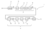
- an ultrapure water production system 1 is composed of three stages of equipment: a pretreatment device 2, a primary pure water production device (pure water production system) 3, and a subsystem 4.
- the pretreatment device 2 of this ultrapure water production system 1 the raw water W is pretreated by filtration, coagulation and sedimentation, and using a microfiltration membrane, and mainly suspended solids are removed.
- the primary pure water production system 3 has a two-stage reverse osmosis membrane device 5, 6 that treats the pretreated water W1, and an electrically regenerative ion exchange device 7, and a relay tank, water pump, or boost pump can be provided between these devices. It also has an ultraviolet oxidation device 8 in the downstream of the electrically regenerative ion exchange device 7. This ultraviolet oxidation device 8 may also be in the upstream of the electrically regenerative ion exchange device 7.
- This primary pure water production system 3 removes most of the electrolytes, fine particles, live bacteria, etc. in the pretreated water W1 and decomposes organic matter to obtain primary pure water (pure water) W2.
- the subsystem 4 has a sub-tank 10, a supply pump 11, an ultraviolet oxidation device 12, a non-regenerative mixed-bed ion exchange device 13, and an ultrafiltration membrane (UF membrane) 14, and is configured to return water from the ultrafiltration membrane (UF membrane) 14 to the sub-tank 10 via a use point 15.
- UF membrane ultrafiltration membrane
- an alkali such as NaOH is injected into the water supplied to the reverse osmosis membrane device 6 to adjust the pH to 8 or higher, promoting the ionization of various components and treating the water.
- the electrical regeneration ion exchange device 7 used in the primary pure water production system 3 generally has cation exchange membranes and anion exchange membranes alternately arranged between a negative electrode (cathode) and an anode (anode), and these cation exchange membranes and anion exchange membranes are used to form compartments to form desalting compartments and concentration compartments, which are then filled with ion exchange resin.
- ion exchange membranes such as cation exchange membranes and anion exchange membranes
- ion exchange membranes include heterogeneous membranes formed by adding a binder such as polystyrene to powdered ion exchange resin, homogeneous membranes formed by polymerization of styrene-divinylbenzene, and membranes formed by graft polymerization of monomers with various anion exchange or cation exchange functions.
- the desalting compartment is filled with a mixture or multiple layers of ion exchangers (anion exchangers and cation exchangers) made of ion exchange resin, ion exchange fibers, graft exchangers, etc.
- ion exchangers anion exchangers and cation exchangers
- the concentration compartment, anode compartment, and cathode compartment are also filled with ion exchangers.
- the permeate water from the reverse osmosis membrane device 6 is used as the water supply for the electrically regenerative ion exchange device, or the permeate water from the reverse osmosis membrane device is treated in an ultraviolet oxidation device and then used as the water supply for the electrically regenerative ion exchange device.
- the reverse osmosis membrane device and the electrical regenerative ion exchange device may be configured such that the water to be treated W4 is treated in a first reverse osmosis membrane device 21, an alkaline chemical is added to the permeated water from an alkali adding means 22 to adjust the pH to 8-11 to produce conditioned water W5, which is then treated in a second reverse osmosis membrane device 23, and the permeated water W6 is treated in an electrical regenerative ion exchange device (CEDI) 24 to obtain treated water W7.
- CEDI electrical regenerative ion exchange device
- a low pressure reverse osmosis membrane (LPRO) is used in at least one of the first reverse osmosis membrane device 21 or the second reverse osmosis membrane device 23. Furthermore, in the electrical regenerative ion exchange device 24, the feed water or treated water for the desalting compartment is used as the concentrated water, and the desalting compartment and the concentrating compartment are passed through in the same direction in all or part of the case.
- LPRO low pressure reverse osmosis membrane
- low-pressure reverse osmosis membranes have a high impurity removal rate, they require an effective membrane surface pressure of 1.0 to 2.0 MPa to achieve an appropriate permeation flow rate, which necessitates large pump power and increases the amount of electricity required for operation.
- the present invention was made in consideration of the above problems, and aims to provide a pure water production system that combines the efficient operating performance of pure water production equipment with the performance of producing pure water with stable water quality, and a pure water production method using the same.
- the present invention first provides a pure water production system having a first ultra-low pressure reverse osmosis membrane device having an effective membrane surface pressure of 0.4 to 0.9 MPa to which water to be treated is supplied, a pH adjustment device that adjusts the pH of the permeate from the first ultra-low pressure reverse osmosis membrane device to 8 to 11, a second ultra-low pressure reverse osmosis membrane device having an effective membrane surface pressure of 0.4 to 0.9 MPa to which conditioned water pH-adjusted by the pH adjustment device is supplied, and an electrical regeneration type ion exchange device to which the permeate from the second ultra-low pressure reverse osmosis membrane device is supplied (Invention 1).
- an ultra-low pressure reverse osmosis membrane device with an effective membrane surface pressure of 0.4 to 0.9 MPa is used as the first-stage reverse osmosis membrane device, so that the water to be treated (raw water to be treated) can be treated with an appropriate flux with lower power consumption than conventional low-pressure reverse osmosis membranes.
- an alkaline chemical is added from a pH adjustment device to adjust the pH of the permeate from the first-stage reverse osmosis membrane device to 8 to 11 to promote ionization of difficult-to-remove components, and then an ultra-low pressure reverse osmosis membrane device with an effective membrane surface pressure of 0.4 to 0.9 MPa is used as the second-stage reverse osmosis membrane device, so that the water to be treated (raw water to be treated) can be treated with an appropriate flux with lower power consumption than conventional low-pressure reverse osmosis membranes. Then, pure water of stable water quality can be produced by treating the permeate from this second-stage reverse osmosis membrane device with an electrically regenerated ion exchange device (CEDI). This allows for a pure water production system that combines efficient operation of the pure water production equipment with the production of pure water with stable water quality.
- CEDI electrically regenerated ion exchange device
- invention 2 when the permeate from the second-stage reverse osmosis membrane device is treated with an electrical regenerative ion exchange device (CEDI), the water supplied to the desalting compartment or treated water (desalted water) is used as the concentrated water of the electrical regenerative ion exchange device, and by passing the water countercurrently through the desalting compartment and the concentrating compartment, the concentration difference between the desalting compartment and the concentrating compartment is mitigated, making it possible to stably produce high-purity pure water.
- CEDI electrical regenerative ion exchange device
- the treated water (demineralized water) from the electrical regenerative ion exchange device is not in a state in which carbon dioxide has dissociated in the water immediately after discharge, but rather the carbon dioxide dissociates and ionizes over time, lowering the resistivity value. Therefore, when measuring the quality of the treated water (demineralized water) from the electrical deionization device with a resistivity meter or conductivity meter, if the measurement is performed after a certain period of time has elapsed, the quality of the demineralized water can be accurately measured, making it possible to appropriately manage the quality of the demineralized water from the electrical deionization device.
- the present invention provides a method for producing pure water, comprising a first reverse osmosis membrane treatment step of treating the water to be treated with a first ultra-low pressure reverse osmosis membrane device having an effective membrane surface pressure of 0.4 to 0.9 MPa, a pH adjustment step of adjusting the pH of the permeate from the first ultra-low pressure reverse osmosis membrane device to 8 to 11, a second reverse osmosis membrane treatment step of treating the pH-adjusted water in the pH adjustment step with a second ultra-low pressure reverse osmosis membrane device having an effective membrane surface pressure of 0.4 to 0.9 MPa, and a deionization step of treating the permeate from the second ultra-low pressure reverse osmosis membrane device with an electrical regeneration ion exchange device to obtain treated water (Invention 4).
- the water to be treated (raw water to be treated) is treated with an appropriate flux with lower power consumption than conventional low-pressure reverse osmosis membranes, and then an alkaline chemical is added from a pH adjustment device to adjust the pH of the permeate from the first stage reverse osmosis membrane device to 8 to 11 to promote ionization of difficult-to-remove components, and then by using an ultra-low pressure reverse osmosis membrane device with an effective membrane surface pressure of 0.4 to 0.9 MPa, the water to be treated (raw water to be treated) is treated with an appropriate flux with lower power consumption than conventional low-pressure reverse osmosis membranes.
- invention 5 when the permeate from the second-stage reverse osmosis membrane device is treated with an electrical regenerative ion exchange device (CEDI), the water supplied to the desalting compartment or the treated water (desalted water) is used as the concentrated water of the electrical regenerative ion exchange device, and the water is passed countercurrently through the desalting compartment and the concentrating compartment.
- CEDI electrical regenerative ion exchange device
- High-purity pure water can be produced stably.
- the treated water (demineralized water) from the electrical regenerative ion exchange device is not in a state in which carbon dioxide has dissociated in the water immediately after discharge, but rather the carbon dioxide dissociates and ionizes over time, lowering the resistivity value. Therefore, when measuring the quality of the treated water (demineralized water) from the electrical deionization device with a resistivity meter or conductivity meter, if the measurement is performed after a certain period of time has elapsed, the quality of the demineralized water can be accurately measured, making it possible to appropriately manage the quality of the demineralized water from the electrical deionization device.
- a two-stage reverse osmosis membrane device is used to alkalize the water treated by the second-stage reverse osmosis membrane.
- Ultra-low pressure reverse osmosis membrane devices with an effective membrane surface pressure of 0.4 to 0.9 MPa are used as the first-stage reverse osmosis membrane device and the second-stage reverse osmosis membrane device.
- CEDI electrically regenerative ion exchange device
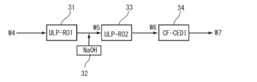
- FIG. 2 is a flow diagram showing the configuration of a two-stage reverse osmosis membrane treatment device and an electrical regeneration type ion exchange device in a pure water production system according to one embodiment of the present invention.
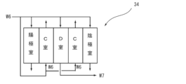
- FIG. 2 is a schematic diagram showing an example of a water flow system of the electrically regenerated ion exchange device in the embodiment.
- FIG. 4 is a schematic diagram showing a method for measuring the resistivity of treated water from an electrically regenerated ion exchange device in the embodiment.
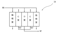
- FIG. 4 is a schematic diagram showing another example of a water flow system of the electrically regenerated ion exchange device in the embodiment.
- FIG. 1 is a flow diagram showing the configuration of a two-stage reverse osmosis membrane treatment device and an electrical regeneration type ion exchange device in a pure water production system according to one embodiment of the present invention.
- FIG. 2 is a schematic diagram showing an example of a water flow system of the electrically regenerated ion exchange device in the embodiment.
- FIG. 4
- FIG. 2 is a flow diagram showing the configuration of a two-stage reverse osmosis membrane treatment device and an electrical regeneration type ion exchange device in the pure water production system used in Example 1.
- 1 is a flow diagram showing an ultrapure water production apparatus to which the pure water production system of the present invention can be applied.
- FIG. 1 is a flow diagram showing the configuration of a two-stage reverse osmosis membrane treatment device and an electrical regeneration type ion exchange device in a conventional pure water production system.
- the pure water producing system of this embodiment may be any system having an electrical regeneration type ion exchange device downstream of a two-stage reverse osmosis membrane device that renders the treated water alkaline through the second-stage reverse osmosis membrane, and can be suitably applied, for example, to the primary pure water producing apparatus 3 in the ultrapure water producing system 1 shown in FIG. 5 described above.
- the two-stage reverse osmosis membrane device has a first reverse osmosis membrane device (ULP-RO1) 31 that treats water W4, an alkali addition means 32 that acts as a pH adjustment device and adds an alkaline chemical to the treated water (permeate) from this first reverse osmosis membrane device 31, a second reverse osmosis membrane device (ULP-RO2) 33 that treats conditioned water W5 whose pH has been adjusted to 8-11 by adding an alkaline chemical, and an electrically regenerated ion exchange device (CEDI) 34 that treats treated water (permeate) W6 from this second reverse osmosis membrane device 33 to produce treated water W7.
- URP-RO1 first reverse osmosis membrane device
- an alkali addition means 32 that acts as a pH adjustment device and adds an alkaline chemical to the treated water (permeate) from this first reverse osmosis membrane device 31
- a second reverse osmosis membrane device (ULP-RO2) 33 that treats
- the ultra-low pressure reverse osmosis membrane is used as each of the first reverse osmosis membrane device 31 and the second reverse osmosis membrane device 33.
- the ultra-low pressure reverse osmosis membrane is a reverse osmosis membrane having a permeation flux of 0.4 to 0.9 m3/( m2 ⁇ day) at an effective membrane surface pressure (water temperature 25°C, pure water (RO permeate)) of 0.4 to 0.9 MPa, a NaCl removal rate of 90% or more, and a boron removal rate of 30% or more.
- the low-pressure reverse osmosis membrane is a reverse osmosis membrane having a permeation flux of 0.3 to 1.0 m 3 /(m 2 ⁇ day) at an effective membrane surface pressure of 1.0 to 2.0 MPa, a NaCl rejection rate of 99% or more, and a boron rejection rate of 50% or more.
- the electrical regeneration ion exchange device is configured such that cation exchange membranes and anion exchange membranes are alternately arranged between a cathode and an anode, and these cation exchange membranes form compartments to form a deionization compartment (compartment D) and a concentration compartment (compartment C) as well as an anode compartment and a cathode compartment at both ends, as shown in Fig. 2.
- Water for the deionization compartment permeated water W6 from the second reverse osmosis membrane device 33
- the permeated water W6 is supplied to the concentration compartment (compartment C) in the opposite direction (countercurrent) to the deionization compartment (compartment D).
- a water supply pump (not shown) is driven to supply the water to be treated W4 to the first reverse osmosis membrane device 31.
- the first reverse osmosis membrane device 31 can treat the water with an appropriate flux and with lower power consumption than conventional low-pressure reverse osmosis membranes.
- pH adjustment step NaOH solution is added to the permeate from the first reverse osmosis membrane device 31 from the alkali adding means 32 to adjust the pH of the permeate from the first reverse osmosis membrane device 31 to 8 to 11, and components that are difficult to ionize, such as silica and carbon dioxide, are ionized.
- the conditioned water W5 whose pH has been adjusted to 8 to 11, is treated in the second reverse osmosis membrane device 33.
- the second reverse osmosis membrane device 33 passes water through an ultra-low pressure reverse osmosis membrane device with an effective membrane surface pressure of 0.4 to 0.9 MPa, it can treat the water with an appropriate flux and with lower power consumption than conventional low-pressure reverse osmosis membranes.
- the permeate W6 from the second reverse osmosis membrane device 33 is treated with an electrically regenerative ion exchange device (CEDI) 34 to remove trace amounts of ionic impurities contained in the permeate W6, thereby obtaining treated water W7.
- CEDI electrically regenerative ion exchange device
- the water flows in the opposite directions (countercurrent) through the desalting compartment and the concentrating compartment of the electrically regenerated ion exchange device 34, which reduces the difference in impurity concentration between the desalting compartment and the concentrating compartment, making it possible to stably produce high-purity pure water.
- highly pure water with a resistivity of 17 M ⁇ cm or more for treated water W7 of the electrically regenerated ion exchange device can be produced with less electricity.
- the resistivity of the desalted water (treated water) W7 of this electrically regenerative ion exchange device 34 is preferably measured, for example, by a method such as that shown in Figure 3.
- branch pipes 41A-41D that supply permeate water W6 from the second reverse osmosis membrane device 33 to the desalting compartments of the electrically regenerative ion exchange devices 34A-34D branched off from a water supply pipe 41 are connected to the multiple (four) series of electrically regenerative ion exchange devices 34A, 34B, 34C, 34D, and outlet pipes 42A-42D for the treated water (desalted water) W7 are connected to the outlets of the desalting compartments.
- These outlet pipes 42A-42D join at a junction pipe 42 to supply treated water W7 to a downstream system.
- Resistivity meters 43A to 43D are provided in the outflow pipes 42A to 42D, respectively, and these resistivity meters 43A to 43D measure the resistivity of the treated water (desalinated water) W7 immediately after it is discharged from the desalting chambers of the electrically regenerative ion exchange devices 34A to 34D, thereby monitoring the quality of the treated water.
- a resistivity meter 43 is also provided in the junction pipe 42.
- the outlet pipes 42A-42D and the junction pipe 42 are made of pipe material made of a hard resin material with gas barrier properties such as polypropylene (PP) or polyvinyl chloride (PVD), or a metal pipe material, preferably all the way up to the connection points of the resistivity meters 43A-43D.
- gas barrier properties such as polypropylene (PP) or polyvinyl chloride (PVD)
- metal pipe material preferably all the way up to the connection points of the resistivity meters 43A-43D.
- the water sampling tubes 44A-44D of the resistivity meters 43A-43D are made of a gas barrier material such as perfluoroalkoxyalkane (PFA) or nylon, and their length is preferably such that the desalted water (treated water) W7 discharged from the outlet of the desalting chamber of the electrically regenerated ion exchange device 34A-34D requires a residence time of 10 seconds or more, and particularly 30 seconds or more, before it reaches the measuring section of the resistivity meters 43A-43D.
- a length of less than 10 seconds until the desalted water (treated water) reaches the measuring section is not preferable because the resistivity will be measured when almost no carbon dioxide in the desalted water (treated water) has been dissociated.
- the length of the water sampling tubes 44A-44D may be set to the desired residence time depending on the tube diameter and water flow rate of the water sampling tube.
- the reason for this configuration is as follows. That is, when the permeate W6 from the second reverse osmosis membrane device 33 is supplied to the desalting chamber of the electrical regenerative ion exchange devices 34A-34D, ionic impurities are removed and treated water (desalted water) W7 is discharged. At this time, the undissociated carbon dioxide in the water to be treated (supply water) W7 is not ionized immediately after it leaves the desalting chamber, so it does not affect the resistivity value. However, the carbon dioxide dissociates and ions over time, decreasing the resistivity value of the treated water (desalted water) W7.
- the length of the water sampling tubes 34A-34D to a length that allows the desalted water (treated water) to remain in the desalted water (treated water) for 10 seconds or more, preferably 30 seconds or more, from the outlet of the desalting chamber until it reaches the measuring section of the resistivity meters 43A-43D, the carbonate ion concentration of the desalted water (treated water) can be measured with high accuracy. If it takes less than 10 seconds for the water to reach the measuring section, the carbonate ion concentration of the desalted water (treated water) cannot be measured accurately, which is not preferable.
- the resistivity of the treated water W7 that joins at the joining section 42 can be measured with a resistivity meter 43 to confirm the resistivity value.
- the quality of the treated water W7 can be maintained at a suitable level. Furthermore, the performance of the electrically regenerated ion exchange device can be accurately grasped, and it is possible to judge not only the suitability of the operating conditions of the electrically regenerated ion exchange device, but also its deterioration and lifespan. It is also possible to accurately grasp the load on downstream equipment and reflect this in the design.
- the electrically regenerated ion exchange device 34 may be configured to pass treated water W7 in the opposite direction (counterflow) between the desalting compartment and the concentrating compartment as shown in FIG. 4.
- the length of the resistivity meter's water sampling tube is adjusted, and the installation position of the resistivity meter is adjusted, but this is not limited to this.
- a retention section for desalted water may be provided in the outlet pipes 42A to 42D, and the resistivity of the desalted water may be measured by the resistivity meter after retention for 10 seconds or more, preferably 30 seconds or more.
- a conductivity meter may be provided instead of the resistivity meter, and the quality of the desalted water from the electrically regenerated ion exchange device may be similarly managed by conductivity instead of resistivity.
- the pure water production system 1 has a structure in which a raw water tank 52, a first feed water pump (RO1 feed water pump) 53, a first reverse osmosis membrane (RO1) 54, a tank 55 for permeated water of the first reverse osmosis membrane 54, an alkali adding means 56 using a NaOH solution, a second feed water pump (RO2 feed water pump) 57, a second reverse osmosis membrane (RO2) 58, an electrical regenerative ion exchange device (CEDI) 59, and a treated water tank 60 for desalted water (treated water) W7 of the electrical regenerative ion exchange device 59 are sequentially provided.
- a raw water tank 52 a first feed water pump (RO1 feed water pump) 53, a first reverse osmosis membrane (RO1) 54, a tank 55 for permeated water of the first reverse osmosis membrane 54, an alkali adding means 56 using a NaOH solution, a second feed water pump (RO2 feed water
- RO membrane reverse osmosis membrane
- RO membrane ultra-low pressure reverse osmosis membrane
- reverse osmosis membrane As the reverse osmosis membrane (RO membrane), an ultra-low pressure reverse osmosis membrane and a reverse osmosis membrane were used. The performance and operating conditions of these are shown below.
- Ultra-low pressure reverse osmosis membrane effective membrane surface pressure of 0.5 to 0.8 MPa, permeate volume of 0.5 to 0.8 m 3 /(m 2 ⁇ day), and water recovery rate of 83 to 87%
- Low-pressure reverse osmosis membrane effective membrane surface pressure 1.2-1.5 MPa, permeate volume 0.5-0.8 m 3 /(m 2 ⁇ day), and water recovery rate 83-87%
- Examples 1 to 3, Comparative Examples 1 to 5 Raw water (water to be treated) W4 containing Na ions, carbonate ions, and boron (B) 10 to 20 ⁇ g/L and having an electrical conductivity of about 20 mS/m was prepared.
- the raw water W4 was supplied from a raw water tank 52 to a first reverse osmosis membrane (RO1) 54 by a first feed water pump (RO1 feed water pump) 53, and the treated water (permeated water) of the first reverse osmosis membrane 54 was received in a tank 55.
- RO1 feed water pump RO1 feed water pump
- the permeated water of the first reverse osmosis membrane 54 was supplied to a second reverse osmosis membrane (RO2) 58 by a second feed water pump (RO2 feed water pump) 57, and at this time, NaOH solution was added to the permeated water of the first reverse osmosis membrane 54 from an alkali addition means 56 as necessary to obtain adjusted water W5.
- This adjusted water W5 was treated with a second reverse osmosis membrane (RO2) 58 to obtain permeated water W6 of the second reverse osmosis membrane.
- This permeate W6 was treated in an electrically regenerated ion exchanger (CEDI) 59 to obtain treated water W7.
- CEDI electrically regenerated ion exchanger
- the water supply rate of the first feed water pump 53 was about 14 m 3 /h
- the water recovery rate of the first reverse osmosis membrane 54 was 83 to 87%
- the water supply rate of the second feed water pump 57 was about 12 m 3 /h
- the water recovery rate of the second reverse osmosis membrane 58 was 88 to 92%.
- the permeated water W6 of the second reverse osmosis membrane 58 was directly supplied to the electrical regenerative ion exchange device 59, which was operated at a constant current of 10 A with a water recovery rate of 93 to 97%, and the voltage fluctuated between 100 and 150 V.
- the amount of treated water W7 of the electrical regenerative ion exchange device 59 was about 10 m 3 /h in both cases.
- the water flow method was switched between parallel flow, in which the water flow direction to the desalting compartment is the same as that to the concentration compartment, and countercurrent flow, in which the water flows in the opposite directions, depending on the conditions.
- the water supply to the concentration compartment was switched between passing the permeate W6 of the second reverse osmosis membrane 58, which is the same as the water supply to the desalting compartment of the electrically regenerated ion exchange device 59, and passing the treated water W7 of the electrically regenerated ion exchange device 59, depending on the conditions.
- Comparative Examples 3 and 5 in which a low pressure reverse osmosis membrane was used as the first reverse osmosis membrane 54 and an ultra-low pressure reverse osmosis membrane was used as the second reverse osmosis membrane 58, treated water with high purity was obtained, but the power consumption was increased by about 40% compared to Examples 1 to 3. Furthermore, in Comparative Examples 1 and 3 in which the water flow method of the electric regenerator ion exchange device 59 was a parallel flow type, the resistivity value after 30 seconds had passed from the outlet of the desalting compartment of the electric regenerator ion exchange device 59 further decreased. This is thought to be because molecular CO 2 present in the treated water W7 of the electric regenerator ion exchange device 59 dissociated over time, lowering the resistivity value.
- Ultrapure water production system 2 Pretreatment device 3 Primary pure water production device (pure water production system) 4 Subsystem 5, 6 Reverse osmosis membrane device 7 Electrically regenerated ion exchange device 8 Ultraviolet oxidation device 10 Subtank 11 Supply pump 12 Ultraviolet oxidation device 13 Non-regenerative mixed bed ion exchange device 14 Ultrafiltration membrane (UF membrane) 15 Point of use 21 First reverse osmosis membrane device 22 Alkali adding means (pH adjusting device) 23 Second reverse osmosis membrane device 24 Electrically regenerative ion exchange device 31 First reverse osmosis membrane device 32 Alkali adding means 33 Second reverse osmosis membrane device 34, 34A to 34D Electrically regenerative ion exchange device 41 Water supply pipes 41A to 41D Branch pipe 42 Junction pipes 42A to 42D Outlet pipes 43, 43A to 43D Resistivity meters 44A to 44D Water sampling tube 51 Pure water production device (pure water production system) 52 raw water tank 53 first feed water pump 54 first reverse osmosis membrane
Landscapes
- Water Supply & Treatment (AREA)
- Engineering & Computer Science (AREA)
- Chemical & Material Sciences (AREA)
- Chemical Kinetics & Catalysis (AREA)
- Separation Using Semi-Permeable Membranes (AREA)
- Life Sciences & Earth Sciences (AREA)
- Organic Chemistry (AREA)
- Environmental & Geological Engineering (AREA)
- Hydrology & Water Resources (AREA)
- Health & Medical Sciences (AREA)
- Urology & Nephrology (AREA)
- Treatment Of Water By Ion Exchange (AREA)
- Water Treatment By Electricity Or Magnetism (AREA)
- Nanotechnology (AREA)
- Analytical Chemistry (AREA)
- Molecular Biology (AREA)
- Electrochemistry (AREA)
- General Chemical & Material Sciences (AREA)
Abstract
純水製造システムは、2段目の逆浸透膜の被処理水をアルカリ性とする2段逆浸透膜装置の後段に電気再生式イオン交換装置を備える。2段逆浸透膜装置は、被処理水W4を第一の逆浸透膜装置31と、この透過水にアルカリ性の薬品を添加してpHを8~11に調整した調整水W5とするアルカリ添加手段32と、この調整水W5を処理する第二の逆浸透膜装置33と、この第二の逆浸透膜装置33の透過水W6を処理して処理水W7を製造する電気再生式イオン交換装置34とを有する。第一の逆浸透膜装置31及び第二の逆浸透膜装置33は、それぞれ超低圧型逆浸透膜を用いたものである。電気再生式イオン交換装置は、第二の逆浸透膜装置33の透過水W6を濃縮室、陽極室及び陰極室に供給する。そして、濃縮室には、脱塩室と向流式で透過水W6を供給する構造となっている。このような純水製造システムであれば、効率的な純水製造設備の運転と、安定した水質の純水製造とを兼ね備えたものとすることができる。
Description
本発明は、純水製造システムおよびこれを用いた純水製造方法に関し、特に効率的な純水製造設備の運転性能と、安定した水質の純水製造性能とを兼ね備えた純水製造システムおよびこれを用いた純水製造方法に関する。
従来、半導体等の電子産業分野で用いられている超純水は、前処理システム、一次純水製造装置(純水製造システム)及び一次純水を処理するサブシステム(二次純水製造装置)で構成される超純水製造システムで原水を処理することにより製造されている。
例えば、図6に示すように超純水製造システム1は、前処理装置2と一次純水製造装置(純水製造システム)3とサブシステム4といった3段の装置で構成されている。このような超純水製造システム1の前処理装置2では、原水Wの濾過、凝集沈殿、精密濾過膜などによる前処理が施され、主に懸濁物質が除去される。
一次純水製造装置3は、前処理水W1を処理する2段構成の逆浸透膜装置5,6と、電気再生式イオン交換装置7とを有し、これらの機器の間に中継槽、送水ポンプまたは昇圧ポンプを設けることができる。さらに電気再生式イオン交換装置7の後段に紫外線酸化装置8を有する。この紫外線酸化装置8は、電気再生式イオン交換装置7の前段としてもよい。この一次純水製造装置3で前処理水W1中の大半の電解質、微粒子、生菌等の除去を行うとともに有機物を分解して、一次純水(純水)W2を得る。
そして、サブシステム4は、サブタンク10と供給ポンプ11と紫外線酸化装置12と非再生型混床式イオン交換装置13と限外ろ過膜(UF膜)14とを有し、限外ろ過膜(UF膜)14からユースポイント15を経由してサブタンク10に還流する構成となっている。このサブシステム4では、一次純水製造装置3で製造された一次純水W2中に含まれる微量の有機物(TOC成分)を酸化分解し、炭酸イオン、有機酸類、アニオン性物質、さらには金属イオンやカチオン性物質をイオン交換体を充填した機器で除去し、最後に限外濾過(UF)膜14で微粒子を除去して超純水W3とし、これをユースポイント15に供給して、未使用の超純水W3はサブタンク10に還流する。
上述したような超純水製造システム1の一次純水製造装置3では、逆浸透膜装置6におけるホウ素の濃度低減などの処理性能向上を目的に、逆浸透膜装置6の給水にNaOH等のアルカリを注入してpH8以上とし、各種成分のイオン化を促進して処理することが行われている。
また、この一次純水製造装置3に用いられる電気再生式イオン交換装置7は、一般に陰極(カソード)及び陽極(アノード)間にカチオン交換膜とアニオン交換膜とを交互に配置し、これらカチオン交換膜及びアニオン交換膜により区画を構成することで脱塩室及び濃縮室を形成し、この脱塩室及び前記濃縮室にイオン交換樹脂を充填したものである。カチオン交換膜やアニオン交換膜などのイオン交換膜としては、粉末状のイオン交換樹脂にポリスチレンなどの結合剤を加えて製膜した不均質膜や、スチレン-ジビニルベンゼン等の重合によって製膜した均質膜などのほか、各種アニオン交換機能あるいはカチオン交換機能を有する単量体をグラフト重合により製膜したものなどが用いられている。
また、脱塩室には、イオン交換樹脂、イオン交換繊維もしくはグラフト交換体等からなるイオン交換体(アニオン交換体及びカチオン交換体)が混合もしくは複層状に充填されている。また、濃縮室と、陽極室及び陰極室にも、イオン交換体が充填されている。
この純水製造システムを構成する電気再生式イオン交換装置では、逆浸透膜装置6の透過水を電気再生式イオン交換装置の給水とする、あるいは逆浸透膜装置の透過水を紫外線酸化装置で処理した後電気再生式イオン交換装置の給水とすることが行われている。
さらに、逆浸透膜装置と電気再生式イオン交換装置とは、図7に示すように被処理水W4を第一の逆浸透膜装置21で処理し、この透過水にアルカリ添加手段22からアルカリ性の薬品を添加してpHを8~11に調整した調整水W5を第二の逆浸透膜装置23で処理し、この透過水W6を電気再生式イオン交換装置(CEDI)24で処理して処理水W7を得る装置もある。このような装置では、第一の逆浸透膜装置21または第二の逆浸透膜装置23の少なくともいずれかに低圧逆浸透膜(LPRO)を用いている。また、電気再生式イオン交換装置24では、濃縮水として、脱塩室の給水または処理水を用い、脱塩室と濃縮室が、すべてまたは一部において同じ方向で通水されている。
しかしながら、低圧逆浸透膜(低圧RO)は不純物の除去率が高い一方で、適切な透過流速を得るための膜面有効圧が1.0~2.0MPa必要であり、ポンプ動力を大きくする必要があり、運転に必要な電力量が大きくなる、という問題点があった。
本発明は、上記課題に鑑みてなされたものであり、効率的な純水製造設備の運転性能と、安定した水質の純水製造性能とを兼ね備えた純水製造システムおよびこれを用いた純水製造方法を提供することを目的とする。
上記目的に鑑み本発明は第一に、被処理水が供給される膜面有効圧が0.4~0.9MPaの第一の超低圧型逆浸透膜装置と、前記第一の超低圧型逆浸透膜装置の透過水のpHを8~11に調整するpH調整装置と、前記pH調整装置によってpH調整された調整水が供給される膜面有効圧が0.4~0.9MPaの第二の超低圧型逆浸透膜装置と、前記第二の超低圧型逆浸透膜装置からの透過水が供給される電気再生式イオン交換装置とを有する純水製造システムを提供する(発明1)。
かかる発明(発明1)によれば、2段目の逆浸透膜の被処理水をアルカリ性とする2段逆浸透膜装置を備えた純水製造システムにおいて、1段目の逆浸透膜装置として膜面有効圧が0.4~0.9MPaの超低圧型逆浸透膜装置を用いることで、被処理水(処理原水)を従来の低圧逆浸透膜よりも低い消費電力で適切なフラックス(Flux)で処理することができる。その後、pH調整装置からアルカリ性の薬品を添加して1段目の逆浸透膜装置の透過水のpHを8~11に調整して難除去成分のイオン化を促進した後、2段目の逆浸透膜装置として膜面有効圧が0.4~0.9MPaの超低圧型逆浸透膜装置を用いることで、被処理水(処理原水)を従来の低圧逆浸透膜よりも低い消費電力で適切なフラックス(Flux)で処理することができる。そして、この2段目の逆浸透膜装置の透過水を電気再生式イオン交換装置(CEDI)で処理することにより、安定した水質の純水を製造することができる。これらにより、効率的な純水製造設備の運転と、安定した水質の純水の製造とを兼ね備えた純水製造システムとすることができる。
上記発明(発明1)においては、前記電気再生式イオン交換装置の脱塩室の通水方向と向流となるように濃縮室を通水し、該濃縮室に電気再生式イオン交換装置の給水または処理水を通水することが好ましい(発明2)。
かかる発明(発明2)によれば、2段目の逆浸透膜装置の透過水を電気再生式イオン交換装置(CEDI)で処理する際に、該電気再生式イオン交換装置の濃縮水として脱塩室への給水または処理水(脱塩水)を用い、脱塩室と濃縮室を向流に通水することで、脱塩室と濃縮室の間の濃度差が緩和されるので、高純度の純水を安定して製造することができる。
上記発明(発明1又は2)においては、前記電気再生式イオン交換装置の脱塩室から吐出された後10秒以上経過した処理水の比抵抗値又は導電率を測定する比抵抗計又は導電率計を有することが好ましい(発明3)。
上記発明(発明3)によれば、電気再生式イオン交換装置の処理水(脱塩水)は、吐出直後は炭酸が水中で乖離した状態ではなく、時間の経過とともに炭酸が乖離してイオン化することで比抵抗値を低下させるので、電気脱イオン装置の処理水(脱塩水)の水質を比抵抗計や導電率計で測定する際に一定時間を経過させた後に測定すれば、脱塩水の水質を的確に計測することができるので、電気脱イオン装置の脱塩水の水質を好適に管理することが可能となる。
また、本発明は第二に、被処理水を膜面有効圧が0.4~0.9MPaの第一の超低圧型逆浸透膜装置で処理する第一の逆浸透膜処理工程と、前記第一の超低圧型逆浸透膜装置の透過水のpHを8~11に調整するpH調整工程と、このpH調整工程によってpH調整された調整水を膜面有効圧が0.4~0.9MPaの第二の超低圧型逆浸透膜装置で処理する第二の逆浸透膜処理工程と、前記第二の超低圧型逆浸透膜装置の透過水を電気再生式イオン交換装置で処理する処理水を得る脱イオン工程とを有する純水製造方法を提供する(発明4)。
かかる発明(発明4)によれば、膜面有効圧が0.4~0.9MPaの超低圧型逆浸透膜装置を用いることで、被処理水(処理原水)を従来の低圧逆浸透膜よりも低い消費電力で適切なフラックス(Flux)で処理し、次に、pH調整装置からアルカリ性の薬品を添加して1段目の逆浸透膜装置の透過水のpHを8~11に調整して難除去成分のイオン化を促進した後、膜面有効圧が0.4~0.9MPaの超低圧型逆浸透膜装置を用いることで、被処理水(処理原水)を従来の低圧逆浸透膜よりも低い消費電力で適切なフラックス(Flux)で処理する。そして、この2段目の逆浸透膜装置の透過水を電気再生式イオン交換装置(CEDI)で処理することにより、純水を安定して製造することができる。これらにより、効率的な純水製造設備の運転と、安定した水質とを両立させて純水を製造することができる。
上記発明(発明4)においては、前記脱イオン工程において、前記電気再生式イオン交換装置の脱塩室の通水方向と向流となるように濃縮室を通水し、該濃縮室に電気再生式イオン交換装置の給水または処理水を通水することが好ましい(発明5)。
かかる発明(発明5)によれば、2段目の逆浸透膜装置の透過水を電気再生式イオン交換装置(CEDI)で処理する際に、該電気再生式イオン交換装置の濃縮水として脱塩室への給水または処理水(脱塩水)を用い、脱塩室と濃縮室を向流に通水することで、脱塩室と濃縮室の間の濃度差が緩和されるので、高純度の純水を安定して製造することができる。
高純度の純水を安定して製造することができる。
高純度の純水を安定して製造することができる。
上記発明(発明4又は5)においては、前記脱イオン工程で得られた処理水の比抵抗値を、該処理水が前記電気再生式イオン交換装置の脱塩室から吐出されて10秒以上経過した後測定し、この測定した比抵抗値が15MΩ・cm以上となるように前記電気再生式イオン交換装置の運転条件を制御することが好ましい(発明6)。
上記発明(発明6)によれば、電気再生式イオン交換装置の処理水(脱塩水)は、吐出直後は炭酸が水中で乖離した状態ではなく、時間の経過とともに炭酸が乖離してイオン化することで比抵抗値を低下させるので、電気脱イオン装置の処理水(脱塩水)の水質を比抵抗計や導電率計で測定する際に一定時間を経過させた後に測定すれば、脱塩水の水質を的確に計測することができるので、電気脱イオン装置の脱塩水の水質を好適に管理することが可能となる。
本発明の純水製造システムによれば、2段目の逆浸透膜の被処理水をアルカリ性とする2段逆浸透膜装置を備えた純水製造システムにおいて、1段目の逆浸透膜装置及び2段目の逆浸透膜装置として、膜面有効圧が0.4~0.9MPaの超低圧型逆浸透膜装置を用いているので、この2段目の逆浸透膜装置の透過水を電気再生式イオン交換装置(CEDI)で処理することにより、効率的な純水製造設備の運転と、安定した水質の純水の製造とをバランスを良く兼ね備えたものとなっている。これにより、例えば、電気再生式イオン交換装置の処理水において、17MΩ・cm以上の比抵抗値の高い純度の純水をより少ない電力で製造することができる。
以下、本発明の純水製造システムについて添付図面を参照して説明する。
〔純水製造システム〕
本実施形態の純水製造システムは、2段目の逆浸透膜の被処理水をアルカリ性とする2段逆浸透膜装置の後段に電気再生式イオン交換装置を有するものであればよく、例えば前述した図5に示す超純水製造システム1における一次純水製造装置3に好適適用することができる。
本実施形態の純水製造システムは、2段目の逆浸透膜の被処理水をアルカリ性とする2段逆浸透膜装置の後段に電気再生式イオン交換装置を有するものであればよく、例えば前述した図5に示す超純水製造システム1における一次純水製造装置3に好適適用することができる。
具体的には、2段逆浸透膜装置は、図1に示すように被処理水W4を第一の逆浸透膜装置(ULP-RO1)31と、この第一の逆浸透膜装置31の処理水(透過水)にアルカリ性の薬品を添加するpH調整装置としてのアルカリ添加手段32と、アルカリ性の薬品の添加によりpHを8~11に調整した調整水W5を処理する第二の逆浸透膜装置(ULP-RO2)33と、この第二の逆浸透膜装置33の処理水(透過水)W6を処理して処理水W7を製造する電気再生式イオン交換装置(CEDI)34とを有する。
(逆浸透膜)
第一の逆浸透膜装置31及び第二の逆浸透膜装置33としては、それぞれ超低圧型逆浸透膜を用いる。本実施形態において、超低圧型逆浸透膜は、膜面有効圧(水温25℃、純水(RO透過水))が0.4~0.9MPaにおける透過流束(フラックス)0.4~0.9m3/(m2・日)、NaCl除去率90%以上、ホウ素除去率30%以上の性能を有する逆浸透膜である。
第一の逆浸透膜装置31及び第二の逆浸透膜装置33としては、それぞれ超低圧型逆浸透膜を用いる。本実施形態において、超低圧型逆浸透膜は、膜面有効圧(水温25℃、純水(RO透過水))が0.4~0.9MPaにおける透過流束(フラックス)0.4~0.9m3/(m2・日)、NaCl除去率90%以上、ホウ素除去率30%以上の性能を有する逆浸透膜である。
膜面有効圧が0.9MPaを超える低圧逆浸透膜では、得られる純水の純度は向上するものの、消費電力が増加する。一方、膜面有効圧が0.4MPa未満の逆浸透膜では、得られる純水の水質が低下する。
なお。低圧型逆浸透膜は、膜面有効圧が1.0~2.0MPaにおける透過流束(フラックス)0.3~1.0m3/(m2・日)、NaCl除去率99%以上、ホウ素除去率50%以上の性能を有する逆浸透膜である。
(電気再生式イオン交換装置)
本実施形態において、電気再生式イオン交換装置としては、陰極(カソード)及び陽極(アノード)間にカチオン交換膜とアニオン交換膜とを交互に配置し、これらカチオン交換膜及びアニオン交換膜により区画を構成することで、図2に示すように脱塩室(D室)及び濃縮室(C室)を形成するとともに両端部に陽極室及び陰極室を形成したものであり、脱塩室の給水(第二の逆浸透膜装置33の透過水W6)を濃縮室(C室)、陽極室及び陰極室に供給する。そして、濃縮室(C室)には脱塩室(D室)と反対方向(向流式)で透過水W6を供給する構造となっている。
本実施形態において、電気再生式イオン交換装置としては、陰極(カソード)及び陽極(アノード)間にカチオン交換膜とアニオン交換膜とを交互に配置し、これらカチオン交換膜及びアニオン交換膜により区画を構成することで、図2に示すように脱塩室(D室)及び濃縮室(C室)を形成するとともに両端部に陽極室及び陰極室を形成したものであり、脱塩室の給水(第二の逆浸透膜装置33の透過水W6)を濃縮室(C室)、陽極室及び陰極室に供給する。そして、濃縮室(C室)には脱塩室(D室)と反対方向(向流式)で透過水W6を供給する構造となっている。
〔純水製造方法〕
上述したような純水製造システムの運転方法について以下説明する。
上述したような純水製造システムの運転方法について以下説明する。
(第一の逆浸透膜処理工程)
まず、図示しない給水ポンプを駆動して被処理水W4を第一の逆浸透膜装置31に供給する。この第一の逆浸透膜装置31は、膜面有効圧が0.4~0.9MPaで超低圧型逆浸透膜装置に通水すると、従来の低圧逆浸透膜よりも低い消費電力で適切なフラックス(Flux)で処理することができる。
まず、図示しない給水ポンプを駆動して被処理水W4を第一の逆浸透膜装置31に供給する。この第一の逆浸透膜装置31は、膜面有効圧が0.4~0.9MPaで超低圧型逆浸透膜装置に通水すると、従来の低圧逆浸透膜よりも低い消費電力で適切なフラックス(Flux)で処理することができる。
(pH調整工程)
次に、第一の逆浸透膜装置31の透過水にアルカリ添加手段32からNaOH溶液を添加して、第一の逆浸透膜装置31の透過水のpHを8~11に調整し、シリカ、炭酸などの難イオン化成分をイオン化する。
次に、第一の逆浸透膜装置31の透過水にアルカリ添加手段32からNaOH溶液を添加して、第一の逆浸透膜装置31の透過水のpHを8~11に調整し、シリカ、炭酸などの難イオン化成分をイオン化する。
(第二の逆浸透膜処理工程)
続いて、このpHを8~11に調整した調整水W5を第二の逆浸透膜装置33で処理する。この第二の逆浸透膜装置33は、膜面有効圧が0.4~0.9MPaで超低圧型逆浸透膜装置に通水すると、従来の低圧逆浸透膜よりも低い消費電力で適切なフラックス(Flux)で処理することができる。
続いて、このpHを8~11に調整した調整水W5を第二の逆浸透膜装置33で処理する。この第二の逆浸透膜装置33は、膜面有効圧が0.4~0.9MPaで超低圧型逆浸透膜装置に通水すると、従来の低圧逆浸透膜よりも低い消費電力で適切なフラックス(Flux)で処理することができる。
(脱イオン工程)
そして、第二の逆浸透膜装置33の透過水W6を電気再生式イオン交換装置(CEDI)34で処理することにより、透過水W6に含まれる微量のイオン性不純物を除去することにより、処理水W7を得ることができる。
そして、第二の逆浸透膜装置33の透過水W6を電気再生式イオン交換装置(CEDI)34で処理することにより、透過水W6に含まれる微量のイオン性不純物を除去することにより、処理水W7を得ることができる。
このとき、本実施形態においては、電気再生式イオン交換装置34の脱塩室の通水方向と濃縮室の通水方向とが逆方向(向流)となるように通水しているので、脱塩室と濃縮室の間の不純物の濃度差が緩和されるので、高純度の純水を安定して製造することができる。例えば、電気再生式イオン交換装置の処理水W7の比抵抗値が17MΩ・cm以上の高い純度の純水をより少ない電力で製造することができる。
この電気再生式イオン交換装置34の脱塩水(処理水)W7の比抵抗値は、例えば、図3に示すような方法で計測することが好ましい。図3おいて、複数系列(4系列)の電気再生式イオン交換装置34A,34B,34C,34Dには、給水管41から分岐した電気再生式イオン交換装置34A~34Dの脱塩室に第二の逆浸透膜装置33の透過水W6を供給する分岐菅41A~41Dが接続しているとともに、脱塩室の出口に処理水(脱塩水)W7の流出管42A~42Dが連通している。これら流出管42A~42Dは、合流管42において合流し、後段のシステムに処理水W7を供給する。そして、流出管42A~42Dには、比抵抗計43A~43Dがそれぞれ設けられており、これら比抵抗計43A~43Dにより電気再生式イオン交換装置34A~34Dの脱塩室から吐出された直後の処理水(脱塩水)W7の比抵抗を測定することで処理水の水質を監視している。また、合流官42にも比抵抗計43が設けられている。
このような電気脱イオン装置によるシステムにおいて、流出管42A~42D及び合流管42は、少なくとも比抵抗計43A~43Dの接続箇所まで、このましくは全部がポリプロピレン(PP)、ポリ塩化ビニル(PVD)などのガスバリア性の硬質樹脂材料からなる管材、または金属製の管材により構成されていることが好ましい。これらの材料は、ガスバリア性に優れているので、このような材料により流出管42A~42D及び合流管42を構成することにより、脱塩室出口から吐出した処理水が比抵抗値の測定箇所である比抵抗計43A~43Dに到達するまでに外部的な要因で気体が溶解し水質が低下するのを防止することができる。
また、比抵抗計43A~43Dの採水チューブ44A~44Dは、ペルフルオロアルコキシアルカン(PFA)、ナイロンなどのガスバリア性の材料製のチューブであり、その長さは、電気再生式イオン交換装置34A~34Dの脱塩室の出口から吐出された脱塩水(処理水)W7が、比抵抗計43A~43Dの計測部に到達するまで10秒以上、特に30秒以上の滞留時間を要する長さとすることが好ましい。計測部に到達するまで10秒未満の長さでは、脱塩水(処理水)中の炭酸がほとんど解離していない状態で比抵抗を計測することになるため好ましくない。この採水チューブ44A~44Dの長さは、採水チューブのチューブ径と通水流量とに応じて、所望とする滞留時間となるように設定すればよい。
このような構成とするする理由は以下のとおりである。すなわち、第二の逆浸透膜装置33の透過水W6を電気再生式イオン交換装置34A~34Dの脱塩室に供給すると、イオン性の不純物が除去され、処理水(脱塩水)W7が吐出される。このとき、被処理水(給水)W7中の乖離していない炭酸は、脱塩室から出た直後にはイオン化していないので比抵抗値には影響しないが、時間の経過とともに炭酸が乖離してイオン化することで処理水(脱塩水)W7の比抵抗値が低下する。そこで、採水チューブ34A~34Dの長さを、脱塩水(処理水)が脱塩室の出口から比抵抗計43A~43Dの計測部に到達するまで10秒以上、好ましくは30秒以上の滞留時間となる長さとすることで、脱塩水(処理水)の炭酸イオン濃度を精度よく計測することができる。計測部に到達するまで10秒未満の長さでは、脱塩水(処理水)の炭酸イオン濃度を精度よく計測することができないため好ましくない。また、合流官42において合流した処理水W7の比抵抗を比抵抗計43で計測することで、比抵抗値を確認することができる。
上述したように電気再生式イオン交換装置の脱塩水の水質を測定し、この測定した比抵抗値が15MΩ・cm以上となるように電気再生式イオン交換装置の運転条件を制御することで、処理水W7の水質を好適に維持することができる。さらに電気再生式イオン交換装置の性能を正確に把握し、電気再生式イオン交換装置の運転条件の適否のみならず、劣化・寿命を判断することもできる。また、後段設備への負荷も的確に把握して設計に反映させることも可能となる。
以上、本発明の純水製造システムおよび純水製造方法について添付図面を参照して説明してきたが、本発明は前記実施形態に限定されず、種々の変更実施が可能である。例えば、電気再生式イオン交換装置34は、図4に示すように処理水W7を脱塩室の通水方向と濃縮室の通水方向とを逆方向(向流)となるように通水してもよい。このような構成を採用することにより、さらに高純度の純水を安定して製造することができる。また、前記実施形態においては、比抵抗計の採水チューブの長さを調節したり、比抵抗計の設置位置を調節したりしているが、これに限らず、流出管42A~42Dに脱塩水の滞留部を設けて、10秒以上、好ましくは30秒以上滞留させた後、比抵抗計により脱塩水の比抵抗を計測するようにしてもよい。また、比抵抗計の代わりに導電率計を設けて、比抵抗値でなく導電率により同様に、電気再生式イオン交換装置の脱塩水の水質を管理してもよい。
以下、具体的実施例に基づいて本発明をより具体的に説明するが、本発明は下記の実施例に限定されるものではない。
〔試験用純水製造装置〕
試験用の純水製造装置システムとして、図5に示すものを用意した。図5において、純水製造システム1は、原水槽52と、第一の給水ポンプ(RO1給水ポンプ)53と、第一の逆浸透膜(RO1)54と、第一の逆浸透膜54の透過水のタンク55と、NaOH溶液を用いたアルカリ添加手段56と、第二の給水ポンプ(RO2給水ポンプ)57と、第二の逆浸透膜(RO2)58と、電気再生式イオン交換装置(CEDI)59と、電気再生式イオン交換装置59の脱塩水(処理水)W7の処理水槽60とを順次設けた構造を有する。
試験用の純水製造装置システムとして、図5に示すものを用意した。図5において、純水製造システム1は、原水槽52と、第一の給水ポンプ(RO1給水ポンプ)53と、第一の逆浸透膜(RO1)54と、第一の逆浸透膜54の透過水のタンク55と、NaOH溶液を用いたアルカリ添加手段56と、第二の給水ポンプ(RO2給水ポンプ)57と、第二の逆浸透膜(RO2)58と、電気再生式イオン交換装置(CEDI)59と、電気再生式イオン交換装置59の脱塩水(処理水)W7の処理水槽60とを順次設けた構造を有する。
〔逆浸透膜装置〕
逆浸透膜(RO膜)としては、超低圧逆浸透膜低圧と逆浸透膜とを用いた。これらの性能と運転条件を以下に示す。
逆浸透膜(RO膜)としては、超低圧逆浸透膜低圧と逆浸透膜とを用いた。これらの性能と運転条件を以下に示す。
・超低圧逆浸透膜:膜面有効圧力0.5~0.8MPa、透過水量0.5~0.8m3/(m2・日)及び水回収率83~87%
・低圧逆浸透膜:膜面有効圧力1.2~1.5MPa、透過水量0.5~0.8m3/(m2・日)及び水回収率83~87%
・低圧逆浸透膜:膜面有効圧力1.2~1.5MPa、透過水量0.5~0.8m3/(m2・日)及び水回収率83~87%
[実施例1~3、比較例1~5]
Naイオン、炭酸イオンなどと、ホウ素(B)10~20μg/Lを含む電気伝導率約20mS/mの原水(被処理水)W4を用意した。この原水W4を図5に示す試験用装置において原水槽52から第一の給水ポンプ(RO1給水ポンプ)53で被処理水W4を第一の逆浸透膜(RO1)54に供給し、第一の逆浸透膜54の処理水(透過水)をタンク55で受けた。次に第二の給水ポンプ(RO2給水ポンプ)57で第一の逆浸透膜54の透過水を第二の逆浸透膜(RO2)58に給水し、この際第一の逆浸透膜54の透過水にアルカリ添加手段56から必要に応じNaOH溶液を添加して調整水W5とした。この調整水W5を第二の逆浸透膜(RO2)58で処理して第二の逆浸透膜の透過水W6を得た。この透過水W6を電気再生式イオン交換装置(CEDI)59で処理して、処理水W7を得た。
Naイオン、炭酸イオンなどと、ホウ素(B)10~20μg/Lを含む電気伝導率約20mS/mの原水(被処理水)W4を用意した。この原水W4を図5に示す試験用装置において原水槽52から第一の給水ポンプ(RO1給水ポンプ)53で被処理水W4を第一の逆浸透膜(RO1)54に供給し、第一の逆浸透膜54の処理水(透過水)をタンク55で受けた。次に第二の給水ポンプ(RO2給水ポンプ)57で第一の逆浸透膜54の透過水を第二の逆浸透膜(RO2)58に給水し、この際第一の逆浸透膜54の透過水にアルカリ添加手段56から必要に応じNaOH溶液を添加して調整水W5とした。この調整水W5を第二の逆浸透膜(RO2)58で処理して第二の逆浸透膜の透過水W6を得た。この透過水W6を電気再生式イオン交換装置(CEDI)59で処理して、処理水W7を得た。
上述したような処理において、第一の給水ポンプ53の送水量は約14m3/hであり、第一の逆浸透膜54の水回収率は83~87%であり、第二の給水ポンプ57の送水量は約12m3/hであり、第二の逆浸透膜58の水回収率は88~92%とした。また、第二の逆浸透膜58の透過水W6をそのまま電気再生式イオン交換装置59に給水し、電気再生式イオン交換装置59では水回収率93~97%で10Aの定電流運転とし、電圧は100~150Vで推移した。このとき、電気再生式イオン交換装置59の処理水W7の量はいずれも約10m3/hとなった。
第二の逆浸透膜58の給水のpHをアルカリにする場合には、第一の逆浸透膜54の透過水に必要に応じて1%NaOH溶液をアルカリ添加手段56から所定のpHとなるように薬注し、調整水W5とした。
電気再生式イオン交換装置59では、通水方法として、脱塩室への通水方向と濃縮室の通水方向が同じ向きとなる並流フローと、逆方向になる向流フローを条件によって切り替えた。また、濃縮室への給水は、電気再生式イオン交換装置59の脱塩室の給水と同じ第二の逆浸透膜58の透過水W6を通水する場合と、電気再生式イオン交換装置59の処理水W7を通水する場合とを条件によって切り替えた。
処理水W7の製造工程におけるRO1給水ポンプ53の消費電力、RO2給水ポンプの消費電力、電気再生式イオン交換装置59の消費電力をそれぞれ測定し、これらの合計を算出した。また、処理水W7のホウ素濃度、脱塩室から吐出直後の比抵抗値及び吐出後30秒経過した後の比抵抗値を測定した。この結果を第一の逆浸透膜54の給水pH及び膜種、第二の逆浸透膜58の給水pH及び膜種、並びに電気再生式イオン交換装置59の脱塩室と濃縮室の通水方式、濃縮室の給水種及び回収率とともに表1~表3に示す。

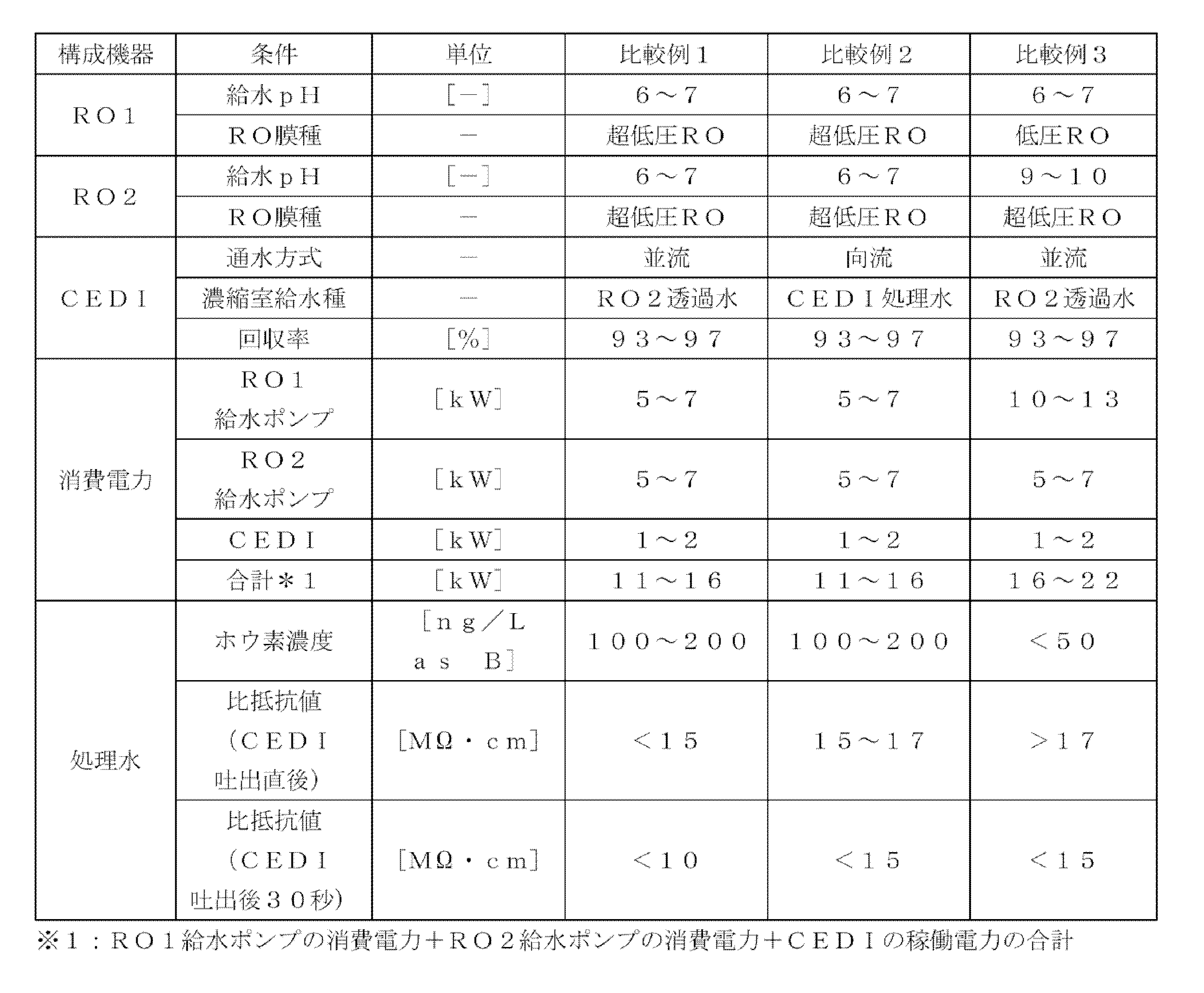
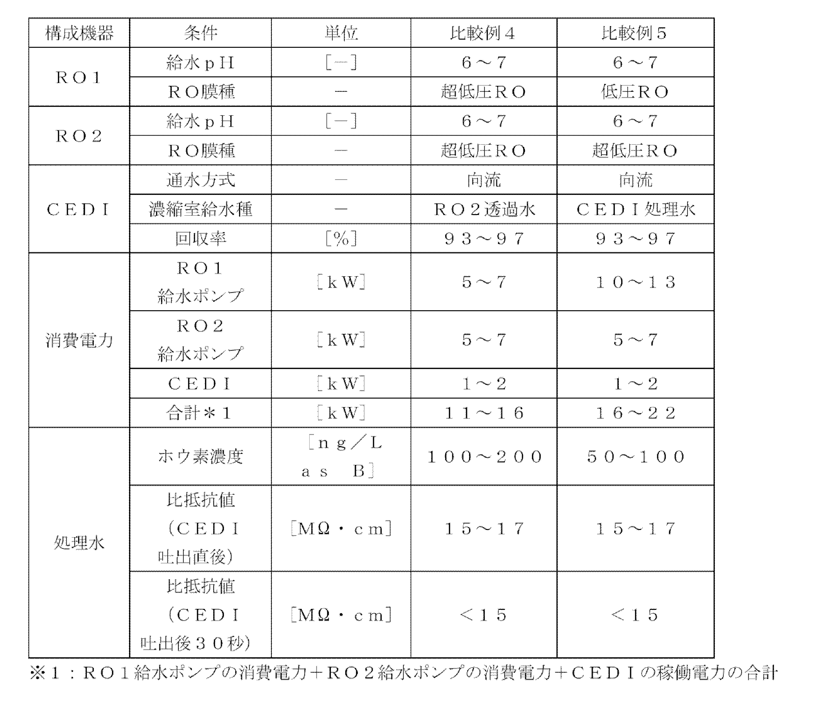
表1~表3から明らかなように、第一の逆浸透膜54及び第二の逆浸透膜58として超低圧逆浸透膜を使用し、第二の逆浸透膜58の給水(調整水)W5のpHを9~10とし、かつ電気再生式イオン交換装置59の通水方式を向流式とした実施例1~3では、より低消費電力で高純度な水質の処理水が得られることがわかる。
これに対し、第一の逆浸透膜54及び第二の逆浸透膜58として超低圧逆浸透膜を使用し、第二の逆浸透膜58の給水のpHを調整しない比較例1、2、4では、電気再生式イオン交換装置59の通水方式に関わらず、処理水W7の水質が実施例1,2に比べて悪かった。また、第一の逆浸透膜54として低圧逆浸透膜を使用し、第二の逆浸透膜58として超低圧逆浸透膜を使用した比較例3,5では、純度の高い処理水が得られるものの、消費電力が実施例1~3に比べて約40%増大した。さらに、電気再生式イオン交換装置59の通水方式を並流式とした比較例1,3では、電気再生式イオン交換装置59の脱塩室出口から30秒経過後の比抵抗値がさらに低下した。これは電気再生式イオン交換装置59の処理水W7中に存在する分子状CO2が時間の経過とともに解離して比抵抗値を低下させたためであると考えられる。
1 超純水製造システム
2 前処理装置
3 一次純水製造装置(純水製造システム)
4 サブシステム
5,6 逆浸透膜装置
7 電気再生式イオン交換装置
8 紫外線酸化装置
10 サブタンク
11 供給ポンプ
12 紫外線酸化装置
13 非再生型混床式イオン交換装置
14 限外ろ過膜(UF膜)
15 ユースポイント
21 第一の逆浸透膜装置
22 アルカリ添加手段(pH調整装置)
23 第二の逆浸透膜装置
24 電気再生式イオン交換装置
31 第一の逆浸透膜装置
32 アルカリ添加手段
33 第二の逆浸透膜装置
34,34A~34D 電気再生式イオン交換装置
41 給水管
41A~41D 分岐菅
42 合流管
42A~42D 流出管
43,43A~43D 比抵抗計
44A~44D 採水チューブ
51 純水製造装置(純水製造システム)
52 原水槽
53 第一の給水ポンプ
54 第一の逆浸透膜
55 透過水タンク
56 アルカリ添加手段
57 第二の給水ポンプ
58 第二の逆浸透膜
59 電気再生式イオン交換装置(CEDI)
60 処理水槽
W 原水
W1 前処理水
W2 一次純水(純水)
W3 超純水
W4 被処理水
W5 調整水
W6 第二の逆浸透膜装置の透過水
W7 電気再生式イオン交換装置の処理水
2 前処理装置
3 一次純水製造装置(純水製造システム)
4 サブシステム
5,6 逆浸透膜装置
7 電気再生式イオン交換装置
8 紫外線酸化装置
10 サブタンク
11 供給ポンプ
12 紫外線酸化装置
13 非再生型混床式イオン交換装置
14 限外ろ過膜(UF膜)
15 ユースポイント
21 第一の逆浸透膜装置
22 アルカリ添加手段(pH調整装置)
23 第二の逆浸透膜装置
24 電気再生式イオン交換装置
31 第一の逆浸透膜装置
32 アルカリ添加手段
33 第二の逆浸透膜装置
34,34A~34D 電気再生式イオン交換装置
41 給水管
41A~41D 分岐菅
42 合流管
42A~42D 流出管
43,43A~43D 比抵抗計
44A~44D 採水チューブ
51 純水製造装置(純水製造システム)
52 原水槽
53 第一の給水ポンプ
54 第一の逆浸透膜
55 透過水タンク
56 アルカリ添加手段
57 第二の給水ポンプ
58 第二の逆浸透膜
59 電気再生式イオン交換装置(CEDI)
60 処理水槽
W 原水
W1 前処理水
W2 一次純水(純水)
W3 超純水
W4 被処理水
W5 調整水
W6 第二の逆浸透膜装置の透過水
W7 電気再生式イオン交換装置の処理水
Claims (6)
- 被処理水が供給される膜面有効圧が0.4~0.9MPaの第一の超低圧型逆浸透膜装置と、
前記第一の超低圧型逆浸透膜装置の透過水のpHを8~11に調整するpH調整装置と、
前記pH調整装置によってpH調整された調整水が供給される膜面有効圧が0.4~0.9MPaの第二の超低圧型逆浸透膜装置と、
前記第二の超低、圧型逆浸透膜装置からの透過水が供給される電気再生式イオン交換装置と
を有する、純水製造システム。 - 前記電気再生式イオン交換装置の脱塩室の通水方向と向流となるように濃縮室を通水し、該濃縮室に電気再生式イオン交換装置の給水または処理水を通水する、請求項1に記載の純水製造システム。
- 前記電気再生式イオン交換装置の脱塩室から吐出された後10秒以上経過した処理水の比抵抗値又は導電率を測定する比抵抗計又は導電率計を有する、請求項1又は2に記載の純水製造システム。
- 被処理水を膜面有効圧が0.4~0.9MPaの第一の超低圧型逆浸透膜装置で処理する第一の逆浸透膜処理工程と、
前記第一の超低圧型逆浸透膜装置の透過水のpHを8~11に調整するpH調整工程と、
このpH調整工程によってpH調整された調整水を膜面有効圧が0.4~0.9MPaの第二の超低圧型逆浸透膜装置で処理する第二の逆浸透膜処理工程と、
前記第二の超低圧型逆浸透膜装置の透過水を電気再生式イオン交換装置で処理する処理水を得る脱イオン工程と
を有する純水製造方法。 - 前記脱イオン工程において、前記電気再生式イオン交換装置の脱塩室の通水方向と向流となるように濃縮室を通水し、該濃縮室に電気再生式イオン交換装置の給水または処理水を通水する、請求項4に記載の純水製造方法。
- 前記脱イオン工程で得られた処理水の比抵抗値を、該処理水が前記電気再生式イオン交換装置の脱塩室から吐出されて10秒以上経過した後測定し、この測定した比抵抗値が15MΩ・cm以上となるように前記電気再生式イオン交換装置の運転条件を制御する、請求項4又は5に記載の純水製造方法。
Priority Applications (2)
| Application Number | Priority Date | Filing Date | Title |
|---|---|---|---|
| KR1020257032673A KR20260029269A (ko) | 2023-06-29 | 2024-05-23 | 순수 제조 시스템 및 순수 제조 방법 |
| CN202480043767.4A CN121399069A (zh) | 2023-06-29 | 2024-05-23 | 纯水制造系统和纯水制造方法 |
Applications Claiming Priority (2)
| Application Number | Priority Date | Filing Date | Title |
|---|---|---|---|
| JP2023107337A JP7639856B2 (ja) | 2023-06-29 | 2023-06-29 | 純水製造システムおよび純水製造方法 |
| JP2023-107337 | 2023-06-29 |
Publications (1)
| Publication Number | Publication Date |
|---|---|
| WO2025004642A1 true WO2025004642A1 (ja) | 2025-01-02 |
Family
ID=93938268
Family Applications (1)
| Application Number | Title | Priority Date | Filing Date |
|---|---|---|---|
| PCT/JP2024/019109 Ceased WO2025004642A1 (ja) | 2023-06-29 | 2024-05-23 | 純水製造システムおよび純水製造方法 |
Country Status (5)
| Country | Link |
|---|---|
| JP (2) | JP7639856B2 (ja) |
| KR (1) | KR20260029269A (ja) |
| CN (1) | CN121399069A (ja) |
| TW (1) | TW202500515A (ja) |
| WO (1) | WO2025004642A1 (ja) |
Citations (6)
| Publication number | Priority date | Publication date | Assignee | Title |
|---|---|---|---|---|
| JPH095690A (ja) * | 1995-06-15 | 1997-01-10 | Citizen Watch Co Ltd | 陽極酸化装置 |
| JP2004025078A (ja) * | 2002-06-27 | 2004-01-29 | Ngk Insulators Ltd | 機能性超純水の製造方法及びそれに用いる装置 |
| JP2004283710A (ja) * | 2003-03-20 | 2004-10-14 | Kurita Water Ind Ltd | 純水製造装置 |
| WO2021131130A1 (ja) * | 2019-12-25 | 2021-07-01 | 栗田工業株式会社 | 超純水製造装置の制御方法 |
| WO2021235107A1 (ja) * | 2020-05-20 | 2021-11-25 | オルガノ株式会社 | ホウ素除去装置及びホウ素除去方法、並びに、純水製造装置及び純水の製造方法 |
| WO2024048115A1 (ja) * | 2022-08-31 | 2024-03-07 | オルガノ株式会社 | 水処理システムおよび水処理方法 |
Family Cites Families (3)
| Publication number | Priority date | Publication date | Assignee | Title |
|---|---|---|---|---|
| JP3575260B2 (ja) * | 1997-12-26 | 2004-10-13 | 栗田工業株式会社 | 純水製造装置 |
| JP6799657B1 (ja) * | 2019-10-24 | 2020-12-16 | オルガノ株式会社 | 水処理システム及び超純水製造システム並びに水処理方法 |
| JP7478617B2 (ja) * | 2020-07-30 | 2024-05-07 | オルガノ株式会社 | 純水製造装置及び超純水製造装置並びに純水製造方法及び超純水製造方法 |
-
2023
- 2023-06-29 JP JP2023107337A patent/JP7639856B2/ja active Active
-
2024
- 2024-05-23 WO PCT/JP2024/019109 patent/WO2025004642A1/ja not_active Ceased
- 2024-05-23 KR KR1020257032673A patent/KR20260029269A/ko active Pending
- 2024-05-23 CN CN202480043767.4A patent/CN121399069A/zh active Pending
- 2024-05-28 TW TW113119594A patent/TW202500515A/zh unknown
- 2024-10-15 JP JP2024180247A patent/JP2025010165A/ja active Pending
Patent Citations (6)
| Publication number | Priority date | Publication date | Assignee | Title |
|---|---|---|---|---|
| JPH095690A (ja) * | 1995-06-15 | 1997-01-10 | Citizen Watch Co Ltd | 陽極酸化装置 |
| JP2004025078A (ja) * | 2002-06-27 | 2004-01-29 | Ngk Insulators Ltd | 機能性超純水の製造方法及びそれに用いる装置 |
| JP2004283710A (ja) * | 2003-03-20 | 2004-10-14 | Kurita Water Ind Ltd | 純水製造装置 |
| WO2021131130A1 (ja) * | 2019-12-25 | 2021-07-01 | 栗田工業株式会社 | 超純水製造装置の制御方法 |
| WO2021235107A1 (ja) * | 2020-05-20 | 2021-11-25 | オルガノ株式会社 | ホウ素除去装置及びホウ素除去方法、並びに、純水製造装置及び純水の製造方法 |
| WO2024048115A1 (ja) * | 2022-08-31 | 2024-03-07 | オルガノ株式会社 | 水処理システムおよび水処理方法 |
Also Published As
| Publication number | Publication date |
|---|---|
| KR20260029269A (ko) | 2026-03-04 |
| JP2025006504A (ja) | 2025-01-17 |
| TW202500515A (zh) | 2025-01-01 |
| JP2025010165A (ja) | 2025-01-20 |
| JP7639856B2 (ja) | 2025-03-05 |
| CN121399069A (zh) | 2026-01-23 |
Similar Documents
| Publication | Publication Date | Title |
|---|---|---|
| JP6863510B1 (ja) | 超純水製造装置の制御方法 | |
| CN101827792B (zh) | 纯水制造装置及纯水制造方法 | |
| JP7347556B2 (ja) | 純水製造装置及び純水製造装置の運転方法 | |
| JP7520815B2 (ja) | 高度回収電気透析法 | |
| JP3951642B2 (ja) | 電気脱イオン装置の運転方法、電気脱イオン装置及び電気脱イオンシステム | |
| JP7103467B1 (ja) | 電気脱イオンシステム及び電気脱イオンシステムの制御方法 | |
| WO2020148961A1 (ja) | 純水製造装置およびその運転方法 | |
| JP2001191080A (ja) | 電気脱イオン装置及びそれを用いた電気脱イオン化処理方法 | |
| JP7639856B2 (ja) | 純水製造システムおよび純水製造方法 | |
| CN117062781B (zh) | 电去离子装置的控制方法 | |
| CN120603791A (zh) | 电去离子装置的运转方法 | |
| JP7205576B1 (ja) | 純水製造システムの運転方法 | |
| WO2024247898A1 (ja) | 電気脱イオン装置の脱塩水の水質測定方法 | |
| JP6720428B1 (ja) | 純水製造装置およびその運転方法 | |
| TW202534052A (zh) | 二級電去離子系統的運轉方法 | |
| JP4660890B2 (ja) | 電気脱イオン装置の運転方法 | |
| WO2026079320A1 (ja) | 電気脱イオン装置の制御方法 |
Legal Events
| Date | Code | Title | Description |
|---|---|---|---|
| 121 | Ep: the epo has been informed by wipo that ep was designated in this application |
Ref document number: 24831513 Country of ref document: EP Kind code of ref document: A1 |
|
| NENP | Non-entry into the national phase |
Ref country code: DE |