WO2025004516A1 - 蓄電池検査装置及び蓄電池検査方法 - Google Patents
蓄電池検査装置及び蓄電池検査方法 Download PDFInfo
- Publication number
- WO2025004516A1 WO2025004516A1 PCT/JP2024/016311 JP2024016311W WO2025004516A1 WO 2025004516 A1 WO2025004516 A1 WO 2025004516A1 JP 2024016311 W JP2024016311 W JP 2024016311W WO 2025004516 A1 WO2025004516 A1 WO 2025004516A1
- Authority
- WO
- WIPO (PCT)
- Prior art keywords
- storage battery
- magnetic field
- current flowing
- current
- vectors
- Prior art date
- Legal status (The legal status is an assumption and is not a legal conclusion. Google has not performed a legal analysis and makes no representation as to the accuracy of the status listed.)
- Ceased
Links
Images







Classifications
-
- G—PHYSICS
- G01—MEASURING; TESTING
- G01R—MEASURING ELECTRIC VARIABLES; MEASURING MAGNETIC VARIABLES
- G01R33/00—Arrangements or instruments for measuring magnetic variables
- G01R33/02—Measuring direction or magnitude of magnetic fields or magnetic flux
- G01R33/032—Measuring direction or magnitude of magnetic fields or magnetic flux using magneto-optic devices, e.g. Faraday or Cotton-Mouton effect
-
- G—PHYSICS
- G01—MEASURING; TESTING
- G01R—MEASURING ELECTRIC VARIABLES; MEASURING MAGNETIC VARIABLES
- G01R31/00—Arrangements for testing electric properties; Arrangements for locating electric faults; Arrangements for electrical testing characterised by what is being tested not provided for elsewhere
- G01R31/36—Arrangements for testing, measuring or monitoring the electrical condition of accumulators or electric batteries, e.g. capacity or state of charge [SoC]
-
- G—PHYSICS
- G01—MEASURING; TESTING
- G01R—MEASURING ELECTRIC VARIABLES; MEASURING MAGNETIC VARIABLES
- G01R31/00—Arrangements for testing electric properties; Arrangements for locating electric faults; Arrangements for electrical testing characterised by what is being tested not provided for elsewhere
- G01R31/36—Arrangements for testing, measuring or monitoring the electrical condition of accumulators or electric batteries, e.g. capacity or state of charge [SoC]
- G01R31/385—Arrangements for measuring battery or accumulator variables
-
- G—PHYSICS
- G01—MEASURING; TESTING
- G01R—MEASURING ELECTRIC VARIABLES; MEASURING MAGNETIC VARIABLES
- G01R31/00—Arrangements for testing electric properties; Arrangements for locating electric faults; Arrangements for electrical testing characterised by what is being tested not provided for elsewhere
- G01R31/36—Arrangements for testing, measuring or monitoring the electrical condition of accumulators or electric batteries, e.g. capacity or state of charge [SoC]
- G01R31/389—Measuring internal impedance, internal conductance or related variables
-
- G—PHYSICS
- G01—MEASURING; TESTING
- G01R—MEASURING ELECTRIC VARIABLES; MEASURING MAGNETIC VARIABLES
- G01R33/00—Arrangements or instruments for measuring magnetic variables
- G01R33/02—Measuring direction or magnitude of magnetic fields or magnetic flux
-
- G—PHYSICS
- G01—MEASURING; TESTING
- G01R—MEASURING ELECTRIC VARIABLES; MEASURING MAGNETIC VARIABLES
- G01R35/00—Testing or calibrating of apparatus covered by the other groups of this subclass
-
- H—ELECTRICITY
- H01—ELECTRIC ELEMENTS
- H01M—PROCESSES OR MEANS, e.g. BATTERIES, FOR THE DIRECT CONVERSION OF CHEMICAL ENERGY INTO ELECTRICAL ENERGY
- H01M10/00—Secondary cells; Manufacture thereof
- H01M10/42—Methods or arrangements for servicing or maintenance of secondary cells or secondary half-cells
- H01M10/48—Accumulators combined with arrangements for measuring, testing or indicating the condition of cells, e.g. the level or density of the electrolyte
-
- Y—GENERAL TAGGING OF NEW TECHNOLOGICAL DEVELOPMENTS; GENERAL TAGGING OF CROSS-SECTIONAL TECHNOLOGIES SPANNING OVER SEVERAL SECTIONS OF THE IPC; TECHNICAL SUBJECTS COVERED BY FORMER USPC CROSS-REFERENCE ART COLLECTIONS [XRACs] AND DIGESTS
- Y02—TECHNOLOGIES OR APPLICATIONS FOR MITIGATION OR ADAPTATION AGAINST CLIMATE CHANGE
- Y02E—REDUCTION OF GREENHOUSE GAS [GHG] EMISSIONS, RELATED TO ENERGY GENERATION, TRANSMISSION OR DISTRIBUTION
- Y02E60/00—Enabling technologies; Technologies with a potential or indirect contribution to GHG emissions mitigation
- Y02E60/10—Energy storage using batteries
Definitions
- This disclosure relates to a battery inspection device that inspects storage batteries.
- Patent Document 1 discloses technology relating to an evaluation device for inspecting secondary batteries.
- a controller calculates the magnitude of each of the multiple currents flowing through multiple parts of the secondary battery from the magnetic field detected by a magnetic sensor, and extracts the magnitude of the multiple currents in the electrolyte region located between the electrodes. The controller then creates a graph showing the distribution state of the magnitude of the multiple currents, and displays it on a display device.
- Secondary batteries are also called storage batteries.
- the magnetic sensor and the abnormal location are separated by a certain distance, so the sensing surface of the magnetic sensor is subjected to magnetic field lines resulting from the currents flowing through various parts of the battery, making it difficult to accurately visualize which parts of the battery are abnormal.
- Patent Document 1 is not based on a method for solving an analytical inverse problem, and cannot properly inspect the battery.
- the present disclosure provides a battery inspection device that can more appropriately inspect storage batteries.
- a storage battery inspection device includes an application unit that applies an AC current to a storage battery, a sensing unit that senses a magnetic field external to the storage battery, a calculation unit that calculates the AC current flowing through the storage battery based on the sensing result of the sensing unit, and a correction unit that calculates one or more vectors on a complex plane that represent the AC current flowing through the storage battery based on the calculation result of the calculation unit, calculates one or more projected vectors by projecting the one or more calculated vectors onto a predetermined straight line on the complex plane, and outputs a correction signal indicating the magnitude of the one or more calculated projected vectors.
- storage batteries can be inspected more appropriately.
- FIG. 1 is a block diagram showing a configuration of a storage battery inspection device according to an embodiment.
- FIG. 2 is a flowchart showing the operation of the storage battery inspection device according to the embodiment.
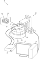
- FIG. 3 is a conceptual diagram showing a specific configuration of a storage battery inspection device according to an embodiment.
- FIG. 4 is a conceptual diagram showing a specific structure of the magnetic sensor according to the embodiment.
- FIG. 5 is a conceptual diagram showing a state in which a storage battery is being inspected in the embodiment.
- FIG. 6 is a conceptual diagram showing a circuit for applying an AC voltage in the embodiment.
- FIG. 7 is a conceptual diagram showing the overall configuration of a storage battery inspection device according to an embodiment.
- FIG. 8 is a block diagram showing a configuration of a detection circuit according to the embodiment.
- FIG. 1 is a block diagram showing a configuration of a storage battery inspection device according to an embodiment.
- FIG. 2 is a flowchart showing the operation of the storage battery inspection device according to the embodiment.
- FIG. 9 is a conceptual diagram showing an AC current flowing through a storage battery in the embodiment.
- FIG. 10 is a diagram showing complex numbers on a complex plane representing an AC current flowing through a storage battery in the embodiment, projected onto the vertical axis.
- FIG. 11 is a diagram showing an image generated based on the projected complex numbers shown in FIG.
- FIG. 12 is a diagram showing complex numbers on a complex plane representing an AC current flowing through a storage battery in the embodiment, projected onto a predetermined straight line.
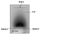
- FIG. 13 is a diagram showing an image generated based on the projected complex numbers shown in FIG.
- a storage battery inspection device includes an application unit that applies an AC current to a storage battery, a sensing unit that senses a magnetic field external to the storage battery, a calculation unit that calculates the AC current flowing through the storage battery based on the sensing result of the sensing unit, and a correction unit that calculates one or more vectors on a complex plane that represent the AC current flowing through the storage battery based on the calculation result of the calculation unit, calculates one or more projected vectors by projecting the one or more calculated vectors onto a predetermined straight line on the complex plane, and outputs a correction signal indicating the magnitude of the one or more calculated projected vectors.
- the magnetic sensor 12 is a sensor that detects magnetic field components. Specifically, the magnetic sensor 12 detects magnetic field components outside the storage battery and outputs a magnetic sensor signal indicating the detected magnetic field components. For example, the strength of the magnetic sensor signal output from the magnetic sensor 12 is proportional to the strength of the magnetic field components detected by the magnetic sensor 12. In this embodiment, the magnetic sensor 12 corresponds to the sensing unit.
- the preamplifier 18 is a circuit that amplifies a small signal. This provides a signal that can be used by subsequent circuits (such as the feedback circuit 14 and the high-pass filter 19). For example, the preamplifier 18 amplifies the magnetic sensor signal output from the magnetic sensor 12 and outputs the amplified magnetic sensor signal.
- the magnetic sensor signal output from the magnetic sensor 12 may be the magnetic sensor signal output from the magnetic sensor 12 and amplified by the preamplifier 18.
- the feedback circuit 14 is a circuit that applies a current as an input current to the canceling coil 13 based on the magnetic sensor signal output from the magnetic sensor 12. Specifically, the feedback circuit 14 obtains a low-frequency signal indicating a magnetic field component with a frequency lower than that of the alternating current from the magnetic sensor signal output from the magnetic sensor 12 when an alternating current is applied to the storage battery.
- the strength of the low-frequency signal is proportional to the strength of the magnetic field components at frequencies lower than the frequency of the alternating current.
- the low-frequency signal may represent magnetic field components at all frequencies lower than the frequency of the alternating current, or the low-frequency signal may represent magnetic field components at some frequencies lower than the frequency of the alternating current.
- the low-frequency signal may represent magnetic field components at frequencies lower than a reference frequency that is lower than the frequency of the alternating current.
- the low-frequency signal may also represent magnetic field components corresponding to a direct current component.
- the feedback circuit 14 applies a current as an input current to the canceling coil 13 based on the low-frequency signal. More specifically, the feedback circuit 14 applies a larger current as an input current to the canceling coil 13 the larger the low-frequency signal acquired from the magnetic sensor signal is, that is, the larger the magnetic field component with a frequency lower than the frequency of the AC current is.
- blocking frequency components lower than the cutoff frequency means suppressing the passage of frequency components lower than the cutoff frequency, and is not limited to completely blocking frequency components lower than the cutoff frequency.
- passing frequency components higher than the cutoff frequency means suppressing the blocking of frequency components higher than the cutoff frequency, and is not limited to completely passing frequency components higher than the cutoff frequency. The degree of blocking and passing depends on the quality of the high-pass filter 19.
- the high-pass filter 19 may block or pass components that are equal to the cutoff frequency, or may block some of the components that are equal to the cutoff frequency and pass others.
- the detection circuit 15 is a circuit that performs detection, and performs, for example, phase detection. Specifically, the detection circuit 15 obtains, as a detection signal, a signal that indicates a magnetic field component having the same frequency as the frequency of the AC current applied to the storage battery. More specifically, when an AC current is applied to the storage battery and an input current is applied to the cancel coil 13, the detection circuit 15 obtains, from the magnetic sensor signal output from the magnetic sensor 12, a detection signal that indicates a magnetic field component having the same frequency as the frequency of the AC current.
- the imaging circuit 16 has a calculation unit 76, a correction unit 77, and a generation unit 78, and is a circuit that generates an image. Specifically, the imaging circuit 16 generates an image that indicates the state of the storage battery based on the detection signal from the detection circuit 15. Here, the image can also be expressed as a video.
- the calculation unit 76 calculates the AC current flowing through the storage battery based on the detection result of the magnetic sensor 12. Specifically, the magnetic sensor 12 detects magnetic field components at each of a plurality of positions outside the storage battery, and the calculation unit 76 calculates the AC current flowing through each of a plurality of positions inside the storage battery by calculating the AC current based on the magnetic field components at each of the plurality of positions. The calculation unit 76 acquires the detection result of the magnetic sensor 12 via the detection circuit 15, etc.
- the display 17 is a device (information display circuit) that displays the image generated by the generation unit 78. Specifically, the display 17 has a screen, and displays the image generated by the imaging circuit 16 on the screen. In this embodiment, the display 17 corresponds to the display unit.
- the feedback circuit 14 applies a current as an input current to the canceling coil 13 based on the low-frequency signal lower than the frequency f 0 (S14).
- the canceling coil 13 generates a magnetic field component based on the input current. Specifically, the canceling coil 13 generates a low-frequency magnetic field component having a frequency lower than f0 , and cancels the low-frequency component having a frequency lower than f0 of the magnetic field applied to the magnetic sensor 12 (S15).
- the generation unit 78 of the imaging circuit 16 generates an image based on the output correction signal (S21).
- the power storage control circuit 11 is included in the power supply unit 23, and the imaging circuit 16 is included in the information processing unit 24.
- the feedback circuit 14 and the detection circuit 15 may each be included in the measurement unit 21, may each be included in the information processing unit 24, or may each be distributed and arranged in the measurement unit 21 and the information processing unit 24.
- the measurement unit 21 includes a magnetic sensor 12 as a probe, and a cancel coil 13 near the magnetic sensor 12.
- the measurement unit 21 measures the magnetic field via the magnetic sensor 12.
- the measurement unit 21 also includes a slidable mechanism that is composed of an actuator or the like. This allows the measurement unit 21 to scan the vicinity of the storage battery 31 using the magnetic sensor 12.
- the measurement unit 21 also includes a rotating table 22.
- the rotating table 22 is a table for placing the storage battery 31, which is the object to be inspected, and has a rotatable mechanism composed of an actuator or the like. This allows the measurement unit 21 to scan the vicinity of the storage battery 31 at various rotation angles using the magnetic sensor 12.
- the magnetic sensor 12 is located inside the canceling coil 13, and as the magnetic sensor 12 moves, the canceling coil 13 also moves.
- the specific example of the storage battery inspection device 10 shown in FIG. 1 is not limited to the example in FIG. 3.
- some components may be omitted, and other components may be added.
- some or all of the measurement unit 21, power supply unit 23, display 17, and information processing unit 24 shown in FIG. 3 may have an integrated structure.
- FIG. 4 is a conceptual diagram showing the specific structure of the magnetic sensor 12 shown in FIG. 3.
- the magnetic sensor 12 is composed of a TMR (Tunneling Magneto Resistive) element.
- the TMR element In a TMR element, an insulating film is sandwiched between magnetic films having a thickness of about 10 nm to 100 nm. More specifically, the TMR element is composed of multiple thin films: a soft layer 25, a tunnel layer 26, and a PIN layer (magnetically fixed layer) 27.
- the soft layer 25 is a magnetic film whose magnetization direction changes depending on the direction of magnetization in the external world.
- the PIN layer 27 is a magnetic film whose magnetization direction does not change.
- the tunnel layer 26 is an insulating film.
- the electrical resistance differs when the magnetization direction in the soft layer 25 and the magnetization direction in the PIN layer 27 are the same and when they are different. This change in electrical resistance is used to sense the magnetic field components.
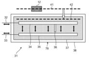
- FIG. 5 is a conceptual diagram showing the storage battery 31 shown in FIG. 3 being inspected.
- the storage battery 31 shown in FIG. 5 has a body 79 and a pair of electrode terminals 32 and 33 connected to the body 79.
- the body 79 includes a pair of electrode plates 34 and 35, an electrolyte 37, and a metal package 38.
- the pair of electrode plates 34 and 35 and the electrolyte 37 are covered by the metal package 38.
- magnetic field information of a reconstruction target surface 42 different from these scanned surfaces 41 may be calculated.
- the reconstruction target surface 42 may be a surface corresponding to the upper surface of the electrode plate 34.
- the magnetic field information of the reconstruction target surface 42 may be calculated using the magnetic field information of the multiple scanned surfaces 41 and Maxwell's equations.
- the conductivity distribution in the storage battery 31 and the AC current flowing through the storage battery 31 may be calculated using the magnetic field information of the scanned surface 41 or the reconstruction target surface 42 and Maxwell's equations.
- the calculation process as described above may be performed by the information processing unit 24 in FIG. 3, or by other components.
- the current flowing inside the storage battery 31 generates a magnetic field component outside the storage battery 31.
- the magnetic sensor 12 senses the magnetic field component that the current flowing inside the storage battery 31 generates outside the storage battery 31. If the current flowing inside the storage battery 31 changes, the magnetic field component outside the storage battery 31 also changes. In other words, the current flowing inside the storage battery 31 can be calculated using the magnetic field component outside the storage battery 31.
- metal may be precipitated on the electrode plate 34 or the electrode plate 35, causing dendrites 36 to form and grow inside the storage battery 31.
- the battery inspection device 10 can inspect the state of the occurrence and growth of dendrites 36 by sensing the magnetic field components generated by the alternating current flowing through the battery 31. In addition, the battery inspection device 10 can extract the magnetic field components that correspond to the frequency of the alternating current, thereby extracting the magnetic field components based on the internal electrical state of the battery 31. Therefore, the battery inspection device 10 can properly inspect the internal electrical state of the battery 31.
- the predetermined frequency is 1/( ⁇ s ⁇ s d s 2 ) when the electrical conductivity of the shielding part is ⁇ s , the magnetic permeability of the shielding part is ⁇ s , and the thickness of the shielding part is d s .
- the predetermined frequency is 1/( ⁇ s ⁇ s d s 2 ) when the electrical conductivity of the shielding part is ⁇ s , the magnetic permeability of the shielding part is ⁇ s , and the thickness of the shielding part is d s .
- FIG. 6 is a diagram showing a circuit for applying an AC voltage to the storage battery 31 shown in FIG. 3.
- the power storage control circuit 11 repeats charging and discharging at an angular frequency ⁇ in a state where a balance is maintained with respect to the output voltage ⁇ o (T) of the storage battery 31.
- the magnetic sensor 12 measures a magnetic field corresponding to a response component of the charging and discharging repeated at the angular frequency ⁇ .
- the storage battery 31 has a shielding portion that prevents the current inside the storage battery 31 from generating a magnetic field outside the storage battery 31.
- the magnetic field is shielded by the shielding portions such as the electrode plates 34 and 35 and the metal package 38, and does not leak outside the storage battery 31.
- the power storage control circuit 11 superimposes an AC voltage v a cos ⁇ t corresponding to a frequency lower than a frequency determined based on the conductivity of the shielding portion, the magnetic permeability of the shielding portion, and the thickness (depth) of the shielding portion on the DC voltage v e .
- the conductivity of the shielding portion is expressed by ⁇
- the magnetic permeability of the shielding portion is expressed by ⁇
- the thickness of the shielding portion is expressed by d
- the power storage control circuit 11 superimposes an AC voltage v a cos ⁇ t corresponding to a frequency f that satisfies f ⁇ 1/( ⁇ d 2 ).
- the thickness d of the shielding portion is, for example, the sum of the thickness of the electrode plate 34 and the thickness of the metal package 38.
- the storage control circuit 11 After measuring the magnetic field, the storage control circuit 11 stops superimposing the AC voltage and controls so that only charging or discharging is performed. For example, the storage control circuit 11 applies a DC voltage greater than the output voltage of the storage battery 31 to charge the storage battery 31. Alternatively, the storage control circuit 11 applies a DC voltage less than the output voltage of the storage battery 31 to discharge the storage battery 31. Alternatively, the storage control circuit 11 may discharge the storage battery 31 without applying a voltage.
- the storage control circuit 11 intermittently applies an external voltage in which an AC voltage is superimposed on a DC voltage to balance the output voltage of the storage battery 31 during the charging and discharging process.
- the storage control circuit 11 may apply the external voltage in which an AC voltage is superimposed periodically (cyclically) or irregularly.
- the storage control circuit 11 may apply the external voltage in which an AC voltage is superimposed automatically or based on manual operation.
- the magnetic sensor 12 measures the magnetic field around the storage battery 31 when the external voltage in which an AC voltage is superimposed is applied.
- each time for measuring the magnetic field during the charging and discharging process may be predetermined.
- the power storage control circuit 11 applies an external voltage with an AC voltage superimposed thereon to the storage battery 31 at each predetermined time during the charging and discharging process.
- the magnetic sensor 12 measures the magnetic field at each predetermined time during the charging and discharging process.
- the power storage control circuit 11 controls so that normal charging and discharging are performed. This allows the storage battery inspection device 10 to measure the magnetic field corresponding to each predetermined time during the charging and discharging process.
- the power storage control circuit 11 and the magnetic sensor 12 may be linked using a synchronization signal.
- the superposition of the AC voltage and the measurement of the magnetic field may be controlled by the synchronization signal so that they start and end simultaneously.
- the canceling coil 13 generates a magnetic field component based on the input current to cancel the magnetic field component generated by the residual magnetization.
- the input current is a current applied to the canceling coil 13 by the feedback circuit 14. This input current is also called a feedback current.
- the feedback circuit 14 includes a signal processing circuit 51 and a current amplifier circuit 52.
- the signal processing circuit 51 acquires the magnetic sensor signal output from the magnetic sensor 12 and amplified by the preamplifier 18, and outputs a control signal to the current amplifier circuit 52.
- the signal processing circuit 51 acquires a low-frequency signal from the magnetic sensor signal that indicates a magnetic field component with a frequency lower than the frequency of the alternating current. Then, based on the low-frequency signal, the signal processing circuit 51 outputs a control signal that indicates the magnitude of the feedback current to be applied to the cancel coil 13.
- the current amplifier circuit 52 applies a feedback current having a magnitude indicated by the control signal output from the signal processing circuit 51 to the cancel coil 13. This generates a magnetic field component for canceling the magnetic field component generated by residual magnetization, based on a magnetic field component with a frequency lower than the frequency of the AC current.
- the reference signal may be an AC voltage superimposed on a DC voltage in the storage control circuit 11, or an analog signal having the same frequency and phase as the AC current applied to the storage battery 31.
- the reference signal may also be the same as the AC signal applied to the storage battery 31.
- the reference signal may be an analog signal of the same voltage and current as the voltage and current applied to the storage battery 31.
- the reference signal may be an analog signal or digital signal indicating information on the voltage or current applied to the storage battery 31.
- the generating unit 78 acquires a correction signal from the correcting unit 77.
- the generating unit 78 generates an image showing the state of the storage battery 31 based on the acquired correction signal.
- this image shows the distribution of the alternating current flowing through the storage battery 31 as the state of the storage battery 31.
- this image may also show the magnetic field components near the surface of the storage battery 31, or the conductivity distribution of the storage battery 31, as the state of the storage battery 31.
- the imaging circuit 16 then outputs an image signal showing the generated image to the display 17.
- the DI71 is an impedance converter. Specifically, the DI71 acquires a reference signal output from the storage control circuit 11, adjusts the voltage and current ratio of the reference signal, and generates a reference signal for phase detection. For example, the reference signal is generated as a digital signal.
- the ADC 72 is a converter for converting an analog signal into a digital signal.
- a 16-bit AD converter or the like can be used as the ADC 72.
- the ADC 72 acquires the magnetic sensor signal output from the magnetic sensor 12 as an analog signal, and converts the magnetic sensor signal acquired as an analog signal into a digital signal.
- the detection circuit 15 stores the detection signal in the memory circuit 75.
- a digital circuit system is applied to the detection circuit 15, but an analog circuit system may also be applied to the detection circuit 15.
- the detection circuit 15 may obtain a detection signal indicating a magnetic field component of the same frequency as the AC current by performing detection processing on the magnetic sensor signal while it is still an analog signal.
- FIG. 9 is a conceptual diagram showing the AC current flowing through the storage battery 31 in the embodiment.
- FIG. 10 is a diagram showing complex numbers (one or more projected vectors) obtained by projecting complex numbers (one or more vectors) on a complex plane representing the AC current flowing through the storage battery 31 in the embodiment onto the vertical axis.
- FIG. 11 is a diagram showing an image generated based on the projected complex numbers (one or more projected vectors) shown in FIG. 10.
- FIG. 12 is a diagram showing complex numbers (one or more projected vectors) obtained by projecting complex numbers (one or more vectors) on a complex plane representing the AC current flowing through the storage battery in the embodiment onto a predetermined straight line.
- FIG. 13 is a diagram showing an image generated based on the projected complex numbers (one or more projected vectors) shown in FIG. 12.
- AC current flows through the storage battery 31.
- AC current input from one electrode terminal 32 passes through various paths inside the main body 79 and is output from the other electrode terminal 33 (see arrow B in FIG. 9).
- the AC current flowing through the entire main body 79 is approximately equal to the AC current flowing through the electrode terminal 32, and is also approximately equal to the AC current flowing through the electrode terminal 33.
- the magnetic sensor 12 senses magnetic fields at multiple positions outside the storage battery 31 by moving relative to the storage battery 31. Note that multiple magnetic sensors 12 may be used to sense magnetic fields at multiple positions outside the storage battery 31.
- the phase of the AC current flowing through each of the multiple positions in the main body 79 is essentially equal to the AC current flowing through the electrode terminal 32 or 33. However, if an abnormality occurs inside the main body 79, such as the formation of dendrites 36, the phase of the AC current flowing through the abnormal location in the main body 79 (see the dashed arrow in Figure 9) will be shifted from the phase of the AC current flowing through the electrode terminal 32 or 33. Specifically, the phase of the AC current flowing through the abnormal location in the main body 79 lags behind the phase of the AC current flowing through the electrode terminal 32 or 33.
- phase of the AC current flowing through normal parts of the main body 79 also shifts from the phase of the AC current flowing through the electrode terminal 32 or 33.
- the phase of the AC current flowing through normal parts of the main body 79 leads the phase of the AC current flowing through the electrode terminal 32 or 33.
- the correction unit 77 calculates one or more vectors on a complex plane representing the AC current flowing through the storage battery 31 based on the calculation result of the calculation unit 76.
- the vertical axis is the capacitance component (imaginary part), and the horizontal axis is the resistance component (real part).
- the length of the vector indicates the magnitude of the AC current
- the angle between the vector and the horizontal axis indicates the phase of the AC current.
- the calculation unit 76 calculates the effective value (magnitude) and phase of the AC current
- the correction unit 77 calculates one or more vectors on a complex plane representing the AC current flowing through the storage battery 31 based on the effective value and phase of the AC current calculated by the calculation unit 76.
- the correction unit 77 calculates a vector I all representing the AC current flowing throughout the main body 79, i.e., the AC current flowing through the electrode terminal 32 or 33, a vector I abnormal representing the AC current flowing through an abnormal portion of the main body 79, and a vector I normal representing the AC current flowing through a normal portion of the main body 79.
- Vector I abnormal is a vector obtained by adding up one or more vectors representing AC currents flowing through one or more abnormal locations in main body 79. For example, if there are two abnormal locations in main body 79, vector I abnormal is a vector obtained by adding up a vector representing an AC current flowing through one of the two abnormal locations and a vector representing an AC current flowing through the other one of the two abnormal locations.
- the vector I abnormal and the vector I normal are added together to obtain the vector I all .
- the vector I abnormal is not calculated, and the vector I normal is equal to the vector I all .
- the vector I normal and the vector I all are equal, it is found that no abnormality occurs in the main body 79.
- the correction unit 77 After calculating the projection vector I'abnormal and the projection vector I'normal , the correction unit 77 outputs a correction signal indicating the magnitude and direction of the projection vector I'abnormal and the magnitude and direction of the projection vector I'normal .
- the generation unit 78 generates an image showing the distribution of AC current in the storage battery 31 based on the correction signal, and the display 17 displays the image.
- the darker the color the greater the magnitude of the AC current indicated by the projection vector.
- the color tends to become darker toward the electrode terminals 32 and 33 in the main body 79, and that the magnitude of the AC current indicated by the projection vector tends to become greater.
- the projection vector I'abnormal faces the same direction as the projection vector I'normal . Therefore, the magnitude of the AC current indicated by the projection vector at an abnormal location is approximately equal to the magnitude of the AC current indicated by the projection vector at a normal location near the abnormal location.
- the predetermined straight line is a straight line C perpendicular to the vector I all .
- the correction unit 77 calculates the straight line C perpendicular to the vector I all , calculates a projection vector I'abnormal by projecting the vector I abnormal onto the straight line C, and calculates a projection vector I'normal by projecting the vector I normal onto the straight line C, and outputs a correction signal indicating the magnitude and direction of the projection vector I'abnormal and the magnitude and direction of the projection vector I'normal .
- the generation unit 78 generates an image showing the distribution of AC current in the storage battery 31 based on the correction signal, and the display 17 displays the image.
- the darker the color the greater the magnitude of the AC current indicated by the projection vector. Looking at the image of FIG. 13, it can be seen that the color of part of the main body 79 is darker.
- the projection vector I' abnormal faces the opposite side to the projection vector I' normal . Therefore, it is possible to increase the difference between the magnitude of the AC current indicated by the projection vector at an abnormal location and the magnitude of the AC current indicated by the projection vector at a normal location near the abnormal location.
- the direction in which the projection vector I' abnormal faces is defined as the positive side.
- the predetermined straight line is a straight line perpendicular to the vector I all
- the present invention is not limited to this.
- the predetermined straight line may be a straight line perpendicular to the vector I normal , or a straight line perpendicular to the vector I abnormal .
- the predetermined straight line may be a straight line that is not perpendicular to the vector I all , and in which the direction of the projection vector I' normal and the direction of the projection vector I' abnormal are opposite to each other.
- the battery inspection device 10 in the embodiment includes a storage control circuit 11 that applies an AC current to the storage battery 31, a magnetic sensor 12 that senses a magnetic field outside the storage battery 31, a calculation unit 76 that calculates the AC current flowing through the storage battery 31 based on the detection result of the magnetic sensor 12, and a correction unit 77 that calculates one or more vectors I abnormal , I normal on a complex plane that represent the AC current flowing through the storage battery 31 based on the calculation result of the calculation unit 76, calculates one or more projected vectors I' abnormal , I' normal by projecting the calculated one or more vectors I abnormal , I normal onto a specified straight line on the complex plane, and outputs a correction signal indicating the magnitude of the calculated one or more projected vectors I' abnormal , I' normal .
- the storage battery 31 has a main body 79 and electrode terminals 32 and 33 connected to the main body 79, and the predetermined straight line is perpendicular to vector I all on a complex plane that represents the AC current flowing throughout the main body 79.
- the direction of the vector Iabnormal representing the AC current flowing through an abnormal portion of the main body 79 and the direction of the vector Inormal representing the AC current flowing through a normal portion of the main body 79 are opposite to each other. Therefore, by calculating the projection vectors I'abnormal and I'normal as described above, it is possible to increase the difference between the output value indicating the magnitude of the AC current flowing through the abnormal portion of the main body 79 and the output value indicating the magnitude of the AC current flowing through the normal portion of the main body 79, making it easier to distinguish between the abnormal portion and the normal portion. This allows the storage battery 31 to be inspected more appropriately.
- the battery inspection device 10 in the embodiment further includes a generation unit 78 that generates an image showing the distribution of the AC current flowing through the battery 31 based on the correction signal output by the correction unit 77, and a display 17 that displays the image generated by the generation unit 78.
- the battery inspection method including the steps performed by each component of the battery inspection device may be executed by any device or system.
- a part or all of the battery inspection method may be executed by a computer including a processor, memory, input/output circuitry, etc.
- the battery inspection method may be executed by the computer executing a program for causing the computer to execute the battery inspection method.
- the above program may also be recorded on a non-transitory computer-readable recording medium.
- each component of the storage battery inspection device may be configured with dedicated hardware, or may be configured with general-purpose hardware that executes the above-mentioned programs, etc., or may be configured with a combination of these.
- the general-purpose hardware may be configured with a memory in which the program is recorded, and a general-purpose processor that reads and executes the program from the memory, etc.
- the memory may be a semiconductor memory or a hard disk, etc.
- the general-purpose processor may be a CPU, etc.
- the dedicated hardware may also be configured with a memory and a dedicated processor.
- the dedicated processor may execute the above-mentioned battery inspection method by referring to a memory for recording measurement data.
- each component of the storage battery inspection device may be an electric circuit.
- These electric circuits may form a single electric circuit as a whole, or each may be a separate electric circuit.
- these electric circuits may correspond to dedicated hardware, or may correspond to general-purpose hardware that executes the above-mentioned programs, etc.
- One aspect of the present disclosure is useful for a battery inspection device that inspects storage batteries, and can be applied to battery manufacturing systems, etc.
Landscapes
- Physics & Mathematics (AREA)
- General Physics & Mathematics (AREA)
- Engineering & Computer Science (AREA)
- Condensed Matter Physics & Semiconductors (AREA)
- Chemical Kinetics & Catalysis (AREA)
- General Chemical & Material Sciences (AREA)
- Electrochemistry (AREA)
- Chemical & Material Sciences (AREA)
- Manufacturing & Machinery (AREA)
- Power Engineering (AREA)
- Secondary Cells (AREA)
- Quality & Reliability (AREA)
- Computer Vision & Pattern Recognition (AREA)
- Theoretical Computer Science (AREA)
Priority Applications (6)
| Application Number | Priority Date | Filing Date | Title |
|---|---|---|---|
| EP24831391.8A EP4733784A1 (en) | 2023-06-26 | 2024-04-25 | Storage battery inspection device and storage battery inspection method |
| AU2024305975A AU2024305975A1 (en) | 2023-06-26 | 2024-04-25 | Storage battery inspection device and storage battery inspection method |
| IL325085A IL325085A (en) | 2023-06-26 | 2024-04-25 | Storage battery inspection device and storage battery inspection method |
| KR1020257039335A KR20260027885A (ko) | 2023-06-26 | 2024-04-25 | 축전지 검사 장치 및 축전지 검사 방법 |
| CN202480034563.4A CN121195177A (zh) | 2023-06-26 | 2024-04-25 | 蓄电池检查装置以及蓄电池检查方法 |
| JP2025529468A JPWO2025004516A1 (https=) | 2023-06-26 | 2024-04-25 |
Applications Claiming Priority (2)
| Application Number | Priority Date | Filing Date | Title |
|---|---|---|---|
| JP2023-103925 | 2023-06-26 | ||
| JP2023103925 | 2023-06-26 |
Publications (1)
| Publication Number | Publication Date |
|---|---|
| WO2025004516A1 true WO2025004516A1 (ja) | 2025-01-02 |
Family
ID=93938096
Family Applications (1)
| Application Number | Title | Priority Date | Filing Date |
|---|---|---|---|
| PCT/JP2024/016311 Ceased WO2025004516A1 (ja) | 2023-06-26 | 2024-04-25 | 蓄電池検査装置及び蓄電池検査方法 |
Country Status (8)
| Country | Link |
|---|---|
| EP (1) | EP4733784A1 (https=) |
| JP (1) | JPWO2025004516A1 (https=) |
| KR (1) | KR20260027885A (https=) |
| CN (1) | CN121195177A (https=) |
| AU (1) | AU2024305975A1 (https=) |
| IL (1) | IL325085A (https=) |
| TW (1) | TW202501017A (https=) |
| WO (1) | WO2025004516A1 (https=) |
Citations (7)
| Publication number | Priority date | Publication date | Assignee | Title |
|---|---|---|---|---|
| JPH11142465A (ja) * | 1997-11-05 | 1999-05-28 | Fuji Electric Co Ltd | 地絡故障点検出方法 |
| JP2013032985A (ja) | 2011-08-02 | 2013-02-14 | Pulstec Industrial Co Ltd | 2次電池の評価装置及び評価方法 |
| WO2015136930A1 (ja) * | 2014-03-13 | 2015-09-17 | 国立大学法人神戸大学 | 電池検査装置および電池検査方法 |
| WO2015136931A1 (ja) * | 2014-03-12 | 2015-09-17 | 国立大学法人神戸大学 | 導電率分布導出方法および導電率分布導出装置 |
| WO2017187791A1 (ja) * | 2016-04-28 | 2017-11-02 | 国立大学法人神戸大学 | 計測装置および計測方法 |
| WO2021024859A1 (ja) * | 2019-08-06 | 2021-02-11 | 株式会社 Integral Geometry Science | 蓄電池検査装置及び蓄電池検査方法 |
| WO2024009894A1 (ja) * | 2022-07-07 | 2024-01-11 | 株式会社 Integral Geometry Science | 測定装置および測定方法 |
-
2024
- 2024-04-25 AU AU2024305975A patent/AU2024305975A1/en active Pending
- 2024-04-25 IL IL325085A patent/IL325085A/en unknown
- 2024-04-25 KR KR1020257039335A patent/KR20260027885A/ko active Pending
- 2024-04-25 EP EP24831391.8A patent/EP4733784A1/en active Pending
- 2024-04-25 JP JP2025529468A patent/JPWO2025004516A1/ja active Pending
- 2024-04-25 TW TW113115373A patent/TW202501017A/zh unknown
- 2024-04-25 CN CN202480034563.4A patent/CN121195177A/zh active Pending
- 2024-04-25 WO PCT/JP2024/016311 patent/WO2025004516A1/ja not_active Ceased
Patent Citations (7)
| Publication number | Priority date | Publication date | Assignee | Title |
|---|---|---|---|---|
| JPH11142465A (ja) * | 1997-11-05 | 1999-05-28 | Fuji Electric Co Ltd | 地絡故障点検出方法 |
| JP2013032985A (ja) | 2011-08-02 | 2013-02-14 | Pulstec Industrial Co Ltd | 2次電池の評価装置及び評価方法 |
| WO2015136931A1 (ja) * | 2014-03-12 | 2015-09-17 | 国立大学法人神戸大学 | 導電率分布導出方法および導電率分布導出装置 |
| WO2015136930A1 (ja) * | 2014-03-13 | 2015-09-17 | 国立大学法人神戸大学 | 電池検査装置および電池検査方法 |
| WO2017187791A1 (ja) * | 2016-04-28 | 2017-11-02 | 国立大学法人神戸大学 | 計測装置および計測方法 |
| WO2021024859A1 (ja) * | 2019-08-06 | 2021-02-11 | 株式会社 Integral Geometry Science | 蓄電池検査装置及び蓄電池検査方法 |
| WO2024009894A1 (ja) * | 2022-07-07 | 2024-01-11 | 株式会社 Integral Geometry Science | 測定装置および測定方法 |
Non-Patent Citations (6)
| Title |
|---|
| KENJIRO KIMURA; KAI YABUMOTO; SHOGO SUZUKI; KIYOSHI MATSUDA; YUKI MIMA; NORIAKI KIMURA: "3A12 Research of visualization method of current density distribution inside storage battery and identification of self-discharge point", LECTURE ABSTRACTS OF THE 61ST BATTERY SYMPOSIUM IN JAPAN; NOVEMBER 18-20, 2020, JP, vol. 61, 20 November 2020 (2020-11-20) - 20 November 2020 (2020-11-20), JP, pages 3A12, XP009559587 * |
| KIMURA KENJIRO, MATSUDA, SEIJU: "Development of imaging technology for current density distribution inside storage batteries", KANSAI ELECTROCHEMICAL TEXT SERIES. DENKI KAGAKU SEMINAR 'INDUSTRIAL POLICIES AND PROJECT TRENDS SURROUNDING BATTERIES'. THE KANSAI BRANCH OF THE ELECTROCHEMICAL SOCIETY OF JAPAN, 13 July 2022 (2022-07-13), XP093252702, DOI: 10.5796/ecsjkansai.2022.1.01008 * |
| KIMURA, K. NOMOTO, K. MIMA, Y. INAO, T. OYABU, N. KIMURA, N.: "2R02 Development of magnetic imaging system with electromagnetic reconstruction method and its application to nondestructive inspection of rechargeable battery", 81ST ANNUAL MEETING OF THE ELECTROCHEMICAL SOCIETY OF JAPAN ECSJ; OSAKA, JAPAN; MARCH 29-31, 2014, ELECTRICAL AND CHEMICAL SOCIETY OF JAPAN, vol. 81, 29 March 2014 (2014-03-29) - 31 March 2014 (2014-03-31), pages 383, XP009560846 * |
| KIMURA, KENJIRO. OKADA, HIDEAKI. MATSUDA, SEIJU. NISHIMURA, YUTARO. MIZUTANI, TAKAO. SUZUKI, SHOGO. MIMA, YUKI. KIMURA, NORIAKI: "3C07 Non-destructive measurement of electric current distribution in storage battery containing magnetic materials", PROCEEDINGS OF THE 63RD BATTERY SYMPOSIUM IN JAPAN; FUKUOKA, JAPAN; NOVEMBER 8-10, 2022, JP, vol. 63, 10 November 2022 (2022-11-10) - 10 November 2022 (2022-11-10), JP, pages 3C07, XP009559588 * |
| MATSUDA SEIJU, SUZUKI SHOGO, YABUMOTO KAI, OKADA HIDEAKI, MIMA YUKI, KIMURA NORIAKI, KIMURA KENJIRO: "Real-time Imaging of the Electric Conductivity Distribution inside a Rechargeable Battery Cell", ELECTROCHEMISTRY, ELECTROCHEMICAL SOCIETY OF JAPAN,, JP, vol. 89, no. 5, 5 September 2021 (2021-09-05), JP , pages 420 - 426, XP093252705, ISSN: 1344-3542, DOI: 10.5796/electrochemistry.21-00007 * |
| SUZUKI SHOGO, OKADA HIDEAKI, YABUMOTO KAI, MATSUDA SEIJU, MIMA YUKI, KIMURA NORIAKI, KIMURA KENJIRO: "Non-destructive visualization of short circuits in lithium-ion batteries by a magnetic field imaging system", JAPANESE JOURNAL OF APPLIED PHYSICS, JAPAN SOCIETY OF APPLIED PHYSICS, JP, vol. 60, no. 5, 1 May 2021 (2021-05-01), JP , pages 056502, XP093252707, ISSN: 0021-4922, DOI: 10.35848/1347-4065/abf4a1 * |
Also Published As
| Publication number | Publication date |
|---|---|
| KR20260027885A (ko) | 2026-03-03 |
| EP4733784A1 (en) | 2026-04-29 |
| TW202501017A (zh) | 2025-01-01 |
| JPWO2025004516A1 (https=) | 2025-01-02 |
| AU2024305975A1 (en) | 2026-01-15 |
| IL325085A (en) | 2026-02-01 |
| CN121195177A (zh) | 2025-12-23 |
Similar Documents
| Publication | Publication Date | Title |
|---|---|---|
| JP7452883B2 (ja) | 蓄電池検査装置及び蓄電池検査方法 | |
| Gatel et al. | Counting elementary charges on nanoparticles by electron holography | |
| JP6083613B2 (ja) | 磁気的非破壊検査装置 | |
| US7989766B2 (en) | Sample inspection apparatus | |
| TWI519796B (zh) | Distributed analysis device and distributed analysis method | |
| JP6745509B2 (ja) | 観測方法および観測装置 | |
| CN106133515A (zh) | 检查探头、检查系统以及检查方法 | |
| JP6461095B2 (ja) | 電池検査装置および電池検査方法 | |
| WO2025004516A1 (ja) | 蓄電池検査装置及び蓄電池検査方法 | |
| JP7482046B2 (ja) | 磁気センサ及び検査装置 | |
| JP7473114B2 (ja) | 外場応答分布可視化装置及び外場応答分布可視化方法 | |
| US20250164583A1 (en) | Magnetic sensor and magnetic measurement method | |
| JP7426955B2 (ja) | 磁気センサ及び検査装置 | |
| JP7426958B2 (ja) | 磁気センサ及び検査装置 | |
| JP7426956B2 (ja) | 磁気センサ及び検査装置 | |
| JP7496089B2 (ja) | 磁気センサ及び検査装置 | |
| JP7414703B2 (ja) | 磁気センサ及び検査装置 | |
| JP2019045275A (ja) | 磁気検出装置 | |
| JP2016219272A (ja) | 二次電池の検査方法 | |
| Caeiros et al. | A differential high-resolution motorized multi-projection approach for an experimental Magnetic Induction Tomography prototype | |
| CN117330971A (zh) | 新能源设备的检测方法、装置及检测设备 | |
| KR20190099201A (ko) | 차량 배터리 전류 감지 시스템 | |
| JP2022153075A (ja) | 計測装置、計測方法、およびプログラム | |
| Hejtmánek et al. | Reducing the Noise Level in a Gaussmeter with a Hall Probe for Reliable Magnetic Impedance Tomography |
Legal Events
| Date | Code | Title | Description |
|---|---|---|---|
| 121 | Ep: the epo has been informed by wipo that ep was designated in this application |
Ref document number: 24831391 Country of ref document: EP Kind code of ref document: A1 |
|
| ENP | Entry into the national phase |
Ref document number: 2025529468 Country of ref document: JP Kind code of ref document: A |
|
| WWE | Wipo information: entry into national phase |
Ref document number: 2025529468 Country of ref document: JP |
|
| WWE | Wipo information: entry into national phase |
Ref document number: CN2024800345634 Country of ref document: CN |
|
| WWE | Wipo information: entry into national phase |
Ref document number: 325085 Country of ref document: IL |
|
| WWE | Wipo information: entry into national phase |
Ref document number: AU2024305975 Country of ref document: AU |
|
| WWE | Wipo information: entry into national phase |
Ref document number: 202547127628 Country of ref document: IN |
|
| WWE | Wipo information: entry into national phase |
Ref document number: 202593431 Country of ref document: EA |
|
| ENP | Entry into the national phase |
Ref document number: 2024305975 Country of ref document: AU Date of ref document: 20240425 Kind code of ref document: A |
|
| ENP | Entry into the national phase |
Ref document number: 2024831391 Country of ref document: EP Effective date: 20260126 |
|
| WWE | Wipo information: entry into national phase |
Ref document number: 2024831391 Country of ref document: EP |
|
| NENP | Non-entry into the national phase |
Ref country code: DE |
|
| WWE | Wipo information: entry into national phase |
Ref document number: 11202508214Q Country of ref document: SG |
|
| WWP | Wipo information: published in national office |
Ref document number: 11202508214Q Country of ref document: SG |
|
| ENP | Entry into the national phase |
Ref document number: 2024831391 Country of ref document: EP Effective date: 20260126 |
|
| WWP | Wipo information: published in national office |
Ref document number: 325085 Country of ref document: IL |
|
| ENP | Entry into the national phase |
Ref document number: 2024831391 Country of ref document: EP Effective date: 20260126 |