WO2025004485A1 - ケーブル - Google Patents
ケーブル Download PDFInfo
- Publication number
- WO2025004485A1 WO2025004485A1 PCT/JP2024/013619 JP2024013619W WO2025004485A1 WO 2025004485 A1 WO2025004485 A1 WO 2025004485A1 JP 2024013619 W JP2024013619 W JP 2024013619W WO 2025004485 A1 WO2025004485 A1 WO 2025004485A1
- Authority
- WO
- WIPO (PCT)
- Prior art keywords
- metal
- mass
- cable
- metal layer
- insulating material
- Prior art date
- Legal status (The legal status is an assumption and is not a legal conclusion. Google has not performed a legal analysis and makes no representation as to the accuracy of the status listed.)
- Ceased
Links
Images






Classifications
-
- H—ELECTRICITY
- H01—ELECTRIC ELEMENTS
- H01B—CABLES; CONDUCTORS; INSULATORS; SELECTION OF MATERIALS FOR THEIR CONDUCTIVE, INSULATING OR DIELECTRIC PROPERTIES
- H01B11/00—Communication cables or conductors
- H01B11/02—Cables with twisted pairs or quads
- H01B11/06—Cables with twisted pairs or quads with means for reducing effects of electromagnetic or electrostatic disturbances, e.g. screens
-
- H—ELECTRICITY
- H01—ELECTRIC ELEMENTS
- H01B—CABLES; CONDUCTORS; INSULATORS; SELECTION OF MATERIALS FOR THEIR CONDUCTIVE, INSULATING OR DIELECTRIC PROPERTIES
- H01B7/00—Insulated conductors or cables characterised by their form
- H01B7/02—Disposition of insulation
-
- H—ELECTRICITY
- H01—ELECTRIC ELEMENTS
- H01B—CABLES; CONDUCTORS; INSULATORS; SELECTION OF MATERIALS FOR THEIR CONDUCTIVE, INSULATING OR DIELECTRIC PROPERTIES
- H01B7/00—Insulated conductors or cables characterised by their form
- H01B7/17—Protection against damage caused by external factors, e.g. sheaths or armouring
- H01B7/18—Protection against damage caused by wear, mechanical force or pressure; Sheaths; Armouring
Definitions
- In-vehicle information cables consist of conductors made of metals such as copper covered with insulating material made of polyolefin resin. Since transmission loss is positively correlated with the frequency of the signal and the dielectric tangent of the insulating material, in order to increase the speed of signal transmission, it is necessary to reduce the dielectric tangent of the insulating material, further reducing transmission loss and ensuring stable signal transmission.
- In-vehicle information electric wires are generally used as in-vehicle information transmission cables, with one or more in-vehicle information electric wires covered with a sheath material for mechanical protection and to improve flame retardancy, oil resistance, etc.
- In-vehicle information transmission cables are sometimes used bundled with wires, cables, and wire harnesses that use polyvinyl chloride (hereinafter also referred to as "PVC (polyvinyl chloride)" as the sheath material.
- PVC polyvinyl chloride
- the antioxidant contained in the insulation of the in-vehicle information transmission cable may migrate to the PVC of the surrounding electric wires, etc., causing the insulation of the in-vehicle information transmission cable to oxidize and deteriorate, or hydrochloric acid gas generated from the PVC of the surrounding electric wires, etc. may cause the insulation of the in-vehicle information transmission cable to deteriorate.
- Patent Document 1 discloses a technology that suppresses the deterioration of the insulation of an in-vehicle information transmission cable when the in-vehicle information transmission cable is bundled with a wire harness having an insulation material made of PVC. Specifically, a large amount of antioxidant is added to the insulation material to suppress the deterioration of the insulation material.
- the cable of the present disclosure comprises: A cable comprising an electric wire and a metal layer covering the electric wire,
- the electric wire includes a conductor and an insulating material provided on an outer peripheral surface of the conductor,
- the insulating material includes a polyolefin resin, a phenolic antioxidant, and a copper inhibitor;
- the content of the polyolefin resin in the insulating material is 98% by mass or more, the insulating material contains, relative to 100 parts by mass of the polyolefin resin, 0.01 parts by mass or more and 0.5 parts by mass or less of the phenol-based antioxidant and 0.01 parts by mass or more and 0.5 parts by mass or less of the copper inhibitor, and has a dielectric loss tangent at 10 GHz of 3.0 ⁇ 10-4 or less;
- the metal layer includes a longitudinally attached metal layer formed by longitudinally attaching a metal tape, The metal tapes overlap each other in a width direction of the metal tapes to form an overlapping portion, The width of the overlapping portion of the
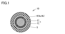
- FIG. 1 is a schematic cross-sectional view of a cable according to a first embodiment and a second embodiment.
- FIG. 2 is a schematic cross-sectional view of a cable according to a third embodiment.
- FIG. 3 is a diagram for explaining the vertical attachment of the metal tape.
- FIG. 4 is a diagram for explaining the horizontal winding of the metal tape.
- FIG. 5A is a schematic cross-sectional view of an example of a cable according to a fourth embodiment.
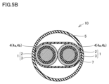
- FIG. 5B is a schematic cross-sectional view of another example of the cable according to the fourth embodiment.
- FIG. 6A is a schematic cross-sectional view of an example of a cable according to a fifth embodiment.
- FIG. 6B is a schematic cross-sectional view of another example of the cable according to the fifth embodiment.
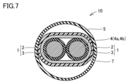
- FIG. 7 is a schematic cross-sectional view of a cable according to a sixth embodiment.
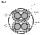
- FIG. 8 is a schematic cross-sectional view of another example of the cable according to the sixth embodiment.
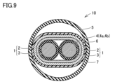
- FIG. 9 is a schematic cross-sectional view of a cable according to the seventh embodiment.
- FIG. 10 is a schematic cross-sectional view of another example of the cable according to the seventh embodiment.
- FIG. 11A is a cross-sectional view of an example of a test structure used in an insulation degradation suppression evaluation test.
- FIG. 11B is a cross-sectional view of another example of a test structure used in an insulation degradation suppression evaluation test.
- the present disclosure therefore aims to provide a cable in which the dielectric tangent of the cable insulation does not increase and degradation of the cable insulation is suppressed, even when the cable is bundled with a wire harness having insulation made of PVC.
- Degradation of the insulation refers to both heat aging and degradation caused by harmful gases generated by PVC.
- the cable of the present disclosure has A cable comprising an electric wire and a metal layer covering the electric wire,
- the electric wire includes a conductor and an insulating material provided on an outer peripheral surface of the conductor,
- the insulating material includes a polyolefin resin, a phenolic antioxidant, and a copper inhibitor;
- the content of the polyolefin resin in the insulating material is 98% by mass or more, the insulating material contains, relative to 100 parts by mass of the polyolefin resin, 0.01 parts by mass or more and 0.5 parts by mass or less of the phenol-based antioxidant and 0.01 parts by mass or more and 0.5 parts by mass or less of the copper inhibitor, and has a dielectric loss tangent at 10 GHz of 3.0 ⁇ 10-4 or less;
- the metal layer includes a longitudinally attached metal layer formed by longitudinally attaching a metal tape, The metal tapes overlap each other in a width direction of the metal
- the cable of the present disclosure is A cable comprising an electric wire and a metal layer covering the electric wire,
- the electric wire includes a conductor and an insulating material provided on an outer peripheral surface of the conductor,
- the insulating material includes a polyolefin resin, a phenolic antioxidant, and a copper inhibitor;
- the content of the polyolefin resin in the insulating material is 98% by mass or more, the insulating material contains, relative to 100 parts by mass of the polyolefin resin, 0.01 parts by mass or more and 0.5 parts by mass or less of the phenol-based antioxidant and 0.01 parts by mass or more and 0.5 parts by mass or less of the copper inhibitor, and has a dielectric loss tangent at 10 GHz of 3.0 ⁇ 10-4 or less;
- the metal layer includes a horizontally wound metal layer formed by horizontally winding a metal tape, The metal tapes overlap each other in a width direction of the metal tapes to form an overlapping portion, The width of the overlapping portion is equal to
- the insulating material of the cable disclosed herein contains a polyolefin resin and a phenolic antioxidant.
- the amount of the phenolic antioxidant is 0.01 parts by mass or more and 0.5 parts by mass or less per 100 parts by mass of the polyolefin resin, so the amount of the phenolic antioxidant is small. Therefore, the dielectric tangent of the insulating material does not increase, and oxidative deterioration of the insulating material is suppressed.
- the metal layer of the cable disclosed herein also has a shielding effect to prevent hydrochloric acid gas generated from the PVC of the surrounding wire harness from penetrating into the inside of the cable. This prevents hydrochloric acid gas from reaching the insulation of the cable, suppressing deterioration of the insulation.
- the metal layer of the cable disclosed herein also has a noise blocking effect. Therefore, the cable disclosed herein can transmit signals reliably.
- the cable disclosed herein has a small dielectric tangent and is particularly suitable for high-speed transmission.
- the cable includes a plurality of the electric wires
- the metal layer may cover each of the wires.
- the cable has a first electric wire group consisting of two or more electric wires,
- the metal layer may collectively cover the first group of electric wires.
- the cable may further include a metal braid covering the surface of the metal layer opposite to the surface facing the electric wire.
- This provides a higher noise shielding effect and makes wiring easier and easier to bend.
- the metal tape includes a thin metal layer,
- the metal thin layer may have a thickness of 0.1 ⁇ m or more and 20 ⁇ m or less.
- the polyolefin resin may be a polypropylene resin.
- the cable further includes an outer sheath covering the metal layer.
- the outer covering material contains a polyolefin resin and a metal hydroxide,
- the metal hydroxide is at least one selected from the group consisting of magnesium hydroxide and aluminum hydroxide,
- the outer covering material may contain 50 parts by mass or more and 200 parts by mass or less of the metal hydroxide per 100 parts by mass of the polyolefin resin.
- the metal tape includes a laminated structure in which a base film, an adhesive layer, and a thin metal layer are laminated in the above order,
- the base film is made of polyethylene terephthalate,
- the thin metal layer may include aluminum or copper.
- the metal tape may be aluminum foil or copper foil.
- the cable includes two of the electric wires, The two electric wires may be twisted in a pair.
- the cable includes two of the electric wires,
- the two electric wires may be laterally wound with a resin tape.
- a ⁇ B means the upper and lower limits of a range (i.e., greater than or equal to A and less than or equal to B). If no unit is stated for A and only a unit is stated for B, the units of A and B are the same.
- any one numerical value listed as the lower limit and any one numerical value listed as the upper limit is also considered to be disclosed.
- a1 or more, b1 or more, and c1 or more are listed as the lower limit and a2 or less, b2 or less, and c2 or less are listed as the upper limit, a1 or more and a2 or less, a1 or more and b2 or less, a1 or more and c2 or less, b1 or more and a2 or less, b1 or more and b2 or less, b1 or more and c2 or less, c1 or more and a2 or less, c1 or more and b2 or less, and c1 or more and c2 or less are considered to be disclosed.
- Fig. 1 is a schematic cross-sectional view of a cable 10 according to embodiment 1.
- the cable 10 according to embodiment 1 includes an electric wire 1, a metal layer 4 covering the electric wire 1, and an outer covering material 5.
- the electric wire 1 includes one conductor 2 and an insulating material 3 provided on the outer peripheral surface of the conductor 2.
- the metal layer 4 includes a vertically attached metal layer 4a formed by vertically attaching a metal tape. The metal tapes partially overlap in the width direction of the metal tape to form an overlapping portion, and the width of the overlapping portion is 1/20 to 1/3 of the width of the metal tape.
- an electric wire 1 includes one conductor 2 and an insulating material 3 provided on the outer peripheral surface of the conductor 2 .
- the material of the conductor 2 is preferably a metal material having high electrical conductivity and high mechanical strength. Examples of such metal materials include copper, copper alloys, aluminum, aluminum alloys, nickel, silver, soft iron, steel, and stainless steel.
- the conductor 2 can be a wire material formed into a wire shape from one type of metal material.
- the conductor 2 can also be a multilayer structure in which the wire material is further coated with another metal by a technique such as plating. Examples of the conductor 2 having a multilayer structure include a tin-plated copper wire, a nickel-plated copper wire, a silver-plated copper wire, a copper-plated aluminum wire, and a copper-plated steel wire.
- the shape of the conductor 2 is not particularly limited, and any shape known in the art can be used. Examples of the shape of the conductor 2 include a round wire with a circular cross section, a rectangular wire with a square cross section, a rectangular flat wire, and a twisted wire made by twisting together multiple strands.
- the average cross-sectional area of the conductor 2 is not particularly limited and can be appropriately selected depending on the application.
- the average cross-sectional area of the conductor 2 may be 0.01 mm2 or more and 10 mm2 or less, or 0.1 mm2 or more and 10 mm2 or less.
- the method for measuring the average cross-sectional area of the conductor 2 is as follows. One conductor 2 is stretched in a straight line, cut along a plane that connects one end of the conductor 2 to the other end of the conductor 2 with a first direction as a normal line, and the cross section is exposed to measure the cross-sectional area.
- the conductor 2 is cut along a plane that connects one end of the conductor 2 to the other end of the conductor 2 with the first direction as a normal line at any five points to measure the cross-sectional area, and the average value is calculated.
- the average value corresponds to the average cross-sectional area of the conductor 2.
- the insulating material 3 is provided on the outer peripheral surface of the conductor 2 .
- the insulating material 3 may contain a polyolefin resin, a phenolic antioxidant, and a copper inhibitor.
- polyolefin resins examples include polypropylene, polypropylene thermoplastic elastomers, reactor-type polypropylene thermoplastic elastomers, dynamically crosslinked polypropylene thermoplastic elastomers, polyethylene (high density polyethylene (HDPE), linear low density polyethylene (LLDPE), low density polyethylene (LDPE), very low density polyethylene (VLDPE)), ethylene-propylene copolymers, polymethylpentene, ethylene-vinyl acetate copolymers, ethylene-ethyl acrylate copolymers, ethylene-methyl methacrylate copolymers, ethylene-methyl acrylate copolymers, ethylene-ethyl methacrylate copolymers, ethylene-butyl acrylate copolymers, ethylene-propylene rubbers, ethylene-acrylic rubbers, ethylene-glycidyl methacrylate copolymers, and polyethylene resins such as ethylene-meth
- High density polyethylene refers to polyethylene having a density of 0.942 g/cm3 or more .
- Linear low density polyethylene (LLDPE) refers to polyethylene having a density of 0.910 g/cm3 or more and less than 0.930 g/ cm3 , obtained by copolymerizing ethylene and an ⁇ -olefin.
- Low density polyethylene (LDPE) refers to polyethylene having a density of 0.910 g/cm3 or more and less than 0.930 g/ cm3 , obtained by polymerizing ethylene by a high pressure polymerization method.
- VLDPE Very low density polyethylene
- Polymethylpentene includes, for example, a homopolymer of 4-methyl-1-pentene, and a copolymer of 4-methyl-1-pentene with 3-methyl-1-pentene or other ⁇ -olefins.
- the ⁇ -olefin include propylene, butene, pentene, hexene, heptene, octene, vinyl acetate, methyl acrylate, ethyl acrylate, methyl methacrylate, and ethyl methacrylate.
- One type of polyolefin resin may be used, or two or more types may be used.
- the polyolefin resin may be polypropylene.
- polypropylene include homopolypropylene, random polypropylene, and block polypropylene.
- Homopolypropylene is a homopolymer of propylene.
- random polypropylene include copolymers of propylene and ethylene or ⁇ -olefins having 4 to 20 carbon atoms.
- Block polypropylene is a resin consisting of a homopolypropylene copolymer as the main component, a random copolymer elastomer as a component, and an ethylene polymer as an optional component.
- the mechanical strength is better when block polypropylene or homopolypropylene is used.
- the olefin resin is polypropylene, the effect of reducing the dielectric tangent of the insulating material 3 and the heat resistance can be further improved.
- the "main component" means the component with the largest content.
- the lower limit of the polyolefin resin content of the insulating material 3 is 98% by mass or more, and may be 99% by mass or more. When the polyolefin resin content is 98% by mass or more, the dielectric tangent of the insulating material 3 can be reduced satisfactorily.
- the upper limit of the polyolefin resin content may be 99.98% by mass or less, and may be 99.99% by mass or less. When the polyolefin resin content is 99.98% by mass or less, the content of the antioxidant, etc. in the insulating material 3 can be secured, and the oxidation deterioration resistance and heat resistance of the insulating material 3 become even better.
- the polyolefin resin content of the insulating material 3 may be 98% by mass or more and 99.99% by mass or less, and may be 99% by mass or more and 99.98% by mass or less.
- the above polyolefin resin content means the total content of the two or more types of polyolefin resins.
- the insulating material 3 may contain resins other than polyolefin resins.
- the insulating material 3 may contain polytetrafluoroethylene, acrylic resin, fluororubber, etc. as a processability improver in a range of 0.01% by mass to 2.0% by mass.
- the phenol-based antioxidant has a function of preventing oxidation of polyolefin-based resin, which is easily oxidized.
- the insulating material 3 contains a phenol-based antioxidant, it is possible to suppress oxidative deterioration of the polyolefin-based resin.
- the phenolic antioxidant is not particularly limited, and known phenolic antioxidants can be used.
- phenolic antioxidants include 3,9-bis[2- ⁇ 3-(3-tert-butyl-4-hydroxy-5-methylphenyl)propionyloxy ⁇ -1,1-dimethylethyl]-2,4,8,10-tetraoxaspiro[5,5]undecane (e.g., "Sumilizer GA-80" (trademark) manufactured by Sumitomo Chemical Co., Ltd., and "Adekastab AO-80” (trademark) manufactured by ADEKA Corporation), ethylenebis(oxyethylene)bis[3-(5-tert-butyl- hydroxy-m-tolyl)propionate] ("Irganox 245" (trademark) manufactured by BASF Japan Ltd.), triethylene glycol bis[3-(3-tert-butyl-4-hydroxy-5-methylphenyl)propionate] (for example, "ADEKA STAB AO-70" (trade
- the amount of the phenolic antioxidant to be blended per 100 parts by mass of the polyolefin resin is 0.01 parts by mass or more and 0.5 parts by mass or less.
- the antioxidant effect of the polyolefin resin is further improved.
- the amount of the phenolic antioxidant to be blended is 0.5 parts by mass or less, the increase in the dielectric tangent of the insulating material 3 due to the antioxidant can be suppressed, and the transmission characteristics of the cable 10 can be further improved.
- the lower limit of the amount of the phenolic antioxidant to be blended per 100 parts by mass of the polyolefin resin is 0.01 parts by mass or more, and may be 0.010 parts by mass or more, or may be 0.05 parts by mass or more.
- the upper limit of the amount of the phenolic antioxidant to be blended per 100 parts by mass of the polyolefin resin is 0.5 parts by mass or less and may be 0.3 parts by mass or less.
- the amount of the phenolic antioxidant to be blended per 100 parts by mass of the polyolefin resin may be 0.05 parts by mass or more and 0.3 parts by mass or less.
- the blending amount of the phenolic antioxidants refers to the total content of the two or more phenolic antioxidants.
- the insulating material 3 may contain an antioxidant other than a phenol-based antioxidant.
- the insulating material 3 may contain, for example, a sulfur-based antioxidant excluding a sulfur-containing phenol-based antioxidant.
- the copper inhibitor stabilizes copper ions by forming a chelate, and suppresses deterioration of the resin contained in the insulating material 3 caused by copper ions, i.e., so-called copper damage.
- the insulating material 3 further contains a copper inhibitor, copper damage can be suppressed, and oxidative deterioration of the polyolefin resin can be suppressed.
- copper inhibitors there are no particular limitations on the copper inhibitor, and known copper inhibitors can be used.
- copper inhibitors include salicylic acid derivatives, phthalic acid derivatives, triazole compound complexes, and aromatic secondary amine compounds.
- salicylic acid derivatives include N-N'-bis[3-(3,5-di-t-butyl-4-hydroxyphenyl)propionyl]hydrazine (BASF Japan's "Irganox MD1024" (trademark), etc.), 3-(N-salicyloyl)amino-1,2,4-triazole (ADEKA's "Adekastab CDA-1"), and decamethylenedicarboxylic acid disalicyloyl hydrazide (ADEKA's "Adekastab CDA-6").
- An example of a compound of triazole-based compounds is a compound mainly composed of 2-hydroxy-N-1H-1,2,4-triazole-3-ylbenzamide (ADEKA CORPORATION's "ADEKA STAB CDA-1M” (trademark)).
- An example of an aromatic secondary amine compound is N,N'-di-2-naphthyl-p-phenylenediamine (Ouchi Shinko Chemical Industry Co., Ltd.'s "Nocrac White” (trademark)).
- the amount of copper damage inhibitor to be blended per 100 parts by mass of polyolefin resin is 0.01 parts by mass or more and 0.5 parts by mass or less.
- the amount of copper damage inhibitor to be blended is 0.01 parts by mass or more, the copper damage prevention effect is further improved.
- the amount of copper damage inhibitor to be blended is 0.5 parts by mass or less, the occurrence of so-called bloom, in which the copper damage additive precipitates and crystallizes on the surface of the insulating material 3 in the insulating material 3, is suppressed, and the quality of the insulating material 3 is easily ensured.
- the lower limit of the amount of copper damage inhibitor to be blended per 100 parts by mass of polyolefin resin may be 0.010 parts by mass or more, or may be 0.05 parts by mass or more.
- the upper limit of the amount of copper damage inhibitor to be blended per 100 parts by mass of polyolefin resin may be 0.3 parts by mass or less.
- the amount of copper damage inhibitor to be blended per 100 parts by mass of polyolefin resin may be 0.05 parts by mass or more and 0.3 parts by mass or less.
- the insulating material 3 may contain metal inhibitors other than copper inhibitors.
- the insulating material 3 may contain other components, such as processability improvers, lubricants, pigments, etc., in the range of 0.01 mass % or more and 2.0 mass % or less.
- the processability improver improves the extrusion processability of the insulating material 3.
- processability improvers include polytetrafluoroethylene, acrylic resin, and fluororubber.
- the lubricant improves the releasability of the insulating material 3 from the mixer and extruder.
- lubricants include paraffin, stearic acid, zinc stearate, fatty acid amide, etc.
- the pigment colors the insulating material 3.
- Various known pigments can be used, such as titanium oxide.
- the dielectric loss tangent of the insulating material 3 when a high frequency electric field of 10 GHz is applied is 3.0 ⁇ 10 ⁇ 4 or less, which can sufficiently improve the effect of reducing transmission loss.
- the upper limit of the relative dielectric constant of the insulating material 3 may be 2.5 or less, or may be 2.3 or less.
- dielectric tangent and “relative dielectric constant” are values measured according to a method conforming to JIS-R1641 (2007).
- the lower limit of the average thickness of the insulating material 3 may be 50 ⁇ m or more, or 100 ⁇ m or more. When the average thickness of the insulating material 3 is 50 ⁇ m or more, there is a tendency for sufficient insulation to be ensured.
- the upper limit of the average thickness of the insulating material 3 may be 1500 ⁇ m or less, or 1000 ⁇ m or less. When the average thickness of the insulating material 3 is 1500 ⁇ m or less, the volumetric efficiency of the cable 10 formed using the electric wire can be improved.
- the average thickness of the insulating material 3 may be 50 ⁇ m or more and 1500 ⁇ m or less, or 100 ⁇ m or more and 1000 ⁇ m or less.
- the method for measuring the average thickness of the insulating material 3 is as follows.
- a single conductor 2 is stretched in a straight line, and the conductor 2 is cut along a plane that connects one end of the conductor 2 to the other end and has a normal in a first direction, to expose the cross section.
- the thickness of the insulating material 3 is measured at three arbitrary points, and the average of these is calculated to obtain a first average value.
- the conductor 2 is cut along a plane that has a normal in the first direction at five arbitrary points to measure the first average value, and the average of these is calculated to obtain a second average value.
- the second average value corresponds to the average thickness of the insulating material 3.
- the cable 10 of the first embodiment includes a metal layer 4 that covers the electric wire 1.
- the metal layer 4 is a vertically attached metal layer 4a that is configured by vertically attaching a metal tape. As shown in Fig. 3, the metal tapes partially overlap each other in the width direction of the metal tape to form an overlapping portion 16, and the width W2 of the overlapping portion 16 is 1/20 to 1/3 of the width W1 of the metal tape.
- vertical attachment means wrapping the metal tape along the extension direction X of the electric wire 1 as shown in FIG. 3.
- width direction of the metal tape means the direction perpendicular to the extension direction of the metal tape.
- the width W1 of the metal tape can be appropriately selected depending on the outer circumferential length of the electric wire 1 to be covered and the width W2 of the overlapping portion where the metal tape overlaps.
- the lower limit of the width W1 of the metal tape may be 2 mm or more, or 3 mm or more.
- the upper limit of the width W1 of the metal tape may be 30 mm or less, 25 mm or less, or 20 mm or less.
- the width W1 of the metal tape may be 2 mm or more and 30 mm or less, 3 mm or more and 25 mm or less, or 2 mm or more and 20 mm or less.
- the width W1 of the metal tape means the shortest distance between a pair of first and second side edges extending in the extension direction of the metal tape.
- the metal tapes overlap in part in the width direction to form an overlapping portion, and there are no particular restrictions on the width W2 of the overlapping portion, so long as it is 1/20 to 1/3 of the width W1 of the metal tape.
- the width W2 of the overlapping portion may be, for example, 0.01 mm to 10 mm, or 0.015 mm to 8 mm. If the width W2 of the overlapping portion is 0.01 mm or more, the effect of suppressing deterioration of the insulating material 3 is improved. If the width W2 of the overlapping portion is 10 mm or less, the cable is easier to bend and costs are reduced.
- the metal tape may include a laminated structure in which a base film, an adhesive layer, and a thin metal layer are laminated in the above order.
- the metal tape may have a laminated structure in which an adhesive layer and a thin metal layer are laminated in the above order on one main surface of a tape-shaped base film.
- the metal tape which has adhesive applied to the surface of the base film opposite the thin metal layer, is wrapped around the electric wire and then fixed to the wire with adhesive. This is advantageous because the metal tape will not peel off from the electric wire.
- the base film can be made of polyethylene terephthalate.
- the thickness of the base film can be 1 ⁇ m or more and 20 ⁇ m or less.
- the material of the adhesive layer is not particularly limited as long as it can bond the base film and the metal foil, and any conventionally known material can be used.
- materials for the adhesive layer include acrylic resin, epoxy resin, urethane resin, polyolefin resin, cyanoacrylate resin, silicone resin, styrene-butadiene rubber, phenolic resin, nitrile rubber, polyamide resin, polyvinyl acetate resin, and polyvinyl alcohol resin.
- the thin metal layer may be made of aluminum or copper.
- the thin metal layer may be aluminum foil or copper foil.
- the thickness of the thin metal layer made of aluminum foil or copper foil may be 5 ⁇ m or more and 20 ⁇ m or less.
- the metal tape may be a base film having a metal vapor deposition layer formed thereon.
- the thin metal layer is made of a metal vapor deposition layer.
- the thickness of the thin metal layer made of a metal vapor deposition layer may be 0.5 ⁇ m or more and 2 ⁇ m or less.
- the surface of the metal tape that faces the electric wire 1 when wrapping the metal tape around the electric wire 1 may be the exposed surface on the base film side or the exposed surface on the thin metal layer side.
- the metal tape may be a single-layer structure made of aluminum foil or copper foil.
- the thickness of the aluminum foil or copper foil may be 0.1 ⁇ m or more and 20 ⁇ m or less.
- the cable 10 of the first embodiment can further include an outer covering material 5 that covers the metal layer 4.
- the outer covering material 5 can protect the electric wire 1 and the metal layer 4, and can impart functions such as flame retardancy and oil resistance. Furthermore, even when the cable 10 is bundled with a wire harness having an insulating material made of PVC, deterioration of the insulating material can be further suppressed.
- the outer covering material 5 may contain a polyolefin resin and a metal hydroxide.
- the polyolefin resin of the outer covering material 5 may be any of the polyolefin resins described above as the polyolefin resin used in the insulating material 3. One type of polyolefin resin may be used, or two or more types may be used.
- the polyolefin resin of the outer covering material 5 and the polyolefin resin of the insulating material 3 may be the same or different.
- the lower limit of the polyolefin resin content in the outer jacket material 5 may be 33% by mass or more, or 35% by mass or more. When the polyolefin resin content is 33% by mass or more, it is possible to maintain the mechanical properties, oil resistance, etc. of the outer jacket material 5 in a good condition.
- the upper limit of the polyolefin resin content may be 67% by mass or less, or 60% by mass or less. When the polyolefin resin content is 67% by mass or less, the flame retardancy is good. Furthermore, when the cable of embodiment 1 is bundled with a wire harness having an insulating material made of PVC, deterioration of the cable insulating material is further suppressed. When two or more types of polyolefin resins are used, the polyolefin resin content means the total content of the two or more types of polyolefin resins.
- the outer covering material 5 may contain resins other than polyolefin resins.
- the outer covering material 5 may contain polytetrafluoroethylene, acrylic resin, fluororubber, etc. as a processability improver in a range of 0.1% by mass to 5.0% by mass.
- Metal hydroxides undergo an endothermic dehydration reaction at high temperatures of 200° C. or higher, suppressing combustion of materials containing the metal hydroxide. Furthermore, when the jacket material contains a metal hydroxide, deterioration of the insulation material of the cable is further suppressed when the cable of embodiment 1 is bundled with a wire harness having an insulation material made of PVC.
- the metal hydroxide at least one selected from the group consisting of magnesium hydroxide and aluminum hydroxide can be used.
- the amount of metal hydroxide per 100 parts by mass of polyolefin resin may be 50 parts by mass or more and 200 parts by mass or less, or 80 parts by mass or more and 180 parts by mass or less.
- the amount of the metal hydroxide means the total content of the two or more types of metal hydroxide.
- the outer covering material 5 may contain other components such as halogen-based flame retardants, phosphorus-based flame retardants (red phosphorus, phosphate esters, sodium hypophosphite, etc.), intumescent flame retardants, flame retardant assistants (antimony trioxide, melamine cyanurate, zinc borate, zinc oxide, zinc hydroxystannate, etc.), inorganic fillers (calcium carbonate, talc, silica, clay, etc.), pigments, lubricants, antioxidants, copper damage inhibitors, ultraviolet absorbers, light stabilizers, etc.
- halogen-based flame retardants phosphorus-based flame retardants (red phosphorus, phosphate esters, sodium hypophosphite, etc.), intumescent flame retardants, flame retardant assistants (antimony trioxide, melamine cyanurate, zinc borate, zinc oxide, zinc hydroxystannate, etc.), inorganic fillers (calcium carbonate, talc, silica, clay,
- FIG. 1 is a schematic cross-sectional view of a cable 10 according to embodiment 2.
- the cable 10 according to embodiment 2 includes one electric wire 1 and a metal layer 4 covering the electric wire 1.
- the electric wire 1 includes one conductor 2 and an insulating material 3 provided on the outer peripheral surface of the conductor 2.
- the metal layer 4 includes a horizontally wound metal layer 4b formed by horizontally winding a metal tape.
- the metal tape partially overlaps in the width direction to form an overlapping portion, and the width W2 of the overlapping portion is 1/5 to 1/2 of the width W1 of the metal tape, and the turning angle of the metal tape is more than 0° and 80° or less.
- the cable 10 according to embodiment 2 suppresses deterioration of the insulating material 3 even when it is used in a bundle with a wire harness having an insulating material made of PVC.
- the cable 10 of the second embodiment can have the same configuration as that of the first embodiment, except that it includes a horizontal metal layer 4b instead of the vertical metal layer 4a of the first embodiment.
- the horizontal metal layer 4b will be described below.
- the metal layer 4 is made of a laterally wound metal layer 4b formed by laterally winding a metal tape. As shown in Fig. 3, the metal tape partially overlaps in the width direction of the metal tape to form an overlapping portion 16, the width W2 of the overlapping portion 16 is 1/5 to 1/2 of the width W1 of the metal tape, and the turning angle A of the metal tape is more than 0° and 80° or less.
- horizontal winding means winding a metal tape in a spiral shape around the outer circumference of the electric wire 1, as shown in FIG. 4.
- the metal tape may have the same configuration as in embodiment 1.
- the metal tapes overlap in part in the width direction to form an overlapping portion, and there are no particular limitations on the width W2 of the overlapping portion, so long as it is between 1/5 and 1/2 of the width W1 of the metal tape.
- the width W2 of the overlapping portion may be, for example, between 0.4 mm and 15 mm, or between 0.6 mm and 13 mm. If the width W2 of the overlapping portion is 0.4 mm or greater, the effect of suppressing deterioration of the insulating material 3 is improved. If the width W2 of the overlapping portion is 15 mm or less, the cable is easier to bend and costs are reduced.
- the rotation angle of the metal tape is greater than 0° and less than or equal to 80°, and may be greater than or equal to 7° and less than or equal to 80°.
- the rotation angle of the metal tape refers to the acute angle A between the extension direction X1 of the electric wire 1 and the side edge of the metal tape when the metal tape is wound laterally around the electric wire 1 and viewed in a plane as shown in FIG. 4.
- Fig. 3 is a schematic cross-sectional view of a cable 10 according to Embodiment 3.
- the cable 10 according to Embodiment 3 can have the same configuration as that of Embodiment 1 or 2, except that it further includes a metal braid 6 that covers the surface of the vertically-wound metal layer 4a or the horizontally-wound metal layer 4b opposite to the surface facing the electric wire 1.
- the metal braid 6 is disposed between the metal layer 4 and the jacket material 5.
- the metal braid 6 will be described below.
- the material of the metal braid that constitutes the metal braid 6 is preferably a metal material that has high electrical conductivity and high mechanical strength.
- metal materials include copper and copper alloys.
- the metal braid can be made by braiding a wire material formed into a linear shape of one type of metal material into a tube shape. It is also possible to use a multi-layer structure in which the wire material is further coated with another metal. Examples of wire materials having a multi-layer structure include tin-plated copper wire, nickel-plated copper wire, silver-plated copper wire, copper-plated aluminum wire, and copper-coated steel wire.
- FIG. 5A is a schematic cross-sectional view of an example of a cable 10 according to embodiment 4.
- Fig. 5A shows a configuration in which two electric wires are twisted together, that is, a so-called twisted pair.
- the dashed line indicates the outer edge 4c of the metal layer 4 that covers the electric wires that are not exposed in the cross section.
- Fig. 5B is a schematic cross-sectional view of another example of the cable according to embodiment 4.
- Fig. 5B shows a so-called two-core parallel configuration in which two electric wires are arranged in parallel.
- the cable 10 of the fourth embodiment includes two electric wires 1 and a metal layer 4 covering the two electric wires 1.
- the electric wire 1 includes a conductor 2 and an insulating material 3 provided on the outer peripheral surface of the conductor 2.
- the metal layer 4 is made of a vertically-wrapped metal layer 4a or a horizontally-wrapped metal layer 4b.
- the two electric wires 1 covered with the metal layer 4 have a resin tape 7 (e.g., PET tape) wound horizontally on the outside of the metal layer 4 so as to fix the relative positions of the two electric wires, and an outer sheath material 5 is provided on the outside of the resin tape 7. As shown in FIG.
- FIG. 6A is a cross-sectional view of an example of a cable 10 according to embodiment 5.
- Fig. 6A shows a configuration in which two electric wires are twisted together, that is, a so-called twisted pair.
- Fig. 6B is a schematic cross-sectional view of another example of the cable of embodiment 5.
- Fig. 6B shows a so-called two-core parallel configuration in which two electric wires are arranged in parallel.
- the cable 10 according to the fifth embodiment can have the same configuration as that of the fourth embodiment, except that it further includes a metal braid 6 that covers the outer periphery of the vertically wound metal layer 4a or the outer periphery of the horizontally wound metal layer 4b.
- the details of the metal braid 6 are as described in the third embodiment.
- FIG. 7 and 8 are schematic cross-sectional views of a cable 10 according to embodiment 6.
- the cable 10 according to embodiment 7 can have the same configuration as embodiment 1 or embodiment 2, except that the cable 10 has a first group of electric wires 1 consisting of two or more electric wires 1, and the first group of electric wires is collectively covered with a metal layer 4.
- a structure in which the first group of electric wires consisting of two or more electric wires 1 is collectively covered with a metal layer 4 is also referred to as a first structure.
- the metal layer 4 is vertically attached, it is preferable to press the tape wrapped vertically with the resin tape 7 so that it does not open.
- a wire group is shown in which the first structure is composed of two wires 1, but the number of wires 1 included in one wire group is not particularly limited and may include two or more depending on the application.
- one cable 10 includes one first structure, but the number of first structures included in one cable 10 is not particularly limited and may include two or more first structures depending on the application. For example, as shown in Figure 8, one cable 10 may include two first structures.
- FIG. 9 A cable according to another embodiment of the present disclosure (hereinafter also referred to as "embodiment 7") will be described with reference to Figs. 9 and 10.
- Figs. 9 and 10 are schematic cross-sectional views of a cable 10 according to embodiment 7.
- the cable 10 according to embodiment 7 can have the same configuration as embodiment 6, except that it further includes a metal braid 6 that covers the surface of the vertically-wound metal layer 4a or the horizontally-wound metal layer 4b opposite to the surface facing the electric wire 1.
- the details of the metal braid 6 are as described in embodiment 3.
- test samples were prepared in the following manner.
- a conductor was prepared as a twisted wire (AWG26) of seven single conductors made of tin-plated soft copper with a diameter of 0.16 mm.
- An insulating material with a thickness of 0.36 mm was formed on the outer surface of the conductor by extrusion molding to obtain an electric wire.
- the composition of the insulating material is as shown in the "Insulating material” column of Tables 1 and 2.
- the "polyolefin resin” in the “Insulating material” column of Tables 1 and 5 is block polypropylene, the "antioxidant” is a hindered phenol-based antioxidant, and the "copper inhibitor” is a copper inhibitor having a hydrazide structure.
- the insulating material was made using polyolefin resin, antioxidant, and copper inhibitor as raw materials, and no other components were used as raw materials.
- One or two electric wires were prepared for each sample. When two electric wires were prepared, the two electric wires were twisted together to form a twisted pair.
- a metal tape made of aluminum foil (corresponding to a thin metal layer) bonded to a PET (polyethylene terephthalate) base was wrapped around the outer periphery of the electric wire to form a vertically applied metal layer or a horizontally wound metal layer.
- the width W1 of the metal tape and the thickness of the aluminum foil (corresponding to a thin metal layer) are as shown in the "Width W1 of Metal Tape” and “Thickness of Thin Metal Layer” columns in Tables 2 and 6.
- the method of coating the metal tape for each sample is as shown in the “Coating Method” column in Tables 2 and 6.
- “Vertical” means that the metal tape was wrapped vertically around the outer periphery of the electric wire.
- the vertical metal layer or the horizontal metal layer was covered with a metal braid.
- the metal braid was made of tin-plated soft copper with a wire diameter of 0.1 mm and a thickness of 0.4 mm.
- two wires covered with metal tape were twisted together, and the two twisted wires were covered with a metal braid.
- the outer side of the metal layer or metal braid was extruded with an outer jacket material to a thickness of 0.6 mm to obtain a test sample.
- the composition of the outer jacket material is as shown in the "Outer Jacket Material” column of Tables 3 and 7.
- the "Polyolefin-based resin” listed in the “Outer Jacket Material” column of Tables 3 and 7 is block polypropylene.
- the outer jacket material did not use any components other than the polyolefin-based resin, Mg(OH) 2 , and Al(OH 3 ) as raw materials.
- a single electric wire two electric wires covered with a metal tape were twisted together, and the two twisted electric wires were covered with an outer jacket.
- FIGS. 11A and 11B are cross-sectional views of a test structure 11 used in an insulation material degradation suppression evaluation test.
- FIG. 11A is a cross-sectional view of a test structure 11 when a test sample 12 with a single electric wire is used. As shown in FIG. 11A, the test structure 11 is made by bundling the test sample 12 and six PVC-coated electric wires 14 arranged to cover the periphery of the test sample 12 with PVC tape 15.
- Figure 11B is a cross-sectional view of a test structure when a test sample with two electric wires is used.
- the test structure 11 is made by bundling a test sample 12 and six PVC-coated electric wires 14 that are tightly attached so as to cover the periphery of the test sample 12 with PVC tape 15.
- the PVC-coated wire 14 consists of a conductor 2 (a strand of 65 tin-plated soft copper single conductors with a diameter of 0.32 mm, 3.0 mm in diameter) and a PVC insulation material 13 (diameter 4.6 mm) made of cross-linked polyvinyl chloride with a thickness of 0.8 mm that coats the outer circumference of the conductor 2.
- the PVC tape used for the test structure 11 was VTA tape (thickness 0.135 mm, width 19 mm) manufactured by Yazaki Corporation.
- the VTA tape was half-wrapped to bundle the test sample 12 and the PVC-coated wire 14 together to form the test structure 11.
- test structures 11 are left in an oven at 100°C and are removed after 1000 hours, 2000 hours, and 3000 hours.
- the test structures 11 are disassembled to remove the electric wires, which are then wound around half of the circumference of a self-diameter mandrel.
- the self-diameter mandrel means a mandrel with the same diameter as the electric wire.
- the length of the outer circumference of the electric wire wound around the self-diameter mandrel is extended by 1.5 times the length of the central part of the electric wire.
- the insulation of the electric wire wound around the self-diameter mandrel is visually observed for appearance abnormalities such as cracks, fissures, and exposed conductors, and the time when an appearance abnormality is observed is defined as the appearance abnormality appearance time.
- appearance abnormalities such as cracks, fissures, and exposed conductors
- the time when an appearance abnormality is observed is defined as the appearance abnormality appearance time.
- a heat aging test As the conductor, a stranded wire (AWG26) of seven single conductors with a diameter of 0.16 mm made of tin-plated soft copper was prepared. An insulating material with a thickness of 0.36 mm was formed on the outer peripheral surface of the conductor by extrusion molding to obtain an electric wire. The length of the electric wire was 350 mm. A heat aging test was performed on each sample electric wire based on the ISO6722 standard (Class B). As the heat aging test, a long-term aging test and a short-term aging test were performed. The test conditions for each test are as follows.
- a flexibility test sample was prepared by covering the test sample 12 in Fig. 11A and Fig. 11B with a resin tape 7.
- a compression test fixture was attached to a tensile tester, and the flexibility test sample was fixed to the fixture and evaluated by measuring the reaction force when bent at a bending radius of 25 mm.
- the evaluation criteria for bending performance were as follows: a bending reaction force of 1 N or less was considered to be acceptable, and a bending reaction force of more than 1 N was considered to be unacceptable.
- test specimen 12 shown in Fig. 11A and Fig. 11B was prepared.
- the strength of the outer covering material was measured by a scrape abrasion test based on the ISO 6722 standard. The test was performed with a needle diameter of 0.45 mm, a load of 7 N, and an operating speed of 55 cycles/min. A test that was repeated 200 times or more until the metal braid or metal tape was exposed was considered to have passed the test.
- test Insulation Sheet In order to measure the dielectric tangent and the relative dielectric constant of the insulating material used in the above test sample 12 and to perform a heat aging test, a test insulating sheet was prepared in the following manner.
- a polyolefin resin, an antioxidant, and a copper inhibitor were mixed in the ratio shown in the "Insulating Material” column of Tables 1 and 2 to obtain a resin composition for insulating material.
- the resin composition for insulating material was press molded to produce an insulating sheet for testing. The press molding conditions were preheating at 180°C for 5 minutes, followed by further pressure application at that temperature and holding for 5 minutes.
- Samples 1 to 12 and samples 101 to 112 correspond to examples. It was confirmed that samples 1 to 12 and samples 101 to 112 did not increase the dielectric tangent of the insulating material and had a high effect of suppressing deterioration of the insulating material.
- Samples 1-1 to 1-9 and Samples 2-1 to 2-8 are comparative examples. Samples 1-1, 1-3, 2-1, and 2-3 were evaluated as "B" in the heat aging test, failing the test, and therefore no other tests were performed. Samples 1-2, 1-4, 2-2, and 2-4 were not evaluated as they had poor degradation inhibition effects, and therefore no other tests were performed. Samples 1-5, 1-6, 1-7, 2-5, and 2-6 were not evaluated as they had a dielectric loss tangent of more than 3.0 ⁇ 10 ⁇ 4 . Samples 1-8, 1-9, 2-7, and 2-8 were evaluated as "B" in the flexibility test, failing the test, and therefore no tests were performed for degradation inhibition and heat aging resistance.
Landscapes
- Physics & Mathematics (AREA)
- Electromagnetism (AREA)
- Organic Insulating Materials (AREA)
Priority Applications (2)
| Application Number | Priority Date | Filing Date | Title |
|---|---|---|---|
| JP2025529454A JPWO2025004485A1 (https=) | 2023-06-29 | 2024-04-02 | |
| CN202480043269.XA CN121399701A (zh) | 2023-06-29 | 2024-04-02 | 电缆 |
Applications Claiming Priority (2)
| Application Number | Priority Date | Filing Date | Title |
|---|---|---|---|
| JP2023-106957 | 2023-06-29 | ||
| JP2023106957 | 2023-06-29 |
Publications (1)
| Publication Number | Publication Date |
|---|---|
| WO2025004485A1 true WO2025004485A1 (ja) | 2025-01-02 |
Family
ID=93938608
Family Applications (1)
| Application Number | Title | Priority Date | Filing Date |
|---|---|---|---|
| PCT/JP2024/013619 Ceased WO2025004485A1 (ja) | 2023-06-29 | 2024-04-02 | ケーブル |
Country Status (3)
| Country | Link |
|---|---|
| JP (1) | JPWO2025004485A1 (https=) |
| CN (1) | CN121399701A (https=) |
| WO (1) | WO2025004485A1 (https=) |
Citations (4)
| Publication number | Priority date | Publication date | Assignee | Title |
|---|---|---|---|---|
| WO2016175076A1 (ja) * | 2015-04-28 | 2016-11-03 | 住友電気工業株式会社 | ノンハロゲン難燃樹脂組成物及び絶縁電線 |
| JP2018049812A (ja) * | 2016-09-15 | 2018-03-29 | 住友電気工業株式会社 | 二芯平行ケーブル |
| WO2019194033A1 (ja) * | 2018-04-04 | 2019-10-10 | 住友電気工業株式会社 | 多芯ケーブル |
| JP2022083355A (ja) * | 2020-11-24 | 2022-06-03 | 住友電気工業株式会社 | 絶縁電線及び情報伝送用ケーブル |
-
2024
- 2024-04-02 JP JP2025529454A patent/JPWO2025004485A1/ja active Pending
- 2024-04-02 CN CN202480043269.XA patent/CN121399701A/zh active Pending
- 2024-04-02 WO PCT/JP2024/013619 patent/WO2025004485A1/ja not_active Ceased
Patent Citations (4)
| Publication number | Priority date | Publication date | Assignee | Title |
|---|---|---|---|---|
| WO2016175076A1 (ja) * | 2015-04-28 | 2016-11-03 | 住友電気工業株式会社 | ノンハロゲン難燃樹脂組成物及び絶縁電線 |
| JP2018049812A (ja) * | 2016-09-15 | 2018-03-29 | 住友電気工業株式会社 | 二芯平行ケーブル |
| WO2019194033A1 (ja) * | 2018-04-04 | 2019-10-10 | 住友電気工業株式会社 | 多芯ケーブル |
| JP2022083355A (ja) * | 2020-11-24 | 2022-06-03 | 住友電気工業株式会社 | 絶縁電線及び情報伝送用ケーブル |
Also Published As
| Publication number | Publication date |
|---|---|
| JPWO2025004485A1 (https=) | 2025-01-02 |
| CN121399701A (zh) | 2026-01-23 |
Similar Documents
| Publication | Publication Date | Title |
|---|---|---|
| JP2009051918A (ja) | 難燃性絶縁電線 | |
| JP5547300B2 (ja) | 走水防止型水中用電力ケーブル | |
| US10703889B2 (en) | Insulated electric wire and insulating resin composition | |
| JP7259848B2 (ja) | 絶縁層用樹脂組成物、絶縁電線及びケーブル | |
| JP2014053247A (ja) | 鉄道車両用電線および鉄道車両用ケーブル | |
| JP6152364B2 (ja) | 車載用電線・ケーブル | |
| JP5526164B2 (ja) | 難燃性電線・ケーブル | |
| JP7798038B2 (ja) | 絶縁電線及び情報伝送用ケーブル | |
| WO2025004485A1 (ja) | ケーブル | |
| JP7380494B2 (ja) | 絶縁電線およびケーブル | |
| CN114388175A (zh) | 双绞线和包括该双绞线的电缆 | |
| JP7524734B2 (ja) | 絶縁電線及び情報伝送用ケーブル | |
| JP7501797B2 (ja) | 絶縁電線及び情報伝送用ケーブル | |
| CN111640535A (zh) | 电线及电缆 | |
| WO2023157766A1 (ja) | 絶縁電線および車載用ケーブル | |
| JP2012087184A (ja) | 樹脂組成物、電線及びケーブル | |
| WO2020189533A1 (ja) | 難燃性樹脂組成物、これを用いたケーブル及びワイヤハーネス | |
| JP5202549B2 (ja) | 細径難燃電線 | |
| CN111180122A (zh) | 电缆 | |
| JP2024146185A (ja) | 絶縁電線、自動車用ワイヤハーネス、及び樹脂組成物、 | |
| WO2025041693A1 (ja) | 電線、多芯ケーブル | |
| WO2019176886A1 (ja) | ケーブル及びワイヤハーネス | |
| WO2019176885A1 (ja) | ケーブル及びワイヤハーネス | |
| WO2019176887A1 (ja) | ケーブル及びワイヤハーネス | |
| JP2019160580A (ja) | ケーブル及びワイヤハーネス |
Legal Events
| Date | Code | Title | Description |
|---|---|---|---|
| 121 | Ep: the epo has been informed by wipo that ep was designated in this application |
Ref document number: 24831360 Country of ref document: EP Kind code of ref document: A1 |
|
| ENP | Entry into the national phase |
Ref document number: 2025529454 Country of ref document: JP Kind code of ref document: A |
|
| NENP | Non-entry into the national phase |
Ref country code: DE |