WO2025004327A1 - 電力変換装置および冷凍サイクル適用機器 - Google Patents
電力変換装置および冷凍サイクル適用機器 Download PDFInfo
- Publication number
- WO2025004327A1 WO2025004327A1 PCT/JP2023/024382 JP2023024382W WO2025004327A1 WO 2025004327 A1 WO2025004327 A1 WO 2025004327A1 JP 2023024382 W JP2023024382 W JP 2023024382W WO 2025004327 A1 WO2025004327 A1 WO 2025004327A1
- Authority
- WO
- WIPO (PCT)
- Prior art keywords
- reactor
- power
- conversion device
- power conversion
- switching element
- Prior art date
- Legal status (The legal status is an assumption and is not a legal conclusion. Google has not performed a legal analysis and makes no representation as to the accuracy of the status listed.)
- Ceased
Links
Images





Classifications
-
- H—ELECTRICITY
- H02—GENERATION; CONVERSION OR DISTRIBUTION OF ELECTRIC POWER
- H02M—APPARATUS FOR CONVERSION BETWEEN AC AND AC, BETWEEN AC AND DC, OR BETWEEN DC AND DC, AND FOR USE WITH MAINS OR SIMILAR POWER SUPPLY SYSTEMS; CONVERSION OF DC OR AC INPUT POWER INTO SURGE OUTPUT POWER; CONTROL OR REGULATION THEREOF
- H02M7/00—Conversion of AC power input into DC power output; Conversion of DC power input into AC power output
- H02M7/02—Conversion of AC power input into DC power output without possibility of reversal
- H02M7/04—Conversion of AC power input into DC power output without possibility of reversal by static converters
- H02M7/12—Conversion of AC power input into DC power output without possibility of reversal by static converters using discharge tubes with control electrode or semiconductor devices with control electrode
Definitions
- This disclosure relates to a power conversion device that converts AC power to DC power and a refrigeration cycle application device.
- Patent Document 1 discloses a technology that minimizes motor losses without using complex control mechanisms or calculation circuits when a motor drive device performs PWM (Pulse Width Modulation) control to generate AC power and supply it to a motor.
- PWM Pulse Width Modulation
- the carrier frequency to be used is determined from the relationship between the motor losses and the carrier frequency, which is the frequency of the carrier signal used in PWM control.
- a reactor is generally provided on the AC power supply side to which AC power is supplied.
- a reactor has a large volume compared to other electronic components, and a method for reducing the volume of a reactor is to increase the drive frequency when the device is PWM driven. By increasing the drive frequency when the device is PWM driven, the capacity of the reactor can be reduced, and therefore the volume of the reactor can be reduced.
- a free resonance waveform is formed in the device by the reactor and the smoothing capacitor. Therefore, with a reactor capacity based on PWM drive at a high drive frequency, there is a problem that the current increases rapidly during non-PWM drive, which may damage the elements used in power conversion.
- the present disclosure has been made in consideration of the above, and aims to obtain a power conversion device that can prevent damage to elements used in power conversion when a PWM-driveable switching element is not performing PWM drive.
- the power conversion device has a switching element capable of Pulse Width Modulation drive, and includes a rectifier boost unit that converts AC power to DC power, and a power supply unit that includes a reactor arranged between an AC power source that supplies AC power and a smoothing unit that smoothes the DC power, and the capacity of the reactor is set from the reactor peak current flowing in the reactor and the power factor of the power supply unit during non-Pulse Width Modulation drive in which current flows through a diode connected in parallel to the switching element, and the drive frequency of the switching element is set from the magnetic characteristics of the reactor.
- the power conversion device disclosed herein has the effect of preventing damage to elements used in power conversion when a PWM-drivable switching element is not PWM-driven.
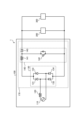
- FIG. 1 is a diagram showing a configuration example of a power conversion device according to a first embodiment
- FIG. 1 is a first diagram showing a configuration example of a power supply unit included in a power conversion device according to a first embodiment
- FIG. 2 is a second diagram showing a configuration example of a power supply unit included in a power conversion device according to the first embodiment
- FIG. 3 is a third diagram showing a configuration example of a power supply unit included in a power conversion device according to embodiment 1;
- FIG. 1 is a diagram showing a configuration example of a power conversion device according to a first embodiment
- FIG. 1 is a first diagram showing a configuration example of a power supply unit included in a power conversion device according to a first embodiment
- FIG. 2 is
- FIG. 1 is a diagram showing an example of a current waveform of a reactor current flowing through a reactor of a power conversion device according to a first embodiment and an example of an FFT (Fast Fourier Transform) analysis result of the reactor current.
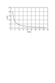
- FIG. 13 is a diagram showing an example of a relationship between a drive frequency of a switching element of a power supply unit included in a power conversion device according to the first embodiment and a current ripple width of a reactor;
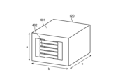
- FIG. 1 is a first diagram illustrating a structure of a reactor used in a power conversion device according to a second embodiment;
- FIG. 2 is a second diagram illustrating a structure of a reactor used in a power conversion device according to a second embodiment.
- FIG. 13 is a diagram showing a configuration example of a refrigeration cycle application device according to a third embodiment.
- Embodiment 1. 1 is a diagram showing a configuration example of a power conversion device 1 according to a first embodiment.
- the power conversion device 1 includes a power supply unit 100, a smoothing unit 200, and a load unit 300.
- the load unit 300 includes a motor, an inverter that drives the motor, and the like.
- the smoothing unit 200 includes a smoothing capacitor, and the like.
- FIG. 2 is a first diagram showing an example of the configuration of the power supply unit 100 provided in the power conversion device 1 according to the first embodiment.
- the power supply unit 100 includes an AC power supply 110, a reactor 120, a rectifier unit 130, and a boost unit 140.
- the rectifier unit 130 and the boost unit 140 form a rectifier boost unit 170.
- the rectifier unit 130 is configured with diodes 131 to 134 connected in a bridge configuration.
- the boost unit 140 has a boost function
- FIG. 2 shows a single-transistor boost chopper circuit composed of a reactor 141, a switching element 142, and a diode 143 as an example.
- the boost unit 140 may be replaced with a step-down unit (not shown) composed of a single-transistor step-down chopper circuit having a step-down function.
- the AC power supply 110 is, for example, a commercial power supply.
- the AC power supply 110 may be outside the power supply unit 100, i.e., outside the power conversion device 1. The same applies hereinafter.
- FIG. 3 is a second diagram showing an example of the configuration of the power supply unit 100 included in the power conversion device 1 according to the first embodiment.
- the power supply unit 100 includes an AC power supply 110, a reactor 120, and a rectifying and boosting unit 150.
- the rectifying and boosting unit 150 is configured to integrate the functions of the rectifying unit 130 and the boosting unit 140 shown in FIG. 2, and is configured as a bridgeless circuit using switching elements 151 to 154, which are four active elements.
- the switching elements 151 to 154 may be configured using four discrete elements, or a module in which the four elements are mounted in the same package may be used.
- FIG. 4 is a third diagram showing a configuration example of the power supply unit 100 provided in the power conversion device 1 according to the first embodiment.
- the power supply unit 100 includes an AC power supply 110, which is a three-phase power supply system, three reactors 120 corresponding to each of the three phases, and a rectification boost unit 160.
- the rectification boost unit 160 is configured to integrate the functions of the rectification unit and the boost unit, and is configured as a converter circuit using six active switching elements 161-166.
- the switching elements 161-166 may be configured using six discrete elements, or a module in which six elements are mounted in the same package may be used.
- a core made of non-oriented electromagnetic steel sheet material, dust-based material, ferrite-based material, or the like is selected according to the application.
- these core materials are often selected mainly according to the drive frequency of the switching element provided in the power supply unit 100 of the power conversion device 1.
- the regions, from low frequency to high frequency, are non-oriented electromagnetic steel sheet material, dust-based material, and ferrite-based material.
- unit price per unit volume the cheapest is non-oriented electromagnetic steel sheet material, dust-based material, and ferrite-based material.
- the size ratio of the reactor 120 in the power supply unit 100 is large. Therefore, in order to miniaturize the power supply unit 100 in the power conversion device 1, it is necessary to miniaturize the reactor 120. In order to miniaturize the reactor 120, it is necessary to PWM drive the power conversion device 1 and increase the drive frequency. By increasing the drive frequency when PWM driving the power conversion device 1, the capacity of the reactor 120 can be reduced, and therefore the volume of the reactor 120 can be reduced. Here, excessively increasing the drive frequency of the power conversion device 1 increases the heat generation density, which raises concerns about thermal destruction of the device. Therefore, in order to increase the drive frequency of the power conversion device 1 to a high frequency, it is necessary to set an appropriate drive frequency and then apply a reactor 120 structure that has low loss and low heat generation.
- Non-PWM driving is a driving state in which current flows through the diode connected in parallel to the switching element shown in Figures 2 to 4 in the power conversion device 1.
- the capacity of the reactor 120 which is based on PWM driving with a high-frequency driving frequency, the current increases sharply during non-PWM driving, and there is a concern that the elements used in the power supply unit 100 in the power conversion device 1 may be damaged.
- the power conversion device 1 is configured to improve the trade-off between the loss of the reactor 120 and the volume of the reactor 120 while providing a reactor 120 with a capacity that takes into account non-PWM driving.
- the power conversion device 1 includes a power supply unit 100 having a rectifier boost unit that has a switching element that can be driven by PWM and converts AC power to DC power, and a reactor 120 that is arranged between an AC power source 110 that supplies AC power and a smoothing unit 200 that smoothes the DC power.
- the capacity of the reactor 120 is set from the reactor peak current that flows through the reactor 120 during non-PWM driving in which a current flows through a diode connected in parallel to the switching element, and the power factor of the power supply unit 100.
- the drive frequency of the switching element provided in the rectifier boost unit is set from the magnetic characteristics of the reactor 120.
- the capacity L of reactor 120 considering non-PWM drive will be described using the current flowing through reactor 120, the power factor of power supply unit 100, etc.
- the capacity of reactor 120 determines the component current. If the capacity of reactor 120 is small, when high power factor control fails in power conversion device 1, that is, when PWM control switches to non-PWM control, the increase in current flowing inside power conversion device 1 is large and heat generation increases, and if no countermeasures are taken, there is a risk of damage to the elements used in power supply unit 100.
- the size of the reactor 120 generally accounts for a large proportion of the power supply, so a large effect can be achieved if the reactor 120 can be miniaturized.
- the control unit responsible for PWM driving of the switching elements will stop.
- the power conversion device 1 will no longer be able to control current using the switching elements, and will enter non-PWM driving, generating a free resonance waveform determined by the capacity of the reactor 120 and the capacity of the capacitor provided in the smoothing unit 200. If the capacity of the capacitor provided in the smoothing unit 200 is sufficiently large, the peak of the free resonance waveform will change depending on the capacity of the reactor 120.
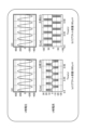
- Figure 5 is a diagram showing the difference in reactor current due to the reactor capacity when a single-phase AC voltage is input in a typical power conversion device.
- Figure 5(a) shows the state when the reactor capacity is 1000 ⁇ H
- Figure 5(b) shows the state when the reactor capacity is 100 ⁇ H.
- the upper figure shows the input voltage to a typical power conversion device
- the lower figure shows the current flowing through the reactor.
- Figure 6 is a diagram showing the difference in reactor current due to the reactor capacity when a three-phase AC voltage is input in a typical power conversion device.
- Figure 6(a) shows the state when the reactor capacity is 1000 ⁇ H
- Figure 6(b) shows the state when the reactor capacity is 100 ⁇ H.
- the power conversion device 1 cannot control the output voltage and control the high power factor of the input current.
- the load unit 300 is a motor load and an inverter driving the motor load, the load unit 300 becomes a constant power load, and therefore, in the power supply unit 100 of the power conversion device 1, the circuit current increases during non-PWM driving compared to during PWM driving due to a decrease in output voltage and an increase in reactive current.
- the increase amount ⁇ I peak of the reactor peak current flowing through the reactor 120 when the power conversion device 1 switches from PWM driving to non-PWM driving is expressed by equation (1).
- Pmax is the maximum output power of the power supply unit 100
- Vref is the DC voltage applied to the smoothing unit 200 connected in parallel to the rectifier boost unit
- pf is the overall power factor of the power supply unit 100
- Vac_peak is the peak value of the input voltage from the AC power supply 110 that supplies AC power.
- the peak value of the line voltage is Vac_peak .
- the relationship between the capacity L of the reactor 120 and the overall power factor pf of the power supply unit 100 is expressed by formula (2).
- a1 is a first coefficient of a defined positive real number
- a2 is a second coefficient of a defined positive real number.
- a1 and a2 are coefficients obtained from the relationship between the capacity L of the reactor 120 and the overall power factor pf of the power supply unit 100 when the power conversion device 1 is not PWM driven. Since a1 and a2 vary depending on the input voltage from the AC power supply 110 and the load power of the load unit 300, it is desirable to obtain them in advance by performing an analysis in accordance with the worst conditions of the actual operation of the power conversion device 1 at the design stage, etc. In the power conversion device 1, an increase in the circuit current of the power supply unit 100 increases the loss of the elements used in the power supply unit 100 and increases heat generation.
- the capacity L of the reactor 120 is set using ⁇ I peak , V ac_peak , P max , V ref , a 1 , and a 2. Specifically, the capacity L of the reactor 120 satisfies the above-mentioned formula (3).
- the power conversion device 1 can prevent damage to the elements of the power supply unit 100 by using the capacity L of the reactor 120 that satisfies formula (3).
- the power conversion device 1 intentionally switches from PWM drive to non-PWM drive, it can prevent damage to the elements of the power supply unit 100 by using the capacity L of the reactor 120 that satisfies formula (3).
- the capacity L of the reactor 120 will be explained, taking into account the non-PWM drive while using the maximum rated current squared time product ⁇ .
- the size ratio of the reactor 120 is generally large, so a great effect can be obtained if the reactor 120 can be miniaturized.
- the power conversion device 1 starts operating in non-PWM drive because power is not supplied to the control unit when starting up or recovering from a sudden stop.
- an inrush current flows as an LC circuit when charging the capacitor in the smoothing unit 200.
- the inrush current flows through the diodes 131-134 of the rectifier 130 constituting the power supply unit 100, the diodes connected in parallel to the switching elements 151-154 if the switching elements 151-154 of the rectifier boost unit 150 are IGBTs, and the diodes connected in parallel to the switching elements 161-166 if the switching elements 161-166 of the rectifier boost unit 160 are IGBTs.
- the current limit of these elements is determined by the maximum rated current squared time product ⁇ [ A2 ⁇ s] based on the current flowing through the power supply unit 100 during non-PWM driving.
- the capacity L of the reactor 120 is derived from the relationship between the circuit constant and the maximum rated current squared time product ⁇ , it is expressed as Equation (4).
- ⁇ is the maximum rated current squared time product based on the current flowing through the power supply unit 100 during non-PWM driving
- L is the capacity of the reactor 120
- C is the capacity of the capacitor that is the smoothing unit 200 connected in parallel to the rectifying boost unit
- Pm is the rated output power of the power supply unit 100
- Vac is the input voltage from the AC power supply 110 that supplies AC power
- a is a derating constant. The derating constant a provides a margin for the maximum rated current squared time product ⁇ .
- the capacitance of the capacitor that is smoothing unit 200 connected in parallel to the rectifying and boosting unit is C
- the rated output power of power supply unit 100 is Pm
- the input voltage from AC power supply 110 that supplies AC power is Vac
- the derating constant is a
- the capacitance L of reactor 120 is set using ⁇ , C, Pm , Vac , and a. Specifically, the capacitance L of reactor 120 satisfies equation (4).
- the power conversion device 1 can prevent damage to the elements of the power supply unit 100 even during non-PWM driving.
- the losses in the reactor 120 include iron loss P_fe and copper loss P_cu.
- Iron loss P_fe is the loss that occurs in the core of the reactor 120
- copper loss P_cu is the loss that occurs in the windings of the reactor 120.
- Iron loss P_fe is expressed by equation (5) from the Steinmetz equation.
- Bm is the maximum magnetic flux density of the reactor 120
- fsw is the driving frequency of the switching element
- k1 , a, and b are constants. Note that for general core materials, a>b.
- Bm is expressed by formula (6) based on the relationship between the capacity L of the reactor 120 and the current ripple width.
- Bm is the maximum magnetic flux density of the reactor 120
- L is the capacity of the reactor 120
- ⁇ i is the current ripple width at the reactor 120
- N is the number of turns of the winding of the reactor 120
- Ae is the cross-sectional area of the reactor 120.
- R dc is the DC component of the winding resistance of reactor 120
- I dc is the DC component of the current flowing through reactor 120
- R ac_f is the AC component of the winding resistance of reactor 120
- I ac is the AC component of the current flowing through reactor 120 .
- FIG. 7 is a diagram showing an example of the current waveform of the reactor current flowing through the reactor 120 of the power conversion device 1 according to the first embodiment and an example of an FFT analysis result of the reactor current.
- the upper diagram shows the current waveform of the reactor current flowing through the reactor 120
- the horizontal axis shows time
- the vertical axis shows current.
- the lower diagram shows the FFT analysis result of the current waveform of the reactor 120 shown in the upper diagram
- the horizontal axis shows frequency
- the vertical axis shows current.
- R dc corresponds to the DC component of the winding resistance shown in FIG. 7
- I dc corresponds to the system frequency component of the current FFT shown in FIG.
- R ac_f corresponds to the AC component of the winding resistance shown in FIG. 7
- I ac corresponds to the carrier frequency component of the current FFT shown in FIG. 7.
- the system frequency component is based on the AC voltage supplied from the AC power supply 110, and is calculated by the DC component of the winding resistance of the reactor 120.
- the carrier frequency component is based on the carrier signal used when the switching element is PWM driven, and is calculated by the AC component of the winding resistance of the reactor 120.
- the AC component current Iac is mainly a triangular waveform ripple component, and can be expressed by equation (8).
- ⁇ i fn is the current ripple width in the reactor 120 when the switching element is PWM driven at the nth drive frequency f swn
- V L is the applied voltage of the reactor 120
- D is the duty ratio when the switching element is PWM driven
- L is the capacity of the reactor 120.
- Equation (10) shows the ratio of the change width of the current ripple width ⁇ i to the change width of the drive frequency fsw .
- ⁇ i f1 is the current ripple width at the first drive frequency f sw1
- ⁇ i f2 is the current ripple width at the second drive frequency f sw2, which is one frequency higher than the first drive frequency f sw1
- X [%] is the ratio of the change width of the current ripple width ⁇ i when the drive frequency f sw of the switching element changes from f sw1 to f sw2 .
- the ratio indicated by X*100 on the left side of formula (10) is 10% or less, there is no significant change in the loss of the reactor 120.
- the current ripple width ⁇ i fn in the reactor 120 when the switching element is PWM driven at the nth drive frequency fswn is calculated by equation (9).
- the drive frequency fsw in the PWM drive of the switching element is set so that X falls within a specified range.
- the drive frequency fsw during PWM driving of the switching elements is set so that the ratio indicated by X*100 is 10% or less.
- the lower limit of the drive frequency fsw during PWM driving of the switching elements is set so as to satisfy the formulas (9) and (10).
- the driving frequency fsw during PWM driving of the switching elements is set so that the iron loss P_fe is greater than the copper loss P_cu with respect to the loss generated in the reactor 120.
- the core loss of the electromagnetic steel sheet core used in the reactor 120 is lower at higher temperatures, so that the increase in loss can be suppressed based on such temperature characteristics.
- the iron loss is ripple width ⁇ driving frequency of the switching elements.
- the ripple width becomes dominant for copper loss according to the I 2 R calculation formula. That is, the higher the driving frequency of the switching elements, the greater the iron loss P_fe becomes than the copper loss P_cu.
- the setting of an upper limit of the drive frequency fsw of the switching element included in the power supply unit 100, taking into consideration the magnetic characteristics of the reactor 120, will be described.
- the size ratio of the reactor 120 is generally large, so a great effect can be obtained if the reactor 120 can be miniaturized.
- the reactor 120 in miniaturizing the reactor 120, if the loss density is not reduced, the reactor 120 will exceed its allowable heat generation and will be damaged, so reducing the loss is important.
- the core material of the reactor 120 is a non-oriented electromagnetic steel sheet material consisting of overlapping thin steel sheets
- the driving frequency fsw of the switching element increases, high-frequency magnetic flux is generated in each steel sheet, causing a skin effect.
- the skin effect is a phenomenon in which, when magnetic flux is generated in a conductor, the density of the magnetic flux is high on the surface of the conductor and decreases as it moves from the surface to the inside.
- the higher the driving frequency fsw of the switching element the more the magnetic flux is concentrated on the surface, and the higher the AC resistance of the conductor becomes. This skin depth t is expressed by equation (11).
- ⁇ is the resistivity of the steel sheet
- ⁇ is the magnetic permeability of the steel sheet
- fsw is the driving frequency of the switching element.
- the drive frequency fsw during PWM drive of the switching elements is set to satisfy equation (12).
- the upper limit of the drive frequency fsw during PWM driving of the switching elements is set so as to satisfy the formula (12).
- a non-oriented electromagnetic steel sheet with a thickness of 0.35 mm and a resistivity of 57*10 -8 ⁇ m is used as the core material of the reactor 120.
- the magnetic permeability is variable depending on the size of the air gap provided in the reactor 120, but for use as a high-frequency reactor, it is about 50 to 100.
- formula (12) is calculated under the above conditions, formula (13) is obtained. From the result of formula (13), it is appropriate to operate the switching element at a driving frequency f sw of about 10 kHz.
- the power conversion device 1 includes, as the power supply unit 100, a rectifier boost unit having a PWM-driveable switching element, and a reactor 120.
- the capacity L of the reactor 120 is set from the reactor peak current flowing through the reactor 120 and the power factor of the power conversion device 1 during non-PWM drive in which a current flows through a diode connected in parallel to the switching element.
- the drive frequency fsw of the switching element included in the rectifier boost unit is set from the magnetic characteristics of the reactor 120. This makes it possible for the power conversion device 1 to prevent damage to elements used in power conversion when the PWM-driveable switching element is not PWM-driven.
- Embodiment 2 In the second embodiment, a description will be given of constraints on the structure of the reactor 120. Note that in the second embodiment, the configuration of the power conversion device 1 is similar to the configuration of the power conversion device 1 shown in Figs. 1 to 4.
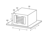
- FIG. 9 is a first diagram that illustrates a structure of a reactor 120 used in a power conversion device 1 according to a second embodiment.
- increasing the driving frequency fsw of the switching element is effective for miniaturizing the power conversion device 1, but increasing the driving frequency fsw of the switching element has a trade-off relationship between loss and heat generation.
- a structure of a reactor 120 that can suppress loss and heat generation of a core 401 of the reactor 120 in order to improve the trade-off relationship between loss and heat generation will be described.
- the shape of the core 401 consisting of three legs is, for example, an EE core or an EI core.
- the reactor 120 has a shell-type structure in which the winding 402 is arranged in the central leg and the core 401 exists so as to surround the winding 402.
- the aspect ratio of the core 401 of the reactor 120 is set to increase in the order of a ⁇ b ⁇ c.
- a is the height
- b is the width
- c is the depth.
- the reactor 120 by configuring the reactor 120 as shown in FIG. 9, it is possible to configure the size of the reactor 120 to be smaller when the number of turns of the winding 402 is the same with the same effective cross-sectional area.
- the reactor 120 By configuring the reactor 120 to have the lowest possible height, i.e., to be small, the reactor 120 can efficiently dissipate heat from the center of the core 401, which is the most difficult place to dissipate heat.
- FIG. 10 is a second diagram that shows a schematic structure of the reactor 120 used in the power conversion device 1 according to the second embodiment.
- the reactor 120 shown in FIG. 10 is obtained by mounting a heat sink 403 on the core 401 of the reactor 120 shown in FIG. 9.
- the heat sink 403 is a metal plate and serves as a base for the core 401.
- the reason for making the shape of the core 401 of the reactor 120 in the order of width ⁇ depth is to reduce the volume of the core 401 with the same effective cross-sectional area. If the width is increased to obtain the same effective cross-sectional area, the outer legs of the core 401 must be expanded outward in order to maintain the same space factor of the winding 402, and the total volume of the core 401 increases.
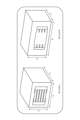
- Figure 11 is a comparative example showing the difference in volume when the effective cross-sectional area is the same for reactors of the same height with width ⁇ depth and width > depth. Considering the same winding space factor, the outer core frame becomes larger, so as shown in Figure 11, a reactor with width ⁇ depth can be constructed that is more compact and has lower loss.
- the reactor 120 has the shape of a three-legged core 401, the winding 402 is present on the central leg of the core 401, the core 401 surrounds the winding 402, and the aspect ratio of the core 401 when the core window is facing forward is such that the width is greater than the height, and the depth is greater than the width. Furthermore, the core 401 of the reactor 120 is in contact with the heat sink 403, i.e., a metal plate that serves as a base, and the metal plate is in contact with the product to which the power conversion device 1 is applied.
- the heat sink 403 which is a metal plate, so that it is in contact with the cover of the housing of the air conditioner, the reactor 120 can further improve its heat dissipation effect.
- FIG. 12 is a diagram showing a configuration example of a refrigeration cycle-applied device 900 according to a third embodiment.
- the refrigeration cycle-applied device 900 according to the third embodiment includes the power conversion device 1 described in the first embodiment.
- the refrigeration cycle-applied device 900 according to the third embodiment can be applied to products including a refrigeration cycle, such as air conditioners, refrigerators, freezers, and heat pump water heaters.
- a refrigeration cycle such as air conditioners, refrigerators, freezers, and heat pump water heaters.
- components having the same functions as those in the first embodiment are given the same reference numerals as those in the first embodiment.
- the load unit 300 included in the power conversion device 1 includes a motor.
- the motor 916 is placed outside the power conversion device 1 due to the configuration in which the motor 916 is included in the compressor 914.
- the refrigeration cycle application device 900 includes a compressor 914, a four-way valve 902, an indoor heat exchanger 906, an expansion valve 908, and an outdoor heat exchanger 910, which are attached via refrigerant piping 912.
- a compression mechanism 904 that compresses the refrigerant
- a motor 916 that operates the compression mechanism 904.
- the refrigeration cycle device 900 can perform heating or cooling operation by switching the four-way valve 902.
- the compression mechanism 904 is driven by a variable speed controlled motor 916.
- the refrigerant is pressurized by the compression mechanism 904 and sent out, passes through the four-way valve 902, the indoor heat exchanger 906, the expansion valve 908, the outdoor heat exchanger 910, and the four-way valve 902, and returns to the compression mechanism 904.
- the refrigerant is pressurized by the compression mechanism 904 and sent out, passes through the four-way valve 902, the outdoor heat exchanger 910, the expansion valve 908, the indoor heat exchanger 906, and the four-way valve 902, and returns to the compression mechanism 904.
- the indoor heat exchanger 906 acts as a condenser to release heat, and the outdoor heat exchanger 910 acts as an evaporator to absorb heat.
- the outdoor heat exchanger 910 acts as a condenser to release heat, and the indoor heat exchanger 906 acts as an evaporator to absorb heat.
- the expansion valve 908 reduces the pressure of the refrigerant to expand it.
- 1 Power conversion device 100 Power supply unit, 110 AC power supply, 120, 141 Reactor, 130 Rectification unit, 131-134, 143 Diode, 140 Boost unit, 142, 151-154, 161-166 Switching elements, 150, 160, 170 Rectification boost unit, 200 Smoothing unit, 300 Load unit, 401 Core, 402 Winding, 403 Heat sink, 900 Refrigeration cycle applicable device, 902 Four-way valve, 904 Compression mechanism, 906 Indoor heat exchanger, 908 Expansion valve, 910 Outdoor heat exchanger, 912 Refrigerant piping, 914 Compressor, 916 Motor.
Landscapes
- Engineering & Computer Science (AREA)
- Power Engineering (AREA)
- Dc-Dc Converters (AREA)
Priority Applications (2)
| Application Number | Priority Date | Filing Date | Title |
|---|---|---|---|
| JP2025529356A JPWO2025004327A1 (cg-RX-API-DMAC7.html) | 2023-06-30 | 2023-06-30 | |
| PCT/JP2023/024382 WO2025004327A1 (ja) | 2023-06-30 | 2023-06-30 | 電力変換装置および冷凍サイクル適用機器 |
Applications Claiming Priority (1)
| Application Number | Priority Date | Filing Date | Title |
|---|---|---|---|
| PCT/JP2023/024382 WO2025004327A1 (ja) | 2023-06-30 | 2023-06-30 | 電力変換装置および冷凍サイクル適用機器 |
Publications (1)
| Publication Number | Publication Date |
|---|---|
| WO2025004327A1 true WO2025004327A1 (ja) | 2025-01-02 |
Family
ID=93938046
Family Applications (1)
| Application Number | Title | Priority Date | Filing Date |
|---|---|---|---|
| PCT/JP2023/024382 Ceased WO2025004327A1 (ja) | 2023-06-30 | 2023-06-30 | 電力変換装置および冷凍サイクル適用機器 |
Country Status (2)
| Country | Link |
|---|---|
| JP (1) | JPWO2025004327A1 (cg-RX-API-DMAC7.html) |
| WO (1) | WO2025004327A1 (cg-RX-API-DMAC7.html) |
Citations (4)
| Publication number | Priority date | Publication date | Assignee | Title |
|---|---|---|---|---|
| JP2007215385A (ja) * | 2006-02-13 | 2007-08-23 | Mitsubishi Electric Corp | 直流電源装置 |
| JP2009089469A (ja) * | 2007-09-28 | 2009-04-23 | Hitachi Appliances Inc | コンバータ装置及びモジュール |
| JP2017055581A (ja) * | 2015-09-10 | 2017-03-16 | ジョンソンコントロールズ ヒタチ エア コンディショニング テクノロジー(ホンコン)リミテッド | 直流電源装置および空気調和機 |
| JP2022050131A (ja) * | 2020-09-17 | 2022-03-30 | パナソニック株式会社 | 電力変換装置、電力変換装置の制御方法、及び電力システム |
Family Cites Families (2)
| Publication number | Priority date | Publication date | Assignee | Title |
|---|---|---|---|---|
| JP6751683B2 (ja) * | 2017-03-28 | 2020-09-09 | 株式会社日立製作所 | 電力変換装置および電力変換方法 |
| US20230378867A1 (en) * | 2020-10-26 | 2023-11-23 | Mitsubishi Electric Corporation | Power conversion apparatus, motor drive apparatus, and refrigeration cycle apparatus |
-
2023
- 2023-06-30 JP JP2025529356A patent/JPWO2025004327A1/ja active Pending
- 2023-06-30 WO PCT/JP2023/024382 patent/WO2025004327A1/ja not_active Ceased
Patent Citations (4)
| Publication number | Priority date | Publication date | Assignee | Title |
|---|---|---|---|---|
| JP2007215385A (ja) * | 2006-02-13 | 2007-08-23 | Mitsubishi Electric Corp | 直流電源装置 |
| JP2009089469A (ja) * | 2007-09-28 | 2009-04-23 | Hitachi Appliances Inc | コンバータ装置及びモジュール |
| JP2017055581A (ja) * | 2015-09-10 | 2017-03-16 | ジョンソンコントロールズ ヒタチ エア コンディショニング テクノロジー(ホンコン)リミテッド | 直流電源装置および空気調和機 |
| JP2022050131A (ja) * | 2020-09-17 | 2022-03-30 | パナソニック株式会社 | 電力変換装置、電力変換装置の制御方法、及び電力システム |
Also Published As
| Publication number | Publication date |
|---|---|
| JPWO2025004327A1 (cg-RX-API-DMAC7.html) | 2025-01-02 |
Similar Documents
| Publication | Publication Date | Title |
|---|---|---|
| CN104702107B (zh) | 转换器电路、电动机驱动控制装置、空气调节器、冰箱 | |
| KR101317107B1 (ko) | 스위칭 전원 회로 | |
| JP3687641B2 (ja) | インバ−タエアコン | |
| KR20130067440A (ko) | 공기 조화기, 이의 제어 장치 및 제어 방법 | |
| WO2014103745A1 (ja) | 昇圧回路、モータ駆動モジュール及び冷凍機器 | |
| US11482920B2 (en) | Single stage, two level pulse width modulation strategies for active harmonic filters | |
| WO2016098160A1 (ja) | 電力変換装置、圧縮機、送風機、および空気調和機 | |
| KR102579780B1 (ko) | 전력 변환 장치 및 이를 포함하는 공기 조화기 | |
| JPH0833392A (ja) | 空気調和機 | |
| EP3121525B1 (en) | Power conversion apparatus and air conditioner including the same | |
| KR101982717B1 (ko) | 전력 변환 장치 | |
| JP4722541B2 (ja) | 電源装置およびこれを用いた空気調和機 | |
| WO2025120777A1 (ja) | 電力変換装置、モータ駆動装置及び冷凍サイクル適用機器 | |
| WO2025120780A1 (ja) | 電力変換装置、モータ駆動装置および冷凍サイクル適用機器 | |
| WO2025181941A1 (ja) | 電力変換装置、モータ駆動装置および冷凍サイクル適用機器 | |
| WO2025169405A1 (ja) | 電力変換装置、モータ駆動装置および冷凍サイクル適用機器 | |
| AU2013270449A1 (en) | Converter circuit and motor drive control apparatus, air-conditioner, refrigerator, and induction heating cooker provided with the circuit | |
| JP2011135668A (ja) | インバータ装置 |
Legal Events
| Date | Code | Title | Description |
|---|---|---|---|
| 121 | Ep: the epo has been informed by wipo that ep was designated in this application |
Ref document number: 23943716 Country of ref document: EP Kind code of ref document: A1 |
|
| ENP | Entry into the national phase |
Ref document number: 2025529356 Country of ref document: JP Kind code of ref document: A |
|
| WWE | Wipo information: entry into national phase |
Ref document number: 2025529356 Country of ref document: JP |
|
| NENP | Non-entry into the national phase |
Ref country code: DE |
|
| 122 | Ep: pct application non-entry in european phase |
Ref document number: 23943716 Country of ref document: EP Kind code of ref document: A1 |