WO2024262547A1 - 高炉の操業方法 - Google Patents
高炉の操業方法 Download PDFInfo
- Publication number
- WO2024262547A1 WO2024262547A1 PCT/JP2024/022266 JP2024022266W WO2024262547A1 WO 2024262547 A1 WO2024262547 A1 WO 2024262547A1 JP 2024022266 W JP2024022266 W JP 2024022266W WO 2024262547 A1 WO2024262547 A1 WO 2024262547A1
- Authority
- WO
- WIPO (PCT)
- Prior art keywords
- blast furnace
- gas
- temperature
- tuyere
- amount
- Prior art date
- Legal status (The legal status is an assumption and is not a legal conclusion. Google has not performed a legal analysis and makes no representation as to the accuracy of the status listed.)
- Ceased
Links
Images




Classifications
-
- C—CHEMISTRY; METALLURGY
- C21—METALLURGY OF IRON
- C21B—MANUFACTURE OF IRON OR STEEL
- C21B5/00—Making pig-iron in the blast furnace
- C21B5/001—Injecting additional fuel or reducing agents
-
- C—CHEMISTRY; METALLURGY
- C21—METALLURGY OF IRON
- C21B—MANUFACTURE OF IRON OR STEEL
- C21B5/00—Making pig-iron in the blast furnace
-
- C—CHEMISTRY; METALLURGY
- C21—METALLURGY OF IRON
- C21B—MANUFACTURE OF IRON OR STEEL
- C21B5/00—Making pig-iron in the blast furnace
- C21B5/06—Making pig-iron in the blast furnace using top gas in the blast furnace process
-
- C—CHEMISTRY; METALLURGY
- C21—METALLURGY OF IRON
- C21B—MANUFACTURE OF IRON OR STEEL
- C21B7/00—Blast furnaces
- C21B7/002—Evacuating and treating of exhaust gases
-
- C—CHEMISTRY; METALLURGY
- C21—METALLURGY OF IRON
- C21B—MANUFACTURE OF IRON OR STEEL
- C21B5/00—Making pig-iron in the blast furnace
- C21B5/001—Injecting additional fuel or reducing agents
- C21B2005/005—Selection or treatment of the reducing gases
-
- C—CHEMISTRY; METALLURGY
- C21—METALLURGY OF IRON
- C21B—MANUFACTURE OF IRON OR STEEL
- C21B2100/00—Handling of exhaust gases produced during the manufacture of iron or steel
- C21B2100/20—Increasing the gas reduction potential of recycled exhaust gases
- C21B2100/28—Increasing the gas reduction potential of recycled exhaust gases by separation
Definitions
- the present invention relates to a method for operating a blast furnace.
- This application claims priority based on Japanese Patent Application No. 2023-101584, filed on June 21, 2023, the contents of which are incorporated herein by reference.
- the blast furnace process is the mainstream of pig iron manufacturing processes.
- ferrous raw materials raw materials containing iron oxide, mainly sintered ore, hereafter also referred to simply as "ferrous raw materials”
- coke are charged alternately and in layers into the blast furnace from the top of the furnace, while hot air is blown into the blast furnace from tuyere holes installed in the lower part of the blast furnace below the bosh.
- the hot air reacts with the pulverized coal blown in together with the hot air and the coke in the blast furnace to generate high-temperature reducing gas (mainly CO gas in this case).
- high-temperature reducing gas mainly CO gas in this case
- the reducing gas rises in the blast furnace, heating and reducing the ferrous raw materials.
- the ferrous raw materials descend in the blast furnace, while being heated and reduced by the reducing gas.
- the ferrous raw materials then melt and drip into the blast furnace while being further reduced by the coke.
- the iron-based raw materials are eventually stored in the hearth as molten pig iron (pig iron) containing just under 5% by mass of carbon.
- the molten pig iron in the hearth is removed from the tap hole and used in the next steelmaking process. Therefore, in the blast furnace process, carbonaceous materials such as coke and pulverized coal are used as reducing agents.
- CO2 gas carbon dioxide
- the blast furnace process uses carbonaceous materials as a reducing agent, which generates a large amount of CO2 gas. Therefore, the steel industry is one of the major industries in terms of CO2 gas emissions, and must respond to this social demand. Specifically, there is an urgent need to further reduce the reducing agent ratio (amount of reducing agent used per ton of molten iron) in blast furnace operation.
- the reducing agent has the role of raising the temperature of the charge by becoming heat in the furnace and the role of reducing the iron-based raw materials in the furnace, and in order to reduce the reducing agent ratio, it is necessary to increase the reduction efficiency in the furnace.
- the reduction reaction in the furnace can be expressed by various reaction formulas. Among these reduction reactions, the direct reduction reaction by coke (reaction formula: FeO + C ⁇ Fe + CO) is an endothermic reaction accompanied by a large heat absorption. Therefore, it is important to prevent this reaction from occurring as much as possible in reducing the reducing agent ratio.
- this direct reduction reaction occurs in the lower part of the blast furnace, if the iron-based raw materials can be sufficiently reduced by reducing gas such as CO and H2 before they reach the lower part of the furnace, the iron-based raw materials that are the subject of the direct reduction reaction can be reduced.
- Patent Document 1 As a conventional technique for solving the above problems, for example, as disclosed in Patent Document 1, a technique is known in which hydrogen gas is blown in together with hot air from the tuyere to improve the reducing gas potential inside the furnace. In this technique, hydrogen gas is used as a reducing gas for the iron-based raw material, thereby reducing the reducing agent ratio.
- the present inventors have defined a parameter called the reduction rate of carbon consumption intensity (Input ⁇ C) as a parameter serving as an index for reducing the reducing agent ratio.
- Carbon consumption intensity (Input C) is the carbon required to produce one ton of molten iron (i.e., the carbon consumption per ton of molten iron).
- the inventors of the present invention have studied the technology described in Patent Document 1 in detail, and have found that when trying to increase Input ⁇ C by the technology described in Patent Document 1, it is necessary to heat a large amount of hydrogen gas to a high temperature and inject it into the blast furnace. For example, when trying to make Input ⁇ C 40% or more, it is necessary to make the injection amount of hydrogen gas 650 Nm 3 /t or more and the temperature of the hydrogen gas 1200° C. or more. In this case, in addition to the need to prepare a large amount of hydrogen gas, it is necessary to prepare a heating device for heating the hydrogen gas to a high temperature and to construct the blast furnace equipment from a material that can withstand high-temperature hydrogen gas.
- Patent Document 1 had the problem that it required a great deal of effort to increase Input ⁇ C.
- the present invention has been made in consideration of the above problems, and the object of the present invention is to provide a method of operating a blast furnace that can increase Input ⁇ C even when the amount of hydrogen-based reducing gas (details of hydrogen-based reducing gas will be described later) injected is reduced and the heating temperature of the hydrogen-based reducing gas is lowered.
- the object of the present invention is to provide a method of operating a blast furnace that can increase Input ⁇ C even when the amount of hydrogen-based reducing gas (details of hydrogen-based reducing gas will be described later) injected is reduced and the heating temperature of the hydrogen-based reducing gas is lowered.
- the inventors have studied the technology described in Patent Document 1 in detail and found that a large amount of hydrogen gas is discharged as top exhaust gas during blast furnace operation.
- the inventors therefore attempted to separate reducing gas (this reducing gas includes hydrogen gas and CO gas) from the top exhaust gas and inject the separated reducing gas into the blast furnace.
- this reducing gas includes hydrogen gas and CO gas
- the inventors found that even when the amount of hydrogen gas injected was reduced compared to the technology described in Patent Document 1 and the heating temperature of the hydrogen gas was lowered, an Input ⁇ C equivalent to that of the technology described in Patent Document 1 could be obtained.
- the present invention was made based on this knowledge.
- the gist of the present invention is as follows. (1) a step of heating a hydrogen-based reducing gas supplied from outside a blast furnace system; injecting the heated hydrogen-based reducing gas into a blast furnace; separating the reducing gas from the top exhaust gas; heating the separated reducing gas; and injecting the reducing gas into the blast furnace. (2) The method for operating a blast furnace according to (1), characterized in that the reducing gas is injected into the blast furnace from a normal tuyere provided in a lower part of the blast furnace. (3) The method for operating a blast furnace according to (1) or (2), characterized in that the reducing gas is injected into a shaft portion of the blast furnace.
- the Input ⁇ C can be increased even if the amount of hydrogen-based reducing gas injected is reduced and the heating temperature of the hydrogen-based reducing gas is lowered.
- FIG. 1 is a flow diagram showing an overall configuration of a blast furnace system used in this embodiment.
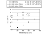
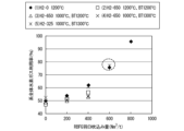
- 6 is a graph verifying the effect of the first embodiment.
- 11 is a graph verifying the effect of the second embodiment.
- 11 is a graph verifying the effect of the second embodiment.
- 11 is a graph verifying the effect of the second embodiment.
- 11 is a graph verifying the effect of the second embodiment.
- 11 is a graph verifying the effect of the second embodiment.
- the blast furnace system 1 includes a blast furnace 10, a CO2 separation and capture device 20, a buffer tank 30, a compressor 40, a heater 50, and flow meters 61 and 62.
- the blast furnace 10 includes a blast furnace body 10a, a normal tuyere 11, and a shaft tuyere 12. Inside the blast furnace body 10a, a reduction reaction of the iron-based raw materials occurs by the blast furnace method. Specifically, the iron-based raw materials and coke are charged alternately and in layers into the blast furnace 10 from the top of the blast furnace 10, while hot air, pulverized coal, and enriched oxygen gas are blown into the blast furnace 10 from the normal tuyere 11.
- the "tuyere tip combustion temperature” means the temperature at the gas outlet of the normal tuyere 11.
- the hot air reacts with the pulverized coal blown in together with the hot air and the coke in the blast furnace 10 to generate high-temperature reducing gas (mainly CO gas in this case).
- high-temperature reducing gas mainly CO gas in this case.
- the hot air gas ifies the coke and pulverized coal.
- the reducing gas rises inside the blast furnace 10 and reduces the iron-based raw materials while heating them.
- the iron-based raw materials are heated and reduced by reducing gas while descending through the blast furnace 10.
- the iron-based raw materials then melt and drip through the blast furnace 10 while being further reduced by coke.
- the iron-based raw materials are ultimately stored in the hearth as molten pig iron (pig iron) containing just under 5% by mass of carbon.
- the molten pig iron in the hearth is removed from the tap hole and used in the next steelmaking process.
- the normal tuyere 11 is installed below the bosh of the blast furnace 10, and in addition to the hot air described above, as described below, heated hydrogen-based reducing gas and reducing gas separated from the top exhaust gas (blast furnace exhaust gas) are blown into the blast furnace 10. Note that while normal tuyere 11 is shown in two locations, one on the left and one on the right, in FIG. 1, three or more tuyere may be installed around the entire circumference of the blast furnace 10, spaced apart at a predetermined pitch.
- the shaft tuyere 12 is provided at a higher position than the normal tuyere 11 of the blast furnace 10, and injects the reducing gas separated from the top exhaust gas into the shaft 10b of the blast furnace 10.
- the shaft tuyere 12 is depicted in two places on the left and right of the shaft 10b in FIG. 1, three or more may be attached at a predetermined pitch around the entire circumference of the blast furnace 10.
- the shaft tuyere 12 is depicted in FIG. 1 on the shaft 10b, it may be attached to the belly, bosch, or lower position, which is lower than the shaft 10b, as long as it can inject the reducing gas separated from the top exhaust gas into the shaft 10b and is higher than the installation position of the normal tuyere 11.
- the CO2 separation and capture device 20 is a device that recovers the top flue gas and separates it into reducing gas (CO gas and hydrogen gas) and nitrogen gas, and CO2 gas and H2O gas.
- the separation method is not particularly limited, and examples thereof include chemical adsorption and physical adsorption (PSA).
- PSA chemical adsorption and physical adsorption
- the reducing gas and nitrogen gas separated from the top flue gas are also referred to as RBFG (Returned Blast Furnace Gas).
- RBFG Returned Blast Furnace Gas
- CO2 gas and H2O gas are discharged outside the system.
- the CO2 separation and capture device 20 does not necessarily recover the entire amount of the top flue gas.
- the CO2 separation and capture device 20 may recover only the amount of top flue gas corresponding to the flow rate of RBFG injected into the blast furnace.
- the buffer tank 30 is a tank that temporarily stores RBFG. A desired amount of RBFG is introduced from the buffer tank 30 to the compressor 40. The remaining RBFG is used, for example, as a heat source in a steelworks.
- the compressor 40 pressurizes the RBFG.
- the compressor 40 pressurizes the RBFG to, for example, the internal pressure of the blast furnace 10 (approximately 4.5 atmospheres).
- the pressurized RBFG is introduced into the heater 50.
- the heater 50 heats the RBFG.
- the heating temperature is set arbitrarily according to the operating conditions of the blast furnace 10, but for example, when the RBFG is blown into the shaft 10b of the blast furnace 10 from the shaft tuyere 12, it is preferable to set it to 800°C or higher.
- the heater 50 can be sufficiently realized by an electric heater or the like.
- the RBFG heated by the heater 50 is blown into the blast furnace 10, for example, from the normal tuyere 11, or blown into the shaft 10b of the blast furnace 10 from the shaft tuyere 12. In FIG.
- the RBFG is blown into the blast furnace 10 from the normal tuyere 11 and the shaft tuyere 12 on the left side, but the RBFG may also be blown into the blast furnace 10 from the normal tuyere 11 and the shaft tuyere 12 on the right side.
- the RBFG may be blown into the blast furnace 10 from both the normal tuyere 11 and the shaft tuyere 12.
- the flow meter 61 normally measures the flow rate of RBFG injected into the blast furnace 10 from the tuyere 11.
- the flow meter 62 measures the flow rate of RBFG injected into the shaft section 10b of the blast furnace 10 from the shaft section tuyere 12.
- by adjusting the flow rate of RBFG introduced from the buffer tank 30 to the compressor 40 it is possible to arbitrarily adjust the flow rate of RBFG injected into the blast furnace 10 from the tuyere 11 and the flow rate of RBFG injected into the shaft section 10b of the blast furnace 10 from the shaft section tuyere 12.
- the hydrogen-based reducing gas supply system 2 includes a hydrogen-based reducing gas tank 70, a heater 71, and a flow meter 72.
- the hydrogen-based reducing gas supply system 2 is a system that supplies hydrogen-based reducing gas to the blast furnace system 1 from outside the blast furnace system 1.
- the hydrogen-based reducing gas tank 70 is a tank for storing hydrogen-based reducing gas.
- the hydrogen-based reducing gas is a concept including hydrogen gas as well as a mixed gas of hydrogen gas and other gases (such as nitrogen gas) (which do not impair the effect of this embodiment).
- the heater 71 heats the hydrogen-based reducing gas supplied from the hydrogen-based reducing gas tank 70.
- the heater 71 can be sufficiently realized by an electric heater or the like.
- the heater 71 is normally connected to the tuyere 11, and the heated hydrogen-based reducing gas is normally blown into the blast furnace 10 from the tuyere 11.
- the heater 71 may be used in combination with the heater 50.
- the flowmeter 72 measures the flow rate of the hydrogen-based reducing gas blown into the blast furnace 10 from the tuyere 11.
- the Input ⁇ C can be increased.
- the hydrogen-based reducing gas is normally injected from the tuyere 11, but the hydrogen-based reducing gas may also be injected into the blast furnace 10 from the shaft tuyere 12.
- the operation method of the blast furnace 10 according to the first embodiment is generally as follows. That is, iron-based raw materials and coke are charged alternately and in layers into the blast furnace 10 from the top of the blast furnace 10, while heated hydrogen-based reducing gas is supplied from the hydrogen-based reducing gas supply system 2 to the normal tuyere 11. Then, hot air, pulverized coal, enriched oxygen gas, heated hydrogen-based reducing gas, and RBFG containing heated CO and H 2 are blown into the blast furnace 10 from the normal tuyere 11. The hot air reacts with the pulverized coal blown in together with the hot air and the coke in the blast furnace 10 to generate high-temperature reducing gas (mainly CO gas here).
- high-temperature reducing gas mainly CO gas here.
- the hot air gas ifies the coke and pulverized coal.
- the reducing gas rises in the blast furnace 10 and reduces the iron-based raw materials while heating them.
- the hydrogen-based reducing gas and RBFG rise in the blast furnace 10 and reduce the iron-based raw materials while heating them.
- the iron-based raw materials are heated and reduced by reducing gas, hydrogen-based reducing gas, and RBFG while descending through the blast furnace 10.
- the iron-based raw materials are then melted and dripped through the blast furnace 10 while being further reduced by coke.
- the iron-based raw materials are finally stored in the hearth as molten pig iron (pig iron) containing slightly less than 5% by mass of carbon.
- the molten pig iron in the hearth is removed from a tap hole and is used in the next steelmaking process.
- the CO2 separation and capture device 20 recovers the top flue gas and separates it into reducing gas (CO gas and hydrogen gas) and nitrogen gas (i.e., RBFG) and CO2 gas and H2O gas.
- the CO2 gas and H2O gas are discharged outside the system.
- RBFG is temporarily stored in the buffer tank 30.
- a desired amount of RBFG is introduced from the buffer tank 30 into the compressor 40.
- the remaining RBFG is discharged outside the system and used, for example, as a heat source in a steelworks.
- the RBFG is then pressurized by the compressor 40.
- the compressor 40 pressurizes the RBFG to, for example, the internal pressure of the blast furnace 10 (approximately 4.5 atmospheres).
- the pressurized RBFG is introduced into the heater 50.
- the RBFG is then heated by the heater 50.
- the heating temperature is set arbitrarily depending on the operating conditions of the blast furnace 10.
- the RBFG heated by the heater 50 is blown into the blast furnace 10 from the normal tuyere 11.
- the flowmeter 61 measures the flow rate of the RBFG blown into the blast furnace 10 from the normal tuyere 11.
- the RBFG is mainly blown into the blast furnace 10 from the normal tuyere 11, but may also be blown into the blast furnace 10 from the shaft tuyere 12 as an auxiliary. Details will be described later.
- the tuyere combustion temperature is preferably maintained at about 2000 to 2300°C
- the furnace top exhaust gas temperature is preferably maintained at about 105°C or higher
- the molten iron temperature is preferably maintained at about 1520°C or higher.
- the upper limit value of the tuyere combustion temperature is an upper limit value assuming normal operation (operation without injection of hydrogen-based reducing gas or RBFG).
- the tuyere combustion temperature exceeds the upper limit value, it is preferable to take measures such as strengthening the cooling capacity of the tuyere equipment to prevent wear and tear on the tuyere equipment and using materials with higher heat resistance. It is preferable to determine the specifications of the blast furnace operation so that the tuyere combustion temperature, furnace top exhaust gas temperature, and molten iron temperature are maintained within a specified range. As long as the tuyere combustion temperature, furnace top exhaust gas temperature, and molten iron temperature are maintained within the specified ranges, the blast furnace operation specifications can be freely designed. Also, although the tuyere combustion temperature may exceed the upper limit as a result of the design, it is preferable to take the above-mentioned measures separately.
- the blowing temperature of the hydrogen-based reducing gas (the temperature of the hydrogen-based reducing gas usually blown from the tuyere 11) is preferably about 800 to 1000°C, and the blowing amount of hydrogen gas in the hydrogen-based reducing gas is preferably about 300 to 600 Nm 3 /t. Both are in a range lower than that of Patent Document 1.
- the blowing temperature of the RBFG (the temperature of the RBFG usually blown from the tuyere 11, i.e., the heating temperature by the heater 50) is preferably about 800 to 1000°C, and the blowing amount of the RBFG is preferably about 400 to 800 Nm 3 /t.
- the blowing amount of the RBFG is preferably 600 Nm 3 /t or more.
- Input ⁇ C exceeds 40%.
- Other adjustable parameters include the blowing amount of hot air, the amount of oxygen contained in the hot air (the blowing amount of oxygen), etc.
- the molten pig iron temperature can also be adjusted by the amount of pulverized coal injected into the blast furnace 10 or the coke ratio (the amount of coke used per ton of molten pig iron). For example, the molten pig iron temperature is first adjusted by the amount of pulverized coal injected, and if the molten pig iron temperature exceeds a predetermined range even when the amount of pulverized coal injected becomes zero, the coke ratio is adjusted.
- the molten pig iron temperature is a value that reflects the total heat (furnace heat) in the blast furnace 10.
- the tuyere combustion temperature, the top exhaust gas temperature, and the hot metal temperature are monitored periodically (preferably all the time), and if any of the tuyere combustion temperature, the top exhaust gas temperature, and the hot metal temperature falls outside the above-mentioned range, the operating conditions (for example, as described above, at least one of the hydrogen-based reducing gas blowing temperature, the amount of hydrogen gas blown in the hydrogen-based reducing gas, the RBFG blowing temperature, the RBFG blowing amount, the hot blast blowing amount, and the amount of oxygen contained in the hot blast (the amount of enriched oxygen gas blown)) can be adjusted.
- the tuyere combustion temperature, the top exhaust gas temperature, and the hot metal temperature are prone to fluctuate when blowing hydrogen-based reducing gas or RBFG, it is preferable to monitor the tuyere combustion temperature, the top exhaust gas temperature, and the hot metal temperature when blowing these gases.
- This blast furnace mathematical model is, in outline, a plurality of meshes (small regions) defined by dividing the internal region of the blast furnace in the height direction, radial direction, and circumferential direction, and the behavior of each mesh is simulated.
- the prerequisites for the simulation are as follows. ⁇ Hydrogen gas is used as the hydrogen-based reducing gas.
- the CO2 separation and capture device 20 separates and removes 100% of the CO2 gas and H2O gas contained in the top flue gas. -
- the amount of molten iron produced and the temperature of molten iron will be constant at all levels (12,350 t/d, 1,535°C).
- the top exhaust gas temperature is set near the lower limit (105°C).
- Furnace heat adjustment (adjustment of molten iron temperature) is performed by adjusting the amount of pulverized coal injected. If the molten iron temperature exceeds 1535°C even when the amount of pulverized coal injected becomes zero, the coke rate is adjusted. The amount of hot air and the amount of oxygen blown were adjusted so as to satisfy the above prerequisites.
- Levels 1 to 5 correspond to the first embodiment.
- Level 1-1 No hydrogen gas blowing, hot air blowing temperature of 1200°C, RBFG blowing operation (blow temperature of 1200°C) (H2-0 BT1200°C in Figures 2 and 3.
- H2-0 BT1200°C indicates that no hydrogen gas blowing and hot air blowing temperature of 1200°C.
- Level 1-2 With hydrogen gas blowing (blowing temperature 1200°C, blowing rate 650 Nm 3 /t), hot air blowing temperature 1200°C, RBFG blowing operation (blowing temperature 1000°C) (H2-650 1200°C, BT 1200°C in Figures 2 and 3.
- H2-650 1200°C indicates that the hydrogen gas blowing rate is 650 Nm 3 /t and the blowing temperature is 1200°C
- BT 1200°C indicates that the hot air blowing temperature is 1200°C.
- Level 1-3 With hydrogen gas blowing (blowing temperature 1000°C, blowing rate 650 Nm 3 /t), hot air blowing temperature 1200°C, RBFG blowing operation (blowing temperature 1000°C) (H2-650 1000°C, BT 1200°C in Figures 2 and 3.
- H2-650 1000°C indicates that the hydrogen gas blowing rate is 650 Nm 3 /t and the blowing temperature is 1000°C
- BT 1200°C indicates that the hot air blowing temperature is 1200°C.
- Level 1-4 With hydrogen gas blowing (blowing temperature 1000°C, blowing rate 650 Nm 3 /t), hot air blowing temperature 1300°C, RBFG blowing operation (blowing temperature 1000°C) (H2-650 1000°C, BT 1300°C in Figures 2 and 3.
- H2-650 1000°C indicates that the hydrogen gas blowing rate is 650 Nm 3 /t and the blowing temperature is 1000°C
- BT 1300°C indicates that the hot air blowing temperature is 1300°C.
- Level 1-5 With hydrogen gas blowing (blowing temperature 1000°C, blowing rate 325 Nm 3 /t), hot air blowing temperature 1300°C, RBFG blowing operation (blowing temperature 1000°C) (H2-325 1000°C, BT 1300°C in Figures 2 and 3.
- H2-325 1000°C indicates that the hydrogen gas blowing rate is 325 Nm 3 /t and the blowing temperature is 1000°C
- BT 1300°C indicates that the hot air blowing temperature is 1300°C.
- the horizontal axis of Figure 2 indicates the amount of RBFG injected into the blast furnace 10 from the normal tuyere 11 ( Nm3 /t), and the vertical axis indicates Input ⁇ C (%).
- the horizontal axis of Figure 3 indicates the amount of RBFG injected into the blast furnace 10 from the normal tuyere 11 ( Nm3 /t), and the vertical axis (system-wide hydrogen gas utilization rate) indicates the utilization rate (%) of hydrogen gas in the entire system.
- the utilization rate of hydrogen gas in the entire system is expressed by the following formula.
- n H2 * 100 ⁇ a/(a+b)
- nH2 * Hydrogen gas utilization rate (%)
- a Amount of H 2 O gas discharged from the CO 2 separation and capture device 20 to the outside of the system (Nm 3 /t)
- b Amount of hydrogen gas discharged from the buffer tank 30 to the outside of the system (Nm 3 /t)
- the injection amount of hydrogen gas in level 1-5 is 325 Nm 3 /t, which is 50% less than levels 1-2 to 1-4, and the injection temperature of hydrogen gas is also low at 1000°C.
- the Input ⁇ C can be increased.
- Second embodiment (3-1. Blast furnace operation method according to the second embodiment) Next, a second embodiment of the present invention will be described.
- the RBFG is injected into the blast furnace 10 from the shaft tuyere 12.
- the flow meter 61 may be omitted.
- the operation method of the blast furnace 10 according to the second embodiment is generally as follows. That is, iron-based raw materials and coke are alternately and in layers charged into the blast furnace 10 from the top of the blast furnace 10, while heated hydrogen-based reducing gas is supplied from the hydrogen-based reducing gas supply system 2 to the normal tuyeres 11. Then, hot air, pulverized coal, enriched oxygen gas, and heated hydrogen-based reducing gas are blown into the blast furnace 10 from the normal tuyeres 11. Meanwhile, RBFG is blown into the shaft 10b of the blast furnace 10 from the shaft tuyeres 12.
- the hot air reacts with the pulverized coal blown in together with the hot air and the coke in the blast furnace 10 to generate high-temperature reducing gas (mainly CO gas in this case). That is, the hot air gasifies the coke and pulverized coal.
- the reducing gas rises inside the blast furnace 10 and reduces the iron-based raw materials while heating them.
- the hydrogen-based reducing gas and RBFG rise inside the blast furnace 10, heating and reducing the iron-based raw materials.
- the iron-based raw materials melt and drip inside the blast furnace 10 while being further reduced by coke.
- the iron-based raw materials are ultimately stored in the hearth as molten pig iron (pig iron) containing just under 5% by mass of carbon. The molten pig iron in the hearth is removed from the tap hole and used in the next steelmaking process.
- the CO2 separation and capture device 20 recovers the top flue gas and separates it into reducing gas (CO gas and hydrogen gas) and nitrogen gas (i.e., RBFG) and CO2 gas and H2O gas.
- the CO2 gas and H2O gas are discharged outside the system.
- RBFG is temporarily stored in the buffer tank 30.
- a desired amount of RBFG is introduced from the buffer tank 30 into the compressor 40.
- the remaining RBFG is discharged outside the system and used, for example, as a heat source in a steelworks.
- the RBFG is then pressurized by the compressor 40.
- the compressor 40 pressurizes the RBFG to, for example, the internal pressure of the blast furnace 10 (approximately 4.5 atmospheres).
- the pressurized RBFG is introduced into the heater 50.
- the RBFG is then heated by the heater 50.
- the heating temperature is set arbitrarily depending on the operating conditions of the blast furnace 10.
- the RBFG heated by the heater 50 is blown into the shaft section 10b of the blast furnace 10 from the shaft section tuyere 12.
- the flowmeter 62 measures the flow rate of the RBFG blown into the shaft section 10b of the blast furnace 10 from the shaft section tuyere 12.
- the RBFG is mainly blown into the shaft section 10b of the blast furnace 10 from the shaft section tuyere 12, but may also be blown into the blast furnace 10 from the normal tuyere 11 as an auxiliary.
- a specific example of the operating method is as described in the first embodiment.
- the tuyere combustion temperature is preferably maintained at about 2000 to 2300°C
- the furnace top exhaust gas temperature is preferably maintained at about 105°C or higher
- the molten iron temperature is preferably maintained at about 1520°C or higher.
- the upper limit value of the tuyere combustion temperature is an upper limit value assuming normal operation (operation without injection of hydrogen-based reducing gas or RBFG).
- the tuyere combustion temperature exceeds the upper limit value, it is preferable to take measures such as strengthening the cooling capacity of the tuyere equipment to prevent wear and tear on the tuyere equipment and using materials with higher heat resistance.
- the specifications of the blast furnace operation are determined so that the tuyere combustion temperature, furnace top exhaust gas temperature, and molten iron temperature are maintained within a specified range. As long as the tuyere combustion temperature, furnace top exhaust gas temperature, and molten iron temperature are maintained within the specified ranges, the blast furnace operation specifications can be freely designed. Also, although the tuyere combustion temperature may exceed the upper limit as a result of the design, it is preferable to take the above-mentioned measures separately.
- the blowing temperature of the hydrogen-based reducing gas (the temperature of the hydrogen-based reducing gas usually blown from the tuyere 11) is preferably about 600 to 1000°C, and the blowing amount of hydrogen gas in the hydrogen-based reducing gas is preferably about 400 to 600 Nm 3 /t. Both are in the range lower than that of Patent Document 1.
- the blowing temperature of the RBFG (the temperature of the RBFG blown from the shaft tuyere 12, i.e., the heating temperature by the heater 50) is preferably about 800 to 1000°C, and the blowing amount of the RBFG is preferably about 200 to 600 Nm 3 /t. This is because, as will be described later, in this case, Input ⁇ C exceeds 40%.
- the molten pig iron temperature can also be adjusted by the amount of pulverized coal injected into the blast furnace 10 or the coke ratio (the amount of coke used per ton of molten pig iron). For example, the molten pig iron temperature is first adjusted by the amount of pulverized coal injected, and if the molten pig iron temperature exceeds a predetermined range even when the amount of pulverized coal injected becomes zero, the coke ratio is adjusted.
- the molten pig iron temperature is a value that reflects the total heat (furnace heat) in the blast furnace 10.
- the tuyere combustion temperature, the top exhaust gas temperature, and the hot metal temperature are monitored periodically (preferably all the time), and if any of the tuyere combustion temperature, the top exhaust gas temperature, and the hot metal temperature falls outside the above-mentioned range, the operating conditions (for example, as described above, at least one of the hydrogen-based reducing gas blowing temperature, the amount of hydrogen gas blown in the hydrogen-based reducing gas, the RBFG blowing temperature, the RBFG blowing amount, the hot blast blowing amount, and the amount of oxygen contained in the hot blast (the amount of enriched oxygen gas blown)) can be adjusted.
- the operating conditions for example, as described above, at least one of the hydrogen-based reducing gas blowing temperature, the amount of hydrogen gas blown in the hydrogen-based reducing gas, the RBFG blowing temperature, the RBFG blowing amount, the hot blast blowing amount, and the amount of oxygen contained in the hot blast (the amount of enriched oxygen gas blown)
- the tuyere combustion temperature, the top exhaust gas temperature, and the hot metal temperature are prone to fluctuate when blowing hydrogen-based reducing gas or RBFG, it is preferable to monitor the tuyere combustion temperature, the top exhaust gas temperature, and the hot metal temperature when blowing these gases.
- the simulation model is the same as that of the first embodiment.
- the prerequisites for the simulation are as follows.
- ⁇ Hydrogen gas is used as the hydrogen-based reducing gas.
- the CO2 separation and capture device 20 separates and removes 100% of the CO2 gas and H2O gas contained in the top flue gas.
- the hydrogen gas injection temperature and RBFG injection temperature are 800°C for all levels. However, the hydrogen gas injection temperature for level 2-1 is 1200°C.
- the hot air blowing temperature (air supply temperature) is 1200°C for all levels.
- the amount of molten iron produced and the temperature of molten iron will be constant at all levels (12,350 t/d, 1,535°C).
- the top exhaust gas temperature shall be 135°C at all levels.
- Furnace heat adjustment is performed by adjusting the amount of pulverized coal injected. If the molten iron temperature exceeds 1535°C even when the amount of pulverized coal injected becomes zero, the coke rate is adjusted. The amount of hot air and the amount of oxygen blown were adjusted so as to satisfy the above prerequisites.
- Levels 2-2 to 2-4 correspond to the second embodiment.
- Level 2-1 Hydrogen gas blowing amount 650 Nm 3 /t, hot air blowing temperature 1200° C., no RBFG blowing (H2: 650 Nm 3 /t, BT 1200° C.).
- Level 2-2 Hydrogen gas injection amount 600 Nm 3 /t, hot air injection temperature 1200°C, RBFG injection operation (H2: 600 Nm 3 /t, BT 1200°C)
- Level 2-3 Hydrogen gas injection amount 500 Nm 3 /t, hot air injection temperature 1200°C, RBFG injection operation (H2: 500 Nm 3 /t, BT 1200°C)
- Level 2-4 Hydrogen gas injection amount 400 Nm 3 /t, hot air injection temperature 1200°C, RBFG injection operation (H2: 400 Nm 3 /t, BT 1200°C)
- the results are shown in Figures 4 and 5.
- the horizontal axis of Figure 4 shows the injection amount ( Nm3 /t) of RBFG injected from the shaft tuyere 12 into the shaft section 10b of the blast furnace 10, and the vertical axis shows Input ⁇ C (%).
- the horizontal axis of Figure 5 shows the injection amount ( Nm3 /t) of RBFG injected from the shaft tuyere 12 into the shaft section 10b of the blast furnace 10, and the vertical axis (total system hydrogen gas utilization rate) shows the hydrogen gas utilization rate (%) of the entire system.
- the method of calculating the hydrogen gas utilization rate of the entire system is as described above.
- the following findings can be obtained.
- the Input ⁇ C exceeds 40% (40.5%, the point surrounded by the dashed circle in Figure 4). This value is comparable to level 2-1, in which a large amount of hydrogen gas is injected, and levels 2-2 to 2-3, in which the hydrogen gas injection amount is slightly larger.
- the hydrogen gas injection amount in level 2-4 is 400 Nm 3 /t, which is smaller than levels 2-1 to 2-3, and the hydrogen gas injection temperature is also low at 800°C.
- the Input ⁇ C can be increased.
- Fig. 6 The inventors further studied the degree of freedom of operation. The results are shown in Fig. 6 and Fig. 7.
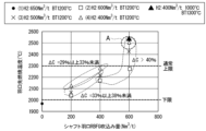
- the horizontal axis of Fig. 6 (shaft tuyere RBFG injection amount) indicates the injection amount (Nm 3 /t) of RBFG injected from the shaft tuyere 12 into the shaft section 10b of the blast furnace 10, and the vertical axis indicates the tuyere tip combustion temperature (°C).
- ⁇ C indicates Input ⁇ C.
- Fig. 6 a group of points where Input ⁇ C is 29% or more and less than 33%, a group where Input ⁇ C is 33% or more and less than 38%, and a group where Input ⁇ C is more than 40% are surrounded by dashed lines.
- the horizontal axis of Fig. 7 indicates the tuyere tip combustion temperature (°C), and the vertical axis indicates the furnace top exhaust gas temperature (°C).
- Figs. 6 and 7 also show, as a reference example, an example in which the blast temperature was 1300°C (BT 1300°C) and the hydrogen gas injection temperature was 1000°C in level 2-4.
- the following findings can be obtained.
- the tuyere combustion temperature increases.
- the top exhaust gas temperature depends greatly on the flow rate of gas supplied into the blast furnace, and the more the gas flow rate per pig iron output increases, the higher the top exhaust gas temperature.
- the tuyere combustion temperature depends greatly on the oxygen enrichment rate, which is the combustion condition at the tuyere, and the higher the oxygen enrichment rate, the higher the tuyere combustion temperature.
- increasing the oxygen enrichment rate reducing the amount of hot air blown and reducing the gas flow rate supplied from the tuyere, so if the oxygen enrichment rate is increased to increase the tuyere combustion temperature, the gas flow rate supplied into the furnace decreases and the top exhaust gas temperature decreases. Therefore, assuming that gas is normally blown from the tuyere 11, it is difficult to control the top exhaust gas temperature and the tuyere combustion temperature independently (because trying to move one of them will move the other in the opposite direction).
- gas at a temperature lower than the tuyere combustion temperature is supplied into the furnace, as in the first embodiment, but since RBFG is blown from the shaft 10b, not from the tuyere where the coke is burning (usually the end of the tuyere 11), the tuyere combustion temperature does not decrease even if the amount of RBFG blown is controlled. Therefore, it is possible to adjust the tuyere combustion temperature to an appropriate value by separately adjusting the oxygen enrichment rate at the tuyere while adjusting the furnace top exhaust gas temperature by increasing the amount of RBFG blown. This is one of the advantages of the second embodiment (the advantage is that gas is blown into a place other than the usual tuyere 11).
- the tuyere combustion temperature in level 2-4 is higher than those in levels 2-1 to 2-3.
- the tuyere combustion temperature in level 2-4 is sufficiently higher than the lower limit (2000°C).
- the furnace top exhaust gas temperature in level 2-4 is also sufficiently higher than the lower limit (105°C).
- the degree of freedom in operation is high (the range in which the operational parameters can be designed is wide). Note that if the Input ⁇ C of level 2-4 exceeds 40%, the tuyere tip combustion temperature will exceed the upper limit (2300°C) (point indicated by dashed circle A in Figure 6), but operation can be continued by taking the measures described above.
- the operation method of the blast furnace 10 according to the third embodiment is generally as follows. That is, iron-based raw materials and coke are alternately and layeredly charged into the blast furnace 10 from the top of the blast furnace 10, while heated hydrogen-based reducing gas is supplied from the hydrogen-based reducing gas supply system 2 to the normal tuyeres 11. Then, hot air, pulverized coal, enriched oxygen gas, and heated hydrogen-based reducing gas are blown into the blast furnace 10 from the normal tuyeres 11. Meanwhile, RBFG is blown into the blast furnace 10 from the normal tuyeres 11 and the shaft tuyeres 12.
- the hot air reacts with the pulverized coal blown in together with the hot air and the coke in the blast furnace 10 to generate high-temperature reducing gas (mainly CO gas in this case). That is, the hot air gasifies the coke and pulverized coal.
- the reducing gas rises inside the blast furnace 10 and reduces the iron-based raw materials while heating them.
- the hydrogen-based reducing gas and RBFG rise inside the blast furnace 10, heating and reducing the iron-based raw materials.
- the iron-based raw materials melt and drip inside the blast furnace 10 while being further reduced by coke.
- the iron-based raw materials are ultimately stored in the hearth as molten pig iron (pig iron) containing just under 5% by mass of carbon. The molten pig iron in the hearth is removed from the tap hole and used in the next steelmaking process.
- the CO2 separation and capture device 20 recovers the top flue gas and separates it into reducing gas (CO gas and hydrogen gas) and nitrogen gas (i.e., RBFG) and CO2 gas and H2O gas.
- the CO2 gas and H2O gas are discharged outside the system.
- RBFG is temporarily stored in the buffer tank 30.
- a desired amount of RBFG is introduced from the buffer tank 30 into the compressor 40.
- the remaining RBFG is discharged outside the system and used, for example, as a heat source in a steelworks.
- the RBFG is then pressurized by the compressor 40.
- the compressor 40 pressurizes the RBFG to, for example, the internal pressure of the blast furnace 10 (approximately 4.5 atmospheres).
- the pressurized RBFG is introduced into the heater 50.
- the RBFG is then heated by the heater 50.
- the heating temperature is set arbitrarily depending on the operating conditions of the blast furnace 10.
- the RBFG heated by the heater 50 is blown into the blast furnace 10 from the normal tuyere 11 and the shaft tuyere 12.
- the flowmeter 61 measures the flow rate of the RBFG blown into the blast furnace 10 from the normal tuyere 11.
- the flowmeter 62 measures the flow rate of the RBFG blown into the shaft 10b of the blast furnace 10 from the shaft tuyere 12.
- a specific example of the operating method is as described in the first embodiment.
- the tuyere combustion temperature is preferably maintained at about 2000 to 2300°C
- the furnace top exhaust gas temperature is preferably maintained at about 105°C or higher
- the molten iron temperature is preferably maintained at about 1520°C or higher.
- the upper limit value of the tuyere combustion temperature is an upper limit value assuming normal operation (operation without injection of hydrogen-based reducing gas or RBFG).
- the tuyere combustion temperature exceeds the upper limit value, it is preferable to take measures such as strengthening the cooling capacity of the tuyere equipment and using materials with higher heat resistance to prevent wear and tear on the tuyere equipment.
- the specifications of the blast furnace operation are determined so that the tuyere combustion temperature, furnace top exhaust gas temperature, and molten iron temperature are maintained within a specified range. As long as the tuyere combustion temperature, furnace top exhaust gas temperature, and molten iron temperature are maintained within the specified ranges, the blast furnace operation specifications can be freely designed. Also, although the tuyere combustion temperature may exceed the upper limit as a result of the design, it is preferable to take the above-mentioned measures separately.
- the blowing temperature of the hydrogen-based reducing gas (the temperature of the hydrogen-based reducing gas normally blown from the tuyere 11) is preferably about 800 to 1000°C, and the blowing amount of hydrogen gas in the hydrogen-based reducing gas is preferably about 300 to 600 Nm 3 /t. Both are in a range lower than that of Patent Document 1.
- the normal tuyere blowing temperature of the RBFG (the temperature of the RBFG normally blown from the tuyere 11, i.e., the heating temperature by the heater 50) is preferably about 800 to 1000°C, and the normal tuyere blowing amount of the RBFG is preferably about 100 to 300 Nm 3 /t.
- the shaft part tuyere blowing temperature of the RBFG (the temperature of the RBFG blown from the shaft part tuyere 12, i.e., the heating temperature by the heater 50) is preferably the same as the normal tuyere blowing temperature, and the shaft part tuyere blowing amount of the RBFG is preferably about 200 to 600 Nm 3 /t.
- the RBFG injection rate is preferably 600 Nm 3 /t or more in total of the normal tuyere injection rate and the shaft tuyere injection rate. This is because, as described later, in this case, the Input ⁇ C exceeds 40%.
- Other adjustable parameters include the hot air injection rate and the amount of oxygen contained in the hot air (oxygen injection rate).
- the molten pig iron temperature can also be adjusted by the amount of pulverized coal injected into the blast furnace 10 or the coke ratio (amount of coke used per ton of molten pig iron). For example, the molten pig iron temperature is first adjusted by the amount of pulverized coal injection, and if the molten pig iron temperature exceeds a predetermined range even when the amount of pulverized coal injection becomes zero, the coke ratio can be adjusted.
- the molten pig iron temperature is a value that reflects the total heat (furnace heat) in the blast furnace 10.
- the tuyere combustion temperature, the top exhaust gas temperature, and the hot metal temperature are monitored periodically (preferably all the time), and if any of the tuyere combustion temperature, the top exhaust gas temperature, and the hot metal temperature falls outside the above-mentioned range, the operating conditions (for example, as described above, at least one of the hydrogen-based reducing gas blowing temperature, the amount of hydrogen gas blown in the hydrogen-based reducing gas, the RBFG blowing temperature, the RBFG blowing amount, the hot blast blowing amount, and the amount of oxygen contained in the hot blast (the amount of enriched oxygen gas blown)) can be adjusted.
- the operating conditions for example, as described above, at least one of the hydrogen-based reducing gas blowing temperature, the amount of hydrogen gas blown in the hydrogen-based reducing gas, the RBFG blowing temperature, the RBFG blowing amount, the hot blast blowing amount, and the amount of oxygen contained in the hot blast (the amount of enriched oxygen gas blown)
- the tuyere combustion temperature, the top exhaust gas temperature, and the hot metal temperature are prone to fluctuate when blowing hydrogen-based reducing gas or RBFG, it is preferable to monitor the tuyere combustion temperature, the top exhaust gas temperature, and the hot metal temperature when blowing these gases.
- the simulation model is the same as that of the first embodiment.
- the prerequisites for the simulation are as follows. ⁇ Hydrogen gas is used as the hydrogen-based reducing gas.
- the CO2 separation and capture device 20 separates and removes 100% of the CO2 gas and H2O gas contained in the top flue gas.
- the hydrogen gas blowing temperature and the RBFG blowing temperature are set to 800°C.
- the hot air blowing temperature (air supply temperature) is 1200°C.
- the amount of molten iron produced and the temperature of the molten iron will be 12,350 t/d and 1,535°C.
- the top exhaust gas temperature is 132°C, and the tuyere combustion temperature is 2196°C.
- Furnace heat adjustment (adjustment of molten iron temperature) is performed by adjusting the amount of pulverized coal injected. If the molten iron temperature exceeds 1535°C even when the amount of pulverized coal injected becomes zero, the coke rate is adjusted. The amount of hot air and the amount of oxygen blown were adjusted so as to satisfy the above prerequisites.
- the hydrogen gas injection rate was 400 Nm3 /t
- the RBFG shaft tuyere injection rate was 400 Nm3 /t
- the normal tuyere injection rate was 200 Nm3 /t.
- the Input ⁇ C was 42.2%.
- the Input ⁇ C can be increased.
- Example 1 corresponds to the first embodiment
- Example 2 corresponds to the second embodiment
- Example 3 corresponds to the third embodiment.
- the CO2 separation and capture device 20 separates and removes 100% of the CO2 gas and H2O gas contained in the top flue gas.
- the amount of molten iron produced and the temperature of the molten iron will be 12,350 t/d and 1,535°C.
- the furnace top exhaust gas temperature is set near the lower limit (105°C) to maximize the carbon reduction effect.
- Furnace heat adjustment (adjustment of molten iron temperature) is performed by adjusting the amount of pulverized coal injected. If the molten iron temperature exceeds 1535°C even when the amount of pulverized coal injected becomes zero, the coke rate is adjusted.
- the amount of hot air and the amount of oxygen blown were adjusted so as to satisfy the above prerequisites. Hydrogen gas was blown (blowing temperature 1000°C, blowing amount 325 Nm 3 /t), hot air blowing temperature 1300°C, RBFG blowing temperature 1000°C, blowing amount 600 Nm 3 /t
- Example 2> (2-1. Main specifications) Hydrogen gas was used as the hydrogen-based reducing gas.
- the CO2 separation and capture device 20 separates and removes 100% of the CO2 gas and H2O gas contained in the top flue gas.
- the hydrogen gas blowing temperature and the RBFG blowing temperature are 800°C.
- the hot air blowing temperature (air supply temperature) is 1200°C.
- the amount of molten iron produced and the temperature of the molten iron will be 12,350 t/d and 1,535°C.
- the top exhaust gas temperature is 135°C.
- Furnace heat adjustment (adjustment of molten iron temperature) is performed by adjusting the amount of pulverized coal injected.
- Example 3> (3-1. Main specifications) ⁇ Hydrogen gas is used as the hydrogen-based reducing gas.
- the CO2 separation and capture device 20 separates and removes 100% of the CO2 gas and H2O gas contained in the top flue gas.
- the hydrogen gas blowing temperature and the RBFG blowing temperature are set to 800°C.
- the hot air blowing temperature (air supply temperature) is 1200°C.
- the amount of molten iron produced and the temperature of the molten iron will be 12,350 t/d and 1,535°C.
- the top exhaust gas temperature is 132°C, and the tuyere combustion temperature is 2196°C.
- - Furnace heat adjustment (adjustment of molten iron temperature) is performed by adjusting the amount of pulverized coal injected. If the molten iron temperature exceeds 1535°C even when the amount of pulverized coal injected becomes zero, the coke rate is adjusted. The amount of hot air and the amount of oxygen blown were adjusted so as to satisfy the above prerequisites.
- the hydrogen gas injection rate was 400 Nm 3 /t
- the RBFG shaft tuyere injection rate was 400 Nm 3 /t
- the normal tuyere injection rate was 200 Nm 3 /t.
- the Input ⁇ C can be increased.
- Blast furnace system 2 Hydrogen-based reducing gas supply system 10
- Blast furnace 10a Blast furnace body 10b Shaft section 11 Normal tuyere 12 Shaft section tuyere 20 CO2 separation and capture device 30
- Buffer tank 40 Compressor 50, 71 Heater 61, 62, 72 Flow meter 70 Hydrogen-based reducing gas tank
Landscapes
- Engineering & Computer Science (AREA)
- Chemical & Material Sciences (AREA)
- Manufacturing & Machinery (AREA)
- Materials Engineering (AREA)
- Metallurgy (AREA)
- Organic Chemistry (AREA)
- Manufacture Of Iron (AREA)
Priority Applications (4)
| Application Number | Priority Date | Filing Date | Title |
|---|---|---|---|
| KR1020257041961A KR20260011752A (ko) | 2023-06-21 | 2024-06-19 | 고로의 조업 방법 |
| EP24825948.3A EP4733420A1 (en) | 2023-06-21 | 2024-06-19 | Blast furnace operation method |
| CN202480040872.2A CN121368639A (zh) | 2023-06-21 | 2024-06-19 | 高炉的操作方法 |
| JP2025528095A JPWO2024262547A1 (https=) | 2023-06-21 | 2024-06-19 |
Applications Claiming Priority (2)
| Application Number | Priority Date | Filing Date | Title |
|---|---|---|---|
| JP2023101584 | 2023-06-21 | ||
| JP2023-101584 | 2023-06-21 |
Publications (1)
| Publication Number | Publication Date |
|---|---|
| WO2024262547A1 true WO2024262547A1 (ja) | 2024-12-26 |
Family
ID=93935464
Family Applications (1)
| Application Number | Title | Priority Date | Filing Date |
|---|---|---|---|
| PCT/JP2024/022266 Ceased WO2024262547A1 (ja) | 2023-06-21 | 2024-06-19 | 高炉の操業方法 |
Country Status (6)
| Country | Link |
|---|---|
| EP (1) | EP4733420A1 (https=) |
| JP (1) | JPWO2024262547A1 (https=) |
| KR (1) | KR20260011752A (https=) |
| CN (1) | CN121368639A (https=) |
| TW (1) | TWI906913B (https=) |
| WO (1) | WO2024262547A1 (https=) |
Citations (6)
| Publication number | Priority date | Publication date | Assignee | Title |
|---|---|---|---|---|
| JPS4979910A (https=) * | 1972-11-25 | 1974-08-01 | ||
| JP2009221547A (ja) * | 2008-03-17 | 2009-10-01 | Jfe Steel Corp | 高炉操業方法 |
| JP2020045508A (ja) * | 2018-09-14 | 2020-03-26 | 日本製鉄株式会社 | 高炉の操業方法 |
| JP2020132928A (ja) * | 2019-02-18 | 2020-08-31 | 日本製鉄株式会社 | 還元ガスの吹込み量決定方法及び高炉の操業方法 |
| WO2021107091A1 (ja) | 2019-11-29 | 2021-06-03 | 日本製鉄株式会社 | 高炉の操業方法 |
| JP2023101584A (ja) | 2019-04-03 | 2023-07-21 | レアード テクノロジーズ インコーポレイテッド | 低誘電率、低損失レドーム |
Family Cites Families (4)
| Publication number | Priority date | Publication date | Assignee | Title |
|---|---|---|---|---|
| JPS6448638A (en) * | 1987-08-17 | 1989-02-23 | Ryobi Ltd | Production of collapsible core |
| JP6258039B2 (ja) * | 2014-01-07 | 2018-01-10 | 新日鐵住金株式会社 | 高炉の操業方法 |
| EP4144868B1 (en) * | 2020-04-27 | 2024-07-24 | JFE Steel Corporation | Steelmaking line and method of producing reduced iron |
| JP2023035266A (ja) * | 2021-08-31 | 2023-03-13 | 株式会社クリーンプラネット | 高炉用水素加熱装置、高炉用水素加熱方法および高炉操業方法 |
-
2024
- 2024-06-18 TW TW113122443A patent/TWI906913B/zh active
- 2024-06-19 JP JP2025528095A patent/JPWO2024262547A1/ja active Pending
- 2024-06-19 KR KR1020257041961A patent/KR20260011752A/ko active Pending
- 2024-06-19 CN CN202480040872.2A patent/CN121368639A/zh active Pending
- 2024-06-19 WO PCT/JP2024/022266 patent/WO2024262547A1/ja not_active Ceased
- 2024-06-19 EP EP24825948.3A patent/EP4733420A1/en active Pending
Patent Citations (6)
| Publication number | Priority date | Publication date | Assignee | Title |
|---|---|---|---|---|
| JPS4979910A (https=) * | 1972-11-25 | 1974-08-01 | ||
| JP2009221547A (ja) * | 2008-03-17 | 2009-10-01 | Jfe Steel Corp | 高炉操業方法 |
| JP2020045508A (ja) * | 2018-09-14 | 2020-03-26 | 日本製鉄株式会社 | 高炉の操業方法 |
| JP2020132928A (ja) * | 2019-02-18 | 2020-08-31 | 日本製鉄株式会社 | 還元ガスの吹込み量決定方法及び高炉の操業方法 |
| JP2023101584A (ja) | 2019-04-03 | 2023-07-21 | レアード テクノロジーズ インコーポレイテッド | 低誘電率、低損失レドーム |
| WO2021107091A1 (ja) | 2019-11-29 | 2021-06-03 | 日本製鉄株式会社 | 高炉の操業方法 |
Non-Patent Citations (1)
| Title |
|---|
| KOUJI TAKATANITAKANOBU INADAYUTAKA UJISAWA: "Three-dimensional Dynamic Simulator for Blast Furnace", ISI) INTERNATIONAL, vol. 39, no. 1, 1999, pages 15 - 22 |
Also Published As
| Publication number | Publication date |
|---|---|
| CN121368639A (zh) | 2026-01-20 |
| TW202500764A (zh) | 2025-01-01 |
| TWI906913B (zh) | 2025-12-01 |
| EP4733420A1 (en) | 2026-04-29 |
| JPWO2024262547A1 (https=) | 2024-12-26 |
| KR20260011752A (ko) | 2026-01-23 |
Similar Documents
| Publication | Publication Date | Title |
|---|---|---|
| JP7297091B2 (ja) | 高炉の操業方法 | |
| CN113423845B (zh) | 高炉操作方法 | |
| JP6354962B2 (ja) | 酸素高炉の操業方法 | |
| CN104412056A (zh) | 利用炉顶煤气再循环的高炉 | |
| JP7055082B2 (ja) | 高炉の操業方法 | |
| JP4743332B2 (ja) | 高炉操業方法 | |
| CN119731344A (zh) | 用于操作冶炼炉设施的方法 | |
| CN119731343A (zh) | 用于操作冶炼炉设施的方法 | |
| CA3154824A1 (en) | Method of operating blast furnace and blast furnace ancillary facility | |
| JP7662417B2 (ja) | 高炉の操業方法 | |
| JP2023114182A (ja) | 高炉の操業方法 | |
| WO2024262547A1 (ja) | 高炉の操業方法 | |
| JP7709109B1 (ja) | 高炉の操業方法 | |
| JP7849593B2 (ja) | 高炉の操業方法 | |
| JP7817658B2 (ja) | 高炉の操業方法 | |
| JP7832483B2 (ja) | 高炉の操業方法 | |
| JP7791433B2 (ja) | 高炉の操業方法 | |
| EP4306660A1 (en) | Oxygen blast furnace and oxygen blast furnace operation method | |
| JP2025133638A (ja) | 高炉の操業方法 | |
| JP7832580B2 (ja) | 高炉の操業方法 | |
| JP2025148977A (ja) | 高炉の操業方法 | |
| KR101225116B1 (ko) | 제철 부생가스 제어장치 및 방법 | |
| KR102177047B1 (ko) | 용선 제조장치 및 용선 제조방법 | |
| JP2025100456A (ja) | 高炉の操業方法 | |
| JP2025130949A (ja) | 高炉の操業方法 |
Legal Events
| Date | Code | Title | Description |
|---|---|---|---|
| 121 | Ep: the epo has been informed by wipo that ep was designated in this application |
Ref document number: 24825948 Country of ref document: EP Kind code of ref document: A1 |
|
| DPE1 | Request for preliminary examination filed after expiration of 19th month from priority date (pct application filed from 20040101) | ||
| ENP | Entry into the national phase |
Ref document number: 2025528095 Country of ref document: JP Kind code of ref document: A |
|
| ENP | Entry into the national phase |
Ref document number: 1020257041961 Country of ref document: KR Free format text: ST27 STATUS EVENT CODE: A-0-1-A10-A15-NAP-PA0105 (AS PROVIDED BY THE NATIONAL OFFICE) |
|
| WWE | Wipo information: entry into national phase |
Ref document number: 1020257041961 Country of ref document: KR |
|
| REG | Reference to national code |
Ref country code: BR Ref legal event code: B01A Ref document number: 112025027239 Country of ref document: BR |
|
| WWE | Wipo information: entry into national phase |
Ref document number: 202617001738 Country of ref document: IN |
|
| WWE | Wipo information: entry into national phase |
Ref document number: 2024825948 Country of ref document: EP |
|
| NENP | Non-entry into the national phase |
Ref country code: DE |
|
| WWP | Wipo information: published in national office |
Ref document number: 1020257041961 Country of ref document: KR Ref document number: 202617001738 Country of ref document: IN |
|
| ENP | Entry into the national phase |
Ref document number: 2024825948 Country of ref document: EP Effective date: 20260121 |
|
| ENP | Entry into the national phase |
Ref document number: 2024825948 Country of ref document: EP Effective date: 20260121 |
|
| ENP | Entry into the national phase |
Ref document number: 2024825948 Country of ref document: EP Effective date: 20260121 |