WO2024262381A1 - 水素極-固体電解質層複合体、プロトン伝導型セル構造体、燃料電池、水蒸気電解セル、及び水素極-固体電解質層複合体の製造方法 - Google Patents
水素極-固体電解質層複合体、プロトン伝導型セル構造体、燃料電池、水蒸気電解セル、及び水素極-固体電解質層複合体の製造方法 Download PDFInfo
- Publication number
- WO2024262381A1 WO2024262381A1 PCT/JP2024/021128 JP2024021128W WO2024262381A1 WO 2024262381 A1 WO2024262381 A1 WO 2024262381A1 JP 2024021128 W JP2024021128 W JP 2024021128W WO 2024262381 A1 WO2024262381 A1 WO 2024262381A1
- Authority
- WO
- WIPO (PCT)
- Prior art keywords
- hydrogen electrode
- solid electrolyte
- electrolyte layer
- layer composite
- pores
- Prior art date
- Legal status (The legal status is an assumption and is not a legal conclusion. Google has not performed a legal analysis and makes no representation as to the accuracy of the status listed.)
- Ceased
Links
Images


Classifications
-
- C—CHEMISTRY; METALLURGY
- C25—ELECTROLYTIC OR ELECTROPHORETIC PROCESSES; APPARATUS THEREFOR
- C25B—ELECTROLYTIC OR ELECTROPHORETIC PROCESSES FOR THE PRODUCTION OF COMPOUNDS OR NON-METALS; APPARATUS THEREFOR
- C25B1/00—Electrolytic production of inorganic compounds or non-metals
- C25B1/01—Products
- C25B1/02—Hydrogen or oxygen
- C25B1/04—Hydrogen or oxygen by electrolysis of water
- C25B1/042—Hydrogen or oxygen by electrolysis of water by electrolysis of steam
-
- C—CHEMISTRY; METALLURGY
- C25—ELECTROLYTIC OR ELECTROPHORETIC PROCESSES; APPARATUS THEREFOR
- C25B—ELECTROLYTIC OR ELECTROPHORETIC PROCESSES FOR THE PRODUCTION OF COMPOUNDS OR NON-METALS; APPARATUS THEREFOR
- C25B11/00—Electrodes; Manufacture thereof not otherwise provided for
- C25B11/02—Electrodes; Manufacture thereof not otherwise provided for characterised by shape or form
- C25B11/03—Electrodes; Manufacture thereof not otherwise provided for characterised by shape or form perforated or foraminous
- C25B11/031—Porous electrodes
-
- C—CHEMISTRY; METALLURGY
- C25—ELECTROLYTIC OR ELECTROPHORETIC PROCESSES; APPARATUS THEREFOR
- C25B—ELECTROLYTIC OR ELECTROPHORETIC PROCESSES FOR THE PRODUCTION OF COMPOUNDS OR NON-METALS; APPARATUS THEREFOR
- C25B11/00—Electrodes; Manufacture thereof not otherwise provided for
- C25B11/04—Electrodes; Manufacture thereof not otherwise provided for characterised by the material
- C25B11/051—Electrodes formed of electrocatalysts on a substrate or carrier
- C25B11/054—Electrodes comprising electrocatalysts supported on a carrier
-
- C—CHEMISTRY; METALLURGY
- C25—ELECTROLYTIC OR ELECTROPHORETIC PROCESSES; APPARATUS THEREFOR
- C25B—ELECTROLYTIC OR ELECTROPHORETIC PROCESSES FOR THE PRODUCTION OF COMPOUNDS OR NON-METALS; APPARATUS THEREFOR
- C25B11/00—Electrodes; Manufacture thereof not otherwise provided for
- C25B11/04—Electrodes; Manufacture thereof not otherwise provided for characterised by the material
- C25B11/051—Electrodes formed of electrocatalysts on a substrate or carrier
- C25B11/055—Electrodes formed of electrocatalysts on a substrate or carrier characterised by the substrate or carrier material
- C25B11/057—Electrodes formed of electrocatalysts on a substrate or carrier characterised by the substrate or carrier material consisting of a single element or compound
- C25B11/067—Inorganic compound e.g. ITO, silica or titania
-
- C—CHEMISTRY; METALLURGY
- C25—ELECTROLYTIC OR ELECTROPHORETIC PROCESSES; APPARATUS THEREFOR
- C25B—ELECTROLYTIC OR ELECTROPHORETIC PROCESSES FOR THE PRODUCTION OF COMPOUNDS OR NON-METALS; APPARATUS THEREFOR
- C25B11/00—Electrodes; Manufacture thereof not otherwise provided for
- C25B11/04—Electrodes; Manufacture thereof not otherwise provided for characterised by the material
- C25B11/051—Electrodes formed of electrocatalysts on a substrate or carrier
- C25B11/073—Electrodes formed of electrocatalysts on a substrate or carrier characterised by the electrocatalyst material
- C25B11/075—Electrodes formed of electrocatalysts on a substrate or carrier characterised by the electrocatalyst material consisting of a single catalytic element or catalytic compound
- C25B11/089—Alloys
-
- C—CHEMISTRY; METALLURGY
- C25—ELECTROLYTIC OR ELECTROPHORETIC PROCESSES; APPARATUS THEREFOR
- C25B—ELECTROLYTIC OR ELECTROPHORETIC PROCESSES FOR THE PRODUCTION OF COMPOUNDS OR NON-METALS; APPARATUS THEREFOR
- C25B9/00—Cells or assemblies of cells; Constructional parts of cells; Assemblies of constructional parts, e.g. electrode-diaphragm assemblies; Process-related cell features
-
- C—CHEMISTRY; METALLURGY
- C25—ELECTROLYTIC OR ELECTROPHORETIC PROCESSES; APPARATUS THEREFOR
- C25B—ELECTROLYTIC OR ELECTROPHORETIC PROCESSES FOR THE PRODUCTION OF COMPOUNDS OR NON-METALS; APPARATUS THEREFOR
- C25B9/00—Cells or assemblies of cells; Constructional parts of cells; Assemblies of constructional parts, e.g. electrode-diaphragm assemblies; Process-related cell features
- C25B9/17—Cells comprising dimensionally-stable non-movable electrodes; Assemblies of constructional parts thereof
- C25B9/19—Cells comprising dimensionally-stable non-movable electrodes; Assemblies of constructional parts thereof with diaphragms
- C25B9/23—Cells comprising dimensionally-stable non-movable electrodes; Assemblies of constructional parts thereof with diaphragms comprising ion-exchange membranes in or on which electrode material is embedded
-
- H—ELECTRICITY
- H01—ELECTRIC ELEMENTS
- H01M—PROCESSES OR MEANS, e.g. BATTERIES, FOR THE DIRECT CONVERSION OF CHEMICAL ENERGY INTO ELECTRICAL ENERGY
- H01M4/00—Electrodes
- H01M4/86—Inert electrodes with catalytic activity, e.g. for fuel cells
-
- H—ELECTRICITY
- H01—ELECTRIC ELEMENTS
- H01M—PROCESSES OR MEANS, e.g. BATTERIES, FOR THE DIRECT CONVERSION OF CHEMICAL ENERGY INTO ELECTRICAL ENERGY
- H01M4/00—Electrodes
- H01M4/86—Inert electrodes with catalytic activity, e.g. for fuel cells
- H01M4/90—Selection of catalytic material
-
- H—ELECTRICITY
- H01—ELECTRIC ELEMENTS
- H01M—PROCESSES OR MEANS, e.g. BATTERIES, FOR THE DIRECT CONVERSION OF CHEMICAL ENERGY INTO ELECTRICAL ENERGY
- H01M8/00—Fuel cells; Manufacture thereof
- H01M8/10—Fuel cells with solid electrolytes
- H01M8/12—Fuel cells with solid electrolytes operating at high temperature, e.g. with stabilised ZrO2 electrolyte
-
- H—ELECTRICITY
- H01—ELECTRIC ELEMENTS
- H01M—PROCESSES OR MEANS, e.g. BATTERIES, FOR THE DIRECT CONVERSION OF CHEMICAL ENERGY INTO ELECTRICAL ENERGY
- H01M8/00—Fuel cells; Manufacture thereof
- H01M8/10—Fuel cells with solid electrolytes
- H01M8/12—Fuel cells with solid electrolytes operating at high temperature, e.g. with stabilised ZrO2 electrolyte
- H01M8/124—Fuel cells with solid electrolytes operating at high temperature, e.g. with stabilised ZrO2 electrolyte characterised by the process of manufacturing or by the material of the electrolyte
- H01M8/1246—Fuel cells with solid electrolytes operating at high temperature, e.g. with stabilised ZrO2 electrolyte characterised by the process of manufacturing or by the material of the electrolyte the electrolyte consisting of oxides
-
- Y—GENERAL TAGGING OF NEW TECHNOLOGICAL DEVELOPMENTS; GENERAL TAGGING OF CROSS-SECTIONAL TECHNOLOGIES SPANNING OVER SEVERAL SECTIONS OF THE IPC; TECHNICAL SUBJECTS COVERED BY FORMER USPC CROSS-REFERENCE ART COLLECTIONS [XRACs] AND DIGESTS
- Y02—TECHNOLOGIES OR APPLICATIONS FOR MITIGATION OR ADAPTATION AGAINST CLIMATE CHANGE
- Y02E—REDUCTION OF GREENHOUSE GAS [GHG] EMISSIONS, RELATED TO ENERGY GENERATION, TRANSMISSION OR DISTRIBUTION
- Y02E60/00—Enabling technologies; Technologies with a potential or indirect contribution to GHG emissions mitigation
- Y02E60/30—Hydrogen technology
- Y02E60/50—Fuel cells
Definitions
- Patent Document 1 discloses a method for manufacturing a hydrogen electrode-solid electrolyte layer composite that can form a proton-conducting cell structure with excellent current efficiency.
- the manufacturing method described in Patent Document 1 suppresses the diffusion of nickel into the solid electrolyte layer. Therefore, steam electrolysis cells and fuel cells that use the hydrogen electrode-solid electrolyte layer composite obtained by the manufacturing method described in Patent Document 1 exhibit high current efficiency.
- Another aspect of the present disclosure relates to a proton-conducting cell structure comprising the hydrogen electrode-solid electrolyte layer composite of the present disclosure and a porous oxygen electrode in contact with the solid electrolyte layer, the solid electrolyte layer being interposed between the oxygen electrode and the hydrogen electrode, and the oxygen electrode being a compound having a perovskite structure.
- Another aspect of the present disclosure relates to a fuel cell comprising the proton conducting cell structure of the present disclosure.
- Another aspect of the present disclosure relates to a steam electrolysis cell having the proton conductive cell structure of the present disclosure.
- the method for producing a hydrogen electrode-solid electrolyte layer composite includes a hydrogen electrode having pores and a solid electrolyte layer in contact with the hydrogen electrode, and includes a first step of preparing a first paste sheet as a precursor of the solid electrolyte layer, and a second paste sheet and a third paste sheet as precursors of the hydrogen electrode, a second step of stacking the first paste sheet, the second paste sheet, and the third paste sheet in the order of the first paste sheet, the second paste sheet, and the third paste sheet to obtain a paste sheet laminate, a third step of heat-treating the paste sheet laminate to obtain a sintered body, a fourth step of impregnating the sintered body with a nickel compound solution to obtain a nickel-impregnated sintered body, and a fifth step of heat-treating the nickel-impregnated sintered body to obtain a hydrogen electrode-solid electrolyte layer composite.
- FIG. 1 is a scanning electron microscope photograph showing a cross section of the hydrogen electrode-solid electrolyte layer composite according to this embodiment.
- FIG. 2 is an enlarged photograph of the vicinity of the contact surface of FIG.
- FIG. 3 is an enlarged photograph of the vicinity of the surface of the hydrogen electrode in FIG.
- FIG. 4 is an explanatory diagram of the porosity, coating rate, and impregnation rate.
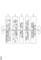
- FIG. 5 is a flow diagram of a method for producing a hydrogen electrode-solid electrolyte layer composite.
- FIG. 6 is a schematic diagram of a proton conductive cell structure including a hydrogen electrode-solid electrolyte layer composite according to this embodiment.
- FIG. 7 is a schematic diagram of a fuel cell including a proton conductive cell structure according to this embodiment.
- the present disclosure aims to provide a hydrogen electrode-solid electrolyte layer composite for forming a proton conductive cell structure having excellent current efficiency and power density.
- the present disclosure also aims to provide a proton conductive cell structure including the above-mentioned hydrogen electrode-solid electrolyte layer composite.
- the present disclosure aims to provide a fuel cell and a steam electrolysis cell including the above-mentioned proton conductive cell structure.
- the present disclosure aims to provide a method for manufacturing the above-mentioned hydrogen electrode-solid electrolyte layer composite.
- a hydrogen electrode-solid electrolyte layer composite is a hydrogen electrode-solid electrolyte layer composite including a hydrogen electrode having pores and a solid electrolyte layer in contact with the hydrogen electrode, the hydrogen electrode and the solid electrolyte layer each containing a metal oxide, the metal oxide having a perovskite structure and represented by the following formula (1):
- a x B 1-y M y O 3- ⁇ (1) (wherein element A is at least one selected from the group consisting of Ba, Ca and Sr, element B is at least one selected from the group consisting of Ce and Zr, element M is at least one selected from the group consisting of Y, Yb, Er, Ho, Tm, Gd, In and Sc, and ⁇ is the amount of oxygen deficiency, satisfying 0.95 ⁇ x ⁇ 1 and 0 ⁇ y ⁇ 0.5).
- the hydrogen electrode has a nickel component in the pores, and the pores have a first average diameter or a second average diameter.
- the first average diameter is the average value of the outer diameters of the 10 largest pores, selected from 100 pores whose outer periphery is 70% or more visible in a region from the contact surface between the hydrogen electrode and the solid electrolyte layer to a depth of 50 ⁇ m
- the second average diameter is the average value of the outer diameters of the 10 largest pores, selected from 20 pores whose outer periphery is 70% or more visible in a region from the surface of the hydrogen electrode opposite the contact surface to a depth of 200 ⁇ m, and the first average diameter is smaller than the second average diameter.
- the hydrogen electrode-solid electrolyte layer composite described in (1) above makes it possible to form a proton-conducting cell structure with excellent current efficiency and power density.
- the first average diameter may be 10 ⁇ m or more and 40 ⁇ m or less
- the second average diameter may be 30 ⁇ m or more and 200 ⁇ m or less.
- the hydrogen electrode includes a first area including the contact surface, a second area including the surface, and an interface between the first area and the second area, and the first area may have a porosity of 60% or more and 90% or less, and the second area may have a porosity of 40% or more and 90% or less.
- the hydrogen electrode includes a first area including the contact surface, a second area including the surface, and an interface between the first area and the second area, and the average film thickness from the contact surface to the interface may be 50 ⁇ m or more and 300 ⁇ m or less, and the average film thickness from the surface to the interface may be 200 ⁇ m or more and 1000 ⁇ m or less.
- the coating rate of the nickel component in the pores in the first area may be 20% or more and 75% or less.
- the impregnation rate of the nickel component in the pores in the first area may be 15% or more and less than 45%.
- element A may be Ba
- element B may be Zr
- element M may be Y or Yb.
- a proton-conducting cell structure comprises a hydrogen electrode-solid electrolyte layer composite according to any one of (1) to (8) above, and a porous oxygen electrode in contact with the solid electrolyte layer, the solid electrolyte layer being interposed between the oxygen electrode and the hydrogen electrode, and the oxygen electrode being a compound having a perovskite structure.
- the proton conductive cell structure (9) above has excellent current efficiency and power density.
- the oxygen electrode may be lanthanum strontium cobalt ferrite or lanthanum strontium cobaltite.
- the proton conductive cell structure (10) above has better current efficiency and power density.
- a steam electrolysis cell according to another embodiment of the present disclosure includes a proton-conducting cell structure as described in (9) or (10) above.
- the fuel cell (11) and the steam electrolysis cell (12) above are equipped with a proton-conducting cell structure that has excellent current efficiency and power density.
- a method for producing a hydrogen electrode-solid electrolyte layer composite is a method for producing a hydrogen electrode-solid electrolyte layer composite comprising a hydrogen electrode having pores and a solid electrolyte layer in contact with the hydrogen electrode, the method comprising the steps of: a first step of preparing a first paste sheet as a precursor of the solid electrolyte layer, and a second paste sheet and a third paste sheet as precursors of the hydrogen electrode; a second step of stacking the first paste sheet, the second paste sheet, and the third paste sheet in the order of the first paste sheet, the second paste sheet, and the third paste sheet to obtain a paste sheet laminate; a third step of heat-treating the paste sheet laminate to obtain a sintered body; a fourth step of impregnating the sintered body with a nickel compound solution to obtain a nickel-impregnated sintered body; and a fifth step of heat-treating the nickel-impregnated sintered body to obtain a hydrogen electrode-solid electrolyt
- the first paste sheet contains a metal oxide, and the metal oxide has a perovskite structure and is represented by the following formula (1): A x B 1-y M y O 3- ⁇ (1) (wherein, element A is at least one selected from the group consisting of Ba, Ca and Sr, element B is at least one selected from the group consisting of Ce and Zr, element M is at least one selected from the group consisting of Y, Yb, Er, Ho, Tm, Gd, In and Sc, and ⁇ is the amount of oxygen deficiency, satisfying 0.95 ⁇ x ⁇ 1, 0 ⁇ y ⁇ 0.5).
- the second paste sheet includes the metal oxide and a first pore-forming material having a first median diameter
- the third paste sheet includes the metal oxide and a second pore-forming material having a second median diameter. The first median diameter is smaller than the second median diameter.
- the manufacturing method (13) above can produce a hydrogen electrode-solid electrolyte layer composite that can form a proton-conducting cell structure with excellent current efficiency and power density.
- the third step may be a step of heat-treating the paste sheet laminate at 400°C or more and 1000°C or less, removing at least a portion of the first pore-forming material and the second pore-forming material, and then heat-treating the laminate at 1400°C or more and 1650°C or less to obtain a sintered body.
- the fifth step may be a step of heat treating the nickel-impregnated sintered body at 200°C or higher and 600°C or lower to fix the nickel component in the pores of the hydrogen electrode, thereby obtaining a hydrogen electrode-solid electrolyte layer composite.
- the ratio of the second median diameter to the first median diameter may be 2.5 or more and 10 or less.
- the first median diameter may be 15 ⁇ m or more and 50 ⁇ m or less
- the second median diameter may be 30 ⁇ m or more and 200 ⁇ m or less.
- FIG. 1 is a cross-sectional scanning electron microscope photograph (hereinafter sometimes simply referred to as a "cross-sectional SEM photograph") showing a hydrogen electrode-solid electrolyte layer composite according to this embodiment.
- the hydrogen electrode-solid electrolyte layer composite 1 shown in Fig. 1 comprises a hydrogen electrode 10 having pores 13, and a solid electrolyte layer 20.
- the hydrogen electrode 10 is porous.
- the solid electrolyte layer 20 is dense.
- the hydrogen electrode 10 and the solid electrolyte layer 20 are adjacent to each other and in contact with each other at a contact surface 41.
- the hydrogen electrode 10 has a first area 11 having a contact surface 41.
- the hydrogen electrode 10 includes a second area 12 having a hydrogen electrode surface 42 which is the surface of the hydrogen electrode.
- the first area and the second area are adjacent to each other and in contact with each other at a boundary surface 40.
- FIG. 2 is an enlarged photograph of the vicinity of the contact surface 41 surrounded by dotted line A in FIG. 1.
- FIG. 3 is an enlarged photograph of the vicinity of the hydrogen electrode surface 42 surrounded by dotted line B in FIG. 1.
- the hydrogen electrode 10 has nickel components 14 in the pores 13.
- nickel components 14 refer to those determined to be nickel by SEM-EDX.
- the hydrogen electrode-solid electrolyte layer composite 1 is configured so that the outer diameter of the pores 13 present in the first area 11 is smaller than the outer diameter of the pores 13 present in the second area 12. That is, in the hydrogen electrode-solid electrolyte layer composite 1, the first average diameter of the pores 13 present in the first area 11 is smaller than the second average diameter of the pores 13 present in the second area 12. This enables the hydrogen electrode-solid electrolyte layer composite 1 to form a proton conductive cell structure with excellent current efficiency and power density.
- the "outermost diameter” is the diameter of the circle when the cross-sectional shape of the pores 13 is a perfect circle, and is the maximum length of the distance between two points on the outer circumference when the cross-sectional shape of the pores 13 is not a perfect circle.
- a cross-sectional SEM photograph of the hydrogen electrode-solid electrolyte layer composite 1 containing 100 or more pores 13 with 70% or more of the periphery being visible in a region from the contact surface 41 to a depth of 50 ⁇ m is obtained.
- A-2 100 pores 13 are selected from the obtained cross-sectional SEM photograph.
- A-3) The outer diameters of the selected 100 pores 13 are measured.
- A-4) Of the measured outer diameters the largest 10 outer diameters are extracted.
- A-5) The average value of the extracted 10 outer diameters is obtained as a first average diameter.
- the ratio of the second average diameter to the first average diameter can be 2.0 or more and 10 or less, particularly 2.0 or more and 8 or less.
- the first average diameter can be 10 ⁇ m or more and 40 ⁇ m or less, particularly 10 ⁇ m or more and 35 ⁇ m or less.
- the second average diameter can be 30 ⁇ m or more and 200 ⁇ m or less, particularly 30 ⁇ m or more and 125 ⁇ m or less. This allows the hydrogen electrode-solid electrolyte layer composite 1 to form a proton conductive cell structure with better current efficiency and power density.
- the average thickness of the first area 11 from the contact surface 41 to the boundary surface 40 is the first average thickness 51.
- the first average thickness 51 can be 50 ⁇ m or more and 300 ⁇ m or less.
- the average thickness of the second area 12 from the hydrogen electrode surface 42 to the boundary surface 40 is the second average thickness 52.
- the second average thickness 52 can be 200 ⁇ m or more and 1000 ⁇ m or less.
- the average thickness 50 of the hydrogen electrode 10 can be 250 ⁇ m or more and 1300 ⁇ m or less.
- the average thickness 53 of the solid electrolyte layer 20 can be 20 ⁇ m or more and 40 ⁇ m or less.
- the average thickness is the average value of the thickness measured at three points within the same field of view.
- the hydrogen electrode 10 and the solid electrolyte layer 20 each contain a metal oxide.
- the metal oxide has a perovskite structure and is represented by the following formula (1).
- the A site contains an element A
- the B site contains an element B (not representing boron).
- a part of the B site is substituted with an element M in order to ensure high proton conductivity.
- Element A is at least one element selected from the group consisting of Ba (barium), Ca (calcium) and Sr (strontium).
- Element A can contain Ba. This provides excellent proton conductivity.
- the ratio of Ba in element A can be 50 atomic % or more, particularly 80 atomic % or more.
- Element A can be composed of Ba only.
- Element B is at least one element selected from the group consisting of Ce (cerium) and Zr (zirconium). Element B may contain Zr. This improves the durability of the hydrogen electrode 10 and the solid electrolyte layer 20.
- the ratio of Zr in element B may be 50 atomic % or more, particularly 80 atomic % or more. Element B may be composed of Zr only.
- the element M is at least one selected from the group consisting of Y (yttrium), Yb (ytterbium), Er (erbium), Ho (holmium), Tm (thulium), Gd (gadolinium), In (indium) and Sc (scandium).
- the element M is a dopant that creates oxygen vacancies, causing the metal oxide having a perovskite structure to exhibit proton conductivity.
- metal oxides having a perovskite structure include yttrium-doped barium zirconate [ BaxZr1 - yYyO3 - ⁇ ] (hereinafter sometimes simply referred to as "BZY”), ytterbium-doped barium zirconate [ BaxZr1 - yYbyO3 - ⁇ ] (hereinafter sometimes simply referred to as "BZYb”), yttrium-doped barium cerate [ BaxCe1- yYyO3 - ⁇ ], yttrium-doped barium zirconate /barium cerate mixed oxide [ BaxZr1 -y- zCezYyO3 - ⁇ ], etc.
- the hydrogen electrode 10 and the solid electrolyte layer 20 may include at least one selected from BZY and BZYb.
- FIG. 4 is an explanatory diagram of the porosity, coating rate, and impregnation rate.
- the upper part of FIG. 4 shows the energy dispersive X-ray analysis (hereinafter, simply referred to as "EDX") of the hydrogen electrode-solid electrolyte layer composite 1.
- EDX energy dispersive X-ray analysis
- 4 shows, from the top to the bottom, a schematic diagram showing the calculation formula for the porosity, a schematic diagram showing the calculation formula for the coating rate, and A schematic diagram visually showing the above and a schematic diagram visually showing the formula for calculating the impregnation rate are shown.
- a mapping image is obtained by mapping Ba and Ni in the hydrogen electrode-solid electrolyte layer composite 1 using EDX.
- an analysis image is obtained by analyzing the pores 13 and nickel components 14 in the mapping image.
- the analysis of the pores 13 and nickel components 14 in the mapping image was performed using a general program built using Python (registered trademark).
- the porosity, coating rate, and impregnation rate are determined based on the acquired analysis image.
- the porosity is a value indicating the proportion of the pores 13 in the target area of the hydrogen electrode 10.
- the porosity is calculated from the cross-sectional area of the pores 13 and the cross-sectional area of the target area obtained from the above-mentioned analysis image.
- the porosity is calculated by the following formula (2). When expressing the porosity as a percentage, the value obtained by the following formula (2) is multiplied by 100.
- Porosity Cross-sectional area of pores ⁇ Cross-sectional area of target area (2)
- the coating rate is a value indicating the proportion of the area covered with the nickel component 14 on the inner surface of the pore 13.
- the coating rate is calculated from the cross-sectional length of the nickel component 14 and the cross-sectional length of the pore 13 obtained from the above-mentioned analysis image.
- the cross-sectional length of the pore 13 is the outer periphery length of the cross section of the pore 13.
- the cross-sectional length of the nickel component 14 is the total periphery length surrounding the area of the nickel component 14 in the cross section of the pore 13.
- the calculation formula for the coating rate is expressed by the following formula (3). When expressing it as a percentage, the value obtained by the following formula (3) is multiplied by 100.
- Coating rate cross-sectional length of nickel component ⁇ 2 ⁇ cross-sectional length of pore (3)
- the impregnation rate is a value indicating the proportion of the nickel component 14 in the pores 13.
- the impregnation rate is calculated from the cross-sectional area of the nickel component 14 and the cross-sectional area of the pores obtained from the above-mentioned analysis image.
- the impregnation rate is calculated by the following formula (4). When expressing the impregnation rate as a percentage, the value obtained by the following formula (4) is multiplied by 100.
- Impregnation rate cross-sectional area of nickel component ⁇ cross-sectional area of pores (4)
- the porosity of the first area 11 can be 60% or more and 90% or less, particularly 60% or more and 80% or less.
- the porosity of the second area 12 can be 40% or more and 90% or less, particularly 40% or more and 80% or less. This allows the hydrogen electrode-solid electrolyte layer composite 1 to form a proton conductive cell structure with better current efficiency and power density.
- the application rate of the nickel component 14 in the hydrogen electrode 10 can be 10% or more and 90% or less, particularly 20% or more and 75% or less.
- the impregnation rate of the hydrogen electrode 10 can be 3% or more and 60% or less, particularly 15% or more and 40% or less.
- the application rate of the first area 11 is preferably 20% or more and 75% or less.
- the impregnation rate of the nickel component in the first area 11 is preferably 15% or more and less than 45%. This ensures that the nickel component 14 functions as a catalyst component in the hydrogen electrode 10. Furthermore, the electrical conductivity of the hydrogen electrode 10 is ensured. Therefore, the hydrogen electrode-solid electrolyte layer composite 1 can form a proton-conducting cell structure with better current efficiency and power density.
- Fig. 5 is a flow diagram of a method for producing the hydrogen electrode-solid electrolyte layer composite 1. As shown in Fig. 5, the method for producing the hydrogen electrode-solid electrolyte layer composite 1 includes five steps, from a first step S1 to a fifth step S5.
- the first step S1 is a step of preparing a first paste sheet which is a precursor of the solid electrolyte layer 20, and a second paste sheet and a third paste sheet which are precursors of the hydrogen electrode 10.
- the first paste sheet contains a metal oxide and does not contain a pore-forming material.
- the metal oxide has a perovskite structure and is represented by the above formula (1).
- the second paste sheet contains a metal oxide and a first pore-forming material.
- the metal oxide has a perovskite structure and is represented by the above formula (1).
- the third paste sheet contains a metal oxide and a second pore-forming material.
- the metal oxide has a perovskite structure and is represented by the above formula (1). It is preferable that the metal oxides contained in the first paste sheet, the second paste sheet, and the third paste sheet are the same.
- the second paste sheet is a precursor of the first area 11.
- the third paste sheet is a precursor of the second area 12.
- the first pore-forming material contained in the second paste sheet has a first median diameter.
- the second pore-forming material contained in the third paste sheet has a second median diameter.
- the first median diameter is smaller than the second median diameter. This makes it possible to manufacture a hydrogen electrode-solid electrolyte layer composite 1 having a first average diameter smaller than the second average diameter.
- the above-mentioned paste sheets may contain a binder as necessary.
- the binder include known materials used in the manufacture of ceramic materials, such as polymer binders and waxes, but are not limited thereto.
- the polymer binder include butyral resins, cellulose derivatives, vinyl acetate resins, and acrylic resins.
- the butyral resins include polyvinyl butyral.
- the cellulose derivatives include ethyl cellulose and cellulose ether.
- the concept of vinyl acetate resins includes saponified vinyl acetate resins such as propyl alcohol.
- the waxes include paraffin wax.
- Each of the above paste sheets may contain a dispersion medium as necessary.
- the dispersion medium include, but are not limited to, water and organic solvents.
- the organic solvent include hydrocarbons such as toluene; alcohols such as ethanol and isopropanol; and carbitols such as butyl carbitol acetate.
- the third step S3 is a step of heat-treating the paste sheet laminate obtained in the second step S2 to obtain a sintered body.
- the paste sheet laminate in which the green sheets are laminated is treated under a temperature of 60° C. to 80° C. and a pressure of 20 kgf/cm 2 to 40 kgf/cm 2. This causes the paste sheet laminate to be pressure-bonded.
- the paste sheet laminate is heat-treated at 400° C. to 1000° C. This removes at least a part of the binder, the first pore-forming material contained in the second paste sheet, and the second pore-forming material contained in the third paste sheet.
- the paste sheet laminate after the heat treatment is further heat-treated at 1400° C. to 1650° C. to obtain a sintered body.
- the heat treatment may be performed under conditions of 1500° C. to 1650° C. This produces a hydrogen electrode-solid electrolyte layer composite 1 capable of forming a proton-conducting cell structure having better current efficiency and power density.
- the heat treatment for removing the binder, the first pore-forming material, and the second pore-forming material may be omitted.
- the paste sheet laminate is heat-treated at 1400° C. or more and 1650° C. or less to obtain a sintered body.
- the fourth step S4 is a step of impregnating the sintered body obtained in the third step S3 with a nickel compound solution to obtain a nickel-impregnated sintered body.
- the nickel compound solution may be, for example, a solution containing nickel powder, a dispersing agent, and ⁇ -terpineol.
- the particle size of the nickel powder is, for example, 1 ⁇ m or less.
- the respective contents of the nickel powder, the dispersing agent, and ⁇ -terpineol are, for example, 82 mass %, 2 mass %, and 16 mass %, respectively.
- the nickel compound solution is impregnated into the pores of the sintered body by the fourth step S4.
- the impregnation process of the nickel compound solution may be appropriately selected depending on the type and state of the nickel compound solution, and is not particularly limited. For example, when the impregnation ability of the nickel compound solution is low, reduced pressure impregnation or pressurized impregnation is selected. When the impregnation ability of the nickel compound solution is high, an impregnation method such as dripping the nickel compound solution onto the sintered body or immersing the sintered body in the nickel compound solution is selected.
- a nickel compound solution, nano Ni slurry is dripped onto the surface of the sintered body that will become the hydrogen electrode 10 (hereinafter, simply referred to as "drop impregnation") to obtain a nickel-impregnated sintered body.
- the nickel compound solution is impregnated into the pores of the sintered body of the second paste sheet through the pores of the sintered body of the third paste sheet.
- the first median diameter of the first pore-forming material contained in the second paste sheet is smaller than the second median diameter of the second pore-forming material contained in the third paste sheet. Therefore, the pores of the sintered body of the third paste sheet are larger than the pores of the sintered body of the second paste sheet.
- the nickel compound solution easily passes through the sintered body of the third paste sheet, which has large pores. This promotes the impregnation of the nickel compound solution into the pores of the sintered body of the second paste sheet.
- a hydrogen electrode-solid electrolyte layer composite 1 capable of forming a proton conductive cell structure having sufficient current efficiency and power density is manufactured.
- the impregnation treatment in the fourth step S4 and the heat treatment in the fifth step S5 can be repeated multiple times. This can improve the coating rate and impregnation rate of the hydrogen electrode 10, particularly the first area 11.
- FIG. 6 is a schematic diagram of a proton conductive cell structure 2 including a hydrogen electrode-solid electrolyte layer composite 1.
- the proton conductive cell structure 2 includes a hydrogen electrode-solid electrolyte layer composite 1 and a porous oxygen electrode 30 in contact with a solid electrolyte layer 20.
- the proton conductive cell structure 2 has excellent current efficiency and output density because it includes the hydrogen electrode-solid electrolyte layer composite 1.
- the proton conductive cell structure 2 has a configuration in which the solid electrolyte layer 20 is interposed between the oxygen electrode 30 and the hydrogen electrode 10.
- the average thickness of the oxygen electrode 30 is not particularly limited, but may be about 5 ⁇ m to 40 ⁇ m.
- the oxygen electrode 30 is a compound having a perovskite structure.
- the compound include compounds having a perovskite structure containing lanthanum (such as ferrite, manganite, and/or cobaltite).
- the compound having a perovskite structure containing lanthanum may contain strontium.
- the proton conductive cell structure 2 can be manufactured by laminating a fourth paste sheet, which is a precursor of the oxygen electrode 30, on the surface of the sintered body which is to become the solid electrolyte layer 20 of the hydrogen electrode-solid electrolyte layer composite 1, and performing a heat treatment at 800° C. or more and 1100° C. or less. More specifically, in the first step S1 shown in FIG. 5, a fourth paste sheet is further prepared. In the third step S3, a fourth paste sheet is laminated on the surface of the solid electrolyte layer 20 of the first sintered body which includes the sintered body of the first paste sheet, the second paste sheet, and the third paste sheet.
- the first sintered body on which the fourth paste sheet is laminated is heat-treated to obtain a second sintered body which includes a sintered body of the fourth paste sheet.
- the second sintered body is treated in the fourth step S4 and the fifth step S5 to obtain the proton conductive cell structure 2.
- the fourth paste sheet contains a compound having a perovskite structure containing the above-mentioned lanthanum.
- the fourth paste sheet may contain a catalyst such as Pt in order to promote the reaction between the protons and the oxide ions.
- the fourth paste sheet may contain the above-mentioned binder, dispersion medium and/or additives, etc., as necessary.
- FIG. 7 is a schematic diagram of a fuel cell 3 including a proton conductive cell structure 2.
- the fuel cell 3 may have the same configuration as a conventional fuel cell except that it includes the proton conductive cell structure 2.
- the fuel cell 3 may include a first separator 62 provided with an oxidant flow path 64.
- an oxidant is supplied from the oxidant flow path 64 to the oxygen electrode 30 through a first current collector 60 close to the oxygen electrode 30 of the proton conductive cell structure 2.
- the fuel cell 3 may further include a second separator 63 provided with a fuel flow path 65.
- a fuel is supplied from the fuel flow path 65 to the hydrogen electrode 10 through a second current collector 61 close to the hydrogen electrode 10 of the proton conductive cell structure 2.
- the fuel cell 3 according to this embodiment includes the proton conductive cell structure 2, and therefore has excellent current efficiency and power density.
- the fuel cell can be manufactured by a known method except that the proton conductive cell structure 2 is used.
- the hydrogen electrode-solid electrolyte layer composite 1 and the proton conductive cell structure 2 have a laminated shape, but are not limited to this.
- they may have a cylindrical shape rolled with the hydrogen electrode on the inside so as to have a hollow space.
- BaZr0.8Y0.2O2.9 powder Barium carbonate, zirconium oxide, and yttrium oxide were mixed in a ball mill for 24 hours in a molar ratio such that the ratio of Ba was 1.0 and the ratio of Y was 0.2, and a mixture was obtained.
- the obtained mixture was pre-fired at 1000°C for 10 hours.
- the pre-fired mixture was treated in a ball mill for 10 hours, uniaxially molded, and then fired at 1300°C for 10 hours in an air atmosphere.
- the fired sample was crushed in a mortar and then treated in a ball mill for 10 hours .
- the obtained powder was again uniaxially molded, fired at 1300°C for 10 hours, and then treated in a ball mill for 10 hours to obtain BaZr0.8Y0.2O2.9 powder (hereinafter also referred to as BZY powder).
- first paste sheet precursor of solid electrolyte layer
- the obtained slurry-like mixture was applied to a substrate of a polyester film silicone-treated in the atmosphere by a doctor blade method to a thickness of 100 ⁇ m, and the solvent was removed by leaving it in a thermostatic chamber at 80 ° C for 30 minutes. Thereafter, the first paste sheet was peeled off from the substrate to obtain a green sheet with a thickness of 40 ⁇ m.
- Second paste sheet (precursor of first area of hydrogen electrode)
- 15 g of PVB (polyvinyl butyral) as a binder and 4.5 g of dibutyl phthalate as a plasticizer were added to the obtained mixture and further mixed to obtain a slurry-like mixture with a viscosity of 10 Pa ⁇ s.
- the obtained slurry-like mixture was applied to a substrate of a polyester film silicone-treated in the atmosphere by a doctor blade method to a thickness of 500 ⁇ m, and the solvent was removed by leaving it in a thermostatic chamber at 80 ° C for 30 minutes. Then, a second paste sheet was prepared as a green sheet having a thickness of 180 ⁇ m by peeling it off from the substrate.
- the obtained slurry-like mixture was applied to a substrate of a polyester film silicone-treated in the atmosphere by a doctor blade method to a thickness of 500 ⁇ m, and the solvent was removed by leaving it in a thermostatic chamber at 80 ° C for 30 minutes. Then, the third paste sheet was prepared as a green sheet having a thickness of 180 ⁇ m by peeling it off from the substrate.
- spherical carbon having the following three types of median diameters was used as the pore-forming material.
- First spherical carbon median diameter 20 ⁇ m (manufactured by Nippon Carbon Co., Ltd., "ICB-2020")
- Second spherical carbon median diameter 40 ⁇ m (manufactured by Nippon Carbon Co., Ltd., "ICB-15020”)
- -Third spherical carbon median diameter 100 ⁇ m ("Techpolymer MBX-100" manufactured by Sekisui Chemical Co., Ltd.)
- ⁇ Fourth spherical carbon median diameter 150 ⁇ m (manufactured by Nippon Carbon Co., Ltd. "ICB-15020”)
- Table 1 shows the types and amounts of pore-forming materials in the second paste sheet and third paste sheet used in the manufacture of the proton conductive cell structure for each sample.
- a paste sheet laminate was produced by stacking the first paste sheet, the second paste sheet, and the third paste sheet in this order.
- the obtained paste sheet laminate was subjected to a pressure bonding process at 70°C and a pressure of 30 kgf/ cm2 .
- the paste sheet laminate after the pressure bonding process was heat-treated at 800°C for 1 hour in an air atmosphere to remove the binder and the pore-forming material.
- the paste sheet laminate after the removal process was heat-treated at 1500°C for 10 hours in an air atmosphere to obtain a first sintered body.
- LSCF La0.6Sr0.4Fe0.8Co0.2O3 - ⁇
- 50 g of butyl carbitol acetate as a dispersion medium, and 10 g of ethyl cellulose as a binder were mixed to prepare an LSCF paste.
- This LSCF paste was applied to a thickness of 30 ⁇ m by screen printing on the surface that would become the solid electrolyte layer of the first sintered body.
- the LSCF was sintered by heat treatment at 1000°C for 2 hours, and a second sintered body with an oxygen electrode of 25 ⁇ m in thickness was obtained.
- a nickel-impregnated sintered body was obtained by dripping and impregnating a nano-Ni slurry containing nano-Ni powder (Sigma-Aldrich) with a median diameter of 200 nm onto the surface of the second sintered body that would become the hydrogen electrode.
- the nickel-impregnated sintered body was heat-treated at 400° C. for 1 hour. The above dripping and heat treatment were repeated four times to obtain a proton-conducting cell structure ( ⁇ 16 mm).
- the average film thickness, outer diameter of the pores, cross-sectional area of the pores, cross-sectional area of the target area, cross-sectional length of the nickel component, cross-sectional length of the pores, cross-sectional area of the nickel component, and cross-sectional area of the pores were obtained using a cross-sectional SEM photo analysis program created using Python.
- the first average diameter was obtained using the above-mentioned procedures (A-1) to (A-5).
- the second average diameter was obtained using the above-mentioned procedures (B-1) to (B-5).
- the porosity, coating rate, and impregnation rate were obtained as percentages (%) by multiplying the values obtained from the above-mentioned formulas (2) to (4) by 100.
- the operating temperature was set to 600°C, hydrogen was flowed as fuel gas at 1 L/min to the hydrogen electrode of each proton conductive cell structure, and synthetic air (a mixture of only oxygen and nitrogen) with a dew point of -40°C or lower was flowed to the air electrode at 1 L/min, and the OCV was measured.
- the operating temperature was set to 600° C., and hydrogen was flowed as fuel gas at 100 cm 3 /min to the hydrogen electrode of each proton conductive cell structure, and air was flowed at 200 cm 3 /min to the air electrode.
- the air and hydrogen were humidified to have a dew point of 25° C.
- the voltage was measured while changing the current density, and the maximum power density (mW/cm 2 ), which is the maximum value of the power density, was calculated from the current density and voltage.
- the air electrode was humidified at 80°C, and the operating temperature was set to 600°C to perform steam electrolysis evaluation.
- the voltage was measured when the current density was gradually increased using an electronic load device.
- a current-voltage curve was obtained based on the measured voltage, and an approximate formula was obtained. From the above approximate formula, the current density (Ifc) at 1.3V was calculated.
- the current density was gradually increased using a DC power source, the voltage at that time was read, and the current density (Iec) at 1.3V was calculated.
- the current efficiency was calculated from the formula Ifc/Iec ⁇ 100.
- Tables 2 and 3 show various measurement results for each of the proton conductive cell structures of sample numbers 1 to 12.
- the average film thicknesses of the first area and the second area were 150 ⁇ m and 300 ⁇ m, respectively.
- the coating rate and content indicate the coating rate and content of the first area.
- the proton conductive cell structures of sample numbers 1 to 9 had a maximum power density of 99 mW/ cm2 or more and a current efficiency of 22% or more, whereas the proton conductive cell structures of sample numbers 10 to 12 had a maximum power density of 25 mW/cm2 or less and a current efficiency below the measurement limit.
- the hydrogen electrodes of the proton conductive cell structures of sample numbers 1 to 9 are configured such that the first average diameter of the pores present in the first area is smaller than the second average diameter of the pores present in the second area.
- the hydrogen electrodes of the proton conductive cell structures of sample numbers 10 to 12 are configured such that the average diameters of the pores present in the first area and the second area are the same. This experimentally demonstrated that the proton conductive cell structures having a configuration in which the first average diameter is smaller than the second average diameter have excellent current efficiency and power density.
- the proton conductive cell structures of Sample Nos. 1 to 5 have superior current efficiency and power density, with a maximum power density of 302 mW/cm2 or more and a current efficiency of 70% or more.
- the proton conductive cell structures of Sample Nos. 1 to 5 have a ratio of the second average diameter to the first average diameter (second average diameter/first average diameter) of 2.1 to 7.6, a porosity of the first area of 62% to 79%, a porosity of the second area of 44% to 80%, a coating rate of 21% to 75%, and an impregnation rate of 15% to 38%.
Landscapes
- Chemical & Material Sciences (AREA)
- Engineering & Computer Science (AREA)
- Chemical Kinetics & Catalysis (AREA)
- Electrochemistry (AREA)
- Materials Engineering (AREA)
- Organic Chemistry (AREA)
- Metallurgy (AREA)
- General Chemical & Material Sciences (AREA)
- Manufacturing & Machinery (AREA)
- Sustainable Energy (AREA)
- Sustainable Development (AREA)
- Life Sciences & Earth Sciences (AREA)
- Inorganic Chemistry (AREA)
- Inert Electrodes (AREA)
- Fuel Cell (AREA)
- Electrodes For Compound Or Non-Metal Manufacture (AREA)
Priority Applications (3)
| Application Number | Priority Date | Filing Date | Title |
|---|---|---|---|
| JP2025527927A JPWO2024262381A1 (https=) | 2023-06-21 | 2024-06-11 | |
| DE112024002648.6T DE112024002648T5 (de) | 2023-06-21 | 2024-06-11 | Wasserstoffelektroden-Festelektrolytschicht-Verbundstoff, protonenleitende Zellstruktur, Brennstoffzelle, Dampfelektrolysezelle und Verfahren zur Herstellung eines Wasserstoffelektroden-Festelektrolytschicht-Verbundstoffs |
| CN202480033401.9A CN121175825A (zh) | 2023-06-21 | 2024-06-11 | 氢电极-固态电解质层复合体、质子传导型电池单元结构体、燃料电池、水蒸气电解池以及氢电极-固态电解质层复合体的制造方法 |
Applications Claiming Priority (2)
| Application Number | Priority Date | Filing Date | Title |
|---|---|---|---|
| JP2023-101713 | 2023-06-21 | ||
| JP2023101713 | 2023-06-21 |
Publications (1)
| Publication Number | Publication Date |
|---|---|
| WO2024262381A1 true WO2024262381A1 (ja) | 2024-12-26 |
Family
ID=93935275
Family Applications (1)
| Application Number | Title | Priority Date | Filing Date |
|---|---|---|---|
| PCT/JP2024/021128 Ceased WO2024262381A1 (ja) | 2023-06-21 | 2024-06-11 | 水素極-固体電解質層複合体、プロトン伝導型セル構造体、燃料電池、水蒸気電解セル、及び水素極-固体電解質層複合体の製造方法 |
Country Status (4)
| Country | Link |
|---|---|
| JP (1) | JPWO2024262381A1 (https=) |
| CN (1) | CN121175825A (https=) |
| DE (1) | DE112024002648T5 (https=) |
| WO (1) | WO2024262381A1 (https=) |
Citations (5)
| Publication number | Priority date | Publication date | Assignee | Title |
|---|---|---|---|---|
| JPH0950812A (ja) * | 1995-08-07 | 1997-02-18 | Nippon Telegr & Teleph Corp <Ntt> | 固体電解質型燃料電池の電極基板及びその製造方法 |
| JP2002175814A (ja) * | 2000-12-05 | 2002-06-21 | Ngk Spark Plug Co Ltd | 固体電解質型燃料電池用燃料極の製造方法並びに固体電解質型燃料電池及びその製造方法 |
| JP2007165143A (ja) * | 2005-12-14 | 2007-06-28 | Ngk Spark Plug Co Ltd | 固体電解質型燃料電池セル、固体電解質型燃料電池スタック、及び固体電解質型燃料電池セルの製造方法 |
| WO2017010436A1 (ja) * | 2015-07-16 | 2017-01-19 | 住友電気工業株式会社 | 燃料電池 |
| WO2023084955A1 (ja) * | 2021-11-11 | 2023-05-19 | 太陽誘電株式会社 | 固体酸化物型燃料電池およびその製造方法 |
Family Cites Families (2)
| Publication number | Priority date | Publication date | Assignee | Title |
|---|---|---|---|---|
| US11545690B2 (en) | 2017-11-29 | 2023-01-03 | Kyoto University | Proton conductor, proton-conducting cell structure, water vapor electrolysis cell, and method for producing hydrogen electrode-solid electrolyte layer complex |
| PL3793588T3 (pl) | 2018-05-18 | 2025-09-01 | Bioverativ Therapeutics Inc. | Sposoby leczenia hemofilii a |
-
2024
- 2024-06-11 JP JP2025527927A patent/JPWO2024262381A1/ja active Pending
- 2024-06-11 WO PCT/JP2024/021128 patent/WO2024262381A1/ja not_active Ceased
- 2024-06-11 CN CN202480033401.9A patent/CN121175825A/zh active Pending
- 2024-06-11 DE DE112024002648.6T patent/DE112024002648T5/de active Pending
Patent Citations (5)
| Publication number | Priority date | Publication date | Assignee | Title |
|---|---|---|---|---|
| JPH0950812A (ja) * | 1995-08-07 | 1997-02-18 | Nippon Telegr & Teleph Corp <Ntt> | 固体電解質型燃料電池の電極基板及びその製造方法 |
| JP2002175814A (ja) * | 2000-12-05 | 2002-06-21 | Ngk Spark Plug Co Ltd | 固体電解質型燃料電池用燃料極の製造方法並びに固体電解質型燃料電池及びその製造方法 |
| JP2007165143A (ja) * | 2005-12-14 | 2007-06-28 | Ngk Spark Plug Co Ltd | 固体電解質型燃料電池セル、固体電解質型燃料電池スタック、及び固体電解質型燃料電池セルの製造方法 |
| WO2017010436A1 (ja) * | 2015-07-16 | 2017-01-19 | 住友電気工業株式会社 | 燃料電池 |
| WO2023084955A1 (ja) * | 2021-11-11 | 2023-05-19 | 太陽誘電株式会社 | 固体酸化物型燃料電池およびその製造方法 |
Also Published As
| Publication number | Publication date |
|---|---|
| JPWO2024262381A1 (https=) | 2024-12-26 |
| CN121175825A (zh) | 2025-12-19 |
| DE112024002648T5 (de) | 2026-04-09 |
Similar Documents
| Publication | Publication Date | Title |
|---|---|---|
| JP6601488B2 (ja) | プロトン伝導体、燃料電池用固体電解質層、セル構造体およびそれを備える燃料電池 | |
| CN105378996A (zh) | 固体氧化物型燃料电池单元、其制造方法、燃料电池单元组及固体氧化物型燃料电池 | |
| JP6393711B2 (ja) | 固体酸化物型燃料電池 | |
| JP7484048B2 (ja) | 固体酸化物型燃料電池およびその製造方法 | |
| KR20130123189A (ko) | 고체산화물 연료전지용 음극 지지체 및 그 제조방법과 이를 포함한 고체산화물 연료전지 | |
| JP7594878B2 (ja) | 固体酸化物型燃料電池およびその製造方法 | |
| CN112701298B (zh) | 固体氧化物型燃料电池及其制造方法 | |
| JP7609164B2 (ja) | プロトン伝導型セル構造体、プロトン伝導体、電気化学デバイス、及びプロトン伝導体の製造方法 | |
| JP2006351405A (ja) | Sofc燃料極およびその製造方法 | |
| JP7170559B2 (ja) | 燃料電池およびその製造方法 | |
| CN105474445B (zh) | 固体氧化物燃料电池的阳极支撑体的制造方法和固体氧化物燃料电池的阳极支撑体 | |
| WO2024262381A1 (ja) | 水素極-固体電解質層複合体、プロトン伝導型セル構造体、燃料電池、水蒸気電解セル、及び水素極-固体電解質層複合体の製造方法 | |
| JP2020071987A (ja) | 固体酸化物形燃料電池とこれに用いる集電部形成用材料 | |
| KR20190028340A (ko) | 고체산화물 연료 전지 및 이를 포함하는 전지 모듈 | |
| JP7136185B2 (ja) | セル構造体 | |
| JP7107875B2 (ja) | 燃料極-固体電解質層複合体の製造方法 | |
| JP6088949B2 (ja) | 燃料電池単セルおよびその製造方法 | |
| JP7086017B2 (ja) | 水素極-固体電解質層複合体の製造方法、セル構造体の製造方法、及び、燃料電池の製造方法 | |
| CN111819720B (zh) | 燃料电池用电解质层-阳极复合部件、电池结构体、燃料电池以及复合部件的制造方法 | |
| KR20140032597A (ko) | 원통형 고체산화물 연료전지용 유닛 셀, 그의 제조방법 및 그를 포함하는 원통형 고체산화물 연료전지 | |
| JP2025531936A (ja) | 固体酸化物型燃料電池の燃料極、固体酸化物型燃料電池と、固体酸化物型燃料電池の製造方法 | |
| Timurkutluk et al. | Effect of Nano Ion Conductor Infiltration on the Performance of Anode Supported Solid Oxide Fuel Cells |
Legal Events
| Date | Code | Title | Description |
|---|---|---|---|
| 121 | Ep: the epo has been informed by wipo that ep was designated in this application |
Ref document number: 24825786 Country of ref document: EP Kind code of ref document: A1 |
|
| ENP | Entry into the national phase |
Ref document number: 2025527927 Country of ref document: JP Kind code of ref document: A |
|
| WWE | Wipo information: entry into national phase |
Ref document number: 2025527927 Country of ref document: JP |
|
| WWE | Wipo information: entry into national phase |
Ref document number: 112024002648 Country of ref document: DE |