WO2024262124A1 - 鉄道車両用電力変換器の駆動制御システムおよび駆動制御方法 - Google Patents
鉄道車両用電力変換器の駆動制御システムおよび駆動制御方法 Download PDFInfo
- Publication number
- WO2024262124A1 WO2024262124A1 PCT/JP2024/013238 JP2024013238W WO2024262124A1 WO 2024262124 A1 WO2024262124 A1 WO 2024262124A1 JP 2024013238 W JP2024013238 W JP 2024013238W WO 2024262124 A1 WO2024262124 A1 WO 2024262124A1
- Authority
- WO
- WIPO (PCT)
- Prior art keywords
- semiconductor element
- future
- drive control
- control system
- railway vehicle
- Prior art date
- Legal status (The legal status is an assumption and is not a legal conclusion. Google has not performed a legal analysis and makes no representation as to the accuracy of the status listed.)
- Ceased
Links
Images



Classifications
-
- B—PERFORMING OPERATIONS; TRANSPORTING
- B60—VEHICLES IN GENERAL
- B60L—PROPULSION OF ELECTRICALLY-PROPELLED VEHICLES; SUPPLYING ELECTRIC POWER FOR AUXILIARY EQUIPMENT OF ELECTRICALLY-PROPELLED VEHICLES; ELECTRODYNAMIC BRAKE SYSTEMS FOR VEHICLES IN GENERAL; MAGNETIC SUSPENSION OR LEVITATION FOR VEHICLES; MONITORING OPERATING VARIABLES OF ELECTRICALLY-PROPELLED VEHICLES; ELECTRIC SAFETY DEVICES FOR ELECTRICALLY-PROPELLED VEHICLES
- B60L3/00—Electric devices on electrically-propelled vehicles for safety purposes; Monitoring operating variables, e.g. speed, deceleration or energy consumption
- B60L3/0023—Detecting, eliminating, remedying or compensating for drive train abnormalities, e.g. failures within the drive train
- B60L3/003—Detecting, eliminating, remedying or compensating for drive train abnormalities, e.g. failures within the drive train relating to inverters
-
- B—PERFORMING OPERATIONS; TRANSPORTING
- B60—VEHICLES IN GENERAL
- B60L—PROPULSION OF ELECTRICALLY-PROPELLED VEHICLES; SUPPLYING ELECTRIC POWER FOR AUXILIARY EQUIPMENT OF ELECTRICALLY-PROPELLED VEHICLES; ELECTRODYNAMIC BRAKE SYSTEMS FOR VEHICLES IN GENERAL; MAGNETIC SUSPENSION OR LEVITATION FOR VEHICLES; MONITORING OPERATING VARIABLES OF ELECTRICALLY-PROPELLED VEHICLES; ELECTRIC SAFETY DEVICES FOR ELECTRICALLY-PROPELLED VEHICLES
- B60L3/00—Electric devices on electrically-propelled vehicles for safety purposes; Monitoring operating variables, e.g. speed, deceleration or energy consumption
-
- B—PERFORMING OPERATIONS; TRANSPORTING
- B60—VEHICLES IN GENERAL
- B60L—PROPULSION OF ELECTRICALLY-PROPELLED VEHICLES; SUPPLYING ELECTRIC POWER FOR AUXILIARY EQUIPMENT OF ELECTRICALLY-PROPELLED VEHICLES; ELECTRODYNAMIC BRAKE SYSTEMS FOR VEHICLES IN GENERAL; MAGNETIC SUSPENSION OR LEVITATION FOR VEHICLES; MONITORING OPERATING VARIABLES OF ELECTRICALLY-PROPELLED VEHICLES; ELECTRIC SAFETY DEVICES FOR ELECTRICALLY-PROPELLED VEHICLES
- B60L15/00—Methods, circuits, or devices for controlling the traction-motor speed of electrically-propelled vehicles
- B60L15/20—Methods, circuits, or devices for controlling the traction-motor speed of electrically-propelled vehicles for control of the vehicle or its driving motor to achieve a desired performance, e.g. speed, torque, programmed variation of speed
- B60L15/2045—Methods, circuits, or devices for controlling the traction-motor speed of electrically-propelled vehicles for control of the vehicle or its driving motor to achieve a desired performance, e.g. speed, torque, programmed variation of speed for optimising the use of energy
-
- B—PERFORMING OPERATIONS; TRANSPORTING
- B60—VEHICLES IN GENERAL
- B60L—PROPULSION OF ELECTRICALLY-PROPELLED VEHICLES; SUPPLYING ELECTRIC POWER FOR AUXILIARY EQUIPMENT OF ELECTRICALLY-PROPELLED VEHICLES; ELECTRODYNAMIC BRAKE SYSTEMS FOR VEHICLES IN GENERAL; MAGNETIC SUSPENSION OR LEVITATION FOR VEHICLES; MONITORING OPERATING VARIABLES OF ELECTRICALLY-PROPELLED VEHICLES; ELECTRIC SAFETY DEVICES FOR ELECTRICALLY-PROPELLED VEHICLES
- B60L3/00—Electric devices on electrically-propelled vehicles for safety purposes; Monitoring operating variables, e.g. speed, deceleration or energy consumption
- B60L3/12—Recording operating variables ; Monitoring of operating variables
-
- B—PERFORMING OPERATIONS; TRANSPORTING
- B60—VEHICLES IN GENERAL
- B60L—PROPULSION OF ELECTRICALLY-PROPELLED VEHICLES; SUPPLYING ELECTRIC POWER FOR AUXILIARY EQUIPMENT OF ELECTRICALLY-PROPELLED VEHICLES; ELECTRODYNAMIC BRAKE SYSTEMS FOR VEHICLES IN GENERAL; MAGNETIC SUSPENSION OR LEVITATION FOR VEHICLES; MONITORING OPERATING VARIABLES OF ELECTRICALLY-PROPELLED VEHICLES; ELECTRIC SAFETY DEVICES FOR ELECTRICALLY-PROPELLED VEHICLES
- B60L50/00—Electric propulsion with power supplied within the vehicle
- B60L50/50—Electric propulsion with power supplied within the vehicle using propulsion power supplied by batteries or fuel cells
- B60L50/51—Electric propulsion with power supplied within the vehicle using propulsion power supplied by batteries or fuel cells characterised by AC-motors
-
- B—PERFORMING OPERATIONS; TRANSPORTING
- B60—VEHICLES IN GENERAL
- B60L—PROPULSION OF ELECTRICALLY-PROPELLED VEHICLES; SUPPLYING ELECTRIC POWER FOR AUXILIARY EQUIPMENT OF ELECTRICALLY-PROPELLED VEHICLES; ELECTRODYNAMIC BRAKE SYSTEMS FOR VEHICLES IN GENERAL; MAGNETIC SUSPENSION OR LEVITATION FOR VEHICLES; MONITORING OPERATING VARIABLES OF ELECTRICALLY-PROPELLED VEHICLES; ELECTRIC SAFETY DEVICES FOR ELECTRICALLY-PROPELLED VEHICLES
- B60L9/00—Electric propulsion with power supply external to the vehicle
- B60L9/16—Electric propulsion with power supply external to the vehicle using AC induction motors
- B60L9/18—Electric propulsion with power supply external to the vehicle using AC induction motors fed from DC supply lines
-
- H—ELECTRICITY
- H02—GENERATION; CONVERSION OR DISTRIBUTION OF ELECTRIC POWER
- H02M—APPARATUS FOR CONVERSION BETWEEN AC AND AC, BETWEEN AC AND DC, OR BETWEEN DC AND DC, AND FOR USE WITH MAINS OR SIMILAR POWER SUPPLY SYSTEMS; CONVERSION OF DC OR AC INPUT POWER INTO SURGE OUTPUT POWER; CONTROL OR REGULATION THEREOF
- H02M1/00—Details of apparatus for conversion
- H02M1/12—Arrangements for reducing harmonics from AC input or output
-
- H—ELECTRICITY
- H02—GENERATION; CONVERSION OR DISTRIBUTION OF ELECTRIC POWER
- H02M—APPARATUS FOR CONVERSION BETWEEN AC AND AC, BETWEEN AC AND DC, OR BETWEEN DC AND DC, AND FOR USE WITH MAINS OR SIMILAR POWER SUPPLY SYSTEMS; CONVERSION OF DC OR AC INPUT POWER INTO SURGE OUTPUT POWER; CONTROL OR REGULATION THEREOF
- H02M1/00—Details of apparatus for conversion
- H02M1/32—Means for protecting converters other than automatic disconnection
- H02M1/327—Means for protecting converters other than automatic disconnection against abnormal temperatures
-
- H—ELECTRICITY
- H02—GENERATION; CONVERSION OR DISTRIBUTION OF ELECTRIC POWER
- H02M—APPARATUS FOR CONVERSION BETWEEN AC AND AC, BETWEEN AC AND DC, OR BETWEEN DC AND DC, AND FOR USE WITH MAINS OR SIMILAR POWER SUPPLY SYSTEMS; CONVERSION OF DC OR AC INPUT POWER INTO SURGE OUTPUT POWER; CONTROL OR REGULATION THEREOF
- H02M7/00—Conversion of AC power input into DC power output; Conversion of DC power input into AC power output
- H02M7/42—Conversion of DC power input into AC power output without possibility of reversal
- H02M7/44—Conversion of DC power input into AC power output without possibility of reversal by static converters
- H02M7/48—Conversion of DC power input into AC power output without possibility of reversal by static converters using discharge tubes with control electrode or semiconductor devices with control electrode
-
- H—ELECTRICITY
- H02—GENERATION; CONVERSION OR DISTRIBUTION OF ELECTRIC POWER
- H02M—APPARATUS FOR CONVERSION BETWEEN AC AND AC, BETWEEN AC AND DC, OR BETWEEN DC AND DC, AND FOR USE WITH MAINS OR SIMILAR POWER SUPPLY SYSTEMS; CONVERSION OF DC OR AC INPUT POWER INTO SURGE OUTPUT POWER; CONTROL OR REGULATION THEREOF
- H02M7/00—Conversion of AC power input into DC power output; Conversion of DC power input into AC power output
- H02M7/42—Conversion of DC power input into AC power output without possibility of reversal
- H02M7/44—Conversion of DC power input into AC power output without possibility of reversal by static converters
- H02M7/48—Conversion of DC power input into AC power output without possibility of reversal by static converters using discharge tubes with control electrode or semiconductor devices with control electrode
- H02M7/53—Conversion of DC power input into AC power output without possibility of reversal by static converters using discharge tubes with control electrode or semiconductor devices with control electrode using devices of a triode or transistor type requiring continuous application of a control signal
- H02M7/537—Conversion of DC power input into AC power output without possibility of reversal by static converters using discharge tubes with control electrode or semiconductor devices with control electrode using devices of a triode or transistor type requiring continuous application of a control signal using semiconductor devices only, e.g. single switched pulse inverters
- H02M7/5387—Conversion of DC power input into AC power output without possibility of reversal by static converters using discharge tubes with control electrode or semiconductor devices with control electrode using devices of a triode or transistor type requiring continuous application of a control signal using semiconductor devices only, e.g. single switched pulse inverters in a bridge configuration
- H02M7/53871—Conversion of DC power input into AC power output without possibility of reversal by static converters using discharge tubes with control electrode or semiconductor devices with control electrode using devices of a triode or transistor type requiring continuous application of a control signal using semiconductor devices only, e.g. single switched pulse inverters in a bridge configuration with automatic control of output voltage or current
-
- H—ELECTRICITY
- H02—GENERATION; CONVERSION OR DISTRIBUTION OF ELECTRIC POWER
- H02M—APPARATUS FOR CONVERSION BETWEEN AC AND AC, BETWEEN AC AND DC, OR BETWEEN DC AND DC, AND FOR USE WITH MAINS OR SIMILAR POWER SUPPLY SYSTEMS; CONVERSION OF DC OR AC INPUT POWER INTO SURGE OUTPUT POWER; CONTROL OR REGULATION THEREOF
- H02M7/00—Conversion of AC power input into DC power output; Conversion of DC power input into AC power output
- H02M7/42—Conversion of DC power input into AC power output without possibility of reversal
- H02M7/44—Conversion of DC power input into AC power output without possibility of reversal by static converters
- H02M7/48—Conversion of DC power input into AC power output without possibility of reversal by static converters using discharge tubes with control electrode or semiconductor devices with control electrode
- H02M7/53—Conversion of DC power input into AC power output without possibility of reversal by static converters using discharge tubes with control electrode or semiconductor devices with control electrode using devices of a triode or transistor type requiring continuous application of a control signal
- H02M7/537—Conversion of DC power input into AC power output without possibility of reversal by static converters using discharge tubes with control electrode or semiconductor devices with control electrode using devices of a triode or transistor type requiring continuous application of a control signal using semiconductor devices only, e.g. single switched pulse inverters
- H02M7/539—Conversion of DC power input into AC power output without possibility of reversal by static converters using discharge tubes with control electrode or semiconductor devices with control electrode using devices of a triode or transistor type requiring continuous application of a control signal using semiconductor devices only, e.g. single switched pulse inverters with automatic control of output wave form or frequency
- H02M7/5395—Conversion of DC power input into AC power output without possibility of reversal by static converters using discharge tubes with control electrode or semiconductor devices with control electrode using devices of a triode or transistor type requiring continuous application of a control signal using semiconductor devices only, e.g. single switched pulse inverters with automatic control of output wave form or frequency by pulse-width modulation
-
- H—ELECTRICITY
- H02—GENERATION; CONVERSION OR DISTRIBUTION OF ELECTRIC POWER
- H02P—CONTROL OR REGULATION OF ELECTRIC MOTORS, ELECTRIC GENERATORS OR DYNAMO-ELECTRIC CONVERTERS; CONTROLLING TRANSFORMERS, REACTORS OR CHOKE COILS
- H02P29/00—Arrangements for regulating or controlling electric motors, appropriate for both AC and DC motors
- H02P29/02—Providing protection against overload without automatic interruption of supply
- H02P29/032—Preventing damage to the motor, e.g. setting individual current limits for different drive conditions
-
- H—ELECTRICITY
- H02—GENERATION; CONVERSION OR DISTRIBUTION OF ELECTRIC POWER
- H02P—CONTROL OR REGULATION OF ELECTRIC MOTORS, ELECTRIC GENERATORS OR DYNAMO-ELECTRIC CONVERTERS; CONTROLLING TRANSFORMERS, REACTORS OR CHOKE COILS
- H02P29/00—Arrangements for regulating or controlling electric motors, appropriate for both AC and DC motors
- H02P29/60—Controlling or determining the temperature of the motor or of the drive
- H02P29/68—Controlling or determining the temperature of the motor or of the drive based on the temperature of a drive component or a semiconductor component
-
- B—PERFORMING OPERATIONS; TRANSPORTING
- B60—VEHICLES IN GENERAL
- B60L—PROPULSION OF ELECTRICALLY-PROPELLED VEHICLES; SUPPLYING ELECTRIC POWER FOR AUXILIARY EQUIPMENT OF ELECTRICALLY-PROPELLED VEHICLES; ELECTRODYNAMIC BRAKE SYSTEMS FOR VEHICLES IN GENERAL; MAGNETIC SUSPENSION OR LEVITATION FOR VEHICLES; MONITORING OPERATING VARIABLES OF ELECTRICALLY-PROPELLED VEHICLES; ELECTRIC SAFETY DEVICES FOR ELECTRICALLY-PROPELLED VEHICLES
- B60L2200/00—Type of vehicles
- B60L2200/26—Rail vehicles
-
- B—PERFORMING OPERATIONS; TRANSPORTING
- B60—VEHICLES IN GENERAL
- B60L—PROPULSION OF ELECTRICALLY-PROPELLED VEHICLES; SUPPLYING ELECTRIC POWER FOR AUXILIARY EQUIPMENT OF ELECTRICALLY-PROPELLED VEHICLES; ELECTRODYNAMIC BRAKE SYSTEMS FOR VEHICLES IN GENERAL; MAGNETIC SUSPENSION OR LEVITATION FOR VEHICLES; MONITORING OPERATING VARIABLES OF ELECTRICALLY-PROPELLED VEHICLES; ELECTRIC SAFETY DEVICES FOR ELECTRICALLY-PROPELLED VEHICLES
- B60L2210/00—Converter types
- B60L2210/40—DC to AC converters
-
- B—PERFORMING OPERATIONS; TRANSPORTING
- B60—VEHICLES IN GENERAL
- B60L—PROPULSION OF ELECTRICALLY-PROPELLED VEHICLES; SUPPLYING ELECTRIC POWER FOR AUXILIARY EQUIPMENT OF ELECTRICALLY-PROPELLED VEHICLES; ELECTRODYNAMIC BRAKE SYSTEMS FOR VEHICLES IN GENERAL; MAGNETIC SUSPENSION OR LEVITATION FOR VEHICLES; MONITORING OPERATING VARIABLES OF ELECTRICALLY-PROPELLED VEHICLES; ELECTRIC SAFETY DEVICES FOR ELECTRICALLY-PROPELLED VEHICLES
- B60L2220/00—Electrical machine types; Structures or applications thereof
- B60L2220/40—Electrical machine applications
- B60L2220/42—Electrical machine applications with use of more than one motor
-
- B—PERFORMING OPERATIONS; TRANSPORTING
- B60—VEHICLES IN GENERAL
- B60L—PROPULSION OF ELECTRICALLY-PROPELLED VEHICLES; SUPPLYING ELECTRIC POWER FOR AUXILIARY EQUIPMENT OF ELECTRICALLY-PROPELLED VEHICLES; ELECTRODYNAMIC BRAKE SYSTEMS FOR VEHICLES IN GENERAL; MAGNETIC SUSPENSION OR LEVITATION FOR VEHICLES; MONITORING OPERATING VARIABLES OF ELECTRICALLY-PROPELLED VEHICLES; ELECTRIC SAFETY DEVICES FOR ELECTRICALLY-PROPELLED VEHICLES
- B60L2240/00—Control parameters of input or output; Target parameters
- B60L2240/10—Vehicle control parameters
- B60L2240/12—Speed
-
- B—PERFORMING OPERATIONS; TRANSPORTING
- B60—VEHICLES IN GENERAL
- B60L—PROPULSION OF ELECTRICALLY-PROPELLED VEHICLES; SUPPLYING ELECTRIC POWER FOR AUXILIARY EQUIPMENT OF ELECTRICALLY-PROPELLED VEHICLES; ELECTRODYNAMIC BRAKE SYSTEMS FOR VEHICLES IN GENERAL; MAGNETIC SUSPENSION OR LEVITATION FOR VEHICLES; MONITORING OPERATING VARIABLES OF ELECTRICALLY-PROPELLED VEHICLES; ELECTRIC SAFETY DEVICES FOR ELECTRICALLY-PROPELLED VEHICLES
- B60L2240/00—Control parameters of input or output; Target parameters
- B60L2240/10—Vehicle control parameters
- B60L2240/36—Temperature of vehicle components or parts
-
- B—PERFORMING OPERATIONS; TRANSPORTING
- B60—VEHICLES IN GENERAL
- B60L—PROPULSION OF ELECTRICALLY-PROPELLED VEHICLES; SUPPLYING ELECTRIC POWER FOR AUXILIARY EQUIPMENT OF ELECTRICALLY-PROPELLED VEHICLES; ELECTRODYNAMIC BRAKE SYSTEMS FOR VEHICLES IN GENERAL; MAGNETIC SUSPENSION OR LEVITATION FOR VEHICLES; MONITORING OPERATING VARIABLES OF ELECTRICALLY-PROPELLED VEHICLES; ELECTRIC SAFETY DEVICES FOR ELECTRICALLY-PROPELLED VEHICLES
- B60L2240/00—Control parameters of input or output; Target parameters
- B60L2240/40—Drive Train control parameters
- B60L2240/42—Drive Train control parameters related to electric machines
- B60L2240/429—Current
-
- B—PERFORMING OPERATIONS; TRANSPORTING
- B60—VEHICLES IN GENERAL
- B60L—PROPULSION OF ELECTRICALLY-PROPELLED VEHICLES; SUPPLYING ELECTRIC POWER FOR AUXILIARY EQUIPMENT OF ELECTRICALLY-PROPELLED VEHICLES; ELECTRODYNAMIC BRAKE SYSTEMS FOR VEHICLES IN GENERAL; MAGNETIC SUSPENSION OR LEVITATION FOR VEHICLES; MONITORING OPERATING VARIABLES OF ELECTRICALLY-PROPELLED VEHICLES; ELECTRIC SAFETY DEVICES FOR ELECTRICALLY-PROPELLED VEHICLES
- B60L2240/00—Control parameters of input or output; Target parameters
- B60L2240/40—Drive Train control parameters
- B60L2240/52—Drive Train control parameters related to converters
- B60L2240/525—Temperature of converter or components thereof
-
- B—PERFORMING OPERATIONS; TRANSPORTING
- B60—VEHICLES IN GENERAL
- B60L—PROPULSION OF ELECTRICALLY-PROPELLED VEHICLES; SUPPLYING ELECTRIC POWER FOR AUXILIARY EQUIPMENT OF ELECTRICALLY-PROPELLED VEHICLES; ELECTRODYNAMIC BRAKE SYSTEMS FOR VEHICLES IN GENERAL; MAGNETIC SUSPENSION OR LEVITATION FOR VEHICLES; MONITORING OPERATING VARIABLES OF ELECTRICALLY-PROPELLED VEHICLES; ELECTRIC SAFETY DEVICES FOR ELECTRICALLY-PROPELLED VEHICLES
- B60L2240/00—Control parameters of input or output; Target parameters
- B60L2240/60—Navigation input
- B60L2240/62—Vehicle position
-
- B—PERFORMING OPERATIONS; TRANSPORTING
- B60—VEHICLES IN GENERAL
- B60L—PROPULSION OF ELECTRICALLY-PROPELLED VEHICLES; SUPPLYING ELECTRIC POWER FOR AUXILIARY EQUIPMENT OF ELECTRICALLY-PROPELLED VEHICLES; ELECTRODYNAMIC BRAKE SYSTEMS FOR VEHICLES IN GENERAL; MAGNETIC SUSPENSION OR LEVITATION FOR VEHICLES; MONITORING OPERATING VARIABLES OF ELECTRICALLY-PROPELLED VEHICLES; ELECTRIC SAFETY DEVICES FOR ELECTRICALLY-PROPELLED VEHICLES
- B60L2240/00—Control parameters of input or output; Target parameters
- B60L2240/60—Navigation input
- B60L2240/66—Ambient conditions
-
- B—PERFORMING OPERATIONS; TRANSPORTING
- B60—VEHICLES IN GENERAL
- B60L—PROPULSION OF ELECTRICALLY-PROPELLED VEHICLES; SUPPLYING ELECTRIC POWER FOR AUXILIARY EQUIPMENT OF ELECTRICALLY-PROPELLED VEHICLES; ELECTRODYNAMIC BRAKE SYSTEMS FOR VEHICLES IN GENERAL; MAGNETIC SUSPENSION OR LEVITATION FOR VEHICLES; MONITORING OPERATING VARIABLES OF ELECTRICALLY-PROPELLED VEHICLES; ELECTRIC SAFETY DEVICES FOR ELECTRICALLY-PROPELLED VEHICLES
- B60L2250/00—Driver interactions
- B60L2250/16—Driver interactions by display
-
- B—PERFORMING OPERATIONS; TRANSPORTING
- B60—VEHICLES IN GENERAL
- B60L—PROPULSION OF ELECTRICALLY-PROPELLED VEHICLES; SUPPLYING ELECTRIC POWER FOR AUXILIARY EQUIPMENT OF ELECTRICALLY-PROPELLED VEHICLES; ELECTRODYNAMIC BRAKE SYSTEMS FOR VEHICLES IN GENERAL; MAGNETIC SUSPENSION OR LEVITATION FOR VEHICLES; MONITORING OPERATING VARIABLES OF ELECTRICALLY-PROPELLED VEHICLES; ELECTRIC SAFETY DEVICES FOR ELECTRICALLY-PROPELLED VEHICLES
- B60L2260/00—Operating Modes
- B60L2260/40—Control modes
- B60L2260/50—Control modes by future state prediction
- B60L2260/54—Energy consumption estimation
-
- B—PERFORMING OPERATIONS; TRANSPORTING
- B60—VEHICLES IN GENERAL
- B60L—PROPULSION OF ELECTRICALLY-PROPELLED VEHICLES; SUPPLYING ELECTRIC POWER FOR AUXILIARY EQUIPMENT OF ELECTRICALLY-PROPELLED VEHICLES; ELECTRODYNAMIC BRAKE SYSTEMS FOR VEHICLES IN GENERAL; MAGNETIC SUSPENSION OR LEVITATION FOR VEHICLES; MONITORING OPERATING VARIABLES OF ELECTRICALLY-PROPELLED VEHICLES; ELECTRIC SAFETY DEVICES FOR ELECTRICALLY-PROPELLED VEHICLES
- B60L2260/00—Operating Modes
- B60L2260/40—Control modes
- B60L2260/50—Control modes by future state prediction
- B60L2260/56—Temperature prediction, e.g. for pre-cooling
-
- H—ELECTRICITY
- H02—GENERATION; CONVERSION OR DISTRIBUTION OF ELECTRIC POWER
- H02M—APPARATUS FOR CONVERSION BETWEEN AC AND AC, BETWEEN AC AND DC, OR BETWEEN DC AND DC, AND FOR USE WITH MAINS OR SIMILAR POWER SUPPLY SYSTEMS; CONVERSION OF DC OR AC INPUT POWER INTO SURGE OUTPUT POWER; CONTROL OR REGULATION THEREOF
- H02M7/00—Conversion of AC power input into DC power output; Conversion of DC power input into AC power output
- H02M7/42—Conversion of DC power input into AC power output without possibility of reversal
- H02M7/44—Conversion of DC power input into AC power output without possibility of reversal by static converters
- H02M7/48—Conversion of DC power input into AC power output without possibility of reversal by static converters using discharge tubes with control electrode or semiconductor devices with control electrode
- H02M7/53—Conversion of DC power input into AC power output without possibility of reversal by static converters using discharge tubes with control electrode or semiconductor devices with control electrode using devices of a triode or transistor type requiring continuous application of a control signal
- H02M7/537—Conversion of DC power input into AC power output without possibility of reversal by static converters using discharge tubes with control electrode or semiconductor devices with control electrode using devices of a triode or transistor type requiring continuous application of a control signal using semiconductor devices only, e.g. single switched pulse inverters
- H02M7/5387—Conversion of DC power input into AC power output without possibility of reversal by static converters using discharge tubes with control electrode or semiconductor devices with control electrode using devices of a triode or transistor type requiring continuous application of a control signal using semiconductor devices only, e.g. single switched pulse inverters in a bridge configuration
- H02M7/53871—Conversion of DC power input into AC power output without possibility of reversal by static converters using discharge tubes with control electrode or semiconductor devices with control electrode using devices of a triode or transistor type requiring continuous application of a control signal using semiconductor devices only, e.g. single switched pulse inverters in a bridge configuration with automatic control of output voltage or current
- H02M7/53873—Conversion of DC power input into AC power output without possibility of reversal by static converters using discharge tubes with control electrode or semiconductor devices with control electrode using devices of a triode or transistor type requiring continuous application of a control signal using semiconductor devices only, e.g. single switched pulse inverters in a bridge configuration with automatic control of output voltage or current with digital control
Definitions
- the present invention relates to a drive control system and a drive control method for a power converter that supplies power to a motor mounted on a railway vehicle.
- Train cars are generally equipped under the floor with a power conversion device that controls the power supplied to the drive motor.
- the power conversion device is equipped with a power converter made up of semiconductor elements that perform DC/AC power conversion by switching the current.
- the semiconductor elements generate heat when electricity is applied and when switching. If the semiconductor elements become too hot due to this heat, there are concerns that the conversion efficiency will decrease and the elements will deteriorate, so the semiconductor elements must be cooled and controlled to stay within a specified temperature range.
- Patent Document 1 discloses a configuration including a power conversion unit that converts power from a power source and supplies the power to a load on an electric vehicle, a cooling unit that cools the power conversion unit, and a control unit that PWM controls the power conversion unit, and the control unit changes the carrier frequency of the PWM control, the number of carrier pulses, or the output power of the power conversion unit based on at least one or more parameters of the position of the electric vehicle, the temperature of the power conversion unit, the internal temperature of the electric vehicle control device, the outside air temperature, or the occupancy rate of the electric vehicle.
- This conventional technology is expected to have the effect of providing a small-sized, low-cost electric vehicle control device with appropriate cooling performance.
- Patent Document 2 discloses the configuration of an electric vehicle control device that includes a power conversion circuit provided for each motor of an electric vehicle, with an inverter that converts the supply power into AC power that controls the motor, and a control unit that starts or stops each inverter based on the input current value of the power conversion circuit or the current value of the motor when the electric vehicle runs in constant speed operation mode.
- This conventional technology is expected to have the effect of providing an electric vehicle control device that can more precisely control a highly efficient operating state while the vehicle is running.
- control parameters of power conversion devices are set at the design stage so that under worst-case conditions on a representative line, the temperature of the semiconductor elements is below the tolerance value and the life span is longer than the planned operating period.
- the operating history of the motor current, ambient temperature, occupancy rate, etc. of the railway vehicle is not under the worst-case conditions, and the temperature and damage level of the semiconductor elements may be well above their respective tolerance values.
- an effective way to reduce the power consumption of railway vehicles is to increase the carrier frequency, which is one of the control parameters, to reduce harmonic losses in the drive motor.
- the carrier frequency which is one of the control parameters.
- the present invention was made in consideration of the above-mentioned problems, and aims to reduce the power consumption of railway vehicles according to actual operating conditions, without causing overheating or damage to semiconductor elements.
- one representative drive control system of the present invention for a power converter that supplies power to a motor mounted on a railway vehicle includes a calculation device that outputs commands to drive and control a power converter composed of multiple semiconductor elements, and the calculation device calculates the current degree of damage to the semiconductor element based on the temperature history of the semiconductor element during actual operation, calculates a predicted value of the future temperature history of the semiconductor element and a predicted value of the future degree of damage to the semiconductor element based on the operating history of the railway vehicle during actual operation, and further selects control parameters based on the predicted value of the future temperature history of the semiconductor element, the current degree of damage to the semiconductor element, and the predicted value of the future degree of damage to the semiconductor element, and outputs commands using the control parameters.
- FIG. 1 is a diagram showing an overview of an example of the configuration of a railway vehicle power conversion device according to a first embodiment of the present invention
- 1 is a diagram showing a block configuration and a process flow of a drive control system for a railway vehicle power converter according to a first embodiment
- FIG. 11 is a diagram showing a carrier pattern, which is one of the control parameters of the power converter in the first to third embodiments.
- 11 is a diagram showing the relationship between the power consumption, the semiconductor element temperature, and the semiconductor element damage level, and the carrier frequency, in the first to third embodiments.
- FIG. 11 is a diagram showing the relationship between the carrier frequency and the power consumption, the semiconductor element temperature, and the degree of damage to the semiconductor element in the first to third embodiments.
- FIG. 11 is a diagram showing a block configuration and a process flow of a drive control system for a railway vehicle power converter according to a second embodiment.
- FIG. 11 is a diagram showing a block configuration and a process flow of a drive control system for a railway vehicle power converter according to a third embodiment.
- FIG. 1 is a diagram showing an overview of an example of the configuration of a drive control system for a railway vehicle power converter according to a first embodiment of the present invention. Note that FIG. 1 omits components of the railway system that are not related to the present invention.
- a power converter 2, a bogie 3, a motor 4, a transmission device 5, and a vehicle information device 6 are installed under the floor of the railway vehicle 1.
- a calculation device 11 is installed in a location separate from the railway vehicle 1 (for example, in a ground facility).
- the power converter 2 supplies AC power 7 to a motor 4 installed on a cart 3 to drive the motor 4.
- the power converter 2 also transmits a semiconductor element temperature history 8 (T1) during actual operation to a transmission device 5.
- the power converter 2 is composed of multiple semiconductor elements, for example, a bridge circuit. Since multiple semiconductor elements may be used as a semiconductor element module, the "semiconductor element" in the above “semiconductor element temperature history” and the “semiconductor element damage level” and “semiconductor element power consumption” described below also includes semiconductor element modules.
- the vehicle information device 6 transmits an actual operation history 9 to the transmission device 5 .
- the transmission device 5 transmits the semiconductor element temperature history 8 during actual operation and the operation history 9 during actual operation to the calculation device 11 .
- the arithmetic device 11 transmits an optimum carrier pattern change command 10 to the transmission device 5 , and the transmission device 5 transmits this optimum carrier pattern change command 10 to the power converter 2 .
- the calculation device 11 may be configured to be installed under the floor of the railway vehicle 1, in which case it receives the semiconductor element temperature history 8 during actual operation and the operation history 9 during actual operation directly from the power converter 2 and the vehicle information device 6, respectively, via wired connection, without going through the transmission device 5.
- the semiconductor element temperature history 8 during actual operation may be transmitted to the transmission device 5 via the vehicle information device 6, and the driving history 9 during actual operation may be transmitted to the transmission device 5 via the power converter 2; the transmission path is not limited.
- the power converter 2, the vehicle information device 6, and the transmission device 5 may be configured together as a single device.
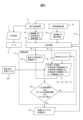
- FIG. 2 is a diagram showing the block configuration and processing flow of the drive control system for the railway vehicle power converter according to the first embodiment.
- the computing device 11 receives the semiconductor element temperature history 8 (T1) during actual operation from the power converter 2 and the operation history 9 during actual operation from the vehicle information device 6 via the transmission device 5.
- the calculation device 11 then calculates the current semiconductor element damage level 12 (D1) based on the semiconductor element temperature history 8 (T1) during actual operation.
- the semiconductor element damage level refers to the degree of element degradation caused by stress due to heat (temperature rise).
- the calculation device 11 also assumes that the operation history 9 during actual operation will be repeated during the planned operation period of the railway vehicle 1, and calculates the semiconductor element temperature history 14 (T2), semiconductor element damage degree 15 (D2), semiconductor element power consumption 16 (Ps), and motor power consumption 17 (Pm) as future predicted values based on the operation history 9 during actual operation.
- the future predicted values of the semiconductor element temperature history 14 (T2), semiconductor element damage degree 15 (D2), semiconductor element power consumption 16 (Ps), and motor power consumption 17 (Pm) are abbreviated as the future semiconductor element temperature history 14 (T2), future semiconductor element damage degree 15 (D2), future semiconductor element power consumption 16 (Ps), and future motor power consumption 17 (Pm), respectively.
- the period (cycle) of processing execution in the computing device 11 is assumed to be a processing cycle that is executed after a certain amount of time has elapsed, for example, once a month, once every three months, or once every six months.
- carrier pattern judgment 18 is performed.
- thresholds are set for the temperature and damage level of the semiconductor element so as not to cause element destruction within the planned operation period.
- the conditions for carrier pattern judgment 18 are that the future semiconductor element temperature history 14 (T2) is "T2 ⁇ temperature threshold” for the judgment of the temperature of the semiconductor element, and the sum (D1+D2) of the current semiconductor element damage level 12 (D1) and the future semiconductor element damage level 15 (D2) is "D1+D2 ⁇ damage level threshold” for the judgment of the damage level of the semiconductor element, and the sum (Ps+Pm) of the future semiconductor element power consumption 16 (Ps) and the future motor power consumption 17 (Pm) is the minimum (“Ps+Pm: minimum").
- the calculation device 11 If the changed carrier pattern 13 satisfies the above three judgment conditions (Yes), the calculation device 11 outputs an optimal carrier pattern change command 10 as the optimal control parameter and transmits it to the transmission device 5. If it does not satisfy the conditions (No), the carrier pattern is changed.
- the transmission device 5 sends an optimal carrier pattern change command 10 to the power converter 2, and the power converter 2 outputs AC power 7 to the motor 4 using this optimal carrier pattern.
- the semiconductor element temperature history 8 (T1) during actual operation may use output values from temperature sensors installed in the multiple semiconductor elements that make up the power converter 2, or may use values obtained by performing a predetermined calculation on output values from temperature sensors installed in other components such as a cooler (not shown) to which the semiconductor elements are attached.
- the actual operation history 9 is a time history of the vehicle position, vehicle running speed, vehicle notch, vehicle outside temperature, vehicle occupancy rate, motor current mounted on the vehicle, and carrier frequency of a power converter mounted on the vehicle, etc., related to the railway vehicle 1.
- the vehicle outside temperature may be detected using a temperature detection means installed on the railway vehicle 1, or observation data from a meteorological station may be used.
- the vehicle occupancy rate may be obtained from another management system.
- the frequency of outputting the optimum carrier pattern change command 10 is not limited.
- FIG. 3 is a diagram showing the carrier pattern, which is one of the control parameters of the power converter 2 in Examples 1 to 3.
- the changed carrier pattern 13 changes the carrier frequency in the asynchronous PWM region 20, and changes the modulation rate to change the number of pulses in the synchronous PWM region 21. This changes the carrier pattern.
- the carrier pattern is changed within a range that does not cause induction interference or motor control failure.
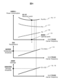
- Fig. 4 and Fig. 5 are diagrams showing the relationship between the power consumption, the semiconductor element temperature, and the degree of damage to the semiconductor element, respectively, and the carrier frequency in Examples 1 to 3.
- the upper graph shows the power consumption
- the middle graph shows the semiconductor element temperature
- the lower graph shows the degree of damage.
- the power consumption is the sum (Ps+Pm) of the future semiconductor element power consumption 16 (Ps) and the future motor power consumption 17 (Pm) (hereinafter referred to as "future power consumption (Ps+Pm)").
- the carrier frequency increases, the number of switching times of the semiconductor elements increases, and the loss, i.e., the future semiconductor element power consumption 16 (Ps), increases.
- the harmonic loss of the motor 4 decreases, and the future motor power consumption 17 (Pm) decreases.
- the sum of the two, the future power consumption (Ps+Pm) is a minimum value for the carrier frequency.
- the maximum value (max) of the future semiconductor element temperature history 14 (T2) and the sum (D1+D2) of the current and future semiconductor element damage degrees 12 and 15 increase with an increase in the carrier frequency, which corresponds to an increase in the loss of the semiconductor element.
- threshold values hereinafter referred to as the "temperature threshold” and “damage threshold" are set for the temperature and damage degree of the semiconductor element so as not to cause element destruction within the planned operation period.
- carrier frequency A at which future power consumption (Ps + Pm) is at a minimum value is a frequency that is lower than both the carrier frequency at which the maximum value (max) of future semiconductor element temperature history 14 (T2) coincides with the temperature threshold value, and the carrier frequency at which the sum (D1 + D2) of current and future semiconductor element damage levels 12 and 15 coincides with the damage level threshold value.
- carrier frequency A at which future power consumption (Ps+Pm) is minimized becomes the optimal value for reducing future power consumption (Ps+Pm), and is output as optimal carrier pattern change command 10.
- the carrier frequency at which the future power consumption (Ps+Pm) is a minimum is a frequency higher than carrier frequency B at which the sum (D1+D2) of the present and future semiconductor element damage levels 12 and 15 coincides with the damage level threshold.
- carrier frequency B where the sum (D1+D2) of the present and future semiconductor element damage levels 12 and 15 matches the damage level threshold becomes the optimal value for reducing the future power consumption (Ps+Pm), and is output as optimal carrier pattern change command 10.
- Example 1 the semiconductor element temperature, the semiconductor element damage level, and the power consumption can be calculated as future predicted values, and an optimal value can be calculated that reduces the power consumption within a threshold value that does not cause element failure. This makes it possible to reduce the power consumption of a railway vehicle according to the actual operating conditions, within a range that does not cause the semiconductor elements to overheat or become damaged. For example, even if the train runs under conditions that were not anticipated at the time of design, the control parameters can be optimized each time, thereby minimizing the power consumption within a range that does not cause failure during the operating period.
- FIG. 6 is a diagram showing the block configuration and processing flow of a drive control system for a railcar power converter according to Example 2.
- Example 2 when the calculation device 11 calculates future prediction values, a railcar operating condition change scenario 22 is additionally input.
- the operation condition change scenario 22 may be, for example, at least one of the following for railroad vehicles: change in operating hours, fluctuation in passenger occupancy rate, change in route, change in driver, presence or absence of automated driving, and weather change. These changes in operating conditions are also reflected in the calculation of future predicted values.
- the method according to the second embodiment makes it possible to reduce the power consumption of railway vehicles according to actual operating conditions, in response to anticipated future changes in operating conditions, without causing overheating or damage to semiconductor elements.
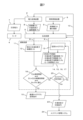
- FIG. 7 is a diagram showing the block configuration and processing flow of a drive control system for a railway vehicle power converter according to a third embodiment.
- the third embodiment also takes into consideration how to deal with the case where an appropriate solution is not obtained in the carrier pattern determination 18.
- a semiconductor element replacement command 23 is output to the maintenance management system 24 to prompt replacement of the semiconductor element.
- the number of times that the carrier pattern determination 18 is performed in one processing loop in the computing device 11 is limited to a predetermined number N, thereby making an output determination 25 of the semiconductor element replacement command 23.
- the method of output determination is not limited to this.
- the method according to the third embodiment makes it possible to replace semiconductor elements before they are damaged during operation, thereby making it possible to prevent unexpected failures.
Landscapes
- Engineering & Computer Science (AREA)
- Power Engineering (AREA)
- Transportation (AREA)
- Mechanical Engineering (AREA)
- Life Sciences & Earth Sciences (AREA)
- Sustainable Development (AREA)
- Sustainable Energy (AREA)
- Electric Propulsion And Braking For Vehicles (AREA)
- Inverter Devices (AREA)
- Control Of Electric Motors In General (AREA)
Abstract
Description
特許文献1には、電源からの電力を変換して電気車の負荷に電力を供給する電力変換部と、電力変換部を冷却する冷却部と、電力変換部をPWM制御する制御部を備え、制御部は、電気車の位置、電力変換部の温度、電気車制御装置の内部の温度、外気温又は電気車の乗車率のいずれか少なくとも1つ以上のパラメータに基づいて、PWM制御のキャリア周波数、キャリアパルス数又は電力変換部の出力電力を変更する構成が開示されている。かかる従来技術によれば、適切な冷却性能を有し、小型かつ低コストな電気車制御装置を提供する効果が期待される。
上記した以外の課題、構成および効果は、以下の実施をするための形態における説明により明らかにされる。
伝送装置5は、実稼働での半導体素子温度履歴8および実稼働での運行履歴9を演算装置11に送信する。
また、演算装置11は、鉄道車両1の床下に設置する構成でもよく、その場合には、伝送装置5を介することなく、電力変換器2および車両情報装置6それぞれから直に、実稼働での半導体素子温度履歴8および実稼働での運行履歴9を有線により受信する。
そして、演算装置11は、実稼働での半導体素子温度履歴8(T1)を基にして、現在の半導体素子損傷度12(D1)を演算する。ここで、半導体素子損傷度とは、熱(温度上昇)による応力に伴う素子の劣化度合いを意味する。
そしてまた、最適キャリアパタン変更指令10を出力する頻度は、限定されない。
この場合には、将来の消費電力(Ps+Pm)が極小値となるキャリア周波数Aが、将来の消費電力(Ps+Pm)を低減するための最適値となり、最適キャリアパタン変更指令10として出力されることになる。
したがって、図5のように、将来の消費電力(Ps+Pm)が極小値となるキャリア周波数では、将来の半導体素子損傷度が損傷度閾値よりも大きくなる。そのため、現在と将来の半導体素子損傷度12と15との合計(D1+D2)が損傷度閾値と一致するキャリア周波数Bが、将来の消費電力(Ps+Pm)を低減するための最適値となり、最適キャリアパタン変更指令10として出力されることになる。
Claims (13)
- 鉄道車両が搭載するモータに電力を供給する電力変換器の駆動制御システムであって、
複数の半導体素子から構成される前記電力変換器を駆動制御する指令を出力する演算装置を備え、
前記演算装置は、
実稼働での前記半導体素子の温度履歴を基にして当該半導体素子の現在の損傷度を演算し、また、実稼働での前記鉄道車両の運行履歴を基にして前記半導体素子の将来の温度履歴予測値および前記半導体素子の将来の損傷度予測値を演算し、更に、
前記半導体素子の将来の温度履歴予測値、前記半導体素子の現在の損傷度および前記半導体素子の将来の損傷度予測値に基づいて制御パラメータを選定し、当該制御パラメータを用いて前記指令を出力する
ことを特徴とする駆動制御システム。 - 請求項1に記載の駆動制御システムであって、
前記演算装置は、
実稼働での前記鉄道車両の運行履歴を基にして前記半導体素子の将来の消費電力予測値および前記モータの将来の消費電力予測値を演算し、
前記半導体素子の将来の温度履歴予測値が所定の温度閾値以下で、かつ、前記半導体素子の現在の損傷度および前記半導体素子の将来の損傷度予測値に基づく前記半導体素子の損傷度が所定の損傷度閾値以下となる条件で、当該半導体素子の将来の消費電力予測値および前記モータの将来の消費電力予測値に基づいて前記制御パラメータを選定する
ことを特徴とする駆動制御システム。 - 請求項1または請求項2に記載の駆動制御システムであって、
前記演算装置を、地上側設備としてまたは前記鉄道車両の車上側に備え、前記地上側設備として備える場合には、当該演算装置と前記電力変換器との間のデータを送受する伝送装置を備える
ことを特徴とする駆動制御システム。 - 請求項1から請求項3のいずれか1項に記載の駆動制御システムであって、
前記制御パラメータは、前記電力変換器を駆動するためのキャリアパタンである
ことを特徴とする駆動制御システム。 - 請求項1から請求項4のいずれか1項に記載の駆動制御システムであって、
実稼働での前記鉄道車両の運行履歴は、当該鉄道車両に関して、位置、走行速度、ノッチ、外気温度、乗車率、前記モータの電流および前記電力変換器のキャリア周波数、の各時間履歴の内の所定数以上の時間履歴である
ことを特徴とする駆動制御システム。 - 請求項1から請求項5のいずれか1項に記載の駆動制御システムであって、
実稼働での前記鉄道車両の運行履歴に対し、当該鉄道車両の運行条件が変更された場合の運行条件変更シナリオを用いて、前記半導体素子の将来の、温度履歴予測値、損傷度予測値および消費電力予測値、並びに前記モータの将来の消費電力予測値、を演算する
ことを特徴とする駆動制御システム。 - 請求項6に記載の駆動制御システムであって、
前記運行条件変更シナリオは、前記鉄道車両に関して、運行時間の変更、乗車率の変動、走行路線の変更、運転士の変更および自動運転化の有無、並びに、気候の変動、の内少なくとも一つ以上である
ことを特徴とする駆動制御システム。 - 請求項1から請求項7のいずれか1項に記載の駆動制御システムであって、
前記演算装置は、前記制御パラメータを選定できない場合には、前記半導体素子の交換指令を生成する
ことを特徴とする駆動制御システム。 - 鉄道車両が搭載するモータに電力を供給する電力変換器の駆動制御方法であって、
複数の半導体素子から構成される前記電力変換器に対して、
実稼働での前記半導体素子の温度履歴を取得し、当該温度履歴を基にして前記半導体素子の現在の損傷度を演算し、
実稼働での前記鉄道車両の運行履歴を取得し、当該運行履歴を基にして前記半導体素子の将来の温度履歴予測値および前記半導体素子の将来の損傷度予測値を演算し、
前記半導体素子の将来の温度履歴予測値、前記半導体素子の現在の損傷度および前記半導体素子の将来の損傷度予測値に基づいて制御パラメータを選定し、
前記制御パラメータを用いて前記電力変換器を駆動制御する指令を出力する
ことを特徴とする駆動制御方法。 - 請求項9に記載の駆動制御方法であって、
前記運行履歴を基にして前記半導体素子の将来の消費電力予測値および前記モータの将来の消費電力予測値を演算し、
前記制御パラメータを、前記半導体素子の将来の温度履歴予測値が所定の温度閾値以下で、かつ、前記半導体素子の現在の損傷度および前記半導体素子の将来の損傷度予測値に基づく前記半導体素子の損傷度が所定の損傷度閾値以下となる条件で、当該半導体素子の将来の消費電力予測値および前記モータの将来の消費電力予測値に基づいて選定する
ことを特徴とする駆動制御方法。 - 請求項9または請求項10に記載の駆動制御方法であって、
前記制御パラメータは、前記電力変換器を駆動するためのキャリアパタンである
ことを特徴とする駆動制御方法。 - 請求項9から請求項11のいずれか1項に記載の駆動制御方法であって、
実稼働での前記鉄道車両の運行履歴に対し、当該鉄道車両の運行条件が変更された場合の運行条件変更シナリオを用いて、前記半導体素子の将来の、温度履歴予測値、損傷度予測値および消費電力予測値、並びに前記モータの将来の消費電力予測値、を演算する
ことを特徴とする駆動制御方法。 - 請求項9から請求項12のいずれか1項に記載の駆動制御方法であって、
前記制御パラメータを選定できない場合には、前記半導体素子を交換する指令を生成する
ことを特徴とする駆動制御方法。
Priority Applications (1)
| Application Number | Priority Date | Filing Date | Title |
|---|---|---|---|
| GB2513053.5A GB2641690A (en) | 2023-06-20 | 2024-03-29 | Drive control system and drive control method for power converter or railway vehicle |
Applications Claiming Priority (2)
| Application Number | Priority Date | Filing Date | Title |
|---|---|---|---|
| JP2023101069A JP2025001463A (ja) | 2023-06-20 | 2023-06-20 | 鉄道車両用電力変換器の駆動制御システムおよび駆動制御方法 |
| JP2023-101069 | 2023-06-20 |
Publications (1)
| Publication Number | Publication Date |
|---|---|
| WO2024262124A1 true WO2024262124A1 (ja) | 2024-12-26 |
Family
ID=93935648
Family Applications (1)
| Application Number | Title | Priority Date | Filing Date |
|---|---|---|---|
| PCT/JP2024/013238 Ceased WO2024262124A1 (ja) | 2023-06-20 | 2024-03-29 | 鉄道車両用電力変換器の駆動制御システムおよび駆動制御方法 |
Country Status (3)
| Country | Link |
|---|---|
| JP (1) | JP2025001463A (ja) |
| GB (1) | GB2641690A (ja) |
| WO (1) | WO2024262124A1 (ja) |
Citations (4)
| Publication number | Priority date | Publication date | Assignee | Title |
|---|---|---|---|---|
| JP2018026946A (ja) * | 2016-08-10 | 2018-02-15 | 株式会社日立製作所 | 電力変換装置、電力変換装置の寿命診断方法、電力変換装置のスイッチング素子温度検出方法および電力変換システム |
| JP2019047695A (ja) * | 2017-09-06 | 2019-03-22 | 株式会社日立製作所 | 電力変換装置、電動機制御システム、および電力変換装置の診断方法 |
| JP2019075891A (ja) * | 2017-10-16 | 2019-05-16 | 株式会社日立製作所 | 電力変換装置 |
| JP2021046170A (ja) * | 2019-09-20 | 2021-03-25 | 株式会社デンソー | 車両用の電力変換装置 |
-
2023
- 2023-06-20 JP JP2023101069A patent/JP2025001463A/ja active Pending
-
2024
- 2024-03-29 WO PCT/JP2024/013238 patent/WO2024262124A1/ja not_active Ceased
- 2024-03-29 GB GB2513053.5A patent/GB2641690A/en active Pending
Patent Citations (4)
| Publication number | Priority date | Publication date | Assignee | Title |
|---|---|---|---|---|
| JP2018026946A (ja) * | 2016-08-10 | 2018-02-15 | 株式会社日立製作所 | 電力変換装置、電力変換装置の寿命診断方法、電力変換装置のスイッチング素子温度検出方法および電力変換システム |
| JP2019047695A (ja) * | 2017-09-06 | 2019-03-22 | 株式会社日立製作所 | 電力変換装置、電動機制御システム、および電力変換装置の診断方法 |
| JP2019075891A (ja) * | 2017-10-16 | 2019-05-16 | 株式会社日立製作所 | 電力変換装置 |
| JP2021046170A (ja) * | 2019-09-20 | 2021-03-25 | 株式会社デンソー | 車両用の電力変換装置 |
Also Published As
| Publication number | Publication date |
|---|---|
| GB2641690A (en) | 2025-12-10 |
| JP2025001463A (ja) | 2025-01-08 |
Similar Documents
| Publication | Publication Date | Title |
|---|---|---|
| KR101039678B1 (ko) | 하이브리드 차량의 전력변환장치 냉각 제어 방법 | |
| CN102449281B (zh) | 用于机动车辆的冷却装置 | |
| JP4349447B2 (ja) | インバータ制御装置および車両 | |
| JP5182310B2 (ja) | 鉄道編成車両の駆動システム | |
| US8179084B2 (en) | Variable-speed-drive system for a grid blower | |
| JP4973813B2 (ja) | 推進制御装置 | |
| US20210305606A1 (en) | Controller, controlling method, and record medium | |
| TWI770019B (zh) | 電車用電力轉換控制裝置 | |
| JP2008221991A (ja) | 制御用サブユニットおよび制御用メインユニット | |
| JP2014529985A (ja) | 電動車両のための冷却システム | |
| GB2401203A (en) | Thermal protection system for high output vehicle alternator | |
| JP2008259282A (ja) | 電源装置 | |
| KR20180096088A (ko) | 플러그 인 차량의 충전제어방법 | |
| JP2025001463A (ja) | 鉄道車両用電力変換器の駆動制御システムおよび駆動制御方法 | |
| JP2015033182A (ja) | 半導体電力変換器の冷却システム | |
| JP2003274509A (ja) | 電力変換装置 | |
| JP5352731B2 (ja) | 鉄道編成車両の駆動システム | |
| JP7327036B2 (ja) | 車両用の電力変換装置 | |
| JP5373644B2 (ja) | 編成車両の制御方法及び制御装置 | |
| KR20140094641A (ko) | 전력 변환 장치 | |
| CN107762612A (zh) | 电机的多个变流器的符合需求的冷却 | |
| JP2001186775A (ja) | 電気車用制御装置 | |
| JP7580294B2 (ja) | 電動車両の冷却装置 | |
| JP5790483B2 (ja) | エレベータの制御装置 | |
| JP7001134B2 (ja) | 電力変換装置、電気鉄道システム |
Legal Events
| Date | Code | Title | Description |
|---|---|---|---|
| 121 | Ep: the epo has been informed by wipo that ep was designated in this application |
Ref document number: 24825534 Country of ref document: EP Kind code of ref document: A1 |
|
| ENP | Entry into the national phase |
Ref document number: 202513053 Country of ref document: GB Kind code of ref document: A Free format text: PCT FILING DATE = 20240329 |
|
| WWE | Wipo information: entry into national phase |
Ref document number: 2513053.5 Country of ref document: GB |
|
| WWE | Wipo information: entry into national phase |
Ref document number: 112025000139237 Country of ref document: IT |
|
| WWP | Wipo information: published in national office |
Ref document number: 2513053.5 Country of ref document: GB |
|
| NENP | Non-entry into the national phase |
Ref country code: DE |