WO2024261988A1 - プレス成形装置 - Google Patents
プレス成形装置 Download PDFInfo
- Publication number
- WO2024261988A1 WO2024261988A1 PCT/JP2023/023214 JP2023023214W WO2024261988A1 WO 2024261988 A1 WO2024261988 A1 WO 2024261988A1 JP 2023023214 W JP2023023214 W JP 2023023214W WO 2024261988 A1 WO2024261988 A1 WO 2024261988A1
- Authority
- WO
- WIPO (PCT)
- Prior art keywords
- cam
- die
- cam driver
- driver
- slide
- Prior art date
- Legal status (The legal status is an assumption and is not a legal conclusion. Google has not performed a legal analysis and makes no representation as to the accuracy of the status listed.)
- Ceased
Links
Images




Classifications
-
- B—PERFORMING OPERATIONS; TRANSPORTING
- B21—MECHANICAL METAL-WORKING WITHOUT ESSENTIALLY REMOVING MATERIAL; PUNCHING METAL
- B21D—WORKING OR PROCESSING OF SHEET METAL OR METAL TUBES, RODS OR PROFILES WITHOUT ESSENTIALLY REMOVING MATERIAL; PUNCHING METAL
- B21D45/00—Ejecting or stripping-off devices arranged in machines or tools dealt with in this subclass
Definitions
- the present invention relates to an improvement to a press forming device used to form a formed part, including a negative angle portion, in a blank material.
- Patent Document 1 discloses a drawing forming device that performs forming processing on a work panel, including a gently sloping surface and a steeply sloping surface continuing therefrom.
- This drawing forming device is equipped with an upper mold with a cylinder, a lower mold with a concave forming surface corresponding to the gently sloping surface and the steeply sloping surface, an upper mold cushion ring with an inclined guide surface that can be displaced vertically via the cylinder, a lower mold cushion ring that abuts against the upper mold or the upper mold cushion ring and can be displaced vertically within a restricted area, and a pull-up cam that is disposed inside the upper mold cushion ring and has a convex forming surface that corresponds to the concave forming surface and a cam surface that slides against the guide surface.
- the above-mentioned squeeze forming device performs a first forming process in which the upper mold is lowered while biasing the upper mold cushion ring via a cylinder, pushing down the lower mold cushion ring and pressing the upper mold cushion ring against the lower mold cushion ring, and a second forming process in which the upper mold is further lowered, the cylinder is contracted, and the shifting cam slides along the guide surface, pressing the convex forming surface of the shifting cam against the concave forming surface of the lower mold.
- a press forming device equipped with a cam mechanism is used to form the steeply inclined portion described in Patent Document 1, i.e., a vertical wall-like negative corner portion that is difficult to form with only the up and down movement of the upper die.
- the cam slide moves forward horizontally while descending to form the negative corner portion, but to more reliably prevent cracks and the like in the negative corner portion, it is desirable for the forward movement angle of the cam slide to be small.
- the conventional press forming device described above does not reduce the forward movement angle of the pull-up cam (cam slide), but instead uses a floating die structure in which the pull-up cam is suspended from the upper die via a cylinder, and in the final stage, the cylinder is contracted to advance the pull-up cam, forming a negative corner (steeply inclined surface) with the pull-up cam, thereby preventing cracks in the negative corner.
- the present invention was made in consideration of the above-mentioned conventional situation, and aims to provide a press forming device that does not use a floating die structure, but instead uses a cam slide and multiple cam drivers that are directly driven in conjunction with the lowering movement of the upper die, thereby reducing the forward movement angle of the cam slide to prevent cracking of negative corners, and also simplifies the device structure.
- the press forming device is a press forming device for forming a formed part including a negative angle part in a blank material, and includes a lower die and an upper die that can be raised and lowered relative to the lower die.
- the lower die includes a punch for forming a formed part in the blank material, and a blank holder for holding the blank material prior to forming the blank material.
- the upper die includes a die facing the punch and blank holder, a cam slide that is held so as to be able to advance and retreat toward the inside of the die in which the punch is arranged, and advances to form a negative angle part between the punch, and an upper cam driver that is arranged on the outside of the die of the cam slide and held so as to be able to advance and retreat toward the inside of the die.
- the lower die also includes a lower cam driver that is arranged in a position corresponding to between the cam slide and the upper cam driver and held so as to be able to advance and retreat toward the inside of the die, and a fixed cam driver that is arranged in an immobile state outside the die of the lower cam driver.
- the press forming device is characterized in that, as the upper die descends, the fixed cam driver advances the cam slide toward the inside of the die via the upper cam driver and the lower cam driver.
- the negative angle in the above configuration does not indicate a specific angle, but is a vertical wall-like part that is difficult to mold by the up and down movement of the upper mold alone, and includes, for example, a horizontal concave part or an overhanging part.
- the press forming device of the present invention uses a cam slide and multiple cam drivers that are directly driven in conjunction with the lowering movement of the upper die to reduce the forward movement angle of the cam slide, preventing cracks in negative corners, while also simplifying the device structure and ensuring sufficient clearance between the upper die that has reached top dead center and the blank conveying device.
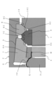
- FIG. 1 is a cross-sectional view showing a state in which an upper die is at top dead center in a first embodiment of a press forming apparatus according to the present invention.
- FIG. 2 is a cross-sectional view of the main part showing a state immediately before the upper die reaches the bottom dead center subsequent to FIG. 1 .
- FIG. 3 is a cross-sectional view of the main part showing a state in which the upper die has reached the bottom dead center subsequent to FIG. 2 .
- FIG. 4 is a cross-sectional view of the main part showing a state after the upper die has been raised, subsequent to FIG. 3 .
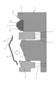
- FIG. 11 is a cross-sectional view showing a state in which an upper die is at the top dead center in a second embodiment of the press forming apparatus according to the present invention.
- FIG. 6 is a cross-sectional view of the main part showing a state immediately before the upper die reaches the bottom dead center, subsequent to FIG. 5 .
- FIG. 7 is a cross-sectional view of the main part showing a state in which the upper die has reached the bottom dead center, following FIG. 6 .
- FIG. 8 is a cross-sectional view of the main part showing a state after the upper die has been raised, subsequent to FIG. 7 .
- FIG. 11 is a cross-sectional view of a main part for explaining a third embodiment of a press forming apparatus according to the present invention.
- the press forming apparatus shown in Fig. 1 presses a blank material W shown by a solid line in the figure to form a formed portion Q including a negative corner portion P shown by a dotted line in the figure.
- the negative corner portion P in the illustrated example is a part of the formed portion Q that bulges upward, and has a concave shape facing diagonally upward (upper right in the figure).
- the press molding device is equipped with a lower die 1 that is arranged on the bolster side of a press machine (not shown), and a lower die 2 that is arranged on the slide side of the press machine. This allows the upper die 2 to be raised and lowered relative to the lower die 1.
- the position of the punch is used as the reference, and the direction toward the punch is referred to as the inside of the die, and the opposite direction is referred to as the outside of the die.
- the lower die 1 is equipped with a punch 3 that forms a formed portion Q including a negative corner portion P in the blank material W, and a blank holder 4 that holds the blank material W prior to forming the blank material W.
- the blank holder 4 is disposed so as to surround the punch 3, and is elastically held in a position where its upper surface is higher than the upper surface of the punch 3 by a retainer 5 shown by an imaginary line in the figure.
- the upper die 2 is equipped with a die 6 that faces the punch 3 and blank holder 4, a cam slide 7 that is held so that it can move back and forth toward the inside of the die in which the punch 3 is placed and moves forward to form a negative angle P between the punch 3, and an upper cam driver 8 that is placed on the outside of the die of the cam slide 7 and is held so that it can move back and forth toward the inside of the die.
- the cam slide 7 is elastically held by a retainer (not shown) relative to the die 6 so as to maintain a retracted position outside the mold, and can move forward against the retainer toward the inside of the mold when the upper mold 2 descends during molding.
- the cam slide 7 has a convex curved surface 7P corresponding to the negative corner P at the lower end on its forward moving side (left side in Figure 1), and a downwardly inclined cam surface 7C at the end on the backward moving side.
- the cam slide 7 is held slidably between the main body of the die 6 and the holding portion 6A, which is part of the main body.
- the holding portion 6A in the illustrated example has a part of the die face, which is the forming surface of the die 6, and presses and holds the blank W together with the blank holder 4, and forms the end of the formed portion Q that is continuous with the lower side of the negative corner portion P, together with the punch 3.
- the upper cam driver 8 like the cam slide 7, is elastically held by a retainer (not shown) relative to the die 6 so as to maintain a retracted position outside the mold, and can move forward against the retainer toward the inside of the mold during molding when the upper mold 2 descends.
- the upper cam driver 8 has downwardly inclined cam surfaces 8C, 8C on the inside and outside of the mold.
- the lower mold 1 is equipped with a lower cam driver 9 that is arranged at a position corresponding to the position between the cam slide 7 and the upper cam driver 8 and is held so that it can move forward and backward toward the inside of the mold, and a fixed cam driver 10 that is immobile and positioned outside the mold of the lower cam driver 9.
- the lower cam driver 9 is elastically held by a retainer (not shown) so as to maintain a retracted position outside the lower mold 1, and can move forward against the retainer toward the inside of the mold when the upper mold 2 descends during molding.
- the lower cam driver 9 has upwardly facing inclined cam surfaces 9C, 9C on its inside and outside of the mold that correspond respectively to the inclined cam surface C of the cam slide 7 and the inclined cam surface 8C on the inside of the mold of the upper cam driver 8.
- the fixed cam driver 10 may be integral with the lower die 1 as shown in the figure, or may be a separate body fixed to the lower die 1, and has an upwardly facing inclined cam surface 10C on the inside of the die that corresponds to the inclined cam surface 8C on the outside of the die of the upper cam driver 8.
- the cam slide 7 is held in the die 6 so that it can move linearly back and forth, and the combination of the cam slide 7 and lower cam driver 9, the combination of the lower cam driver 9 and upper cam driver 8, and the combination of the upper cam driver 8 and fixed cam driver 10 each have inclined cam surfaces (7C, 8C, 9C, 10C) that come into contact with each other.
- the sliding surface S between the die 6 and the cam slide 7 is an inclined surface that has an upward slope toward the inside of the mold. As a result, the cam slide 7 is driven at a composite cam angle, which is the sum of the angle of the inclined cam surface 7C and the angle of the sliding surface S.
- the fixed cam driver 10 advances the cam slide 7 toward the inside of the die via the upper cam driver 8 and the lower cam driver 9.
- the operation of the press molding device during molding is specifically described below.
- the press forming device sets a flat blank material W in the blank holder 4, and then the upper die 2 is lowered by the sliding of the press machine. As the upper die 2 is lowered, the press forming device presses and holds the outer periphery of the blank material W between the blank holder 4 and the die 6, and then, while pressing down the blank holder 4, squeezes the blank material W by bulging it upward with the punch 3.
- the fixed cam driver 10, upper cam driver 8, lower cam driver 9, and cam slide 7 come into contact with each other at their respective inclined cam surfaces 10C, 8C, 9C, and 7C, as shown in FIG. 2 (the part within the dashed line in FIG. 1).
- the upper cam driver 8, lower cam driver 9, and cam slide 7 are all maintained in the retracted position by retainers. Therefore, the die 6 and the blank material W are separated, and the cam slide 7 and the blank material W are also separated.
- the press molding device clamps the blank material W between the die 6 and the punch 3 to form the molded portion Q, and at the same time forms a concave negative angle portion P between the punch 3 and the convex curved surface 7P of the cam slide 7 that has advanced toward the inside of the mold.
- Figure 3 shows the position of the cam slide 7 in Figure 2 (virtual line) and the forward movement angle ⁇ of the cam slide 7.
- the forward movement angle ⁇ is the angle between the horizontal line and the diagonal movement direction of the cam slide 7 that advances while descending.
- the press forming device raises the upper die 2, and in the upper die 2, the lower cam driver 9 and cam slide 7 both return to their retracted positions, and in the lower die 1, the blank holder 4 returns to its raised position and the lower cam driver 9 returns to its retracted position. Then, as shown in FIG. 4, the press forming device releases the blank W having the formed portion Q including the negative corner portion P. The blank W is then transported out by a transport device (not shown).
- the fixed cam driver 10 advances the upper cam driver 8, lower cam driver 9, and cam slide 7 in unison, and the cam slide 7 forms a negative angle P in the blank W.
- This type of press forming device can ensure a larger advance distance for the cam slide 7 than, for example, when the cam slide of the upper die 2 is advanced by a single cam driver fixed to the lower die 1. In other words, the press forming device can ensure a larger advance distance for the cam slide 7 for a given amount of descent of the lower die 2, so the advance angle ⁇ of the cam slide 7 is smaller.
- the above press forming device can prevent cracking of the negative corner P by reducing the forward movement angle ⁇ of the cam slide 7 through the cam slide 7 and multiple cam drivers 8-10, which are directly driven in conjunction with the downward movement of the upper die 2. Furthermore, because the above press forming device drives the cam slide 7 through cooperation between the upper and lower cam drivers 8-10, there is no need for a drive source, etc., required for a floating die structure, which makes it possible to simplify the device structure and also makes it easy to ensure sufficient clearance between the upper die 2, which has reached top dead center, and the conveying device for the blank material W.
- the above press molding device reduces the escape angle when the cam slide 7 retreats, so it is possible to ensure the volume of the mold escape portion of the die 6, specifically the volume of the portion of the holding portion 6A of the die 6 that faces the punch 3, and obtain sufficient mold strength. Furthermore, the above press molding device makes the sliding surface S between the die 6 and the cam slide 7 an inclined surface that slopes upward toward the inside of the mold, thereby making the forward and backward movement of the cam slide 7 smoother.
- the cam slide 7 and each cam driver 8-10 have inclined cam surfaces 7C-10C, and the cam slide 7 is configured to move linearly forward and backward relative to the die 6, which allows the forward and backward movement of the cam slide 7 and the upper and lower cam drivers 8, 9 to be made smoother.
- FIGS. 5 to 9 are diagrams illustrating second and third embodiments of the press molding device according to the present invention.
- the same components as those in the first embodiment are given the same reference numerals, and detailed descriptions are omitted.
- Second Embodiment 5 to 8 are diagrams illustrating a press-forming apparatus according to a second embodiment of the present invention.
- the press molding device shown in Fig. 5 has a basic configuration equivalent to that of the first embodiment, and has a structure in which the cam slide 7 is held in the die 6 so as to be able to advance and retreat in a curved manner along an arc having a rotation center below. Therefore, the sliding surface S between the die 6 and the cam slide 7 is a curved surface with a concave lower side, and the holding part 6A and the cam slide 7 also contact each other by a curved surface. Note that the above-mentioned arc and curved surface have a relatively large radius of curvature.
- the cam slide 7 has a downwardly extending hanging portion 7A, and at the lower end of the hanging portion 7A, an arc-shaped convex cam surface 7D that determines the center of rotation.
- the lower cam driver 9 of the lower mold 1 has a concave cam surface 9D on the inside of the mold that receives the convex cam surface 7D of the cam slide 7, and has an inclined cam surface 9C on the outside of the mold.
- the upper cam driver 8 and fixed cam driver 10 have the same inclined cam surfaces 8C, 10C as in the first embodiment.
- the press forming device sets a flat blank material W in the blank holder 4, and then the upper die 2 is lowered by the slide of the press machine.
- the fixed cam driver 10, upper cam driver 8, and lower cam driver 9 come into contact with each other at their respective inclined cam surfaces 10C, 8C, and 9C, and the concave cam surface 9D of the lower cam driver 9 comes into contact with the convex cam surface 7D of the cam slide 7.
- the upper cam driver 8, lower cam driver 9, and cam slide 7 are all maintained in the retracted position by the retainers.
- the upper cam driver 8 and the lower cam driver 9 advance due to the component forces generated by the respective inclined cam surfaces 10C, 8C, and 9C until the upper die 2 reaches the bottom dead center, and at the same time, the convex cam surface 7D of the cam slide 7 slides along an arc against the concave cam surface 9D of the lower cam driver 9.
- the press molding device molds the molded portion Q in the blank material W between the punch 3 and the die 6, while at the same time the cam slide 7 rotates and advances around the center of the arc of the convex cam surface 7D, molding a concave negative angle portion P between the convex curved surface 7P and the punch 3.
- the press molding device raises the upper die 2, and in the upper die 2, the lower cam driver 9 and cam slide 7 both return to their retracted positions, and in the lower die 1, the blank holder 4 returns to its raised position and the lower cam driver 9 returns to its retracted position, and the blank W having the formed portion Q including the negative corner portion P is released from the mold, as shown in Figure 8.
- the above press molding device can achieve the same effects and advantages as the first embodiment, and in particular, by adopting a structure in which the cam slide 7 is held so that it can move forward and backward in a curved manner along an arc with a rotation center below, the escape angle when the cam slide 7 retreats can be reduced, ensuring the volume of the mold escape portion of the die 6 and providing sufficient mold strength.
- Third Embodiment 9 has the same basic configuration as the first embodiment, and in the lower die 1, a second lower cam driver 19 that can advance and retreat toward the inside of the die is disposed outside the lower cam driver 9. Furthermore, in the upper die 2 of the press forming device, the fixed cam driver 10 disposed in the lower die 1 in the first embodiment is disposed outside the upper cam driver 8.
- the second lower cam driver 19 has upwardly inclined cam surfaces 19C, 19C on the inside and outside of the die.
- the fixed cam driver 10 advances the cam slide 8 via the first lower cam driver 19, the upper cam driver 8, and the lower cam driver 9 inside the die, forming the formed portion Q in the blank material W between the punch 3 and the die 6, while simultaneously forming the negative angle portion P between the punch 3 and the cam slide 7.
- the above press molding device can achieve the same effects and advantages as the previous embodiments, and by increasing the number of movable cam drivers 8, 9, and 19, the forward movement distance of the cam slide 7 can be increased, thereby reducing the forward movement angle ⁇ of the cam slide 7 and improving the function of preventing thinning and cracking of the negative corner portion P.
- the configuration of the press molding device according to the present invention is not limited to the above-mentioned embodiments, but can be modified as appropriate without departing from the gist of the present invention, and the configurations of the various embodiments can be combined.
Landscapes
- Engineering & Computer Science (AREA)
- Mechanical Engineering (AREA)
- Mounting, Exchange, And Manufacturing Of Dies (AREA)
- Shaping Metal By Deep-Drawing, Or The Like (AREA)
Priority Applications (3)
| Application Number | Priority Date | Filing Date | Title |
|---|---|---|---|
| JP2025527368A JPWO2024261988A1 (https=) | 2023-06-22 | 2023-06-22 | |
| PCT/JP2023/023214 WO2024261988A1 (ja) | 2023-06-22 | 2023-06-22 | プレス成形装置 |
| CN202380099295.XA CN121285435A (zh) | 2023-06-22 | 2023-06-22 | 冲压成型装置 |
Applications Claiming Priority (1)
| Application Number | Priority Date | Filing Date | Title |
|---|---|---|---|
| PCT/JP2023/023214 WO2024261988A1 (ja) | 2023-06-22 | 2023-06-22 | プレス成形装置 |
Publications (1)
| Publication Number | Publication Date |
|---|---|
| WO2024261988A1 true WO2024261988A1 (ja) | 2024-12-26 |
Family
ID=93935216
Family Applications (1)
| Application Number | Title | Priority Date | Filing Date |
|---|---|---|---|
| PCT/JP2023/023214 Ceased WO2024261988A1 (ja) | 2023-06-22 | 2023-06-22 | プレス成形装置 |
Country Status (3)
| Country | Link |
|---|---|
| JP (1) | JPWO2024261988A1 (https=) |
| CN (1) | CN121285435A (https=) |
| WO (1) | WO2024261988A1 (https=) |
Citations (5)
| Publication number | Priority date | Publication date | Assignee | Title |
|---|---|---|---|---|
| JPH08197154A (ja) * | 1995-01-24 | 1996-08-06 | Honda Motor Co Ltd | ドアスキンのベンド加工装置 |
| JPH08243650A (ja) * | 1995-03-09 | 1996-09-24 | Toyota Motor Corp | 絞り成形方法 |
| JP2003205320A (ja) * | 2002-01-11 | 2003-07-22 | Toyota Motor Corp | プレス加工装置 |
| JP2015205308A (ja) * | 2014-04-21 | 2015-11-19 | トヨタ自動車東日本株式会社 | クランプ機構を有するワーク位置決め装置 |
| JP2021037536A (ja) * | 2019-09-05 | 2021-03-11 | 東プレ株式会社 | 絞り成形品の製造方法及びステアリングホールカバー |
-
2023
- 2023-06-22 JP JP2025527368A patent/JPWO2024261988A1/ja active Pending
- 2023-06-22 WO PCT/JP2023/023214 patent/WO2024261988A1/ja not_active Ceased
- 2023-06-22 CN CN202380099295.XA patent/CN121285435A/zh active Pending
Patent Citations (5)
| Publication number | Priority date | Publication date | Assignee | Title |
|---|---|---|---|---|
| JPH08197154A (ja) * | 1995-01-24 | 1996-08-06 | Honda Motor Co Ltd | ドアスキンのベンド加工装置 |
| JPH08243650A (ja) * | 1995-03-09 | 1996-09-24 | Toyota Motor Corp | 絞り成形方法 |
| JP2003205320A (ja) * | 2002-01-11 | 2003-07-22 | Toyota Motor Corp | プレス加工装置 |
| JP2015205308A (ja) * | 2014-04-21 | 2015-11-19 | トヨタ自動車東日本株式会社 | クランプ機構を有するワーク位置決め装置 |
| JP2021037536A (ja) * | 2019-09-05 | 2021-03-11 | 東プレ株式会社 | 絞り成形品の製造方法及びステアリングホールカバー |
Also Published As
| Publication number | Publication date |
|---|---|
| JPWO2024261988A1 (https=) | 2024-12-26 |
| CN121285435A (zh) | 2026-01-06 |
Similar Documents
| Publication | Publication Date | Title |
|---|---|---|
| CN107088618B (zh) | 一种斜楔式预延伸拉延模 | |
| JP2013078777A (ja) | プレス金型 | |
| CN206122528U (zh) | 一种可调角度钣金件折弯模具 | |
| CN201115865Y (zh) | 一种定位块结构和具有该定位块结构的斜楔结构 | |
| CN207521555U (zh) | 一种实现带负角翻边的模具结构 | |
| CN211276146U (zh) | 一种靠背边板成型模具 | |
| CN201127972Y (zh) | 浮动压料机构 | |
| WO2024261988A1 (ja) | プレス成形装置 | |
| JP4970900B2 (ja) | プレス加工法およびそれに用いる成形装置 | |
| CN221890679U (zh) | 一种汽车前地板加强板生产用冲压模具 | |
| KR20040007188A (ko) | 부각 성형형의 로터리 캠 이동 장치 | |
| CN119328136A (zh) | 双排异形齿轮粉末冶金生产用压制模具及其压制方法 | |
| CN110732576A (zh) | 一种汽车摆臂冲压件端孔翻孔模具及其翻孔方法 | |
| CN118305227A (zh) | 五金件自动化冲压设备 | |
| JP2000233232A (ja) | フランジ加工用プレス成形装置 | |
| CN209452655U (zh) | 一种洗衣机外壳模具 | |
| JP2756539B2 (ja) | 閉塞鍛造成形装置 | |
| CN210334017U (zh) | 抬料旋转负角成型机构 | |
| CN120532948B (zh) | 一种快速脱料与导正复合的汽车前地板冲压模具 | |
| JPH04190931A (ja) | ロッキング機構付き絞り型 | |
| JPH031084B2 (https=) | ||
| CN212884499U (zh) | 一种用于复杂零件折弯的级进模 | |
| CN106563736B (zh) | 水平推进式预包边机构 | |
| CN108687243A (zh) | 一种无闭锁压机实现闭锁功能的模具 | |
| CN220406821U (zh) | 一种侧修边侧冲孔负角回退结构 |
Legal Events
| Date | Code | Title | Description |
|---|---|---|---|
| 121 | Ep: the epo has been informed by wipo that ep was designated in this application |
Ref document number: 23942420 Country of ref document: EP Kind code of ref document: A1 |
|
| ENP | Entry into the national phase |
Ref document number: 2025527368 Country of ref document: JP Kind code of ref document: A |
|
| WWE | Wipo information: entry into national phase |
Ref document number: 2025527368 Country of ref document: JP |
|
| NENP | Non-entry into the national phase |
Ref country code: DE |