WO2024261924A1 - 空気調和システム - Google Patents
空気調和システム Download PDFInfo
- Publication number
- WO2024261924A1 WO2024261924A1 PCT/JP2023/023003 JP2023023003W WO2024261924A1 WO 2024261924 A1 WO2024261924 A1 WO 2024261924A1 JP 2023023003 W JP2023023003 W JP 2023023003W WO 2024261924 A1 WO2024261924 A1 WO 2024261924A1
- Authority
- WO
- WIPO (PCT)
- Prior art keywords
- unit
- refrigerant
- indoor unit
- shutoff
- indoor
- Prior art date
- Legal status (The legal status is an assumption and is not a legal conclusion. Google has not performed a legal analysis and makes no representation as to the accuracy of the status listed.)
- Ceased
Links
Images






Classifications
-
- F—MECHANICAL ENGINEERING; LIGHTING; HEATING; WEAPONS; BLASTING
- F24—HEATING; RANGES; VENTILATING
- F24F—AIR-CONDITIONING; AIR-HUMIDIFICATION; VENTILATION; USE OF AIR CURRENTS FOR SCREENING
- F24F11/00—Control or safety arrangements
- F24F11/30—Control or safety arrangements for purposes related to the operation of the system, e.g. for safety or monitoring
- F24F11/32—Responding to malfunctions or emergencies
- F24F11/36—Responding to malfunctions or emergencies to leakage of heat-exchange fluid
-
- F—MECHANICAL ENGINEERING; LIGHTING; HEATING; WEAPONS; BLASTING
- F24—HEATING; RANGES; VENTILATING
- F24F—AIR-CONDITIONING; AIR-HUMIDIFICATION; VENTILATION; USE OF AIR CURRENTS FOR SCREENING
- F24F11/00—Control or safety arrangements
- F24F11/50—Control or safety arrangements characterised by user interfaces or communication
- F24F11/52—Indication arrangements, e.g. displays
- F24F11/526—Indication arrangements, e.g. displays giving audible indications
-
- F—MECHANICAL ENGINEERING; LIGHTING; HEATING; WEAPONS; BLASTING
- F24—HEATING; RANGES; VENTILATING
- F24F—AIR-CONDITIONING; AIR-HUMIDIFICATION; VENTILATION; USE OF AIR CURRENTS FOR SCREENING
- F24F11/00—Control or safety arrangements
- F24F11/89—Arrangement or mounting of control or safety devices
Definitions
- This disclosure relates to air conditioning systems.
- Patent Document 1 discloses an air conditioning system configured such that when a refrigerant leak in an indoor unit is detected by a refrigerant sensor, sensor information is sent from the indoor unit to a relay side control unit, and an alarm is output by the relay side control unit that receives the sensor information, and the flow of refrigerant from the outdoor unit to the indoor unit is blocked.
- JP 2018-77040 A if a communication abnormality occurs between the indoor unit and the relay side control unit, it is not possible to output an alarm indicating a refrigerant leak. Furthermore, a single refrigerant sensor and alarm are not sufficient safety measures.
- This disclosure is made to explain an embodiment that solves the problems described above, and its purpose is to strengthen safety measures against refrigerant leaks compared to conventional methods.
- the present disclosure relates to an air conditioning system.
- the air conditioning system includes a heat source unit, a first indoor unit having a first heat exchanger that exchanges heat with the heat source unit via a refrigerant and that blows conditioned air into a first air-conditioned space, a first shutoff unit having a first shutoff valve, an alarm device disposed in the first air-conditioned space, a first alarm unit disposed in the first air-conditioned space, a first refrigerant sensor provided in the first indoor unit that detects refrigerant leakage, and an indoor refrigerant sensor connected to the first alarm unit that detects refrigerant leakage, the heat source unit and the first indoor unit are connected by a first pipe through which refrigerant flows, the alarm device issues an alarm when a refrigerant leakage is detected by the first refrigerant sensor, the first alarm unit issues an alarm when a refrigerant leakage is detected by the indoor refrigerant sensor, and the first shutoff unit closes the first pipe with the first shutoff valve when
- the air conditioning system disclosed herein can provide stronger safety measures against refrigerant leaks than ever before.
- FIG. 1 is a diagram showing a configuration of an air conditioning system according to a first embodiment.
- 4 is a diagram for explaining the positional relationship between the indoor unit, the shutoff unit, the alarm unit, and the remote controller.
- FIG. FIG. 2 is a diagram showing an outline of the configuration of a cutoff unit. 2 is a block diagram showing the configurations of an outdoor unit, an indoor unit, a shutoff unit, and an alarm unit.
- FIG. 4 is a sequence diagram showing a process flow when a refrigerant leak is detected by a refrigerant sensor provided in an indoor unit.
- FIG. FIG. 4 is a sequence diagram showing a process flow when a refrigerant leak is detected by a refrigerant sensor provided in the alarm unit.
- FIG. 5 is a flowchart for explaining a process in which the shutoff unit closes the shutoff valve in the event of a power outage.
- 10 is a flowchart for explaining a process in which the indoor unit disables and enables a function of the refrigerant sensor in response to an operation of the sensor setting switch.
- FIG. 11 is a diagram showing the configuration of an air conditioning system according to a second embodiment.
- 5 is a flowchart for explaining a process executed by the cutoff unit when a refrigerant leak occurs.
- FIG. 11 is a diagram showing the configuration of an air conditioning system according to a third embodiment.
- FIG. 13 is a diagram showing the configuration of an air conditioning system according to a fourth embodiment.
- FIG. 13 is a diagram showing the configuration of an air conditioning system according to a fifth embodiment.
- Embodiment 1. 1 is a diagram showing the configuration of an air conditioning system 100 according to embodiment 1.
- the air conditioning system 100 includes an outdoor unit 10, an indoor unit 20, a shutoff unit 30, an alarm unit 40, and remote controllers 50 and 60.
- an example will be explained in which the air conditioning system 100 is applied to rooms A and B, which are examples of spaces to be air-conditioned, and a manager's room.
- the air conditioning system 100 includes a plurality of indoor units 20, shutoff units 30, alarm units 40, and remote controllers 50.
- the indoor units 20, shutoff units 30, alarm units 40, and remote controllers 50 may be referred to as indoor units 20a, 20b..., shutoff units 30a, 30b..., alarm units 40a, 40b..., and remote controllers 50a, 50b..., respectively.
- Each of rooms A and B is provided with an indoor unit 20, an alarm unit 40, and a remote controller 50.
- the indoor unit 20 is equipped with a refrigerant sensor 23 that detects refrigerant leaks.
- the alarm unit 40 has the function of detecting refrigerant leaks and the function of sounding an alarm of refrigerant leaks.
- the alarm unit 40 is placed in a location where it is thought that refrigerant leaking from the indoor unit 20 is easy to detect.
- the alarm unit 40 may be placed, for example, on the floor, wall, ceiling, etc. Multiple alarm units 40 may be placed in one room.
- the remote controller 50 is attached, for example, to a wall of a room.
- the remote controller 50 has a function of transmitting setting information such as the air conditioning temperature to the indoor unit 20, as well as a function of sounding an alarm in case of a refrigerant leak.
- the remote controller 50 is an example of an alarm device.
- a remote controller 60 is placed in the manager's room.
- a manager who manages the air-conditioned space is always present in the manager's room.
- the manager's room may be a night guard room, for example.
- the remote controller 60 is an example of a management alarm device. If a refrigerant leak occurs in either room A or B, the remote controller 60 issues an alarm for a refrigerant leak. The manager takes appropriate measures in response to the alarm issued by the remote controller 50.
- the outdoor unit 10, indoor unit 20, and shutoff unit 30 are connected by piping 120 through which the refrigerant flows.
- the piping 120 includes a pair of piping 121 that connects the indoor unit 20a and the shutoff unit 30a, and a pair of piping 122 that connects the indoor unit 20b and the shutoff unit 30b.
- the refrigerant circulates between the outdoor unit 10 and the indoor unit 20a via piping 120 that passes through the shutoff unit 30a.
- the refrigerant circulates between the outdoor unit 10 and the indoor unit 20b via piping 120 that passes through the shutoff unit 30b.
- the outdoor unit 10, the indoor unit 20a, the shutoff unit 30a, and the piping 120 form a refrigerant circulation flow path through which the refrigerant circulates.
- the outdoor unit 10, the indoor unit 20b, the shutoff unit 30b, and the piping 120 form a refrigerant circulation flow path through which the refrigerant circulates.
- the outdoor unit 10 is an example of a heat source unit.
- the indoor units 20a, 20b air-condition rooms A, B, respectively, by exchanging heat with the outdoor unit 10 via the refrigerant circulating through the refrigerant circulation path. If a refrigerant leak occurs in room A, the shutoff unit 30a has the function of shutting off the flow of refrigerant to the indoor unit 20a by closing the pipe 121. Similarly, if a refrigerant leak occurs in room B, the shutoff unit 30b has the function of shutting off the flow of refrigerant to the indoor unit 20b by closing the pipe 122.
- indoor unit 20a is the indoor unit subordinate to shutoff unit 30a
- indoor unit 20b is the indoor unit subordinate to shutoff unit 30b.
- the communication path L1 is an example of a communication path for establishing communication between the outdoor unit 10, the indoor unit 20a, the indoor unit 20b, the shutoff unit 30a, and the shutoff unit 30b.
- the cutoff unit 30a and the alarm unit 40a communicate through a communication path L2 that is established by wire or wirelessly.
- the cutoff unit 30b and the alarm unit 40b communicate through a communication path L2 that is established by wire or wirelessly.
- the communication path L2 is an example of a communication path for establishing communication between the cutoff unit 30 and the alarm unit 40.
- the indoor unit 20a and the remote controller 50a communicate through a communication path L3 that is established by wire or wirelessly.
- the indoor unit 20b and the remote controller 50b communicate through a communication path L3 that is established by wire or wirelessly.
- the communication path L3 is an example of a communication path for establishing communication between the indoor unit 20 and the remote controller 50.
- the indoor unit 20b and the remote controller 60 located in the manager's room communicate through the communication path L3.
- the indoor unit 20a and the alarm unit 40a notify the shutoff unit 30a of the refrigerant leak.
- the shutoff unit 30a closes the pipe 121 based on the notification of the refrigerant leak.
- the indoor unit 20b and the alarm unit 40b notify the shutoff unit 30b of the refrigerant leak.
- the shutoff unit 30b closes the pipe 122 based on the notification of the refrigerant leak.
- the alarm unit 40a and remote controller 50a issue an alarm.
- the alarm unit 40b and remote controller 50b issue an alarm.
- the remote controller 60 located in the manager's room issues an alarm when a refrigerant leak is detected in the indoor unit 20a or alarm unit 40a, and when a refrigerant leak is detected in the indoor unit 20b or alarm unit 40b.
- air conditioning system 100 a configuration for detecting refrigerant leaks and a configuration for reporting refrigerant leaks are redundantly arranged in each of rooms A and B. Therefore, with air conditioning system 100, safety measures against refrigerant leaks can be strengthened compared to systems that do not employ such redundant configurations.
- the communication paths for notifying the shutoff unit 30 of a refrigerant leak are different between the indoor unit 20 and the alarm unit 40 (communication paths L1, L2). Therefore, even if a communication failure occurs in one of the two communication paths (L1, L2), the refrigerant leak can be reliably notified to the shutoff unit 30 via the other communication path.
- the communication path L2 for reporting a refrigerant leak via the alarm unit 40 is different from the communication path L3 for reporting a refrigerant leak via the remote controllers 50 and 60. Therefore, even if a communication failure occurs on one of the two communication paths (L2, L3), a refrigerant leak alarm can be reliably issued on the other communication path.
- the shutoff units 30a and 30b separate the areas where the flow of refrigerant is stopped. Therefore, for example, even if the operation of the indoor unit 20a in room A is stopped due to the detection of a refrigerant leak in room A, the operation of the indoor unit 20b in room B can continue.
- FIG. 2 is a diagram for explaining the relative positions of the indoor unit 20, the shutoff unit 30, the alarm unit 40, and the remote controller 50.
- the relative positions of the indoor unit 20 (20a) and the like are explained using room A as a representative example.
- the indoor unit 20a is embedded in the ceiling of room A, which is the space to be air-conditioned.
- the shutoff unit 30a is placed in the attic of room A.
- the alarm unit 40a is placed on the floor of room A, etc.
- the alarm unit 40a is equipped with an LED (Light Emitting Diode) 45 for displaying an alarm.
- the alarm unit 40a is communicatively connected to the shutoff unit 30a via a communication path L2. Power is supplied from the shutoff unit 30a to the alarm unit 40a.
- the alarm unit 40 and the shutoff unit 30 may be configured to be wirelessly connected.
- the shutoff unit 30 is an example of a shutoff device
- the alarm unit 40 is an example of an alarm sensor device
- the remote controllers 50 and 60 are examples of alarm devices.
- the remote controller 50a is placed on the wall of room A for the convenience of the user.
- the remote controller 50a is communicatively connected to the cutoff unit 30a via a communication path L3.
- the remote controller 50a includes a display 51 and an operation unit 52.
- the user operates the operation unit 52 to input setting information, including the room temperature setting, into the remote controller 50a.
- the display 51 shows the room temperature and various other information.
- the shutoff unit 30a and the indoor unit 20a are connected by a pair of pipes 121 through which the refrigerant flows.
- the refrigerant sensor 23 is disposed near the pipes 121 that pass through the indoor unit 20a.
- the remote controller 50a issues an alarm sound based on the notification of the refrigerant leak and displays alarm information on the display 51.
- the remote controller 50a may be equipped with an LED for displaying the alarm. When displaying alarm information on the display 51, the remote controller 50a may turn on the backlight of the display 51.
- room A the layout of the indoor unit 20 (20a) and other components has been described using room A as a representative example.
- the indoor unit 20b, shutoff unit 30b, alarm unit 40b, and remote controller 50b are arranged in the same manner as in room A.
- FIG. 3 is a diagram showing an outline of the configuration of the shutoff unit 30.
- the shutoff unit 30a includes a shutoff valve 34 that shuts off a pair of pipes 121, and a substrate 300 that opens and closes the shutoff valve 34.
- the pair of pipes 121 includes pipe 121a through which refrigerant flows from the outdoor unit 10 to the indoor unit 20a, and pipe 121b through which refrigerant flows from the indoor unit 20a to the outdoor unit 10. Liquid refrigerant flows through one of the pipes 121a, 121b, and gas refrigerant flows through the other.
- Shut-off valve 34 includes shut-off valve 34a attached to pipe 121a and shut-off valve 34b attached to pipe 121b.
- Shut-off valve 34 is, for example, a linear expansion valve.
- the board 300 communicates with the outdoor unit 10 and the indoor unit 20a via communication path L1, and with the alarm unit 40a via communication path L2.
- the board 300 is provided with multiple connection terminals for connecting multiple alarm units 40.
- the board 300 closes the shutoff valves 34a and 34b when a refrigerant leak is notified from the indoor unit 20a and when a refrigerant leak is notified from the alarm unit 40a. This closes the pipes 121a and 121b.
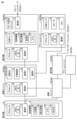
- FIG. 4 is a block diagram showing the configurations of the outdoor unit 10, indoor unit 20, shutoff unit 30, and alarm unit 40.
- FIG. 4 shows the outdoor unit 10, indoor units 20a, 20b, shutoff units 30a, 30b, and alarm units 40a, 40b.
- the indoor units 20a, 20b have a common configuration
- the shutoff units 30a, 30b have a common configuration
- the alarm units 40a, 40b have a common configuration.
- FIG. 4 shows the details of the configurations of the indoor unit 20a, shutoff unit 30a, and alarm unit 40a, while omitting the details of the configurations of the indoor unit 20b, shutoff unit 30b, and alarm unit 40b.
- the outdoor unit 10 includes a processor 11, a memory 12, a communication interface (I/F) 13, and an air conditioning mechanism 14.
- the air conditioning mechanism 14 includes a compressor 141, a heat exchanger 142, a fan 144, and a four-way valve 145.
- Processor 11 is typically configured with a CPU (Central Processing Unit) or an MPU (Multi-Processing Unit). Processor 11 is an example of a computing device.
- CPU Central Processing Unit
- MPU Multi-Processing Unit
- Memory 12 includes an area in which programs executed by processor 11 are stored, an area in which processor 11 temporarily stores program code, work memory, etc., and an area in which an ID for other devices such as shutoff unit 30 to identify outdoor unit 10 is stored.
- Memory 12 includes volatile memory such as DRAM (dynamic random access memory) and SRAM (static random access memory), ROM (read only memory), and non-volatile memory such as flash memory.
- Memory 12 may be an SSD (solid state drive) or HDD (hard disk drive), etc.
- the processor 11 has a communication function.
- the processor 11 allows the communication destination to identify the source of the communication by transmitting data including the ID stored in the memory 12 to the communication destination.
- the processor 11 communicates with the cutoff unit 30 (30a, 30b) via the communication interface (I/F) 13. Furthermore, the processor 11 communicates with the indoor unit 20 (20a, 20b) via the communication interface 13 and the cutoff unit 30.
- the processor 11 also communicates with the remote controller 60 located in the manager's room via the communication interface 13, the cutoff unit 30a, the cutoff unit 30b, and the indoor unit 20b.
- the processor 11, memory 12, and communication interface 13 constitute a control device provided in the outdoor unit 10.
- the control device is also an example of a processing circuit.
- the processor 11 controls various devices according to a program. This control is not limited to processing by software, and can also be processed by dedicated hardware (electronic circuitry).
- the indoor units 20 (20a, 20b) include a processor 21, a memory 22, a refrigerant sensor 23, an air conditioning mechanism 24, a sensor setting switch 25, and communication interfaces (I/F) 26, 27.
- the air conditioning mechanism 24 includes a heat exchanger 242, an expansion valve 243, and a fan 244.
- the heat exchanger 242 is an example of a heat exchanger that exchanges heat with the heat source unit.
- the air conditioning mechanism 14 of the outdoor unit 10, the air conditioning mechanism 24 of the indoor unit 20, and the piping 120 ( Figure 1) form a refrigerant circulation path and a refrigerant circuit through which the refrigerant circulates.
- the memory 22 includes an area in which an ID is stored so that other devices, such as the shutoff unit 30, can identify the indoor unit 20.
- the detailed configurations of the processor 21 and the memory 22 are similar to those of the processor 11 and the memory 12 already described, and therefore will not be described again here.
- the refrigerant sensor 23 detects refrigerant leaks in the indoor unit 20.
- the sensor setting switch 25 is a switch for switching the sensor function of the refrigerant sensor 23 between on and off.
- the sensor setting switch 25 is operated, for example, by a worker performing maintenance on the indoor unit 20.
- the processor 21 acquires sensor information from the refrigerant sensor 23.
- the processor 21 has a communication function.
- the processor 21 allows the communication destination to identify the source of communication by transmitting data including the ID stored in the memory 22 to the communication destination.
- the processor 21 communicates with the blocking unit 30 via the communication interface 26.
- the processor 21 communicates with the remote controller 50 via the communication interface 27.
- the shutoff unit 30 (30a, 30b) includes a processor 31, a memory 32, a shutoff valve 34 (34a, 34b), a backup power supply 35, and communication interfaces (I/F) 33, 36, and 37.
- Memory 32 includes an area in which an ID is stored that allows other devices, such as outdoor unit 10, to identify shutoff unit 30.
- the detailed configurations of processor 31 and memory 32 are similar to those of processor 11 and memory 12 already described, and therefore will not be described again here.
- the processor 31 has a communication function.
- the processor 31 transmits data including the ID stored in the memory 32 to the communication destination, thereby allowing the communication destination to identify the communication source.
- the processor 31 communicates with the outdoor unit 10 through the communication interface 33.
- the processor 31 communicates with the indoor unit 20 through the communication interface 36.
- the processor 31 communicates with the alarm unit 40 through the communication interface 37.
- the processor 31 closes the shutoff valves 34a and 34b. This closes the pipes 121a and 121b.
- the shutoff unit 30 switches the power supply source from the main power source to the backup power source 35.
- the backup power source 35 is composed of, for example, a secondary battery.
- the processor 31 operates using power supplied from the backup power source 35 and closes the shutoff valves 34a and 34b. This stops the supply of refrigerant to the indoor unit 20 during the power outage.
- the alarm unit 40 includes a processor 41, a memory 42, a refrigerant sensor 43, a speaker 44, an LED 45, and a communication interface (I/F) 47.
- the memory 42 includes an area in which an ID is stored that allows other devices, such as the cutoff unit 30, to identify the alarm unit 40.
- the detailed configurations of the processor 41 and memory 42 are similar to those of the processor 11 and memory 12 already described, and therefore will not be described again here.
- the refrigerant sensor 43 detects refrigerant leaks.
- the refrigerant sensor 43 is an example of an indoor refrigerant sensor.
- the processor 41 acquires sensor information from the refrigerant sensor 43. If a refrigerant leak is detected, the processor 41 generates an alarm sound from the speaker 44 and turns on the LED 45.
- the processor 41 has a communication function.
- the processor 41 allows the communication destination to identify the source of the communication by transmitting data including the ID stored in the memory 42 to the communication destination.
- the processor 41 communicates with the blocking unit 30 through the communication interface 47.
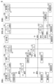
- FIG. 5 is a sequence diagram showing the process flow when a refrigerant leak is detected by the refrigerant sensor 23 of the indoor unit 20a.
- the alarm unit 40b and remote controller 50b located in room B are omitted from the illustration. The process flow will be explained below with reference to FIG. 5.
- the refrigerant sensor 23 detects a refrigerant leak in the indoor unit 20a (step S1).
- the indoor unit 20a notifies the remote controller 50a of the refrigerant leak (step S2), notifies the shutoff unit 30a of the refrigerant leak (step S4), and notifies the outdoor unit 10 of the refrigerant leak (step S8).
- the indoor unit 20a saves the history of the refrigerant leak in the memory 22 (see FIG. 4) (step S13) and stops air conditioning operation (step S14).
- the order in which steps S2, S4, S8, S13, and S14 are performed may be changed.
- the remote controller 50a issues an alarm based on the notification from the indoor unit 20a (step S3). More specifically, the remote controller 50a issues an alarm sound based on the notification of the refrigerant leak and displays alarm information. This allows the user in room A to become aware of the refrigerant leak. The remote controller 50a then saves the history of the refrigerant leak (step S18).
- the shutoff unit 30a closes the shutoff valves 34a and 34b based on the notification from the indoor unit 20a (step S5).
- the shutoff unit 30a closes the shutoff valves 34a and 34b, the pipes 121a and 121b are closed. This prevents the refrigerant leak from spreading.
- the shutoff unit 30a further notifies the alarm unit 40a of the refrigerant leak (step S6).
- the shutoff unit 30a then saves the refrigerant leak history in the memory 32 (see Figure 4) (step S15).
- steps S5, S6, and S15 may be changed.
- the shutoff unit 30a may notify the outdoor unit 10 of the refrigerant leak (step S8a).
- the alarm unit 40a issues an alarm based on the notification from the shutoff unit 30a (step S7). More specifically, the alarm unit 40a issues an alarm sound and turns on the LED 45 (see FIG. 4) based on the notification of the refrigerant leak. This allows the user in room A to become aware of the refrigerant leak.
- the outdoor unit 10 notifies the remote controller 60 located in the manager's room of the refrigerant leak based on the notification from the indoor unit 20a (step S9).
- the outdoor unit 10 further notifies the shutoff unit 30b and the indoor unit 20b located in room B of the refrigerant leak in room A based on the notification from the indoor unit 20a. More specifically, the outdoor unit 10 notifies the shutoff unit 30b and the indoor unit 20b of a "maintenance abnormality" message (steps S11 and S12).
- the order in which steps S9, S11, and S12 are performed may be changed.
- the outdoor unit 10 then saves the refrigerant leak history in the memory 12 (see FIG. 4) (step S19).
- the remote controller 60 issues an alarm based on the notification from the outdoor unit 10 (step S10). More specifically, the remote controller 60 issues an alarm sound based on the notification of a refrigerant leak and displays alarm information. This allows the manager to become aware of the refrigerant leak. The remote controller 60 then saves the history of the refrigerant leak (step S20).
- the shutoff unit 30b arranged in room B stores the refrigerant leak history information in memory 32 (see FIG. 4) based on the notification from the outdoor unit 10 (step S16).
- the indoor unit 20b arranged in room B stores the refrigerant leak history information in memory 22 (see FIG. 4) based on the notification from the outdoor unit 10 (step S17).
- the outdoor unit 10 It is desirable for the outdoor unit 10 to transmit the ID of the indoor unit 20a in which a refrigerant leak has been detected in each of steps S9, S11, and S12.
- the remote controller 60 may issue an alarm including the ID of the indoor unit 20 in which a refrigerant leak is occurring.
- each of the shutoff unit 30b and the indoor unit 20b may save a history including the ID of the indoor unit 20 in which a refrigerant leak is occurring.
- FIG. 6 is a sequence diagram showing the process flow when a refrigerant leak is detected by the refrigerant sensor 43 of the alarm unit 40a.
- the alarm unit 40b and remote controller 50b placed in room B are omitted. The process flow will be explained below with reference to FIG. 6.
- the refrigerant sensor 43 detects a refrigerant leak in room A (step S31).
- the alarm unit 40a issues an alarm (step S32). More specifically, the alarm unit 40a issues an alarm sound and turns on the LED 45 (see FIG. 4) based on the notification of the refrigerant leak. This allows the user in room A to become aware of the refrigerant leak.
- the alarm unit 40a further notifies the shutoff unit 30a of the refrigerant leak (step S33). The order in which steps S31 and S32 are executed may be changed.
- the shutoff unit 30a closes the shutoff valves 34a and 34b based on the notification from the alarm unit 40a (step S34).
- the shutoff unit 30a closes the shutoff valves 34a and 34b, the pipes 121a and 121b are closed. This prevents the refrigerant leak from spreading.
- the shutoff unit 30a further notifies the indoor unit 20a and the outdoor unit 10 of the refrigerant leak (steps S35 and S38).
- the shutoff unit 30a then stores the history of the refrigerant leak in the memory 32 (see FIG. 4) (step S45). The order in which steps S33, S34, S38, and S45 are performed may be changed.
- the indoor unit 20a notifies the remote controller 50a of the refrigerant leak based on the notification from the shutoff unit 30a (step S36). After that, the indoor unit 20a saves the refrigerant leak history in the memory 22 (see FIG. 4) (step S43) and stops the air conditioning operation (step S44).
- the order in which steps S36, S43, and S44 are executed may be changed.
- the remote controller 50a issues an alarm based on the notification from the indoor unit 20a (step S37). More specifically, the remote controller 50a issues an alarm sound based on the notification of the refrigerant leak and displays alarm information. This allows the user in room A to become aware of the refrigerant leak. The remote controller 50a then saves the history of the refrigerant leak (step S48).
- the outdoor unit 10 notifies the remote controller 60 located in the manager's room of the refrigerant leak based on the notification from the shutoff unit 30a (step S39).
- the outdoor unit 10 further notifies the shutoff unit 30b and the indoor unit 20b located in room B of the refrigerant leak in room A based on the notification from the shutoff unit 30a. More specifically, the outdoor unit 10 notifies the shutoff unit 30b and the indoor unit 20b of the refrigerant leak (steps S41 and S42) with a message that reads "Maintenance abnormality."
- the order in which steps S39, S41, and S42 are performed may be changed.
- the outdoor unit 10 then saves the history of the refrigerant leak in memory 12 (see FIG. 4) (step S49).
- the remote controller 60 issues an alarm based on the notification from the outdoor unit 10 (step S40). More specifically, the remote controller 60 issues an alarm sound based on the notification of a refrigerant leak and displays alarm information. This allows the manager to become aware of the refrigerant leak. The remote controller 60 then saves the history of the refrigerant leak (step S50).
- the shutoff unit 30b arranged in room B stores the refrigerant leak history information in memory 32 (see FIG. 4) based on the notification from the outdoor unit 10 (step S46).
- the indoor unit 20b arranged in room B stores the refrigerant leak history information in memory 22 (see FIG. 4) based on the notification from the outdoor unit 10 (step S47).
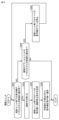
- FIG. 7 is a flowchart for explaining the process in which the shutoff unit 30 closes the shutoff valves 34 (34a, 34b) in the event of a power outage. The process executed by the shutoff unit 30 will be explained below based on the flowchart.
- step S101 When a power outage occurs (step S101), the shutoff unit 30 detects the power outage (step S102). Next, the shutoff unit 30 starts supplying power from the backup power supply 35 before the power supplied from the main power supply falls below a threshold (step S103). Next, the shutoff unit 30 closes the shutoff valve 34 using the power supplied from the backup power supply 35 (step S104).
- FIG. 8 is a flowchart for explaining the process in which the indoor unit 20 disables and enables the function of the refrigerant sensor 23 in response to the operation of the sensor setting switch 25. The process executed by the indoor unit 20 will be explained below based on the flowchart.
- the indoor unit 20 determines whether or not an operation to turn off the sensor function of the refrigerant sensor 23 has been detected (step S201). If the indoor unit 20 detects an operation to turn off the sensor function of the refrigerant sensor 23, it disables the sensor function of the refrigerant sensor 23 (step S202).
- the indoor unit 20 determines whether or not it has detected an operation to turn on the sensor function of the refrigerant sensor 23 (step S203). If the indoor unit 20 detects an operation to turn on the sensor function of the refrigerant sensor 23, it enables the sensor function of the refrigerant sensor 23 (step S204). If the indoor unit 20 does not detect an operation to turn on the sensor function of the refrigerant sensor 23, it ends the processing based on this flowchart.
- the refrigerant sensor 23 of the indoor unit 20 is enabled or disabled. If sufficient safety measures against refrigerant leakage have been implemented according to the air conditioning environment of the room, the designer may turn off the function of the refrigerant sensor 23 of the indoor unit 20. For example, the function of the refrigerant sensor 23 may be turned off in each of the cases where multiple alarm units 40 are placed in the room and where a ventilation device with high ventilation capacity is placed in the room.
- the blocking unit 30 is disposed as a separate device from the indoor unit 20.
- the blocking unit 30 may also be built into the indoor unit 20.
- the blocking unit 30a may be built into the indoor unit 20a
- the blocking unit 30b may be built into the indoor unit 20b.
- This modification discloses a configuration in which the blocking unit 30 is built into the indoor unit 20 in the air conditioning system 100 that includes the indoor unit 20 and the blocking unit 30.
- Fig. 9 is a diagram showing the configuration of an air conditioning system 100A according to the second embodiment.
- Fig. 10 is a flowchart for explaining the process executed by the blocking unit 30 when a refrigerant leak occurs.
- Embodiment 2 differs from embodiment 1 in the number of indoor units 20 subordinate to the shutoff unit 30a.
- embodiment 1 an example in which one indoor unit 20 is connected subordinate to the shutoff unit 30a is described.
- embodiment 2 an example in which two indoor units 20a, 20c are connected in parallel subordinate to the shutoff unit 30a is described.
- Embodiment 2 has the same configuration as embodiment 1, except for the number of indoor units 20 subordinate to the shutoff unit 30a.
- indoor units 20a and 20c are connected in parallel to pipe 121. Therefore, refrigerant flows between outdoor unit 10 and indoor unit 20a through pipe 121, and refrigerant flows between outdoor unit 10 and indoor unit 20c through pipe 121. As shown in FIG. 9, indoor units 20a and 20c are placed in room A, for example. Indoor unit 20c has a common configuration with indoor units 20a and 20b. Outdoor unit 10, shutoff unit 30a, shutoff unit 30b, indoor unit 20a, indoor unit 20b, and indoor unit 20c communicate through communication path L1.
- remote controller 50 (50c) is communicatively connected to indoor unit 20c.
- Two alarm units 40 (40a, 40c) are placed in room A.
- the shutoff unit 30a and alarm units 40a, 40c communicate with each other via communication path L2.
- the alarm units 40a and 40b may be placed in any location considered optimal for detecting refrigerant leaks.
- the alarm unit 40a may be placed near the indoor unit 20a
- the alarm unit 40b may be placed near the indoor unit 20b.
- a third alarm unit 40 may be placed in room A.
- the indoor unit 20a when a refrigerant leak is detected by the refrigerant sensor 23, the indoor unit 20a notifies the shutoff unit 30a of the refrigerant leak. Similarly, when a refrigerant leak is detected by the refrigerant sensor 23, the indoor unit 20c notifies the shutoff unit 30a of the refrigerant leak. When a refrigerant leak is notified from either the indoor unit 20a or the indoor unit 20c, the shutoff unit 30a closes the pipe 121 with the shutoff valve 34 and stops the air conditioning operation of the indoor unit 20a and the indoor unit 20c.
- the air conditioning system 100A executes the same processes as those shown in Figs. 5 to 8, which have been described as the process contents according to the first embodiment.
- the shutoff unit 30a when the shutoff unit 30a is notified of a refrigerant leak from one or both of the indoor units 20a, 20c, it notifies both the alarm units 40a, 40c of the refrigerant leak.
- the alarm units 40a, 40c issue an alarm based on the notification from the shutoff unit 30a.
- the outdoor unit 10 When the outdoor unit 10 is notified of a refrigerant leak from the indoor unit 20b in room B, it notifies the indoor units 20a and 20c in room A of a maintenance abnormality. That is, in the second embodiment, the process of step S12 in FIG. 5 is executed for the indoor units 20a and 20c.
- the outdoor unit 10 When the outdoor unit 10 is notified of a refrigerant leak from the shutoff unit 30b in room B, it notifies the indoor units 20a and 20c in room A of a maintenance abnormality. That is, in embodiment 2, the process of step S42 in FIG. 6 is executed for the indoor units 20a and 20c.
- shutoff unit 30 When a refrigerant leak occurs will be described.
- the process will be described using the shutoff unit 30a shown in FIG. 9 as a representative example of the shutoff unit 30.
- the shutoff unit 30a determines whether or not a refrigerant leak has been notified from either of the indoor units 20a, 20c subordinate to the shutoff unit 30a (step S301). If the indoor units 20a, 20c detect a refrigerant leak, they notify the shutoff unit 30a of the refrigerant leak together with the ID. Based on this notification, the shutoff unit 30a identifies the indoor unit 20 in which the refrigerant leak is occurring.
- shutoff unit 30a receives a notification of a refrigerant leak from either of the indoor units 20a and 20c subordinate to the shutoff unit 30a, the shutoff unit 30a closes the shutoff valve 34 (step S302). This stops the supply of refrigerant to the indoor units 20a and 20c. As a result, the refrigerant leak in room A is prevented from expanding.
- the shutoff unit 30a transmits an operation stop command to all indoor units 20a, 20c under the control of the shutoff unit 30a (step S303). This stops the air conditioning operation of the indoor units 20a, 20c.
- the shutoff unit 30a notifies the outdoor unit 10 of the indoor unit 20 in which a refrigerant leak has been detected (step S304). If a refrigerant leak has occurred in, for example, the indoor unit 20a out of the indoor units 20a, 20c, the shutoff unit 30a notifies the outdoor unit 10 of the ID of the indoor unit 20a. This allows the outdoor unit 10 to identify the indoor unit 20 in which a refrigerant leak is occurring.
- the outdoor unit 10 that has identified the indoor unit 20 in which a refrigerant leak is occurring executes steps S39, S41, and S42 in FIG. 6.
- the remote controller 60 located in the manager's room issues an alarm
- the shutoff unit 30b and the indoor unit 20b located in room B store the history of the refrigerant leak.
- step S301 judges whether or not there has been a refrigerant leak notification from any of the multiple alarm units 40a, 40b (step S305). If the shutoff unit 30a judges that there has been no refrigerant leak notification from any of the multiple alarm units 40a, 40b, it ends the processing based on this flowchart.
- shutoff unit 30a determines that a refrigerant leak has been notified from one of the alarm units 40a, 40b, it stops driving the fans 244 (see Figure 4) of all indoor units 20a, 20c under the control of the shutoff unit 30a (step S306).
- step S306 is executed to identify the indoor unit 20 in which a refrigerant leak is occurring.
- a refrigerant leak is not notified from the indoor unit 20a or indoor unit 20c (NO in step S301) but a refrigerant leak is notified from one of the multiple alarm units 40a, 40b, this means that a refrigerant leak occurring in the indoor unit 20a or indoor unit 20c has not been detected.
- a possible reason that a refrigerant leak is not detected in the indoor unit 20a or indoor unit 20c is that the concentration of the refrigerant leaking from the indoor unit 20 is quickly diluted due to the fast air flow in room A. If the concentration of the refrigerant leaking from the indoor unit 20 is quickly diluted, the refrigerant leak may not be detected depending on the detection accuracy of the refrigerant sensor 23.
- the shutoff unit 30a therefore temporarily stops or slows the air flow in room A by stopping the operation of the fans 244 in all indoor units 20a, 20c. This makes it easier for the leaked refrigerant to remain in the indoor unit 20 where the refrigerant leak is occurring. In other words, by executing the process of step S306, the shutoff unit 30a creates a situation in which it is easier for the refrigerant sensor 23 to detect a refrigerant leak.
- step S306 the shutoff unit 30a creates a situation in which the refrigerant sensor 23 can easily detect a refrigerant leak, and then returns to step S301.
- the shutoff unit 30a determines whether or not a refrigerant leak has been notified from either of the indoor units 20a, 20b subordinate to the shutoff unit 30a. Thereafter, the shutoff unit 30a repeats the processes of steps S301, S305, and S306 until a refrigerant leak has been notified from either of the indoor units 20a, 20b subordinate to the shutoff unit 30a.
- the shutoff unit 30a can identify the indoor unit 20 in which the refrigerant leak is occurring. If the shutoff unit 30a identifies the indoor unit 20 in which the refrigerant leak is occurring, the shutoff unit 30a determines YES in step S301. Thereafter, the shutoff unit 30a executes the processes in steps S302 to S304 already described.
- the second embodiment has been described above using Figures 9 and 10.
- the air conditioning system 100A of the second embodiment similar to the air conditioning system 100 of the first embodiment, it is possible to strengthen safety measures against refrigerant leakage compared to the conventional art.
- FIG. 11 is a diagram showing the configuration of an air conditioning system 100B according to the third embodiment.
- Embodiment 3 differs from embodiment 2 in that a configuration for making room C a space to be air-conditioned is added.
- an indoor unit 20d is disposed as the indoor unit 20 subordinate to the shutoff unit 30a.
- An alarm unit 40d and a remote controller 50d are also disposed in room C.
- Embodiment 3 has the same configuration as embodiment 2, except for the addition of a configuration for making room C a space to be air-conditioned.
- three indoor units 20a, 20c, and 20d are connected in parallel under the shutoff unit 30a. That is, in the third embodiment, the indoor units 20a, 20c, and 20c are connected in parallel to the pipe 121. Therefore, the refrigerant flows between the outdoor unit 10 and the indoor unit 20a through the pipe 121, the refrigerant flows between the outdoor unit 10 and the indoor unit 20b through the pipe 121, and the refrigerant flows between the outdoor unit 10 and the indoor unit 20c through the pipe 121.
- the indoor unit 20d is capable of communicating with the outdoor unit 10 and the shutoff unit 30a through communication path L1.
- the indoor unit 20d is equipped with a refrigerant sensor 23, just like the indoor unit 20a. If a refrigerant leak is detected by the refrigerant sensor 23, the indoor unit 20d notifies the shutoff unit 30a of the refrigerant leak.
- a remote controller 50d is communicatively connected to the indoor unit 20d, just like the indoor unit 20a.
- An alarm unit 40d is placed in room C.
- the shutoff unit 30a and the alarm unit 40d communicate with each other through communication path L2.
- shutoff unit 30a If the shutoff unit 30a is notified of a refrigerant leak from any of the indoor units 20a, 20c, or 20d, it closes the shutoff valve 34. This blocks the flow of refrigerant to the indoor units 20a, 20c, or 20d. As a result, the refrigerant leak occurring in either room A or C is prevented from expanding.
- the process executed by the shutoff unit 30a in the third embodiment is the same as that shown in the flowchart of FIG. 10, which has already been described. Therefore, the description will not be repeated here.
- the alarm unit 40d notifies the shutoff unit 30a of a refrigerant leak when the indoor unit 20d has not notified the shutoff unit 30a of a refrigerant leak
- the shutoff unit 30a does not need to execute the process of stopping the fan drive (step S306). This is because in this case, it is presumed that the refrigerant leak has occurred in the indoor unit 20d.
- the outdoor unit 10 receives a notification of the refrigerant leak from the shutoff units 30a, 30b or the indoor units 20a to 20d. In this case, the outdoor unit 10 notifies the remote controller 60 located in the manager's room of the refrigerant leak. Based on the notification of the refrigerant leak, the remote controller 60 issues an alarm of the refrigerant leak.
- the air conditioning system 100B similar to the air conditioning system 100 according to the first embodiment, it is possible to strengthen safety measures against refrigerant leakage compared to the conventional art.
- one indoor unit 20d is placed in room C.
- multiple indoor units 20 may be placed in room C.
- the multiple indoor units 20 placed in room C may be added to the control of the shutoff unit 30a.
- the shutoff unit 30 may be designed so that a maximum of about eight indoor units 20 can be placed under the control of the shutoff unit 30.
- FIG. 12 is a diagram showing the configuration of an air conditioning system 100C according to the fourth embodiment.
- Embodiment 4 differs from embodiment 3 in that a configuration for making room D a space to be air-conditioned is added.
- the spatial size of room D is significantly larger than the spatial sizes of rooms A to C.
- Room D is, for example, a large hall.
- an indoor unit 20e and a remote controller 50e that is communicatively connected to the indoor unit 20e are arranged.
- the indoor unit 20e communicates with the outdoor unit 10 and the shutoff units 30a and 30b via communication path L1.
- No alarm unit 40 is installed in room D.
- the indoor unit 20e is equipped with a refrigerant sensor 23. If the indoor unit 20e detects a refrigerant leak by the refrigerant sensor 23, it notifies the outdoor unit 10 and the remote controller 50e of the refrigerant leak. The remote controller 50e issues an alarm of the refrigerant leak based on the notification from the indoor unit 20e.
- the outdoor unit 10 performs processing such as notifying the remote controller 60 in the manager's room of the refrigerant leak based on the notification from the indoor unit 20e. The details of the processing by the outdoor unit 10 at this time are the same as the processing contents already explained using FIG. 5.
- the indoor unit 20e and the remote controller 60 located in the manager's room communicate with each other through a communication path L3 established between the indoor unit 20e and the remote controller 60. If a refrigerant leak occurs in any of the rooms A to D, the remote controller 60 issues an alarm about the refrigerant leak.
- the indoor unit 20e is directly connected to the outdoor unit 10 by the piping 120, without going through the shutoff unit 30. Therefore, if a refrigerant leak is detected in room D, the piping 120 between the outdoor unit 10 and the indoor unit 20e will not be closed by the shutoff unit 30.
- room D is not provided with a mechanism for shutting off piping 120 or an alarm unit 40 as a safety measure against refrigerant leaks.
- embodiment 4 by taking into account the size of room D, it is possible to reduce costs while strengthening safety measures against refrigerant leaks compared to conventional methods.
- indoor unit 20e may be subordinate to shutoff unit 30b or shutoff unit 30a, and an alarm unit 40 may be placed in room D.
- the outdoor unit 10 may detect a refrigerant leak occurring in room D by monitoring the pressure of the refrigerant supplied to the indoor unit 20e. If the outdoor unit 10 detects a refrigerant leak occurring in room D using such a method, it may instruct the indoor unit 20e to close the valve of the refrigerant pipe located inside the indoor unit 20e.
- FIG. 13 is a diagram showing the configuration of an air conditioning system 100D according to the fifth embodiment.
- Embodiment 5 differs from embodiment 4 in that a branch controller 90 is provided between the outdoor unit 10 and the shutoff units 30a, 30b. Furthermore, in embodiment 5, the configuration of the equipment placed in rooms A to C is different from that in embodiment 4. It can be said that embodiment 5 is one variation of embodiment 4.
- the diversion controller 90 is connected to the outdoor unit 10 by a pair of pipes 123.
- the diversion controller 90 includes a diversion mechanism 91 for divert- ing the refrigerant.
- the diversion mechanism 91 is composed of an expansion valve, a heat exchanger, and a refrigerant branch path.
- the diversion controller 90 is connected to the shutoff unit 30a by a pair of pipes 124.
- the diversion controller 90 is connected to the shutoff unit 30b by a pair of pipes 125.
- the diversion controller 90 is connected to the indoor unit 20e by a pair of pipes 126.
- indoor unit 20a under shutoff unit 30a is placed in room A
- indoor unit 20b under shutoff unit 30b is placed in room B
- indoor units 20c and 20d under shutoff unit 30b are placed in room C
- Indoor unit 20e is placed in room D, as in embodiment 4.
- the diversion controller 90 controls the air conditioning mode of the indoor unit 20a under the shutoff unit 30a, the air conditioning mode of the indoor units 20b to 20d under the shutoff unit 30b, and the air conditioning mode of the indoor unit 20e by controlling the flow of refrigerant in the pipes 124 to 126.
- the diversion controller 90 can operate the indoor unit 20a under the shutoff unit 30a in cooling mode, while operating the indoor unit 20e and the indoor units 20b to 20d under the shutoff unit 30b in heating mode.
- the air conditioning system 100D according to the fifth embodiment similar to the air conditioning system 100 according to the first embodiment, it is possible to strengthen safety measures against refrigerant leakage compared to the conventional art.
- the branch controller 90 introduced as the fifth embodiment may be applied to any of the first to fourth embodiments.
- shutoff unit 30 is disposed as a separate device from the diversion controller 90.
- the shutoff unit 30 may be built into the diversion controller 90.
- the shutoff units 30a and 30b may be built into the diversion controller 90.
- This modification discloses a configuration in which the shutoff unit 30 is built into the diversion controller 90 in an air conditioning system 100 that includes an indoor unit 20, a shutoff unit 30, and a diversion controller 90.
- the refrigerant sensor 23 connected to the indoor unit 20 may be provided inside the indoor unit 20 or outside the indoor unit 20.
- the present disclosure relates to an air conditioning system (100, 100A-100D) including a heat source unit (10), a first indoor unit (20a) having a first heat exchanger (242) that exchanges heat with the heat source unit via a refrigerant and that blows out conditioned air to a first air conditioned space (A), a first shutoff unit (30a) having a first shutoff valve (34), an alarm device (50a) arranged in the first air conditioned space, a first alarm unit (40a) arranged in the first air conditioned space (A), a first refrigerant sensor (23) provided in the first indoor unit and detecting a refrigerant leak, and a second refrigerant sensor (24) connected to the first alarm unit and detecting the refrigerant leak.
- a heat source unit (10) including a first indoor unit (20a) having a first heat exchanger (242) that exchanges heat with the heat source unit via a refrigerant and that blows out conditioned air to a first air conditioned space (A),
- the heat source unit and the first indoor unit are connected by a first piping (121) through which a refrigerant flows, and the alarm device issues an alarm when a refrigerant leak is detected by the first refrigerant sensor (step S3), the first alarm unit issues an alarm when a refrigerant leak is detected by the indoor refrigerant sensor (step S7), and the first shutoff unit closes the first piping with the first shutoff valve when a refrigerant leak is detected by the first refrigerant sensor and when a refrigerant leak is detected by the indoor refrigerant sensor (steps S5, S34).
- step S2 In the air conditioning system (100, 100A-100D) described in 1, when a refrigerant leak is detected by the first refrigerant sensor, the first indoor unit notifies the first shutoff unit and the alarm device of the refrigerant leak (steps S2, S4), the first shutoff unit closes the first piping with the first shutoff valve based on the notification from the first indoor unit (step S5) and notifies the first alarm unit of the refrigerant leak (step S6), the alarm device issues an alarm based on the notification from the first indoor unit (step S3), and the first alarm unit issues an alarm based on the notification from the first shutoff unit (step S7).
- the first alarm unit notifies the first shutoff unit of the refrigerant leak and issues an alarm (steps S32, S33), the first shutoff unit closes the first piping with the first shutoff valve based on the notification from the first alarm unit and notifies the first indoor unit of the refrigerant leak (steps S34, S35), the first indoor unit notifies the alarm device of the refrigerant leak based on the notification from the first shutoff unit (step S36), and the alarm device issues an alarm based on the notification from the first indoor unit (step S37).
- the first indoor unit receives an instruction to disable the sensor function of the first refrigerant sensor (step S202).
- the air conditioning system (100, 100A-100D) described in any one of paragraphs 1 to 4 further includes a first communication path (L1) for establishing communication between the heat source unit, the first shutoff unit, and the first indoor unit, and a second communication path (L2) for establishing communication between the first shutoff unit and the first alarm unit.
- the air conditioning system (100, 100A to 100D) described in 5 further includes a third communication path (L3) for establishing communication between the first indoor unit and the alarm device.
- the air conditioning system (100, 100A-100D) described in any one of 1 to 6 further includes a management alarm device (60) arranged in a manager space different from the first target space, and the first indoor unit notifies the heat source unit of the refrigerant leak when the first refrigerant sensor detects a refrigerant leak (step S8), the first shutoff unit notifies the heat source unit of the refrigerant leak when the indoor refrigerant sensor detects a refrigerant leak (step S38), the heat source unit notifies the management alarm device of the refrigerant leak based on the notifications from the first indoor unit and the first shutoff unit (steps S9, S39), and the management alarm device issues an alarm based on the notification from the heat source unit (steps S10, S40).
- a management alarm device 60
- the heat source unit is further provided with a second refrigerant sensor (23) for detecting a medium leak, and the heat source unit and the second indoor unit are connected by a second pipe (122) through which the refrigerant flows.
- the second shutoff unit is configured to close the second pipe with a second shutoff valve when a refrigerant leak is detected by the second refrigerant sensor. Based on the notification from the first shutoff unit, the heat source unit notifies each of the second indoor unit and the second shutoff unit of the refrigerant leak in the first air-conditioned space (steps S41 and S42).
- the air conditioning system (100A-100D) described in any one of paragraphs 1 to 8 further includes a third indoor unit (20c) having a heat exchanger (242) for exchanging heat with the heat source unit and blowing conditioned air into the first air-conditioned space, the first indoor unit and the third indoor unit are connected in parallel to the first piping, the third indoor unit has a third refrigerant sensor (23) for detecting a refrigerant leak, the third indoor unit notifies the first shutoff unit of the refrigerant leak when the third refrigerant sensor detects a refrigerant leak, and the first shutoff unit closes the first piping with the first shutoff valve when a refrigerant leak is notified from either the first indoor unit or the third indoor unit (step S302).
- a third indoor unit (20c) having a heat exchanger (242) for exchanging heat with the heat source unit and blowing conditioned air into the first air-conditioned space
- the first indoor unit and the third indoor unit are connected in parallel to the first piping
- the first indoor unit and the third indoor unit each have a fan (244) for blowing air, and the first shutoff unit stops driving the fans in the first indoor unit and the third indoor unit (Step S306) when a refrigerant leak is detected by the indoor refrigerant sensor and no refrigerant leak is notified from either the first indoor unit or the third indoor unit (Step S305).
- the air conditioning system (100B) described in any one of Items 9 to 11 further includes a fourth indoor unit (20d) that has a heat exchanger (242) that exchanges heat with the heat source unit and blows conditioned air into a third air-conditioned space (Room C), the first indoor unit, the second indoor unit, and the fourth indoor unit are connected in parallel to the first piping, the fourth indoor unit has a fourth refrigerant sensor (23) that detects a refrigerant leak, and when the fourth indoor unit detects a refrigerant leak by the fourth refrigerant sensor, the fourth indoor unit notifies the first shutoff unit of the refrigerant leak, and the first shutoff unit closes the first piping with the first shutoff valve based on the notification from the fourth indoor unit.
- a fourth indoor unit (20d) that has a heat exchanger (242) that exchanges heat with the heat source unit and blows conditioned air into a third air-conditioned space (Room C), the first indoor unit, the second indoor unit, and the fourth indoor unit are connected in
- the first shutoff unit has a backup power supply (35), and when a power outage is detected, the first shutoff unit switches the power supply source from the main power supply to the backup power supply (steps S101 to S103).
- the air conditioning system (100C) described in items 12 or 13 further includes a fifth indoor unit (20e) having a heat exchanger for exchanging heat with the heat source unit and blowing conditioned air into a fourth air-conditioned space (room D), the fourth air-conditioned space being larger in spatial size than any of the first air-conditioned space, the second air-conditioned space, and the third air-conditioned space, the fifth indoor unit being connected to the heat source unit by a third pipe different from the first pipe and the second pipe, and no alarm unit corresponding to the first alarm unit or the second alarm unit is disposed in the fourth air-conditioned space.
- a fifth indoor unit (20e) having a heat exchanger for exchanging heat with the heat source unit and blowing conditioned air into a fourth air-conditioned space (room D), the fourth air-conditioned space being larger in spatial size than any of the first air-conditioned space, the second air-conditioned space, and the third air-conditioned space, the fifth indoor unit being connected to the heat source unit by a third pipe different from the first pipe and the second pipe, and no alarm
Landscapes
- Engineering & Computer Science (AREA)
- Chemical & Material Sciences (AREA)
- Combustion & Propulsion (AREA)
- Mechanical Engineering (AREA)
- General Engineering & Computer Science (AREA)
- Human Computer Interaction (AREA)
- Air Conditioning Control Device (AREA)
Priority Applications (3)
| Application Number | Priority Date | Filing Date | Title |
|---|---|---|---|
| DE112023006538.1T DE112023006538T5 (de) | 2023-06-21 | 2023-06-21 | Klimaanlagensystem |
| PCT/JP2023/023003 WO2024261924A1 (ja) | 2023-06-21 | 2023-06-21 | 空気調和システム |
| JP2025527314A JPWO2024261924A1 (https=) | 2023-06-21 | 2023-06-21 |
Applications Claiming Priority (1)
| Application Number | Priority Date | Filing Date | Title |
|---|---|---|---|
| PCT/JP2023/023003 WO2024261924A1 (ja) | 2023-06-21 | 2023-06-21 | 空気調和システム |
Publications (1)
| Publication Number | Publication Date |
|---|---|
| WO2024261924A1 true WO2024261924A1 (ja) | 2024-12-26 |
Family
ID=93934966
Family Applications (1)
| Application Number | Title | Priority Date | Filing Date |
|---|---|---|---|
| PCT/JP2023/023003 Ceased WO2024261924A1 (ja) | 2023-06-21 | 2023-06-21 | 空気調和システム |
Country Status (3)
| Country | Link |
|---|---|
| JP (1) | JPWO2024261924A1 (https=) |
| DE (1) | DE112023006538T5 (https=) |
| WO (1) | WO2024261924A1 (https=) |
Citations (5)
| Publication number | Priority date | Publication date | Assignee | Title |
|---|---|---|---|---|
| JPH0942808A (ja) * | 1995-07-31 | 1997-02-14 | Sanyo Electric Co Ltd | 低温庫 |
| WO2017002213A1 (ja) * | 2015-06-30 | 2017-01-05 | 三菱電機株式会社 | 冷媒漏洩検知装置 |
| JP2017053509A (ja) * | 2015-09-08 | 2017-03-16 | ジョンソンコントロールズ ヒタチ エア コンディショニング テクノロジー(ホンコン)リミテッド | 空気調和システムおよび空気調和システムの警告報知方法 |
| JP2020134005A (ja) * | 2019-02-19 | 2020-08-31 | パナソニックIpマネジメント株式会社 | 空気調和装置 |
| WO2021199163A1 (ja) * | 2020-03-30 | 2021-10-07 | 三菱電機株式会社 | 空気調和システム |
Family Cites Families (1)
| Publication number | Priority date | Publication date | Assignee | Title |
|---|---|---|---|---|
| JP7152648B2 (ja) | 2016-10-28 | 2022-10-13 | ダイキン工業株式会社 | 空気調和装置 |
-
2023
- 2023-06-21 DE DE112023006538.1T patent/DE112023006538T5/de active Pending
- 2023-06-21 JP JP2025527314A patent/JPWO2024261924A1/ja active Pending
- 2023-06-21 WO PCT/JP2023/023003 patent/WO2024261924A1/ja not_active Ceased
Patent Citations (5)
| Publication number | Priority date | Publication date | Assignee | Title |
|---|---|---|---|---|
| JPH0942808A (ja) * | 1995-07-31 | 1997-02-14 | Sanyo Electric Co Ltd | 低温庫 |
| WO2017002213A1 (ja) * | 2015-06-30 | 2017-01-05 | 三菱電機株式会社 | 冷媒漏洩検知装置 |
| JP2017053509A (ja) * | 2015-09-08 | 2017-03-16 | ジョンソンコントロールズ ヒタチ エア コンディショニング テクノロジー(ホンコン)リミテッド | 空気調和システムおよび空気調和システムの警告報知方法 |
| JP2020134005A (ja) * | 2019-02-19 | 2020-08-31 | パナソニックIpマネジメント株式会社 | 空気調和装置 |
| WO2021199163A1 (ja) * | 2020-03-30 | 2021-10-07 | 三菱電機株式会社 | 空気調和システム |
Also Published As
| Publication number | Publication date |
|---|---|
| DE112023006538T5 (de) | 2026-04-09 |
| JPWO2024261924A1 (https=) | 2024-12-26 |
Similar Documents
| Publication | Publication Date | Title |
|---|---|---|
| US10488072B2 (en) | Air conditioning system with leak protection control | |
| JP6899896B2 (ja) | 空調システム | |
| JP5405161B2 (ja) | 空気調和装置およびエネルギー機器 | |
| US10808960B2 (en) | Refrigeration cycle apparatus | |
| CN108307648B (zh) | 空调装置 | |
| JP2012013339A (ja) | 空気調和機 | |
| CN105864964A (zh) | 空调器的故障处理方法、故障处理装置和空调器 | |
| JP6572622B2 (ja) | 空調換気システム | |
| AU2017413868B2 (en) | Air-conditioning system and refrigerant-amount setting method for the same | |
| JP6253853B1 (ja) | 冷凍サイクル装置 | |
| JPWO2021199163A5 (https=) | ||
| JP2016151395A (ja) | 空気調和装置 | |
| JP6558066B2 (ja) | 空調換気システム | |
| WO2024261924A1 (ja) | 空気調和システム | |
| JP2025078865A (ja) | 空気調和装置 | |
| JP2016211793A (ja) | 空調換気システム | |
| CN100516680C (zh) | 统一控制一拖多型空调系统及其控制方法 | |
| JP2019215153A (ja) | 空調換気システム | |
| WO2024261927A1 (ja) | 空気調和システム | |
| JP5450208B2 (ja) | 空気調和装置 | |
| WO2024261925A1 (ja) | 空気調和システム | |
| JP7566221B1 (ja) | 空気調和装置、及び制御方法 | |
| JP2021162232A (ja) | 空気調和装置 | |
| WO2024261926A1 (ja) | 空気調和装置 | |
| JP2007085686A (ja) | 空気調和システム及びその運転方法 |
Legal Events
| Date | Code | Title | Description |
|---|---|---|---|
| 121 | Ep: the epo has been informed by wipo that ep was designated in this application |
Ref document number: 23942360 Country of ref document: EP Kind code of ref document: A1 |
|
| ENP | Entry into the national phase |
Ref document number: 2025527314 Country of ref document: JP Kind code of ref document: A |
|
| WWE | Wipo information: entry into national phase |
Ref document number: 2025527314 Country of ref document: JP |
|
| WWE | Wipo information: entry into national phase |
Ref document number: 112023006538 Country of ref document: DE |