WO2024261861A1 - エレベーターの制御装置 - Google Patents
エレベーターの制御装置 Download PDFInfo
- Publication number
- WO2024261861A1 WO2024261861A1 PCT/JP2023/022761 JP2023022761W WO2024261861A1 WO 2024261861 A1 WO2024261861 A1 WO 2024261861A1 JP 2023022761 W JP2023022761 W JP 2023022761W WO 2024261861 A1 WO2024261861 A1 WO 2024261861A1
- Authority
- WO
- WIPO (PCT)
- Prior art keywords
- position information
- car
- linear scale
- elevator
- learning
- Prior art date
- Legal status (The legal status is an assumption and is not a legal conclusion. Google has not performed a legal analysis and makes no representation as to the accuracy of the status listed.)
- Ceased
Links
Images


Classifications
-
- B—PERFORMING OPERATIONS; TRANSPORTING
- B66—HOISTING; LIFTING; HAULING
- B66B—ELEVATORS; ESCALATORS OR MOVING WALKWAYS
- B66B3/00—Applications of devices for indicating or signalling operating conditions of elevators
- B66B3/02—Position or depth indicators
-
- B—PERFORMING OPERATIONS; TRANSPORTING
- B66—HOISTING; LIFTING; HAULING
- B66B—ELEVATORS; ESCALATORS OR MOVING WALKWAYS
- B66B7/00—Other common features of elevators
Definitions
- This disclosure relates to elevator control devices.
- Patent Document 1 discloses an example of an elevator control device.
- the elevator is equipped with a just-level sensor that detects when the car has landed at each floor landing.
- the worker performing the adjustment manually drives the car to the top floor and the bottom floor, and then has the car move back and forth within the elevator shaft.
- the linear scale When replacing a linear scale such as a magnetic tape in an elevator, the linear scale is cut to the required length for each property and installed.
- the detection value of the absolute position of the end point of the linear scale depends on the cutting position of the linear scale, so the offset will be different for each linear scale after cutting.
- the method sets the absolute positions of the top and bottom floors, which are the terminal floors, by manual operation. At this time, the task of setting the absolute positions by manual operation requires fine adjustments by the worker, and depending on the level of skill of the worker, work efficiency may decrease.
- This disclosure is directed to solving such problems.
- This disclosure provides an elevator control device that can improve the work efficiency of replacing linear scales.
- the elevator control device includes a linear scale provided along the travel path of a car traveling vertically within a hoistway and on which position information within the hoistway is provided along the longitudinal direction, a position detector provided in the car and detecting the absolute position of the car in the hoistway by reading the position information provided on the linear scale, a car control unit that controls the travel of the car based on the absolute position of the car detected by the position detector from the position information on the linear scale, and a first end detection unit that detects the car when it is at the end of the vertical direction of the hoistway.
- the learning unit pre-stores, as first position information, the position information read from the linear scale by the position detector when the first end detection unit detects the car before the linear scale is replaced, and acquires, as second position information, the position information read from the linear scale by the position detector when the first end detection unit detects the car after the linear scale is replaced, and learns the offset of the linear scale based on the difference between the first position information and the second position information.
- the elevator control device disclosed herein can improve the work efficiency of replacing linear scales.
- FIG. 1 is a configuration diagram of an elevator according to a first embodiment.
- 4 is a flowchart showing an example of a procedure for installing an elevator control device according to the first embodiment.
- 4 is a flowchart showing an example of a procedure for replacing a linear scale of an elevator control device according to embodiment 1.
- 2 is a hardware configuration diagram of a main part of a control device according to the first embodiment.
- FIG. FIG. 11 is a configuration diagram of an elevator according to a modified example of the first embodiment.
- FIG. 11 is a configuration diagram of an elevator according to a second embodiment.
- 13 is a flowchart showing an example of a procedure for installing an elevator control device according to embodiment 2.
- 13 is a flowchart showing an example of a procedure for replacing a linear scale of an elevator control device according to embodiment 2.
- FIG. 11 is a configuration diagram of an elevator according to a modified example of embodiment 2.
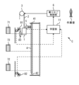
- FIG. 1 is a configuration diagram of an elevator according to the first embodiment.
- Elevators are applied to buildings with multiple floors.
- An elevator shaft is provided in the building.
- the shaft is a long space in the vertical direction that spans multiple floors.
- the elevator includes a car 1, a rope 2, and a hoist 3.
- the car 1 is a device in which passengers and the like board.
- the car 1 is arranged in the hoistway.
- the rope 2 is a device that supports the load of the car 1.
- the rope 2 is a long object such as a strand rope or a belt rope.
- the hoist 3 is a device that generates a driving force to run the car 1.
- the hoist 3 is arranged at the top or bottom of the hoistway. If the elevator machine room is provided above the hoistway, the hoist 3 may be arranged in the machine room.
- the rope 2 is wound around the hoist 3.
- the rope 2 is wound around a sheave of the hoist 3.
- one side of the rope 2 wound around a sheave is wound up by the driving force generated by the hoist 3, causing the car 1 supported by the rope 2 to travel up and down the elevator shaft.
- a control device C is applied to control the operation of the elevator.
- the control device C includes a linear scale 4 and a position detector 5.
- the linear scale 4 is arranged along the travel path of the car 1 in the elevator.
- the linear scale 4 is, for example, a long object in the shape of a tape, ribbon, belt, rope, or rod.
- the longitudinal direction of the linear scale 4 is oriented in the vertical direction, which is the travel direction of the car 1.
- the linear scale 4 is provided with position information within the elevator corresponding to the absolute vertical position of the car 1 in the elevator.
- the position information within the elevator is provided along the longitudinal direction of the linear scale 4 by, for example, electromagnetic characteristics, optical characteristics, mechanical shape or properties, or a geometric pattern of the surface.
- the linear scale 4 is provided in a hanging manner such that the upper end 41 is fixed and the lower end 42 is movable in the vertical direction.
- the upper end 41 is an example of a fixed end.
- the lower end 42 is an example of a movable end opposite the fixed end.
- the linear scale 4 has an expandable and contractible characteristic.
- the lower end 42 which is the movable end, may be held by an elastic body such as a spring so as to apply tension to the linear scale 4, or may be held by a slide bearing or the like.
- the linear scale 4 may be provided such that the lower end 42 is fixed and the upper end 41 is movable in the vertical direction.
- the position detector 5 is provided on the car 1.
- the position detector 5 is fixed to the car 1.
- the position detector 5 has a function for reading the position information attached to the linear scale 4.
- the position detector 5, which moves in the elevator shaft together with the car 1, reads the position information of the linear scale 4 to read the absolute position of the car 1 in the elevator shaft.
- the control device C includes a car control unit 6.
- the car control unit 6 is mounted on a control panel provided, for example, at the top or bottom of the elevator shaft, or in a machine room.
- the car control unit 6 is a part that has a function to control the running of the car 1.
- the car control unit 6 controls the running of the car 1 using a read value obtained by reading the position information attached to the linear scale 4 by the position detector 5.
- the car control unit 6 may apply the read value to a door-open running protection device and a terminal floor forced deceleration device provided in the elevator.
- stop floor 71 is the top floor.
- Stop floor 72 is the bottom floor.
- Stop floor 73 is an intermediate floor.
- the elevator may have multiple intermediate floors, including floors other than stop floor 73. The number and height of the elevator stop floors vary depending on the structure of the building, such as the height and number of floors.
- the control device C includes an end detection unit 81.
- the end detection unit 81 is provided as a stopping means in the upward direction near the stop floor 71, which is the top floor.
- the end detection unit 81 is provided at the end of the upper end 41 side, which is the fixed end of the linear scale 4, i.e., at the upper end of the elevator shaft.
- the end detection unit 81 is equipped with a function of detecting the car 1 by a contact or non-contact method when the car 1 is at the upper end of the elevator shaft.
- the end detection unit 81 detects the car 1, for example, by contacting a cam 83 provided on the car 1 when the car 1 travels through the installation location of the end detection unit 81.
- the end detection unit 81 may detect the car 1 by a sensor provided on the car 1 detecting a detection plate provided at the upper end of the elevator shaft in a non-contact manner.
- the end detection unit 81 is an example of a first end detection unit. That is, the first end detection unit may be a contact-type end detection unit 81 that detects the car 1 using a cam 83, or it may be an end detection unit 81 that detects a detection plate such as a door zone plate in a non-contact manner.
- the control device C includes a safety circuit 9.
- the safety circuit 9 is mounted, for example, on a control panel provided at the top or bottom of the elevator shaft, or in a machine room.
- the safety circuit 9 has a function of cutting off the power of the hoisting machine 3 that drives the car 1 and braking the hoisting machine 3 when the terminal detector 81 detects the car 1.
- the control device C includes an emergency electric driving unit 10.
- the emergency electric driving unit 10 is mounted, for example, on a control panel provided at the upper or lower part of the elevator shaft, or in a machine room.
- the emergency electric driving unit 10 has a function for disabling the control of the car 1 operation by the safety circuit 9 when the end detection unit 81 detects the car 1.
- the emergency electric driving unit 10 causes the car control unit 6 to control the running of the car 1 so that the car 1 runs at a low speed lower than the rated speed.
- the installation of the emergency electric driving unit 10 is required by elevator standards such as EN81-20, and the emergency electric driving unit 10 is provided at least in elevators installed in areas where compliance with the standards is required.
- the control device C includes a learning unit 11.
- the learning unit 11 is mounted, for example, on a control panel provided at the upper or lower part of the elevator shaft, or in a machine room.
- the learning unit 11 has a function for learning the offset of the position information of the linear scale 4.
- the learning unit 11 learns the offset, for example, when the linear scale 4 is replaced.
- the learning unit 11 learns the offset using information from the linear scale 4 before replacement.
- the learning unit 11 has multiple states including a normal operation state and a learning-enabled state.
- the normal operation state is the state during normal operation of the elevator. In the normal operation state, the learning unit 11 does not learn the offset.
- the car control unit 6 acquires the absolute position of the car 1 using the offset most recently learned by the learning unit 11, and controls the running of the car 1.
- the learning-enabled state is a state in which the offset can be learned.
- the learning unit 11 is set to the learning-enabled state, for example, immediately after the elevator is installed, immediately after the elevator returns from maintenance and inspection or degenerate operation, or immediately after the linear scale 4 is replaced.
- the learning unit 11 prestores, as the first position information, the position information read by the position detector 5 from the linear scale 4 when the end detection unit 81 detects the car 1.
- the first position information stored by the learning unit 11 is not limited to the value read immediately before replacing the linear scale 4.
- the first position information stored by the learning unit 11 may be the value read immediately after the previous replacement of the linear scale 4, or the value read during the previous maintenance inspection.
- the learning unit 11 reads and stores the first position information from the linear scale 4 before replacement.
- the car 1 When the learning unit 11 reads the first position information used to learn the offset, the car 1 continues to operate at a low speed lower than the rated speed without making an emergency stop. If the end detection unit 81 operates when the learning unit 11 reads the first position information, the car 1 stops running once. In addition, if the upper end 41 of the linear scale 4 is set as a movable end that can move in the vertical direction, it is necessary to learn the offset value on the lower end 42 side.
- the learning unit 11 After replacing the linear scale 4, the learning unit 11 stores, as second position information, the position information that the position detector 5 reads from the linear scale 4 when the end detection unit 81 detects the car 1.
- the learning unit 11 when the end detection unit 81 detects the car 1 while the emergency electric driving unit 10 is driving the car 1 at a low speed, the learning unit 11 reads and stores the second position information from the replaced linear scale 4.
- the second position information is acquired, for example, when the learning unit 11 is in a learning-enabled state.
- the learning unit 11 reads the first position information used to learn the offset, the car 1 continues to drive at a low speed lower than the rated speed without making an emergency stop. If the end detection unit 81 operates when the learning unit 11 reads the second position information, the car 1 stops running temporarily.
- the learning unit 11 learns the offset of the linear scale 4 based on the difference between the first position information and the second position information, for example, when the learning unit 11 is in a state where it can learn.
- the learning unit 11 learns by updating the offset to the difference between the first position information and the second position information, for example, when the current offset is 0.
- the learning unit 11 may learn by updating the offset of the linear scale 4 by adding or subtracting the difference between the first position information and the second position information to the current offset.
- the learning unit 11 learns the offset of the linear scale 4, it updates the read value of the position information of the linear scale 4 corresponding to the stop position of each stop floor that has been stored in advance with the learned offset.
- the learning unit 11 may transition from the normal operation state to the learning-enabled state, for example, when the difference between the first position information stored in advance and the acquired second position information is equal to or greater than a preset threshold.
- the second position information is acquired, for example, when the learning unit 11 is in the normal operation state.
- the learning unit 11 acquires the second position information, for example, immediately after the elevator is installed, immediately after the elevator returns from maintenance and inspection or degenerate operation, or immediately after the linear scale 4 is replaced.
- the learning unit 11 may reacquire the second position information after transitioning to the learning-enabled state.
- the learning unit 11 may transition to the normal operation state without updating the offset of the linear scale 4, when the difference between the first position information stored in advance and the acquired second position information is smaller than a preset threshold.
- the learning unit 11 may acquire multiple times the position information read by the position detector 5 from the linear scale 4 when the end detection unit 81 detects the car 1.
- the learning unit 11 acquires the first position information based on the multiple read values.
- the learning unit 11 acquires a representative value such as the average or median of the multiple read values as the first position information.
- the learning unit 11 may calculate and use a value such as the standard deviation or quartile deviation of the multiple read values as the error between the multiple read values.
- the learning unit 11 may set a lower or upper limit on the number of times the position information is read.
- the learning unit 11 may acquire multiple times the position information read by the position detector 5 from the linear scale 4 when the end detection unit 81 detects the car 1.
- the learning unit 11 acquires the second position information based on the multiple read values.
- the learning unit 11 acquires a representative value such as the average or median of the multiple read values as the second position information.
- the learning unit 11 may calculate and use a value such as the standard deviation or quartile deviation of the multiple read values as the error between the multiple read values.
- the learning unit 11 may set a lower or upper limit on the number of times the position information is read.
- FIG. 2 is a flowchart showing an example of a procedure for installing the elevator control device C according to the first embodiment.
- step S01 the worker performing the installation work attaches the end detection unit 81 to the elevator shaft.
- step S02 the worker attaches the linear scale 4 to the elevator shaft.
- step S03 the operator runs the elevator car 1 near the terminal detection unit 81.
- the learning unit 11 has not stored the read values of the position information of the linear scale 4 at the stopping positions of the stopping floors 71, 72, and 73, and the first position information.
- step S04 the worker moves the car 1 upward and causes the end detection unit 81 to perform a detection operation for the car 1.
- the learning unit 11 temporarily stops the movement of the car 1.
- other parts of the learning unit 11, such as the car control unit 6, may temporarily stop the movement of the car 1.
- the worker then lowers the car 1, for example, to below the detection range of the end detection unit 81.
- the worker repeats this raising and lowering operation of the car 1 a preset number of times.
- the learning unit 11 acquires the first position information when the error between the multiple reading values of the position information of the linear scale 4 acquired during this period becomes equal to or less than a preset value.
- step S05 the worker runs the car 1 through the elevator shaft and causes the learning unit 11 to store the read values of the position information of the linear scale 4 at the stopping positions of the stopping floors 71, 72, and 73. Note that the procedure of step S05 may be performed before steps S03 and S04.
- the learning unit 11 stores the read values of the position information of the linear scale 4 at the stopping positions of stopping floors 71, 72, and 73, as well as the first position information, and normal operation of the elevator becomes possible. At this time, the learning unit 11 may transition to a normal operation state. Furthermore, the learning unit 11 may learn the first position information as an offset of the linear scale 4 at the time of installation.
- FIG. 3 is a flowchart showing an example of a procedure for replacing the linear scale 4 of the elevator control device C according to the first embodiment.
- step S11 the worker performing the replacement work replaces the linear scale 4 by removing the existing linear scale 4 from the hoistway and attaching a new linear scale 4 to the hoistway.
- step S12 the worker drives the car 1 to the vicinity of the terminal detection unit 81.
- the learning unit 11 stores the read values of the position information of the linear scale 4 at the stopping positions of the stopping floors 71, 72, and 73, as well as the first position information.
- step S13 the worker moves the car 1 upward and causes the end detection unit 81 to perform the detection operation of the car 1.
- the learning unit 11 temporarily stops the movement of the car 1.
- other parts of the learning unit 11, such as the car control unit 6, may temporarily stop the movement of the car 1.
- the worker lowers the car 1, for example, to below the detection range of the end detection unit 81.
- the learning unit 11 transitions from the normal operation state to a learning-enabled state. Note that, if the difference between the first position information and the second position information is smaller than the threshold value, the learning unit 11 may transition to the normal operation state without updating the offset of the linear scale 4, and end the processing at the time of replacement.
- step S14 the worker moves the car 1 upward and causes the end detection unit 81 to perform the detection operation of the car 1.
- the learning unit 11 temporarily stops the movement of the car 1.
- other parts of the learning unit 11, such as the car control unit 6, may temporarily stop the movement of the car 1.
- the worker lowers the car 1, for example, to below the detection range of the end detection unit 81.
- the worker repeats this raising and lowering operation of the car 1 a preset number of times.
- the learning unit 11 reacquires the second position information when the error between the multiple read values of the position information of the linear scale 4 acquired during this period becomes equal to or less than a preset value.
- the learning unit 11 learns the offset of the linear scale 4 and updates the read values of the stop positions of each stop floor based on the difference between the first position information and the second position information.
- the learning unit 11 updates the read values of the position information of the linear scale 4 at the stopping positions of stopping floor 71, stopping floor 72, and stopping floor 73, the first position information, the second position information, and the offset, and the elevator becomes capable of normal operation. At this time, the learning unit 11 may transition to a normal operation state.
- the control device C includes a linear scale 4, a position detector 5, a car control unit 6, an end detection unit 81, and a learning unit 11.
- the linear scale 4 is provided in the elevator shaft along the travel path of the car 1. Position information within the elevator shaft is provided along the longitudinal direction on the linear scale 4.
- the position detector 5 is provided on the car 1.
- the position detector 5 detects the absolute position of the car 1 in the elevator shaft by reading the position information provided on the linear scale 4.
- the car control unit 6 controls the travel of the car 1 based on the absolute position of the car 1 detected by the position detector 5 from the position information of the linear scale 4.
- the end detection unit 81 detects the car 1 when the car 1 is at the end of the elevator shaft in the vertical direction.
- the learning unit 11 learns the offset of the position information when the linear scale 4 is replaced.
- the learning unit 11 pre-stores, as first position information, the position information that the position detector 5 reads from the linear scale 4 when the terminal end detection unit 81 detects the car 1 before replacing the linear scale 4.
- the learning unit 11 acquires, as second position information, the position information that the position detector 5 reads from the linear scale 4 when the terminal end detection unit 81 detects the car 1 after replacing the linear scale 4.
- the learning unit 11 learns the offset of the linear scale 4 based on the difference between the first position information and the second position information.
- This configuration eliminates the need to manually set the absolute position after replacement, which improves the efficiency of replacing the linear scale 4.
- learning the offset for returning the elevator to its original position after replacing the linear scale 4 can be carried out efficiently.
- the learning unit 11 updates the read values of the position information of the linear scale 4 corresponding to the stop positions of each stop floor that have been stored in advance with the learned offset. This configuration can reduce the labor required to update the read values of the stop positions of each stop floor after replacing the linear scale 4.
- the linear scale 4 also has elasticity characteristics.
- the upper end 41 of the linear scale 4 is fixed as a fixed end.
- the lower end 42 of the linear scale 4 is provided as a movable end that can move in the vertical direction.
- the end detection unit 81 is provided at the end of the elevator shaft on the side of the upper end 41, which is the fixed end.
- the control device C also includes a safety circuit 9 and an emergency electric driving unit 10.
- the safety circuit 9 cuts off the power of the hoist 3 that drives the car 1 and brakes the hoist 3.
- the emergency electric driving unit 10 disables the control of the car 1's operation by the safety circuit 9, and controls the car control unit 6 to run the car 1 at a low speed lower than the rated speed.
- the learning unit 11 acquires first position information when the car 1 is running at a low speed by the emergency electric driving unit 10.
- the learning unit 11 acquires second position information when the car 1 is running at a low speed by the emergency electric driving unit 10.
- the terminal end detection unit 81 can be enabled as a safety function even when the position information of the linear scale 4 cannot be obtained due to, for example, a malfunction. Additionally, elevators can be made compliant with standards such as EN81-20 while maintaining a simple configuration.
- the car control unit 6 temporarily stops the car 1 from traveling. This configuration prevents the car 1 from continuing to travel beyond the fixed end of the linear scale 4 when the offset has not yet been learned.
- the learning unit 11 may also be in a learning state in which the offset can be learned immediately after the elevator is installed.
- the learning unit 11 may also transition to a learning state in which the offset can be learned when the difference between the first position information and the second position information is equal to or greater than a preset threshold. With this configuration, the learning unit 11 can transition to a learning state without requiring the worker installing the linear scale 4 to perform special operations from a special additional terminal of the control device C.
- the learning unit 11 acquires multiple times the position information read by the position detector 5 from the linear scale 4 when the end detection unit 81 detects the car 1. When the error between the multiple read values of the position information becomes equal to or less than a preset value, the learning unit 11 acquires the first position information based on the multiple read values. Further, when acquiring the second position information, the learning unit 11 acquires multiple times the position information read by the position detector 5 from the linear scale 4 when the end detection unit 81 detects the car 1. When the error between the multiple read values of the position information becomes equal to or less than a preset value, the learning unit 11 acquires the second position information based on the multiple read values. With this configuration, it becomes possible to acquire the first position information and the second position information and update the offset value based on them, without requiring a special operation from a special additional terminal of the control device C by the worker who installs the linear scale 4.
- FIG. 4 is a hardware configuration diagram of a main part of the control device C according to the first embodiment.
- the processing circuit includes at least one processor 100a and at least one memory 100b.
- the processing circuit may include at least one dedicated hardware 200 together with the processor 100a and memory 100b, or as a substitute for them.
- the processor 100a, memory 100b, and dedicated hardware 200 may be configured on separate boards, or may be configured on the same board.
- each function of the control device C is realized by software, firmware, or a combination of software and firmware. At least one of the software and firmware is written as a program.
- the program is stored in the memory 100b.
- the processor 100a realizes each function of the control device C by reading and executing the program stored in the memory 100b.
- the processor 100a is also called a CPU (Central Processing Unit), processing device, arithmetic unit, microprocessor, microcomputer, or DSP.
- the memory 100b is composed of non-volatile or volatile semiconductor memory such as RAM, ROM, flash memory, EPROM, and EEPROM.
- processing circuitry comprises dedicated hardware 200
- the processing circuitry may be implemented, for example, as a single circuit, a composite circuit, a programmed processor, a parallel programmed processor, an ASIC, an FPGA, or a combination thereof.
- Each function of the control device C can be realized by a processing circuit.
- the functions of the control device C can be realized collectively by a processing circuit.
- Some of the functions of the control device C may be realized by dedicated hardware 200, and the other parts may be realized by software or firmware.
- the processing circuit realizes each function of the control device C by dedicated hardware 200, software, firmware, or a combination of these.
- FIG. 5 is a diagram showing the configuration of an elevator according to a modified example of the first embodiment.
- the control device C may not be equipped with the emergency electric driving unit 10 if it is not required by the standards to which the elevator complies. In this case, or if the standard content is realized by other means, the control device C does not need to be equipped with the safety circuit 9 that cuts off the power of the hoisting machine 3 and brakes the hoisting machine 3 when the terminal detection unit 81 detects the car 1. In this case, the car control unit 6 may control the running of the car 1 by manual driving means other than the emergency electric driving unit 10 that is unrelated to the safety circuit 9.
- Embodiment 2 In the second embodiment, differences from the example disclosed in the first embodiment will be described in particular detail. For features not described in the second embodiment, any of the features of the example disclosed in the first embodiment may be adopted.
- FIG. 6 is a diagram showing the configuration of an elevator according to the second embodiment.
- the control device C includes an end detection unit 81 and an end detection unit 82.
- the end detection unit 82 is provided as a stopping means in the downward direction near the stop floor 72, which is the lowest floor.
- the end detection unit 82 is provided at the end of the lower end 42, which is the movable end of the linear scale 4, i.e., at the lower end of the elevator shaft.
- the end detection unit 82 has a function of detecting the car 1 by a contact or non-contact method when the car 1 is at the lower end of the elevator shaft.
- the end detection unit 82 may, for example, detect the car 1 by the same method as the end detection unit 81, or may detect the car 1 by another method.
- the end detection unit 82 is an example of a second end detection unit.
- the safety circuit 9 cuts off the power of the hoist 3 that drives the car 1 and brakes the hoist 3, just as it does when the end detection unit 81 detects the car 1.
- the emergency electric driving unit 10 is equipped with a function for disabling the control of the operation of the car 1 by the safety circuit 9 when the terminal detection unit 82 detects the car 1. At this time, the emergency electric driving unit 10 causes the car control unit 6 to control the running of the car 1 so that the car 1 runs at a low speed that is lower than the rated speed.
- the learning unit 11 is equipped with a function for learning the offset and expansion/contraction values of the position information of the linear scale 4.
- the learning unit 11 learns the offset and expansion/contraction values, for example, when the linear scale 4 is replaced.
- the learning unit 11 learns the offset and expansion/contraction values using the information of the linear scale 4 before replacement.
- the learning unit 11 Before replacing the linear scale 4, the learning unit 11 pre-stores, as the third position information, the position information read by the position detector 5 from the linear scale 4 when the end detection unit 82 detects the car 1.
- the third position information stored by the learning unit 11 is not limited to the value read immediately before replacing the linear scale 4.
- the third position information stored by the learning unit 11 may be the value read immediately after the previous replacement of the linear scale 4, or the value read during the previous maintenance inspection.
- the learning unit 11 when the end detection unit 82 detects the car 1 while the car 1 is being operated at a low speed by the emergency electric operation unit 10, the learning unit 11 reads and stores the third position information from the linear scale 4 before replacement.
- the car 1 When the learning unit 11 reads the third position information used to learn the offset and expansion/contraction value, the car 1 continues to operate at a low speed lower than the rated speed without making an emergency stop. If the end detection unit 82 operates when the learning unit 11 reads the third position information, the car 1 stops traveling.
- the learning unit 11 After replacing the linear scale 4, the learning unit 11 stores, as the fourth position information, the position information that the position detector 5 reads from the linear scale 4 when the end detection unit 82 detects the car 1.
- the learning unit 11 reads and stores the fourth position information from the replaced linear scale 4.
- the fourth position information is acquired, for example, when the learning unit 11 is in a learning-enabled state.
- the learning unit 11 reads the fourth position information used to learn the offset and expansion/contraction values, the car 1 continues to drive at a low speed lower than the rated speed without making an emergency stop. If the end detection unit 82 operates when the learning unit 11 reads the fourth position information, the car 1 stops running temporarily.
- the learning unit 11 learns the second offset of the linear scale 4 based on the difference between the third position information and the fourth position information, for example, when the learning is possible.
- the second offset is position information corresponding to the lower end 42 side, which is the movable end on the opposite side, while the normal offset of the linear scale 4 is position information corresponding to the upper end 41 side, which is the fixed end.
- the learning unit 11 learns, for example, by updating the second offset by adding or subtracting the difference between the third position information and the fourth position information to the current second offset.
- the learning unit 11 calculates the difference between the offset learned based on the first position information and the second position information and the second offset learned based on the third position information and the fourth position information.
- the learning unit 11 learns the expansion/contraction value of the linear scale 4 based on the calculated difference.
- the learning unit 11 may learn, for example, the difference between the calculated offset and the second offset itself as the expansion/contraction value of the linear scale 4, or may learn the ratio of the difference calculated this time and the difference calculated immediately before as the expansion/contraction value of the linear scale 4.
- the learning unit 11 learns the expansion and contraction values of the linear scale 4, it updates the read values of the position information of the linear scale 4 corresponding to the stop positions of each stop floor that have been stored in advance with the learned expansion and contraction values. For example, the learning unit 11 updates the read values of the position information of the linear scale 4 corresponding to the stop positions of each stop floor by making a correction such as multiplying the distance to the stop position of each stop floor based on the offset by the learned expansion and contraction value.
- the learning unit 11 may transition from the normal operation state to the learning state when, for example, the difference between the pre-stored third position information and the acquired fourth position information is equal to or greater than a preset threshold.
- the fourth position information is acquired, for example, when the learning unit 11 is in the normal operation state.
- the learning unit 11 acquires the fourth position information, for example, immediately after the elevator is installed, immediately after the elevator returns from maintenance and inspection or degenerate operation, or immediately after the linear scale 4 is replaced.
- the learning unit 11 may reacquire the fourth position information after transitioning to the learning state.
- the learning unit 11 may transition to the normal operation state without updating the expansion/contraction value of the linear scale 4, for example, when the difference between the pre-stored third position information and the acquired fourth position information is smaller than a preset threshold.
- the learning unit 11 may acquire multiple times the position information read by the position detector 5 from the linear scale 4 when the end detection unit 82 detects the car 1.
- the learning unit 11 acquires the third position information based on the multiple read values.
- the learning unit 11 acquires a representative value such as the average or median of the multiple read values as the third position information.
- the learning unit 11 may calculate and use a value such as the standard deviation or quartile deviation of the multiple read values as the error between the multiple read values.
- the learning unit 11 may set a lower or upper limit on the number of times the position information is read.
- the learning unit 11 may acquire multiple times the position information read by the position detector 5 from the linear scale 4 when the end detection unit 82 detects the car 1.
- the learning unit 11 acquires the fourth position information based on the multiple read values.
- the learning unit 11 acquires a representative value such as the average or median of the multiple read values as the fourth position information.
- the learning unit 11 may calculate and use a value such as the standard deviation or quartile deviation of the multiple read values as the error between the multiple read values.
- the learning unit 11 may set a lower or upper limit on the number of times the position information is read.
- FIG. 7 is a flowchart showing an example of a procedure for installing the elevator control device C according to the second embodiment.
- step S21 the worker performing the installation work attaches end detection unit 81 and end detection unit 82 to the elevator shaft.
- step S22 the worker attaches the linear scale 4 to the elevator shaft.
- step S23 the worker drives the car 1 to the vicinity of the terminal detection unit 81.
- the learning unit 11 has not stored the read values of the position information of the linear scale 4 at the stopping positions of the stopping floors 71, 72, and 73, and the first position information.
- step S24 the worker moves the car 1 upward and causes the end detection unit 81 to perform a detection operation for the car 1.
- the learning unit 11 temporarily stops the movement of the car 1.
- the end detection unit 82 operates, other parts of the learning unit 11, such as the car control unit 6, may temporarily stop the movement of the car 1.
- the worker lowers the car 1, for example, to below the detection range of the end detection unit 81.
- the worker repeats this raising and lowering operation of the car 1 a preset number of times.
- the learning unit 11 acquires the first position information when the error between the multiple reading values of the position information of the linear scale 4 acquired during this period becomes equal to or less than a preset value.
- step S25 the worker drives the car 1 to the vicinity of the terminal detection unit 82.
- the learning unit 11 has not stored the third position information.
- step S26 the worker runs the car 1 downward and causes the end detection unit 82 to perform the detection operation of the car 1.
- the learning unit 11 temporarily stops the running of the car 1.
- other parts of the learning unit 11, such as the car control unit 6, may temporarily stop the running of the car 1.
- the worker raises the car 1, for example, to above the detection range of the end detection unit 82.
- the worker repeats this raising and lowering operation of the car 1 a preset number of times.
- the learning unit 11 acquires third position information when the error between the multiple reading values of the position information of the linear scale 4 acquired during this period becomes equal to or less than a preset value.
- step S27 the worker runs the car 1 along the elevator shaft and causes the learning unit 11 to store the read values of the position information of the linear scale 4 at the stopping positions of stopping floors 71, 72, and 73.
- the learning unit 11 stores the read values of the position information of the linear scale 4 at the stopping positions of stopping floors 71, 72, and 73, the first position information, and the third position information, and the elevator becomes capable of normal operation.
- the learning unit 11 may transition to a normal operation state.
- the learning unit 11 may learn the first position information as the offset of the linear scale 4 and the third position information as the second offset of the linear scale 4 at the time of installation.
- the learning unit 11 may learn the expansion/contraction value of the linear scale 4 based on the difference between the offset based on the first position information and the second offset based on the third position information at the time of installation.
- FIG. 8 is a flowchart showing an example of a procedure for replacing the linear scale 4 of the elevator control device C according to the second embodiment.
- the procedure for replacing the linear scale 4 of the control device C according to the second embodiment is the same as the procedure for replacing the linear scale 4 of the control device C according to the first embodiment from step S11 to step S14.
- step S35 is executed after step S14 is executed.
- step S35 the operator runs the elevator 1 near the terminal detection unit 82.
- the learning unit 11 stores the third position information.
- step S36 the worker runs the car 1 downward and causes the end detection unit 82 to perform the detection operation of the car 1.
- the learning unit 11 temporarily stops the running of the car 1.
- other parts of the learning unit 11, such as the car control unit 6, may temporarily stop the running of the car 1.
- the worker raises the car 1, for example, to above the detection range of the end detection unit 82.
- the difference between the third position information stored in advance and the fourth position information, which is the position information read from the linear scale 4 is equal to or greater than a preset threshold value, the learning unit 11 transitions to a learning-enabled state.
- the learning unit 11 may continue the learning-enabled state. Note that if the difference between the third position information and the fourth position information is smaller than the threshold value, the learning unit 11 may transition to a normal operation state without updating the expansion/contraction value of the linear scale 4, and end the processing at the time of replacement.
- step S37 the worker runs the car 1 downward and causes the end detection unit 82 to perform a detection operation for the car 1.
- the learning unit 11 temporarily stops the running of the car 1 when the end detection unit 82 operates. Note that when the end detection unit 82 operates, other parts of the learning unit 11, such as the car control unit 6, may temporarily stop the running of the car 1.
- the worker then raises the car 1, for example, to above the detection range of the end detection unit 82. The worker repeats this raising and lowering operation of the car 1 a preset number of times.
- the learning unit 11 re-acquires the fourth position information when the error between the multiple reading values of the position information of the linear scale 4 acquired during this period becomes equal to or less than a preset value.
- the learning unit 11 learns the second offset of the linear scale 4 based on the difference between the third position information and the fourth position information, learns the expansion and contraction value of the linear scale 4 based on the difference between the offset and the second offset, and updates the read value of the stop position of each stop floor based on the offset and expansion and contraction value of the linear scale 4.
- the learning unit 11 updates the read values of the position information of the linear scale 4 at the stopping positions of stopping floors 71, 72, and 73, the first position information, the second position information, the offset, the expansion and contraction value, etc., and the elevator becomes capable of normal operation. At this time, the learning unit 11 may transition to a normal operation state.
- the control device C includes the end detection unit 82.
- the end detection unit 82 detects the car 1 when the car 1 is at the end of the movable end in the vertical direction of the elevator shaft.
- the learning unit 11 pre-stores, as the third position information, the position information read by the position detector 5 from the linear scale 4 when the end detection unit 82 detects the car 1 before replacing the linear scale 4.
- the learning unit 11 acquires, as the fourth position information, the position information read by the position detector 5 from the linear scale 4 when the end detection unit 82 detects the car 1 after replacing the linear scale 4.
- the learning unit 11 learns the second offset based on the difference between the third position information and the fourth position information.
- the learning unit 11 learns the expansion/contraction value of the linear scale 4 based on the difference between the offset of the linear scale 4 and the second offset. This configuration makes it possible to efficiently learn the expansion/contraction value of the linear scale 4 for returning the elevator after replacing the linear scale 4.
- the learning unit 11 learns the expansion and contraction values, it updates the read values of the position information of the linear scale 4 corresponding to the stop positions of each stop floor that have been stored in advance with the learned expansion and contraction values. This configuration can reduce the labor required to update the read values of the stop positions of each stop floor after replacing the linear scale 4.
- the learning unit 11 also updates the read value of the position information of the linear scale 4 corresponding to the stopping position of each stopping floor as an amount proportional to the distance from the fixed end of the linear scale 4, based on the relationship of the expansion/contraction value to the difference between the second position information and the fourth position information. This configuration enables the control device C to make corrections when the expansion/contraction of the linear scale 4 is uniform.
- the control device C also includes a safety circuit 9 and an emergency electric driving unit 10.
- the safety circuit 9 cuts off the power of the hoist 3 that drives the car 1 and brakes the hoist 3.
- the emergency electric driving unit 10 disables the control of the car 1's operation by the safety circuit 9 when the terminal detection unit 82 detects the car 1, and controls the car control unit 6 to run the car 1 at a low speed lower than the rated speed.
- the learning unit 11 acquires third position information when the car 1 is running at a low speed by the emergency electric driving unit 10.
- the learning unit 11 acquires fourth position information when the car 1 is running at a low speed by the emergency electric driving unit 10.
- the terminal detection unit 81 can be enabled as a safety function even when the position information of the linear scale 4 cannot be obtained due to, for example, a malfunction. Additionally, elevators can be made compliant with standards such as EN81-20 while maintaining a simple configuration.
- the car control unit 6 temporarily stops the car 1 from traveling. This configuration prevents the car 1 from continuing to travel beyond the movable end of the linear scale 4 when the offset has not yet been learned.
- the learning unit 11 may be in a learning state in which the second offset can be learned immediately after the elevator is installed. Furthermore, the learning unit 11 may transition to a learning state in which the second offset can be learned when the difference between the third position information and the fourth position information is equal to or greater than a preset threshold value. With this configuration, the learning unit 11 can transition to a learning state without requiring the worker installing the linear scale 4 to perform special operations from a special additional terminal of the control device C.
- the learning unit 11 acquires multiple times the position information read by the position detector 5 from the linear scale 4 when the end detection unit 82 detects the car 1. When the error between the multiple read values of the position information becomes equal to or less than a preset value, the learning unit 11 acquires the third position information based on the multiple read values. Further, when acquiring the fourth position information, the learning unit 11 acquires multiple times the position information read by the position detector 5 from the linear scale 4 when the end detection unit 82 detects the car 1. When the error between the multiple read values of the position information becomes equal to or less than a preset value, the learning unit 11 acquires the fourth position information based on the multiple read values. With this configuration, it becomes possible to acquire the third position information and the fourth position information and to update the expansion/contraction value based on these, without requiring a special operation from a special additional terminal of the control device C by the worker who installs the linear scale 4.
- FIG. 9 is a diagram showing the configuration of an elevator according to a modified example of the second embodiment.
- the control device C may not be equipped with the emergency electric driving unit 10 if it is not required by the standards to which the elevator complies. In this case, or if the standard content is realized by other means, the control device C does not need to be equipped with the safety circuit 9 that cuts off the power of the hoisting machine 3 and brakes the hoisting machine 3 when the terminal detection unit 82 detects the car 1. In this case, the car control unit 6 may control the running of the car 1 by manual driving means other than the emergency electric driving unit 10 that is unrelated to the safety circuit 9.
- control device disclosed herein can be applied to elevators.
Landscapes
- Maintenance And Inspection Apparatuses For Elevators (AREA)
Priority Applications (3)
| Application Number | Priority Date | Filing Date | Title |
|---|---|---|---|
| PCT/JP2023/022761 WO2024261861A1 (ja) | 2023-06-20 | 2023-06-20 | エレベーターの制御装置 |
| CN202380092249.7A CN121335849A (zh) | 2023-06-20 | 2023-06-20 | 电梯的控制装置 |
| JP2025527264A JPWO2024261861A1 (https=) | 2023-06-20 | 2023-06-20 |
Applications Claiming Priority (1)
| Application Number | Priority Date | Filing Date | Title |
|---|---|---|---|
| PCT/JP2023/022761 WO2024261861A1 (ja) | 2023-06-20 | 2023-06-20 | エレベーターの制御装置 |
Publications (1)
| Publication Number | Publication Date |
|---|---|
| WO2024261861A1 true WO2024261861A1 (ja) | 2024-12-26 |
Family
ID=93935121
Family Applications (1)
| Application Number | Title | Priority Date | Filing Date |
|---|---|---|---|
| PCT/JP2023/022761 Ceased WO2024261861A1 (ja) | 2023-06-20 | 2023-06-20 | エレベーターの制御装置 |
Country Status (3)
| Country | Link |
|---|---|
| JP (1) | JPWO2024261861A1 (https=) |
| CN (1) | CN121335849A (https=) |
| WO (1) | WO2024261861A1 (https=) |
Citations (5)
| Publication number | Priority date | Publication date | Assignee | Title |
|---|---|---|---|---|
| JP2002226149A (ja) * | 2000-12-11 | 2002-08-14 | Otis Elevator Co | 昇降路内部のエレベータかごの位置を検出する装置および方法 |
| JP2004224533A (ja) * | 2003-01-24 | 2004-08-12 | Toshiba Elevator Co Ltd | エレベータ |
| US20150060213A1 (en) * | 2013-08-29 | 2015-03-05 | Cedes Ag | Connecting device for measurement tapes in elevator devices |
| JP2015113180A (ja) * | 2013-12-09 | 2015-06-22 | フジテック株式会社 | エレベータのかご位置検出装置の調整方法 |
| CN113086786A (zh) * | 2021-03-31 | 2021-07-09 | 日立电梯(中国)有限公司 | 一种电梯轿厢开门位置的确定方法、存储介质及电梯 |
-
2023
- 2023-06-20 WO PCT/JP2023/022761 patent/WO2024261861A1/ja not_active Ceased
- 2023-06-20 JP JP2025527264A patent/JPWO2024261861A1/ja active Pending
- 2023-06-20 CN CN202380092249.7A patent/CN121335849A/zh active Pending
Patent Citations (5)
| Publication number | Priority date | Publication date | Assignee | Title |
|---|---|---|---|---|
| JP2002226149A (ja) * | 2000-12-11 | 2002-08-14 | Otis Elevator Co | 昇降路内部のエレベータかごの位置を検出する装置および方法 |
| JP2004224533A (ja) * | 2003-01-24 | 2004-08-12 | Toshiba Elevator Co Ltd | エレベータ |
| US20150060213A1 (en) * | 2013-08-29 | 2015-03-05 | Cedes Ag | Connecting device for measurement tapes in elevator devices |
| JP2015113180A (ja) * | 2013-12-09 | 2015-06-22 | フジテック株式会社 | エレベータのかご位置検出装置の調整方法 |
| CN113086786A (zh) * | 2021-03-31 | 2021-07-09 | 日立电梯(中国)有限公司 | 一种电梯轿厢开门位置的确定方法、存储介质及电梯 |
Also Published As
| Publication number | Publication date |
|---|---|
| JPWO2024261861A1 (https=) | 2024-12-26 |
| CN121335849A (zh) | 2026-01-13 |
Similar Documents
| Publication | Publication Date | Title |
|---|---|---|
| CN1741949B (zh) | 电梯装置 | |
| JP5355597B2 (ja) | エレベータ装置 | |
| KR102126932B1 (ko) | 엘리베이터 장치 | |
| JP7727018B2 (ja) | エレベーターの制御システム | |
| JP2015113180A (ja) | エレベータのかご位置検出装置の調整方法 | |
| KR20040037137A (ko) | 엘리베이터 장치 | |
| CN102239102A (zh) | 使用振动阻尼器的升降机轿厢定位 | |
| EP3858775A1 (en) | Monitoring device for elevator compensation roping | |
| JP6686670B2 (ja) | ダブルデッキエレベータ | |
| WO2010067435A1 (ja) | エレベータ装置 | |
| CN110817657A (zh) | 电梯电气安全致动器 | |
| US20220063955A1 (en) | Elevator systems | |
| CN105246808B (zh) | 电梯装置 | |
| JP4261368B2 (ja) | エレベータ主索伸び補償装置 | |
| WO2024261861A1 (ja) | エレベーターの制御装置 | |
| JP6419638B2 (ja) | 両かごエレベーター | |
| CN101500924B (zh) | 电梯的安全装置 | |
| CN113056429B (zh) | 电梯控制装置 | |
| WO2004087552A1 (en) | Apparatus for driving a double-deck elevator to a landing level | |
| US20190330015A1 (en) | Elevator safety system | |
| KR20190110899A (ko) | 엘리베이터 권상기의 브레이크 제동 토크 측정 방법 | |
| JP7651017B2 (ja) | エレベーター | |
| WO2024257222A1 (ja) | エレベーターの制御装置 | |
| JP2022150841A (ja) | エレベータのリニューアル方法およびエレベータ | |
| JP2000344433A (ja) | エレベータ用位置検出装置およびその改修方法 |
Legal Events
| Date | Code | Title | Description |
|---|---|---|---|
| 121 | Ep: the epo has been informed by wipo that ep was designated in this application |
Ref document number: 23942298 Country of ref document: EP Kind code of ref document: A1 |
|
| WWE | Wipo information: entry into national phase |
Ref document number: 2025527264 Country of ref document: JP |
|
| NENP | Non-entry into the national phase |
Ref country code: DE |