WO2024257824A1 - 外接ギヤポンプ - Google Patents
外接ギヤポンプ Download PDFInfo
- Publication number
- WO2024257824A1 WO2024257824A1 PCT/JP2024/021471 JP2024021471W WO2024257824A1 WO 2024257824 A1 WO2024257824 A1 WO 2024257824A1 JP 2024021471 W JP2024021471 W JP 2024021471W WO 2024257824 A1 WO2024257824 A1 WO 2024257824A1
- Authority
- WO
- WIPO (PCT)
- Prior art keywords
- gear
- oil
- groove
- axial direction
- viewed
- Prior art date
- Legal status (The legal status is an assumption and is not a legal conclusion. Google has not performed a legal analysis and makes no representation as to the accuracy of the status listed.)
- Ceased
Links
Images









Classifications
-
- F—MECHANICAL ENGINEERING; LIGHTING; HEATING; WEAPONS; BLASTING
- F04—POSITIVE - DISPLACEMENT MACHINES FOR LIQUIDS; PUMPS FOR LIQUIDS OR ELASTIC FLUIDS
- F04C—ROTARY-PISTON, OR OSCILLATING-PISTON, POSITIVE-DISPLACEMENT MACHINES FOR LIQUIDS; ROTARY-PISTON, OR OSCILLATING-PISTON, POSITIVE-DISPLACEMENT PUMPS
- F04C2/00—Rotary-piston machines or pumps
- F04C2/08—Rotary-piston machines or pumps of intermeshing-engagement type, i.e. with engagement of co-operating members similar to that of toothed gearing
- F04C2/12—Rotary-piston machines or pumps of intermeshing-engagement type, i.e. with engagement of co-operating members similar to that of toothed gearing of other than internal-axis type
- F04C2/14—Rotary-piston machines or pumps of intermeshing-engagement type, i.e. with engagement of co-operating members similar to that of toothed gearing of other than internal-axis type with toothed rotary pistons
-
- F—MECHANICAL ENGINEERING; LIGHTING; HEATING; WEAPONS; BLASTING
- F04—POSITIVE - DISPLACEMENT MACHINES FOR LIQUIDS; PUMPS FOR LIQUIDS OR ELASTIC FLUIDS
- F04C—ROTARY-PISTON, OR OSCILLATING-PISTON, POSITIVE-DISPLACEMENT MACHINES FOR LIQUIDS; ROTARY-PISTON, OR OSCILLATING-PISTON, POSITIVE-DISPLACEMENT PUMPS
- F04C2/00—Rotary-piston machines or pumps
- F04C2/08—Rotary-piston machines or pumps of intermeshing-engagement type, i.e. with engagement of co-operating members similar to that of toothed gearing
- F04C2/082—Details specially related to intermeshing engagement type machines or pumps
- F04C2/086—Carter
-
- F—MECHANICAL ENGINEERING; LIGHTING; HEATING; WEAPONS; BLASTING
- F04—POSITIVE - DISPLACEMENT MACHINES FOR LIQUIDS; PUMPS FOR LIQUIDS OR ELASTIC FLUIDS
- F04C—ROTARY-PISTON, OR OSCILLATING-PISTON, POSITIVE-DISPLACEMENT MACHINES FOR LIQUIDS; ROTARY-PISTON, OR OSCILLATING-PISTON, POSITIVE-DISPLACEMENT PUMPS
- F04C2/00—Rotary-piston machines or pumps
- F04C2/08—Rotary-piston machines or pumps of intermeshing-engagement type, i.e. with engagement of co-operating members similar to that of toothed gearing
- F04C2/082—Details specially related to intermeshing engagement type machines or pumps
- F04C2/088—Elements in the toothed wheels or the carter for relieving the pressure of fluid imprisoned in the zones of engagement
-
- F—MECHANICAL ENGINEERING; LIGHTING; HEATING; WEAPONS; BLASTING
- F04—POSITIVE - DISPLACEMENT MACHINES FOR LIQUIDS; PUMPS FOR LIQUIDS OR ELASTIC FLUIDS
- F04C—ROTARY-PISTON, OR OSCILLATING-PISTON, POSITIVE-DISPLACEMENT MACHINES FOR LIQUIDS; ROTARY-PISTON, OR OSCILLATING-PISTON, POSITIVE-DISPLACEMENT PUMPS
- F04C2/00—Rotary-piston machines or pumps
- F04C2/08—Rotary-piston machines or pumps of intermeshing-engagement type, i.e. with engagement of co-operating members similar to that of toothed gearing
- F04C2/12—Rotary-piston machines or pumps of intermeshing-engagement type, i.e. with engagement of co-operating members similar to that of toothed gearing of other than internal-axis type
- F04C2/14—Rotary-piston machines or pumps of intermeshing-engagement type, i.e. with engagement of co-operating members similar to that of toothed gearing of other than internal-axis type with toothed rotary pistons
- F04C2/18—Rotary-piston machines or pumps of intermeshing-engagement type, i.e. with engagement of co-operating members similar to that of toothed gearing of other than internal-axis type with toothed rotary pistons with similar tooth forms
-
- F—MECHANICAL ENGINEERING; LIGHTING; HEATING; WEAPONS; BLASTING
- F04—POSITIVE - DISPLACEMENT MACHINES FOR LIQUIDS; PUMPS FOR LIQUIDS OR ELASTIC FLUIDS
- F04C—ROTARY-PISTON, OR OSCILLATING-PISTON, POSITIVE-DISPLACEMENT MACHINES FOR LIQUIDS; ROTARY-PISTON, OR OSCILLATING-PISTON, POSITIVE-DISPLACEMENT PUMPS
- F04C2210/00—Fluid
- F04C2210/20—Fluid liquid, i.e. incompressible
- F04C2210/206—Oil
Definitions
- the present invention relates to an external gear pump.
- the present invention claims priority based on Japanese Patent Application No. 2023-096865, filed on June 13, 2023, the contents of which are incorporated herein by reference.
- External gear pumps include dual oil pumps in which two pump gears mesh, and triple oil pumps in which three pump gears mesh.
- Patent Document 1 discloses a dual external gear pump.
- the external gear pump in Patent Document 1 has side plates arranged on both sides of each pump gear.
- the side plates have suction side escape portions and discharge side escape portions formed by inclined surfaces that extend in a straight line connecting the rotation axes of each pump gear.
- Patent Document 1 does not disclose a triple external gear pump.
- the present invention aims to provide an external gear pump that can suppress the occurrence of erosion due to cavitation.
- the external gear pump includes a first gear that is driven to rotate by a drive source, a second gear that meshes with the first gear and rotates in a driven manner, a third gear that meshes with the second gear and rotates in a driven manner, a body having a first inner surface portion that faces one side of the first gear, the second gear, and the third gear, and a cover having a second inner surface portion that faces the other side of the first gear, the second gear, and the third gear.
- the body is formed with a suction port through which oil is sucked and a discharge port through which the oil is discharged.
- the first gear, the second gear, and the third gear are configured to rotate in a mesh with each other to pressure-feed the oil from the suction port to the discharge port.
- At least one of the first inner surface portion and the second inner surface portion has a discharge edge that becomes the edge of the discharge port at a partition portion that separates the suction port and the discharge port, and a notched groove is formed in the discharge edge.
- the above embodiment makes it possible to suppress the occurrence of erosion due to cavitation.
- FIG. 1 is a perspective view of an external gear pump according to an embodiment.
- FIG. 2 is an exploded perspective view of the external gear pump according to the embodiment.
- 1 is a perspective view of an engine equipped with an external gear pump according to an embodiment;
- FIG. 4 is a perspective view illustrating an oil flow in the external gear pump according to the embodiment.
- FIG. 4 is a perspective view illustrating an oil flow in an internal flow path of the external gear pump according to the embodiment.
- 5A and 5B are diagrams illustrating an oil flow in a gear chamber of the external gear pump according to the embodiment.
- FIG. 4 is a perspective view illustrating a flow of bearing lubricating oil in the external gear pump according to the embodiment.
- FIG. 4 is a perspective view illustrating a flow of lubricating oil for a bearing of a first gear according to the embodiment.
- FIG. 6 is a perspective view illustrating a flow of lubricating oil for a bearing of a second gear according to the embodiment.
- FIG. 6 is a perspective view illustrating a flow of lubricating oil for a bearing of a third gear according to the embodiment.
- 1 is a cross-sectional view of an external gear pump according to an embodiment, taken along a plane including a rotation axis of each pump gear.
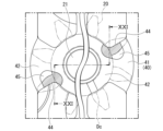
- FIG. 4 is a view of the body according to the embodiment as seen from the inside in the axial direction.
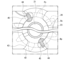
- FIG. 4 is a view of the cover according to the embodiment as viewed from the inside in the axial direction.
- 5A and 5B are diagrams showing cutout grooves formed in a body according to the embodiment.
- 6A and 6B are diagrams illustrating inner grooves formed in a cover according to an embodiment.
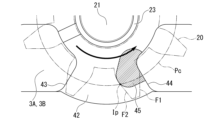
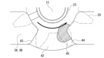
- 5A to 5C are diagrams illustrating the outer shape of a cutout groove formed in a body according to the embodiment.
- 6A and 6B are diagrams illustrating a variation in the high-pressure oil pressing area accompanying rotation of the second gear according to the embodiment.
- FIG. 18 is a diagram illustrating the variation in the high-pressure oil pressing area following FIG. 17 .
- FIG. 19 is a diagram illustrating the variation in the high-pressure oil pressing area following FIG. 18 .
- FIG. 16 is an explanatory diagram of the operation of the external gear pump according to the embodiment, including a cross section taken along the line XX-XX in FIG. 15 .
- FIG. 15 is an explanatory diagram of the operation of the external gear pump according to the embodiment, including a cross section taken along the line XXI-XXI in FIG. 14 .
- an external gear pump mounted on a diesel engine (one example of an engine) will be described as an external gear pump.
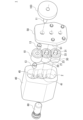
- Fig. 1 is a perspective view of an external gear pump 1 according to an embodiment of the present invention.
- Fig. 2 is an exploded perspective view of the external gear pump 1 according to an embodiment of the present invention.
- the external gear pump 1 is a triple oil pump in which three pump gears 10, 20, and 30 mesh with each other.
- the three pump gears 10, 20, and 30 are composed of a first gear 10, a second gear 20, and a third gear 30.
- the external gear pump 1 includes the first gear 10 that is driven to rotate by a drive source, a second gear 20 that meshes with the first gear 10 and rotates in a driven manner, a third gear 30 that meshes with the second gear 20 and rotates in a driven manner, a body 40 that has a first inner surface portion 41 that faces one side surface of the first gear 10, the second gear 20, and the third gear 30, and a cover 50 that has a second inner surface portion 51 that faces the other side surface of the first gear 10, the second gear 20, and the third gear 30.
- the first inner side surface portion 41 of the body 40 will also be referred to as the "gear chamber bottom surface”
- the second inner side surface portion 51 of the cover 50 will also be referred to as the "cover mounting surface.”
- the pump gears 10, 20, 30 may be arranged along a vertical line.
- the pump gears 10, 20, 30 may be arranged vertically in the order of first gear 10, second gear 20, and third gear 30 from above.
- the pump gears 10, 20, 30 may be arranged along a horizontal line, without being limited to the above.
- the first gear 10, which is the drive gear is not limited to being arranged on the side of the oil pump, but may be arranged on the center side.
- the arrangement of the pump gears 10, 20, 30 can be changed according to the design specifications.
- pump gears 10, 20, and 30 each have the same shape.
- pump gears 10, 20, and 30 are not limited to the above, and at least a portion of each may have a different shape.
- the shape of each of pump gears 10, 20, and 30 can be changed according to design specifications.
- the number of teeth on pump gears 10, 20, and 30 is 8. Note that the number of teeth on pump gears 10, 20, and 30 is not limited to the above, and may be 7 or less, or 9 or more. For example, the number of teeth on pump gears 10, 20, and 30 can be changed according to the design specifications.
- FIG. 3 is a perspective view of an engine 100 equipped with the external gear pump 1 according to the embodiment.
- the external gear pump 1 is disposed under a crankcase 101 of an engine 100.
- a pump drive gear 103 rotates in conjunction with a crankshaft 102 of the engine 100, which is a drive source.
- the rotational force of the pump drive gear 103 rotates pump gears 10, 20, and 30, which mesh with each other.
- the rotation of the pump gears 10, 20, and 30 pumps oil from an oil pan 104 located under the crankcase 101.
- the pumped oil is sucked into an internal flow path 2 of the external gear pump 1 through a suction port of the external gear pump 1.
- the external gear pump 1 changes the spatial volume of the meshing portion by the rotation of each pump gear 10, 20, 30, and draws oil from the oil pan 104 into the internal flow path 2 of the external gear pump 1.
- the drawn oil is pumped to the discharge port of the external gear pump 1 by the rotation of the pump gears 10, 20, 30.
- the pumped oil is sent to each sliding part (for example, the sliding parts of the cylinder 105 and piston 106 of the engine 100).
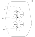
- Fig. 4 is a perspective view illustrating the oil flow in the external gear pump 1 according to the embodiment.
- Fig. 5 is a perspective view illustrating the oil flow in the internal flow passage 2 of the external gear pump 1 according to the embodiment.
- Fig. 6 is a diagram illustrating the oil flow in the gear chamber of the external gear pump 1 according to the embodiment. 4 to 6, suction ports 3A, 3B through which oil is sucked and discharge ports 4A, 4B through which oil is discharged are formed in the body 40.
- the first gear 10, the second gear 20, and the third gear 30 are configured to rotate while meshing with one another, thereby pressure-feeding the oil from the suction ports 3A, 3B to the discharge ports 4A, 4B.
- oil sucked from the oil pan 104 through the suction ports 3A and 3B is divided and flows toward each pump gear 10, 20, and 30.
- part of the divided oil flows from the suction port 3A to the discharge port 4A in the direction of the arrow W1 in FIG. 6 due to the rotation of the first gear 10 in the direction of the arrow R1 in FIG. 6 (clockwise).
- part of the divided oil flows from the suction port 3B to the discharge port 4A in the direction of the arrow W2 in FIG. 6 due to the rotation of the second gear 20 in the direction of the arrow R2 in FIG. 6 (counterclockwise), and also flows from the suction port 3A to the discharge port 4B in the direction of the arrow W3 in FIG. 6.
- part of the divided oil flows from the suction port 3B to the discharge port 4B in the direction of the arrow W4 in FIG. 6 due to the rotation of the third gear 30 in the direction of the arrow R3 in FIG. 6 (clockwise).
- the oil pumped to each discharge port 4A, 4B joins together and is sent out to the outside of the external gear pump 1.
- the pumped oil is used for lubrication or cooling of each sliding part.
- the relief valve 60 opens and the oil is diverted to a bypass flow path (not shown).
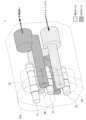
- Fig. 7 is a perspective view illustrating the flow of bearing lubricating oil in the external gear pump 1 according to the embodiment.
- Fig. 8 is a perspective view illustrating the flow of bearing lubricating oil in the first gear 10 according to the embodiment.
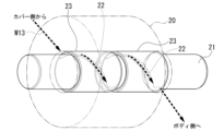
- Fig. 9 is a perspective view illustrating the flow of bearing lubricating oil in the second gear 20 according to the embodiment.
- Fig. 10 is a perspective view illustrating the flow of bearing lubricating oil in the third gear 30 according to the embodiment.
- Fig. 11 is a view including a cross section of the external gear pump 1 according to the embodiment cut along a plane including the rotation axes of the pump gears 10, 20, and 30.
- the bearing lubricating oil flows to lubricate the bearings and prevent seizure of the rotating parts due to the rotation of the pump gears 10, 20, and 30.
- the bearing lubricating oil flows from the high pressure side to the low pressure side.
- the bearing lubricating oil flows into the oil groove on the discharge side (high pressure side), flows through the oil groove of the bearing, and flows out to the oil groove on the suction side (low pressure side).
- the external gear pump 1 further includes shafts 11, 21, 31 (first shaft 11, second shaft 21, and third shaft 31) that run along the rotation axes of the pump gears 10, 20, 30, and bearings 13, 23, 33 (first bearing 13, second bearing 23, and third bearing 33) that support the shafts 11, 21, 31 and have oil grooves formed therein.
- the central axes of the three shafts 11, 21, 31 are arranged parallel to one another.
- the central axes of the shafts 11, 21, 31 may be arranged on the same vertical plane.
- the shafts 11, 21, 31 may be arranged in the order of the first shaft 11, the second shaft 21, and the third shaft 31 from vertically above.
- the central axes of the shafts 11, 21, 31 are not limited to the above, and may be arranged on different vertical planes.
- the central axes of the shafts 11, 21, 31 may be arranged on a horizontal plane.
- the arrangement of the shafts 11, 21, 31 can be changed according to the design specifications.
- the first shaft 11 extends in the axial direction along the rotation axis of the first gear 10. One end of the first shaft 11 is fixed to the pump drive gear 103. The first shaft 11 is longer in the axial direction than the second shaft 21 and the third shaft 31 by the amount that it is fixed to the pump drive gear 103.
- the first bearing 13 is disposed between the inner circumferential surface of the through hole of the body 40 and the outer circumferential surface of the first shaft 11, and between the inner circumferential surface of the through hole of the cover 50 and the outer circumferential surface of the first shaft 11.
- the first shaft 11 and the first gear 10 rotate together as a unit due to the rotation of the pump drive gear 103.
- the first gear 10, the first shaft 11, and the first bearing 13 on the body 40 side are configured to allow oil to flow through the oil groove 12 from the discharge ports 4A, 4B toward the body 40 side in the direction of arrow W11.
- the first gear 10, the first shaft 11, and the first bearing 13 on the cover 50 side are configured to allow oil to flow through the oil groove 12 from the cover 50 side to the outside of the external gear pump 1 in the direction of arrow W12.
- the second shaft 21 extends in the axial direction along the rotation axis of the second gear 20.
- One end of the second shaft 21 is fixed to the body 40.
- the other end of the second shaft 21 is fixed to the cover 50.
- the second bearing 23 is disposed between the inner peripheral surface of the second gear 20 and the outer peripheral surface of the second shaft 21.
- the second gear 20 rotates about the second shaft 21 by meshing with the first gear 10.
- the second gear 20, the second shaft 21 and the second bearing 23 are configured to allow oil to flow through the oil groove 22 in the direction of the arrow W13 from the cover 50 side to the body 40 side.
- the third shaft 31 extends in the axial direction along the rotation axis of the third gear 30.
- One end of the third shaft 31 is fixed to the body 40.
- the other end of the third shaft 31 is fixed to the cover 50.
- the third bearing 33 is disposed between the inner peripheral surface of the third gear 30 and the outer peripheral surface of the third shaft 31.
- the third gear 30 rotates about the third shaft 31 by meshing with the second gear 20.
- the third gear 30, the third shaft 31 and the third bearing 33 are configured to allow oil to flow in the direction of the arrow W14 from the body 40 side toward the cover 50 side through the oil groove 32.
- the bearings 13, 23, and 33 have the same shape. Note that the shapes of the bearings 13, 23, and 33 are not limited to those described above and can be changed according to design specifications. In the illustrated example, two bearings 13, 23, and 33 are disposed on each of the shafts 11, 21, and 31. Note that the number of bearings 13, 23, and 33 is not limited to the above and can be changed according to design specifications. In the illustrated example, the oil grooves 12, 22, and 32 are formed in a spiral shape along the axial direction on the inner or outer circumferential surfaces of the bearings 13, 23, and 33, respectively. Note that the shapes of the oil grooves 12, 22, and 32 are not limited to those described above and can be changed according to design specifications.
- FIG. 12 is a view of the body 40 according to the embodiment as seen from the inside in the axial direction.
- FIG. 13 is a view of the cover 50 according to the embodiment as seen from the inside in the axial direction.
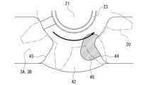
- FIG. 14 is a view showing the notch groove 45 formed in the body 40 according to the embodiment.
- FIG. 15 is a view showing the inner groove 52 formed in the cover 50 according to the embodiment.
- FIG. 16 is a view explaining the outer shape of the notch groove 45 formed in the body 40 according to the embodiment.
- the arrows W11 to W14 indicate the flow direction of the bearing lubricating oil flowing through the oil groove of the shaft insertion part on the gear chamber bottom surface or the cover mounting surface.
- FIG. 12 and FIG. 13 the arrows W11 to W14 indicate the flow direction of the bearing lubricating oil flowing through the oil groove of the shaft insertion part on the gear chamber bottom surface or the cover mounting surface.
- the area where the second gear 20 and the notch groove 45 overlap as viewed from the axial direction is shown by hatching.
- the formation area of the inner groove 52 as viewed from the axial direction is shown by hatching.
- the formation area of the notch groove 45 as viewed from the axial direction is shown by hatching. 12 to 16, the first inner side surface portion 41 (gear chamber bottom surface) has a partition portion 42 that separates the suction ports 3A, 3B from the discharge ports 4A, 4B.
- the partition 42 is formed in a portion separating one of the suction ports 3A and the discharge port 4B, and a portion separating the other of the suction ports 3B and the discharge port 4A, as viewed in the axial direction.
- the partition 42 is formed in an area overlapping a portion of the second gear 20 as viewed in the axial direction.
- the partition 42 is formed in two areas sandwiching the insertion portion of the second shaft 21 as viewed in the axial direction.
- the partition 42 has a discharge edge 44 that forms the edge of the discharge ports 4A, 4B.
- the discharge edge 44 extends in a direction perpendicular to the central axis of the second shaft 21 as viewed in the axial direction.
- a notched groove 45 is formed in the discharge edge 44.
- a portion of the notch groove 45 is positioned more inward than the root circle Dc of the second gear 20.
- the root circle Dc means a circle that passes through the roots of the teeth of the second gear 20 when viewed from the axial direction and is concentric with the pitch circle Pc.
- the pitch circle Pc means a circle whose radius is the distance from the center of the second gear 20 to the point where the second gear 20 contacts the first gear 10 or the third gear 30 when viewed from the axial direction.
- part of the outer shape of the cutout groove 45 overlaps with the pitch circle Pc of the second gear 20.
- part of the outer shape of the cutout groove 45 overlaps with the bisection point Bp that bisects the distance between the bottom circle Dc and the outer shape of the second bearing 23 in the radial direction perpendicular to the axial direction.
- Fig. 17 is a diagram for explaining the variation in the high-pressure oil pressing area accompanying the rotation of the second gear 20 according to the embodiment.
- Fig. 18 is a diagram for explaining the variation in the high-pressure oil pressing area following Fig. 17.
- Fig. 19 is a diagram for explaining the variation in the high-pressure oil pressing area following Fig. 18.
- Fig. 17 corresponds to a diagram when the first surface F1 of the tooth of the second gear 20 facing downstream in the rotation direction of the second gear 20 overlaps with the discharge edge 44 as viewed from the axial direction.
- the outer shape of the notched groove 45 when viewed from the axial direction, when a first surface F1 of the tooth of the second gear 20 facing downstream in the rotation direction of the second gear 20 overlaps with the discharge edge 44, a part of the outer shape of the notched groove 45 overlaps with an intersection point Ip where a second surface F2 of the tooth of the second gear 20 facing upstream in the rotation direction of the second gear 20 intersects with the pitch circle Pc.
- the outer shape of the notched groove 45 includes a curved shape that overlaps with the pitch circle Pc, the bisection point Bp, and the intersection point Ip.
- the partition wall portion 42 has a suction edge 43 that forms the edge of the suction ports 3A, 3B.
- a portion of the notch groove 45 is formed in the partition wall portion 42 from a portion between the suction edge 43 and the discharge edge 44 to the discharge edge 44.
- the opening area of the portion of the notch groove 45 increases as the second gear 20 rotates. Also, the depth of the portion of the notch groove 45 increases as the second gear 20 rotates.
- the opening area of a portion of the notched groove 45 changes.
- the opening area of a portion of the notched groove 45 changes in the radial direction perpendicular to the axial direction of the second shaft 21, and the opening area changes in the rotational direction of the second gear 20 (the circumferential direction around the second shaft 21).
- the manner in which the opening area of a portion of the notched groove 45 changes when viewed from the axial direction is not limited to the above, and can be changed according to design specifications.
- the opening area of a portion of the notched groove 45 changes.
- the opening area of a portion of the notched groove 45 may change in a radial direction perpendicular to the axial direction. Note that the manner in which the opening area of a portion of the notched groove 45 changes when viewed in cross section is not limited to the above and can be changed according to design specifications.
- an inner groove 52 through which oil flows is formed in the second inner side surface portion 51 (cover mounting surface). Also referring to FIG. 16, the notched groove 45 is formed in the first inner side surface portion 41 so that the high-pressure oil pressing area as viewed in the axial direction is approximately the same as that of the inner groove 52.
- the inner groove 52 is composed of an annular portion that follows the outer periphery of the shaft insertion portion on the cover mounting surface, and an extension portion that extends radially from a part of the annular portion.
- the entire inner groove 52 is positioned on the inner side of the bottom circle Dc when viewed from the axial direction. Therefore, on the cover 50 side where the inner groove 52 is formed, the area pressed against the high-pressure oil does not change as the second gear 20 rotates.
- a portion of the notch groove 45 is positioned on the outer periphery side of the root circle Dc when viewed from the axial direction. Therefore, on the body 40 side where the notch groove 45 is formed, the area pressed against the high-pressure oil changes as the second gear 20 rotates.
- bearing lubricating oil flows in from the oil groove on the discharge side (high pressure side), flows through the oil groove of the bearing, and flows out to the oil groove on the suction side (low pressure side).
- the high pressure oil flows through the gaps on the side of the pump gears 10, 20, 30, and presses the pump gears 10, 20, 30 in one direction. This causes the pump gears 10, 20, 30 to become biased (misaligned in the axial direction).
- the second gear 20, the second shaft 21, and the second bearing 23 are configured to allow oil to flow from the cover 50 side toward the body 40 side through the oil groove 22. Therefore, the second gear 20 is pressed toward the body 40 side and biased toward the body 40 side.
- the gap between the second gear 20 and the body 40 narrows, and when the oil is discharged, the high-pressure oil flows through the tiny gap at high speed and is released into the low-pressure area (cavitation area). This makes it easier for cavitation and erosion due to cavitation to occur.
- a notched groove 45 is formed on the side of the body 40 (first inner side surface portion 41).
- the notched groove 45 is formed on the side of the body 40 so that it is equal to the pressing area of the second gear 20 by the high-pressure oil on the cover 50 side. This allows equal pressing forces to be applied from both sides of the second gear 20, balancing the second gear 20 and ensuring a gap on the side of the second gear 20.
- the high-pressure oil pressing area of the notched groove 45 as viewed from the axial direction is designated as A1
- the high-pressure oil pressing area of the inner groove 52 as viewed from the axial direction is designated as A2.
- the high-pressure oil pressing area ratio A1/A2 is not limited to the above and can be changed according to the design specifications.
- the external gear pump 1 of this embodiment includes the first gear 10 that is driven to rotate by the drive source, the second gear 20 that meshes with the first gear 10 and rotates accordingly, the third gear 30 that meshes with the second gear 20 and rotates accordingly, the body 40 having a first inner side surface portion 41 that faces one side surface of the first gear 10, the second gear 20, and the third gear 30, and the cover 50 having a second inner side surface portion 51 that faces the other side surface of the first gear 10, the second gear 20, and the third gear 30.
- the body 40 is formed with suction ports 3A and 3B through which oil is sucked and discharge ports 4A and 4B through which oil is discharged.
- the first gear 10, the second gear 20, and the third gear 30 are configured to rotate while meshing with each other, thereby pressure-feeding oil from the suction ports 3A and 3B to the discharge ports 4A and 4B.
- the first inner side surface portion 41 has a partition wall portion 42 separating the suction ports 3A, 3B from the discharge ports 4A, 4B, and has a discharge edge 44 which becomes the edge of the discharge ports 4A, 4B.
- a notched groove 45 is formed in the discharge edge 44.
- the notch groove 45 is formed in the discharge edge 44 of the partition wall portion 42 separating the suction ports 3A, 3B and the discharge ports 4A, 4B, so that the tooth grooves communicate with the notch groove 45 before communicating with the discharge ports 4A, 4B during the process of the rotation of the second gear 20.
- a portion of the cutout groove 45 is disposed on the inner peripheral side of the bottom circle Dc of the second gear 20 .
- the high-pressure oil pressing area will fluctuate with the rotation of the second gear 20.
- a part of the notched groove 45 is located on the inner periphery side of the bottom circle Dc of the second gear 20 as viewed in the axial direction, thereby making it possible to suppress the fluctuation in the high-pressure oil pressing area.
- a part of the outer shape of the cutout groove 45 overlaps with the pitch circle Pc of the second gear 20 when viewed in the axial direction. According to this configuration, it is possible to prevent the outer shape of the cutout groove 45 from becoming larger than necessary.
- the outer shape of the cutout groove 45 when viewed from the axial direction includes a curved shape that overlaps with the pitch circle Pc, the bisection point Bp, and the intersection point Ip.
- the partition wall portion 42 has an inlet edge 43 which is an edge of the inlets 3A, 3B.
- a part of the notched groove 45 is formed in the partition wall portion 42 from a portion between the inlet edge 43 and the discharge edge 44 to the discharge edge 44.
- the opening area of the part of the notched groove 45 increases with the rotation of the second gear 20.
- the opening area of a portion of the cutout groove 45 changes when viewed in the axial direction. This configuration improves design freedom in optimizing the opening area of the notched groove 45 .
- the opening area of a part of the notched groove 45 changes. This configuration improves design freedom in optimizing the opening area of the notched groove 45 .
- the external gear pump 1 further includes a second shaft 21 that extends in the axial direction along the rotation axis of the second gear 20 and has one end fixed to the body 40 and the other end fixed to the cover 50, and a second bearing 23 that is disposed between the inner circumferential surface of the second gear 20 and the outer circumferential surface of the second shaft 21 and has an oil groove 22 formed therein.
- the second gear 20, the second shaft 21, and the second bearing 23 are configured to allow oil to flow from the cover 50 side toward the body 40 side through the oil groove 22. For example, when high-pressure oil presses the second gear 20 from the cover 50 side toward the body 40 side, the second gear 20 is biased toward the body 40 side in the axial direction.
- the gap between the second gear 20 and the body 40 narrows, and the high-pressure oil flows through the minute gap at high speed when the oil is discharged and is released to the low-pressure portion (cavitation portion). Therefore, erosion due to cavitation is likely to occur.
- the notch groove 45 is formed on the body 40 side (first inner side surface portion 41) as described above, which is very beneficial in suppressing the occurrence of erosion due to cavitation.
- an inner groove 52 through which oil flows is formed in the second inner side surface portion 51.
- the notched groove 45 is formed in the first inner side surface portion 41 so that the high-pressure oil pressing area as viewed in the axial direction is approximately the same as that of the inner groove 52.
- the second gear 20 can be pushed with equal and balanced forces from both sides in the axial direction. Therefore, a gap can be secured between both sides of the second gear 20 and each of the first inner side surface portion 41 and the second inner side surface portion 51. Therefore, the occurrence of erosion due to cavitation can be more effectively suppressed.
- the external gear pump 1 of this embodiment is mounted on a diesel engine 100 . According to this configuration, in the external gear pump 1 mounted on the diesel engine 100, the occurrence of erosion due to cavitation can be suppressed.
- diesel engine oil pumps mainly use external gear pumps, in which a pump drive gear rotates in conjunction with the engine's crankshaft, and the torque of this rotation drives meshing pump gears to rotate.
- external gear pumps oil is introduced into the tooth grooves from the suction port as the pump gear rotates, and the oil is pumped to the discharge port by rotating the pump gear. The oil is discharged when the pressure in the tooth grooves of the pump gear changes from suction pressure to discharge pressure. Also, to prevent a decrease in pump efficiency, there are extremely small gaps between the two sides of the meshing pump gears and the bottom of the gear chamber and the cover mounting surface.
- a notched groove 45 is formed in the discharge edge 44 of the partition wall 42 that separates the suction ports 3A, 3B and the discharge ports 4A, 4B, making it possible to prevent a decrease in pump efficiency and suppress the occurrence of cavitation in the gaps between the side of the second gear 20 and the first inner side surface portion 41 (gear chamber bottom surface) and the second inner side surface portion 51 (cover mounting surface).
- high-pressure oil is introduced into the notched groove 45 that communicates with the discharge ports 4A, 4B, and the side of the second gear 20 on the inner periphery of the bottom circle Dc is filled with high-pressure oil.
- the high-pressure oil pushes back the second gear 20, which is biased to one side in the axial direction, thereby ensuring large gaps between both sides of the second gear 20 and the gear chamber bottom and cover mounting surface. This allows the flow rate of the high-pressure oil flowing through the gaps to be kept low, and the reduction in the flow rate of the high-pressure oil when released to the low-pressure side slows the drop in oil pressure. This makes it possible to suppress cavitation that occurs in the gaps with the sides of the second gear 20.
- the oil introduced into the tooth groove of the second gear 20 from the suction ports 3A and 3B moves to the discharge ports 4A and 4B as the pump gears 10, 20 and 30 rotate.
- the notch groove 45 is connected to the high-pressure side discharge ports 4A and 4B. Therefore, as shown in FIG. 17, when the tooth groove portion of the second gear 20 reaches the notch groove 45, the pressure in the tooth groove gradually increases. In the initial stage when the tooth groove portion of the second gear 20 reaches the notch groove 45, most of the notch groove 45 is covered by the second gear 20. Therefore, the pressure in the tooth groove of the second gear 20 gradually increases. In other words, the pressure in the tooth groove of the second gear 20 connected to the notch groove 45 increases slowly.
- a portion of the notch groove 45 is formed in the partition wall 42 from the area between the suction edge 43 and the discharge edge 44 to the discharge edge 44. Therefore, the gaps between the side surface of the second gear 20 and the bottom surface of the gear chamber and the cover mounting surface are not connected to the suction ports 3A and 3B. This makes it possible to avoid a decrease in pump efficiency due to the formation of the notch groove 45.
- a portion of the notched groove is disposed on the inner circumferential side of the bottom circle of the second gear as viewed from the axial direction, but this is not limited thereto.
- the entire notched groove may be disposed on the outer circumferential side of the bottom circle of the second gear as viewed from the axial direction.
- at least a portion of the notched groove may be disposed on the inner circumferential side of the bottom circle of the second gear as viewed from the axial direction.
- the arrangement of the notched groove with respect to the bottom circle of the second gear can be changed according to design specifications.
- a portion of the outer shape of the notched groove overlaps with the pitch circle of the second gear when viewed from the axial direction, but this is not limited to this.
- a portion of the outer shape of the notched groove does not have to overlap with the pitch circle of the second gear when viewed from the axial direction.
- the arrangement of the outer shape of the notched groove relative to the pitch circle of the second gear can be changed according to the design specifications.
- a portion of the outer shape of the notched groove overlaps with the bisection point that halves the distance between the root circle and the outer shape of the bearing of the second gear in the radial direction perpendicular to the axial direction, but this is not limited to this.
- a portion of the outer shape of the notched groove, as viewed from the axial direction does not have to overlap with the bisection point.
- the arrangement of the outer shape of the notched groove relative to the bisection point can be changed according to the design specifications.
- the outer shape of the cutout groove when viewed from the axial direction includes a curved shape that overlaps with the pitch circle, the bisection point, and the intersection point, but this is not limited to this.
- the outer shape of the cutout groove when viewed from the axial direction may include a linear shape that overlaps with the pitch circle, the bisection point, and the intersection point.
- the arrangement of the outer shape of the cutout groove with respect to the pitch circle, the bisection point, and the intersection point can be changed according to the design specifications.
- the partition has a suction edge that is the edge of the suction port, and a portion of the notch groove is formed in the partition from a portion between the suction edge and the discharge edge to the discharge edge, and an example has been described in which the opening area increases with rotation of the second gear, but this is not limited to the above.
- the opening area of the entire notch groove may be constant from a portion between the suction edge and the discharge edge to the discharge edge in the partition.
- at least a portion of the notch groove may be formed in the partition from a portion between the suction edge and the discharge edge to the discharge edge, and the opening area may increase with rotation of the second gear.
- the size of the opening area of the notch groove with rotation of the second gear can be changed according to the design specifications.
- the opening area of a portion of the notch groove changes when viewed from the axial direction, but this is not limited to this.
- the opening area of the entire notch groove may not change when viewed from the axial direction.
- the opening area of at least a portion of the notch groove may change when viewed from the axial direction.
- the manner in which the opening area of the notch groove changes when viewed from the axial direction can be changed according to the design specifications.
- the opening area of a portion of the notch groove changes when viewed in cross section along a plane parallel to the axial direction, but this is not limited to this.
- the opening area of the entire notch groove may not change when viewed in cross section.
- the opening area of at least a portion of the notch groove may change when viewed in cross section.
- the manner in which the opening area of the notch groove changes when viewed in cross section can be changed according to the design specifications.
- the notch groove is formed in the first inner surface portion and not formed in the second inner surface portion, but this is not limited thereto.
- the notch groove may be formed in each of the first inner surface portion and the second inner surface portion.
- the external gear pump further includes a shaft extending in the axial direction along the rotation axis of the second gear, one end of which is fixed to the body and the other end of which is fixed to the cover, and a bearing disposed between the inner peripheral surface of the second gear and the outer peripheral surface of the shaft, in which an oil groove is formed.
- the second gear, shaft, and bearing are configured to allow oil to flow from the cover side to the body side through the oil groove, but this is not limiting.
- the second gear, shaft, and bearing may be configured to allow oil to flow from the body side to the cover side through the oil groove.
- the flow direction of oil through the oil groove can be changed according to design specifications.
- an example was given in which an inner groove through which oil flows is formed in the second inner surface portion, and the notched groove is formed in the first inner surface portion so that the high-pressure oil pressing area as viewed in the axial direction is approximately the same as that of the inner groove, but this is not limited to this.
- the notched groove may be formed in the first inner surface portion so that the high-pressure oil pressing area as viewed in the axial direction is different from that of the inner groove.
- the relationship between the high-pressure oil pressing area of the notched groove and the inner groove as viewed in the axial direction can be changed according to the design specifications.
- the external gear pump is described as being mounted on a diesel engine, but this is not limiting.
- the external gear pump may be mounted on an engine other than a diesel engine.
- the external gear pump may be mounted on a power source other than an engine.
- the target on which the external gear pump is mounted can be changed depending on the design specifications.
- an outer shape of the notched groove When viewed from the axial direction, an outer shape of the notched groove includes a curved shape overlapping with the pitch circle, the bisection point, and the intersection point. 6.
- the partition portion has a suction edge that becomes an edge of the suction port, At least a portion of the notch groove is formed in the partition wall from a portion between the suction edge and the discharge edge to the discharge edge, and an opening area of the notch groove increases with rotation of the second gear.
- the second inner side surface portion is formed with an inner groove through which the oil flows, the notched groove is formed in the first inner side surface portion so that a high-pressure oil pressing area as viewed in the axial direction is substantially the same as that of the inner groove.
- the external gear pump is mounted on an engine. 13.
- the external gear pump according to any one of claims 1 to 12.
Landscapes
- Engineering & Computer Science (AREA)
- Mechanical Engineering (AREA)
- General Engineering & Computer Science (AREA)
- Rotary Pumps (AREA)
- Details And Applications Of Rotary Liquid Pumps (AREA)
Abstract
この外接ギヤポンプは、駆動源により回転駆動される第1ギヤと、前記第1ギヤに噛み合い従動回転する第2ギヤと、前記第2ギヤに噛み合い従動回転する第3ギヤと、前記第1ギヤ、前記第2ギヤ及び前記第3ギヤの一方の側面に面する第1内側面部を有するボディと、前記第1ギヤ、前記第2ギヤ及び前記第3ギヤの他方の側面に面する第2内側面部を有するカバーと、を備え、前記ボディには、オイルが吸い込まれる吸込口と前記オイルが吐き出される吐出口とが形成され、前記第1ギヤ、前記第2ギヤ及び前記第3ギヤは、互いに噛み合い回転することによって前記オイルを前記吸込口から前記吐出口に向けて圧送するよう構成され、前記第1内側面部及び前記第2内側面部の少なくとも一方は、前記吸込口と前記吐出口とを隔てる隔壁部に、前記吐出口の端縁となる吐出端縁を有し、前記吐出端縁には、切欠溝が形成される。
Description
本発明は、外接ギヤポンプに関する。
本発明は、2023年6月13日に、日本に出願された特願2023-096865号に基づき優先権を主張し、その内容をここに援用する。
本発明は、2023年6月13日に、日本に出願された特願2023-096865号に基づき優先権を主張し、その内容をここに援用する。
外接ギヤポンプには、2つのポンプギヤが噛み合う2連式のオイルポンプと、3つのポンプギヤが噛み合う3連式のオイルポンプと、がある。特許文献1には、2連式の外接ギヤポンプが開示されている。特許文献1の外接ギヤポンプは、各ポンプギヤの両側面に配置されたサイドプレートを備える。サイドプレートには、各ポンプギヤの回転軸を結ぶ直線方向に延在する吸入側逃げ部及び吐出側逃げ部が傾斜面により形成される。特許文献1には、3連式の外接ギヤポンプは開示されていない。
3連式の外接ギヤポンプでは、オイルを吸込口から吐出口まで圧送する区間で十分な長さを確保することが困難である。そのため、オイルを圧送する際、ギヤ開放時に歯溝内の圧力が急激に上昇する場合がある。この場合、オイルの流れの中で圧力差により短時間に泡の発生と消滅とが起きる、いわゆるキャビテーションが発生する可能性が高くなる。キャビテーションが発生すると、ギヤ室底部にエロージョン(機械的な摩耗)が発生する虞がある。そのため、キャビテーションによるエロージョンの発生を抑制する上で改善の余地がある。
そこで本発明は、キャビテーションによるエロージョンの発生を抑制することができる外接ギヤポンプを提供することを目的とする。
本発明の一態様に係る外接ギヤポンプは、駆動源により回転駆動される第1ギヤと、前記第1ギヤに噛み合い従動回転する第2ギヤと、前記第2ギヤに噛み合い従動回転する第3ギヤと、前記第1ギヤ、前記第2ギヤ及び前記第3ギヤの一方の側面に面する第1内側面部を有するボディと、前記第1ギヤ、前記第2ギヤ及び前記第3ギヤの他方の側面に面する第2内側面部を有するカバーと、を備え、前記ボディには、オイルが吸い込まれる吸込口と前記オイルが吐き出される吐出口とが形成され、前記第1ギヤ、前記第2ギヤ及び前記第3ギヤは、互いに噛み合い回転することによって前記オイルを前記吸込口から前記吐出口に向けて圧送するよう構成され、前記第1内側面部及び前記第2内側面部の少なくとも一方は、前記吸込口と前記吐出口とを隔てる隔壁部に、前記吐出口の端縁となる吐出端縁を有し、前記吐出端縁には、切欠溝が形成される。
上記態様によれば、キャビテーションによるエロージョンの発生を抑制することができる。
以下、本発明の実施形態について図面を参照して説明する。実施形態においては、外接ギヤポンプとして、ディーゼルエンジン(エンジンの一例)に搭載された外接ギヤポンプを挙げて説明する。
以下の説明において、例えば「平行」や「直交」、「中心」、「同軸」等の相対的又は絶対的な配置を示す表現は、厳密にそのような配置や状態を意味するのみならず、公差や同じ機能が得られる程度の角度や距離をもって相対的に変位している配置や状態をも含むものとする。以下の説明に用いる図面では、各部材を認識可能な大きさとするため、各部材の縮尺を適宜変更して示す場合がある。
<外接ギヤポンプ>
図1は、実施形態に係る外接ギヤポンプ1の斜視図である。図2は、実施形態に係る外接ギヤポンプ1の分解斜視図である。
図1及び図2に示すように、外接ギヤポンプ1は、3つのポンプギヤ10,20,30が噛み合う3連式のオイルポンプである。3つのポンプギヤ10,20,30は、第1ギヤ10、第2ギヤ20及び第3ギヤ30で構成される。外接ギヤポンプ1は、駆動源により回転駆動される第1ギヤ10と、第1ギヤ10に噛み合い従動回転する第2ギヤ20と、第2ギヤ20に噛み合い従動回転する第3ギヤ30と、第1ギヤ10、第2ギヤ20及び第3ギヤ30の一方の側面に面する第1内側面部41を有するボディ40と、第1ギヤ10、第2ギヤ20及び第3ギヤ30の他方の側面に面する第2内側面部51を有するカバー50と、を備える。以下、ボディ40の第1内側面部41を「ギヤ室底面」、カバー50の第2内側面部51を「カバー取付面」ともいう。
図1は、実施形態に係る外接ギヤポンプ1の斜視図である。図2は、実施形態に係る外接ギヤポンプ1の分解斜視図である。
図1及び図2に示すように、外接ギヤポンプ1は、3つのポンプギヤ10,20,30が噛み合う3連式のオイルポンプである。3つのポンプギヤ10,20,30は、第1ギヤ10、第2ギヤ20及び第3ギヤ30で構成される。外接ギヤポンプ1は、駆動源により回転駆動される第1ギヤ10と、第1ギヤ10に噛み合い従動回転する第2ギヤ20と、第2ギヤ20に噛み合い従動回転する第3ギヤ30と、第1ギヤ10、第2ギヤ20及び第3ギヤ30の一方の側面に面する第1内側面部41を有するボディ40と、第1ギヤ10、第2ギヤ20及び第3ギヤ30の他方の側面に面する第2内側面部51を有するカバー50と、を備える。以下、ボディ40の第1内側面部41を「ギヤ室底面」、カバー50の第2内側面部51を「カバー取付面」ともいう。
例えば、ポンプギヤ10,20,30は、鉛直線に沿って配置されてもよい。例えば、ポンプギヤ10,20,30は、鉛直上方から第1ギヤ10、第2ギヤ20、第3ギヤ30の順に配置されてもよい。例えば、ポンプギヤ10,20,30は、上記に限らず、水平線に沿って配置されてもよい。例えば、ドライブギヤである第1ギヤ10は、オイルポンプのサイド側に配置されることに限らず、センタ側に配置されてもよい。例えば、ポンプギヤ10,20,30の配置態様は、設計仕様に応じて変更することができる。
例えば、ポンプギヤ10,20,30は、それぞれ同じ形状を有する。例えば、ポンプギヤ10,20,30は、上記に限らず、それぞれの少なくとも一部が互いに異なる形状を有してもよい。例えば、ポンプギヤ10,20,30の各々の形状は、設計仕様に応じて変更することができる。
図の例では、ポンプギヤ10,20,30の歯数は、8である。なお、ポンプギヤ10,20,30の歯数は、上記に限らず、7以下でもよいし、9以上でもよい。例えば、ポンプギヤ10,20,30の歯数は、設計仕様に応じて変更することができる。
<エンジン>
図3は、実施形態に係る外接ギヤポンプ1を搭載したエンジン100の斜視図である。
図3を併せて参照し、外接ギヤポンプ1は、エンジン100のクランクケース101の下部に配置される。ポンプ駆動ギヤ103は、駆動源であるエンジン100のクランクシャフト102に連動して回転する。ポンプ駆動ギヤ103の回転力によって、互いに噛み合うポンプギヤ10,20,30が回転する。ポンプギヤ10,20,30の回転により、クランクケース101下部のオイルパン104からオイルがくみ上げられる。くみ上げられたオイルは、外接ギヤポンプ1の吸込口を通じて外接ギヤポンプ1の内部流路2へ吸い込まれる。
図3は、実施形態に係る外接ギヤポンプ1を搭載したエンジン100の斜視図である。
図3を併せて参照し、外接ギヤポンプ1は、エンジン100のクランクケース101の下部に配置される。ポンプ駆動ギヤ103は、駆動源であるエンジン100のクランクシャフト102に連動して回転する。ポンプ駆動ギヤ103の回転力によって、互いに噛み合うポンプギヤ10,20,30が回転する。ポンプギヤ10,20,30の回転により、クランクケース101下部のオイルパン104からオイルがくみ上げられる。くみ上げられたオイルは、外接ギヤポンプ1の吸込口を通じて外接ギヤポンプ1の内部流路2へ吸い込まれる。
このように、外接ギヤポンプ1は、各ポンプギヤ10,20,30の回転により噛み合い部の空間容積を変化させ、オイルパン104から外接ギヤポンプ1の内部流路2へオイルを吸い込む。吸い込まれたオイルは、ポンプギヤ10,20,30の回転により、外接ギヤポンプ1の吐出口へ圧送される。圧送されたオイルは、各摺動部(例えば、エンジン100のシリンダ105及びピストン106の摺動部など)へ送り出される。
<オイルの流れ>
図4は、実施形態に係る外接ギヤポンプ1のオイル流れを説明する斜視図である。図5は、実施形態に係る外接ギヤポンプ1の内部流路2のオイル流れを説明する斜視図である。図6は、実施形態に係る外接ギヤポンプ1のギヤ室のオイル流れを説明する図である。
図4から図6を併せて参照し、ボディ40には、オイルが吸い込まれる吸込口3A,3Bとオイルが吐き出される吐出口4A,4Bとが形成される。第1ギヤ10、第2ギヤ20及び第3ギヤ30は、互いに噛み合い回転することによってオイルを吸込口3A,3Bから吐出口4A,4Bに向けて圧送するよう構成される。
図4は、実施形態に係る外接ギヤポンプ1のオイル流れを説明する斜視図である。図5は、実施形態に係る外接ギヤポンプ1の内部流路2のオイル流れを説明する斜視図である。図6は、実施形態に係る外接ギヤポンプ1のギヤ室のオイル流れを説明する図である。
図4から図6を併せて参照し、ボディ40には、オイルが吸い込まれる吸込口3A,3Bとオイルが吐き出される吐出口4A,4Bとが形成される。第1ギヤ10、第2ギヤ20及び第3ギヤ30は、互いに噛み合い回転することによってオイルを吸込口3A,3Bから吐出口4A,4Bに向けて圧送するよう構成される。
例えば、オイルパン104から吸込口3A,3Bを通じて吸い込まれたオイルは、分流して各ポンプギヤ10,20,30へ向けて流れる。例えば、分流したオイルの一部は、第1ギヤ10の図6の矢印R1方向(時計回り)の回転により、吸込口3Aから吐出口4Aへ向けて図6の矢印W1方向へ流れる。例えば、分流したオイルの一部は、第2ギヤ20の図6の矢印R2方向(反時計回り)の回転により、吸込口3Bから吐出口4Aへ図6の矢印W2方向へ流れるとともに、吸込口3Aから吐出口4Bへ図6の矢印W3方向へ流れる。例えば、分流したオイルの一部は、第3ギヤ30の図6の矢印R3方向(時計回り)の回転により、オイルは吸込口3Bから吐出口4Bへ図の矢印W4方向へ流れる。
例えば、各吐出口4A,4Bへ圧送されたオイルは、合流して外接ギヤポンプ1の外部へ送り出される。例えば、送り出されたオイルは、各摺動部の潤滑又は冷却などに利用される。例えば、オイルの圧送により外接ギヤポンプ1の内部流路2の油圧が規定値に達した場合は、リリーフバルブ60が開くことにより、オイルは不図示のバイパス流路へ流される。
<軸受潤滑オイル流れ>
図7は、実施形態に係る外接ギヤポンプ1の軸受潤滑オイル流れを説明する斜視図である。図8は、実施形態に係る第1ギヤ10の軸受潤滑オイル流れを説明する斜視図である。図9は、実施形態に係る第2ギヤ20の軸受潤滑オイル流れを説明する斜視図である。図10は、実施形態に係る第3ギヤ30の軸受潤滑オイル流れを説明する斜視図である。図11は、実施形態に係る外接ギヤポンプ1を各ポンプギヤ10,20,30の回転軸を含む面で切断した断面を含む図である。
軸受潤滑オイルは、ポンプギヤ10,20,30の回転による回転部の焼き付きを防ぐため、軸受を潤滑するために流れる。軸受潤滑オイルは、高圧側から低圧側へ流れる。軸受潤滑オイルは、吐出側(高圧側)の油溝から流入し、軸受の油溝を流れて吸込側(低圧側)の油溝へ流出する。
図7は、実施形態に係る外接ギヤポンプ1の軸受潤滑オイル流れを説明する斜視図である。図8は、実施形態に係る第1ギヤ10の軸受潤滑オイル流れを説明する斜視図である。図9は、実施形態に係る第2ギヤ20の軸受潤滑オイル流れを説明する斜視図である。図10は、実施形態に係る第3ギヤ30の軸受潤滑オイル流れを説明する斜視図である。図11は、実施形態に係る外接ギヤポンプ1を各ポンプギヤ10,20,30の回転軸を含む面で切断した断面を含む図である。
軸受潤滑オイルは、ポンプギヤ10,20,30の回転による回転部の焼き付きを防ぐため、軸受を潤滑するために流れる。軸受潤滑オイルは、高圧側から低圧側へ流れる。軸受潤滑オイルは、吐出側(高圧側)の油溝から流入し、軸受の油溝を流れて吸込側(低圧側)の油溝へ流出する。
図7から図11を併せて参照し、外接ギヤポンプ1は、各ポンプギヤ10,20,30の回転軸に沿うシャフト11,21,31(第1シャフト11、第2シャフト21及び第3シャフト31)と、各シャフト11,21,31を支持し油溝が形成された軸受13,23,33(第1軸受13、第2軸受23及び第3軸受33)と、を更に備える。
3つのシャフト11,21,31の中心軸は、互いに平行に配置される。例えば、シャフト11,21,31の中心軸は、同一の鉛直面上に配置されてもよい。例えば、シャフト11,21,31は、鉛直上方から第1シャフト11、第2シャフト21、第3シャフト31の順に配置されてもよい。例えば、シャフト11,21,31の中心軸は、上記に限らず、それぞれ異なる鉛直面上に配置されてもよい。例えば、シャフト11,21,31の中心軸は、水平面上に配置されてもよい。例えば、シャフト11,21,31の配置態様は、設計仕様に応じて変更することができる。
第1シャフト11は、第1ギヤ10の回転軸に沿う軸方向に延びる。第1シャフト11の一端は、ポンプ駆動ギヤ103に固定される。第1シャフト11は、ポンプ駆動ギヤ103に固定される分、第2シャフト21及び第3シャフト31よりも軸方向に長い。
第1軸受13は、ボディ40の貫通孔内周面と第1シャフト11の外周面との間、及び、カバー50の貫通孔内周面と第1シャフト11の外周面との間のそれぞれに配置される。ポンプ駆動ギヤ103の回転により、第1シャフト11及び第1ギヤ10が一体に回転する。第1ギヤ10、第1シャフト11及びボディ40側の第1軸受13は、油溝12を通じて、吐出口4A,4Bからボディ40の側に向けて矢印W11方向にオイルを流すように構成される。第1ギヤ10、第1シャフト11及びカバー50側の第1軸受13は、油溝12を通じて、カバー50の側から外接ギヤポンプ1の外部へ矢印W12方向にオイルを流すように構成される。
第2シャフト21は、第2ギヤ20の回転軸に沿う軸方向に延びる。第2シャフト21の一端は、ボディ40に固定される。第2シャフト21の他端は、カバー50に固定される。第2軸受23は、第2ギヤ20の内周面と第2シャフト21の外周面との間に配置される。第2ギヤ20は、第1ギヤ10との噛み合いにより第2シャフト21を中心に従動回転する。第2ギヤ20、第2シャフト21及び第2軸受23は、油溝22を通じて、カバー50の側からボディ40の側に向けて矢印W13方向にオイルを流すように構成される。
第3シャフト31は、第3ギヤ30の回転軸に沿う軸方向に延びる。第3シャフト31の一端は、ボディ40に固定される。第3シャフト31の他端は、カバー50に固定される。第3軸受33は、第3ギヤ30の内周面と第3シャフト31の外周面との間に配置される。第3ギヤ30は、第2ギヤ20との噛み合いにより第3シャフト31を中心に従動回転する。第3ギヤ30、第3シャフト31及び第3軸受33は、油溝32を通じて、ボディ40の側からカバー50の側に向けて矢印W14方向にオイルを流すように構成される。
図の例では、各軸受13,23,33は、互いに同じ形状を有する。なお、軸受13,23,33の形状は、上記に限らず、設計仕様に応じて変更することができる。
図の例では、軸受13,23,33は、各シャフト11,21,31に2つずつ配置される。なお、軸受13,23,33の数は、上記に限らず、設計仕様に応じて変更することができる。
図の例では、油溝12,22,32は、それぞれ軸受13,23,33の内周面又は外周面に、軸方向に沿って螺旋状に形成される。なお、油溝12,22,32の形状は、上記に限らず、設計仕様に応じて変更することができる。
図の例では、軸受13,23,33は、各シャフト11,21,31に2つずつ配置される。なお、軸受13,23,33の数は、上記に限らず、設計仕様に応じて変更することができる。
図の例では、油溝12,22,32は、それぞれ軸受13,23,33の内周面又は外周面に、軸方向に沿って螺旋状に形成される。なお、油溝12,22,32の形状は、上記に限らず、設計仕様に応じて変更することができる。
<切欠溝>
図12は、実施形態に係るボディ40を軸方向内側から見た図である。図13は、実施形態に係るカバー50を軸方向内側から見た図である。図14は、実施形態に係るボディ40に形成された切欠溝45を示す図である。図15は、実施形態に係るカバー50に形成された内側溝52を示す図である。図16は、実施形態に係るボディ40に形成された切欠溝45の外形を説明する図である。図12及び図13中において矢印W11~W14は、ギヤ室底面又はカバー取付面におけるシャフト挿入部の油溝を流れる軸受潤滑オイルの流れ方向を示す。図14においては、軸方向から見て第2ギヤ20と切欠溝45とが重なる領域をハッチで示している。図15においては、軸方向から見て内側溝52の形成領域をハッチで示している。図16においては、軸方向から見て切欠溝45の形成領域をハッチで示している。
図12から図16を併せて参照し、第1内側面部41(ギヤ室底面)は、吸込口3A,3Bと吐出口4A,4Bとを隔てる隔壁部42を有する。
図12は、実施形態に係るボディ40を軸方向内側から見た図である。図13は、実施形態に係るカバー50を軸方向内側から見た図である。図14は、実施形態に係るボディ40に形成された切欠溝45を示す図である。図15は、実施形態に係るカバー50に形成された内側溝52を示す図である。図16は、実施形態に係るボディ40に形成された切欠溝45の外形を説明する図である。図12及び図13中において矢印W11~W14は、ギヤ室底面又はカバー取付面におけるシャフト挿入部の油溝を流れる軸受潤滑オイルの流れ方向を示す。図14においては、軸方向から見て第2ギヤ20と切欠溝45とが重なる領域をハッチで示している。図15においては、軸方向から見て内側溝52の形成領域をハッチで示している。図16においては、軸方向から見て切欠溝45の形成領域をハッチで示している。
図12から図16を併せて参照し、第1内側面部41(ギヤ室底面)は、吸込口3A,3Bと吐出口4A,4Bとを隔てる隔壁部42を有する。
隔壁部42は、軸方向から見て、一方の吸込口3Aと吐出口4Bとを隔てる部分と、他方の吸込口3Bと吐出口4Aとを隔てる部分とに形成される。隔壁部42は、軸方向から見て、第2ギヤ20の一部と重なる領域に形成される。隔壁部42は、軸方向から見て、第2シャフト21の挿入部を挟む2つの領域に形成される。隔壁部42は、吐出口4A,4Bの端縁となる吐出端縁44を有する。吐出端縁44は、軸方向から見て、第2シャフト21の中心軸と直交する方向に沿って延びている。吐出端縁44には、切欠溝45が形成される。
図16を併せて参照し、第2ギヤ20の回転軸に沿う軸方向から見て、切欠溝45の一部は、第2ギヤ20の歯底円Dcよりも内周側に配置される。歯底円Dcは、軸方向から見て第2ギヤ20の歯の根元を通り、ピッチ円Pcと同心の円を意味する。ピッチ円Pcは、軸方向から見て第2ギヤ20の中心から第2ギヤ20が第1ギヤ10又は第3ギヤ30と接触する点までの距離を半径とする円を意味する。
軸方向から見て、切欠溝45の外形の一部は、第2ギヤ20のピッチ円Pcと重なる。軸方向から見て、切欠溝45の外形の一部は、軸方向に直交する径方向において歯底円Dcと第2軸受23の外形との間の距離を2等分する2等分点Bpと重なる。
図17は、実施形態に係る第2ギヤ20の回転に伴う高圧オイル押付面積の変動を説明する図である。図18は、図17に続く、高圧オイル押付面積の変動を説明する図である。図19は、図18に続く、高圧オイル押付面積の変動を説明する図。図17は、軸方向から見て、第2ギヤ20の回転方向下流を向く第2ギヤ20の歯の第1面F1が吐出端縁44と重なった際の図に相当する。
図17から図19を併せて参照し、軸方向から見て、第2ギヤ20の回転方向下流を向く第2ギヤ20の歯の第1面F1が吐出端縁44と重なった際に、切欠溝45の外形の一部は、第2ギヤ20の回転方向上流を向く第2ギヤ20の歯の第2面F2とピッチ円Pcとが交わる交点Ipと重なる。軸方向から見て、切欠溝45の外形は、ピッチ円Pc、2等分点Bp及び交点Ipと重なる曲線形状を含む。
図17から図19を併せて参照し、軸方向から見て、第2ギヤ20の回転方向下流を向く第2ギヤ20の歯の第1面F1が吐出端縁44と重なった際に、切欠溝45の外形の一部は、第2ギヤ20の回転方向上流を向く第2ギヤ20の歯の第2面F2とピッチ円Pcとが交わる交点Ipと重なる。軸方向から見て、切欠溝45の外形は、ピッチ円Pc、2等分点Bp及び交点Ipと重なる曲線形状を含む。
隔壁部42は、吸込口3A,3Bの端縁となる吸込端縁43を有する。切欠溝45の一部は、隔壁部42において吸込端縁43と吐出端縁44との間の部位から吐出端縁44にわたって形成される。切欠溝45の一部は、第2ギヤ20の回転に伴って開口面積が大きくなる。また、切欠溝45の一部は、第2ギヤ20の回転に伴って深さが深くなる。
軸方向から見て、切欠溝45の一部は、開口面積が変化する。図の例では、軸方向から見て、切欠溝45の一部は、第2シャフト21の軸方向と直交する径方向において開口面積が変化するとともに、第2ギヤ20の回転方向(第2シャフト21の周りの周方向)において開口面積が変化する。なお、軸方向から見て切欠溝45の一部の開口面積が変化する態様は、上記に限らず、設計仕様に応じて変更することができる。
切欠溝45を軸方向と平行な面で切断した断面視で、切欠溝45の一部は、開口面積が変化する。例えば、断面視で、切欠溝45の一部は、軸方向と直交する径方向において開口面積が変化してもよい。なお、断面視で切欠溝45の一部の開口面積が変化する態様は、上記に限らず、設計仕様に応じて変更することができる。
<内側溝>
図15を併せて参照し、第2内側面部51(カバー取付面)には、オイルが流れる内側溝52が形成される。図16を併せて参照し、切欠溝45は、軸方向から見た高圧オイル押付面積が内側溝52と略同じになるように第1内側面部41に形成される。
図15を併せて参照し、第2内側面部51(カバー取付面)には、オイルが流れる内側溝52が形成される。図16を併せて参照し、切欠溝45は、軸方向から見た高圧オイル押付面積が内側溝52と略同じになるように第1内側面部41に形成される。
図15の例では、内側溝52は、カバー取付面におけるシャフト挿入部の外周に沿う環状部分と、環状部分の一部から径方向に延びる延在部分と、で構成される。内側溝52の全部は、軸方向から見て歯底円Dcよりも内周側に配置される。そのため、内側溝52が形成されるカバー50側では、第2ギヤ20の回転に伴って高圧オイルに押し付けられる面積は変動しない。
上述の通り、切欠溝45の一部は、軸方向から見て歯底円Dcよりも外周側に配置される。そのため、切欠溝45が形成されるボディ40側では、第2ギヤ20の回転に伴って高圧オイルに押し付けられる面積が変動する。
<ポンプギヤの偏りについて>
例えば、軸受潤滑オイルは、吐出側(高圧側)の油溝から流入し、軸受の油溝を流れて吸込側(低圧側)の油溝へ流出する。その際、高圧のオイルがポンプギヤ10,20,30側面の隙間を流れるため、ポンプギヤ10,20,30を一方へ押し付けることとなる。これにより、ポンプギヤ10,20,30の偏り(軸方向のずれ)が発生する。
例えば、軸受潤滑オイルは、吐出側(高圧側)の油溝から流入し、軸受の油溝を流れて吸込側(低圧側)の油溝へ流出する。その際、高圧のオイルがポンプギヤ10,20,30側面の隙間を流れるため、ポンプギヤ10,20,30を一方へ押し付けることとなる。これにより、ポンプギヤ10,20,30の偏り(軸方向のずれ)が発生する。
第2ギヤ20、第2シャフト21及び第2軸受23は、油溝22を通じて、カバー50の側からボディ40の側に向けてオイルを流すように構成される。そのため、第2ギヤ20は、ボディ40側へ押し付けられ、ボディ40側へ偏る。
すると、第2ギヤ20とボディ40との間の隙間が狭くなり、オイル吐出時に高圧のオイルが微小な隙間を高速で流れて低圧部(キャビテーション部)に解放されることになる。そのため、キャビテーション及びキャビテーションによるエロージョンが発生しやすくなる。
本実施形態では、キャビテーションによるエロージョンの発生を抑制するために、ボディ40の側(第1内側面部41)に切欠溝45が形成される。例えば、カバー50側の高圧オイルによる第2ギヤ20の押し付け面積と同等になるように、ボディ40側に切欠溝45を形成する。これにより、第2ギヤ20の両側から同等の押し付け力を作用させ、第2ギヤ20をバランスさせることで、第2ギヤ20側面の隙間を確保することができる。例えば、第2ギヤ20の両側から同等の押し付け力を作用させ、第2ギヤ20両側面の隙間を確保するために、ボディ40及びカバー50の各々に形成される溝の容積は互いに同等にするとよい。
以下、軸方向から見た切欠溝45の高圧オイル押付面積をA1、軸方向から見た内側溝52の高圧オイル押付面積をA2とする。例えば、高圧オイル押付面積の比A1/A2は、0.98以上1.02以下の範囲内に設定することが好ましい。これにより、軸方向の両側からバランスよく同等の力で第2ギヤ20を押すことができる。例えば、高圧オイル押付面積の比A1/A2は、上記に限らず、設計仕様に応じて変更することができる。
<作用効果>
以上説明したように、本実施形態の外接ギヤポンプ1は、駆動源により回転駆動される第1ギヤ10と、第1ギヤ10に噛み合い従動回転する第2ギヤ20と、第2ギヤ20に噛み合い従動回転する第3ギヤ30と、第1ギヤ10、第2ギヤ20及び第3ギヤ30の一方の側面に面する第1内側面部41を有するボディ40と、第1ギヤ10、第2ギヤ20及び第3ギヤ30の他方の側面に面する第2内側面部51を有するカバー50と、を備える。ボディ40には、オイルが吸い込まれる吸込口3A,3Bとオイルが吐き出される吐出口4A,4Bとが形成される。第1ギヤ10、第2ギヤ20及び第3ギヤ30は、互いに噛み合い回転することによってオイルを吸込口3A,3Bから吐出口4A,4Bに向けて圧送するよう構成される。第1内側面部41は、吸込口3A,3Bと吐出口4A,4Bとを隔てる隔壁部42に、吐出口4A,4Bの端縁となる吐出端縁44を有する。吐出端縁44には、切欠溝45が形成される。
例えば、3連式の外接ギヤポンプ1では、オイルを吸込口3A,3Bから吐出口4A,4Bまで圧送する区間で十分な長さを確保することが困難である。そのため、オイルを圧送する際、第2ギヤ20の開放時に歯溝内の圧力が急激に上昇する場合がある。この場合、キャビテーションが発生する可能性が高くなる。キャビテーションが発生すると、ギヤ室底面にエロージョンが発生する虞がある。これに対し本構成によれば、吸込口3A,3Bと吐出口4A,4Bとを隔てる隔壁部42の吐出端縁44に切欠溝45が形成されることで、第2ギヤ20の回転が進む過程で歯溝が吐出口4A,4Bと連通する前に歯溝が切欠溝45と連通する。そのため、圧送されたオイルが吐出口4A,4Bへ流れる際、オイルの流速低下によって、第2ギヤ20の歯溝内の急激な圧力上昇を抑制することができる。したがって、キャビテーションによるエロージョンの発生を抑制することができる。
以上説明したように、本実施形態の外接ギヤポンプ1は、駆動源により回転駆動される第1ギヤ10と、第1ギヤ10に噛み合い従動回転する第2ギヤ20と、第2ギヤ20に噛み合い従動回転する第3ギヤ30と、第1ギヤ10、第2ギヤ20及び第3ギヤ30の一方の側面に面する第1内側面部41を有するボディ40と、第1ギヤ10、第2ギヤ20及び第3ギヤ30の他方の側面に面する第2内側面部51を有するカバー50と、を備える。ボディ40には、オイルが吸い込まれる吸込口3A,3Bとオイルが吐き出される吐出口4A,4Bとが形成される。第1ギヤ10、第2ギヤ20及び第3ギヤ30は、互いに噛み合い回転することによってオイルを吸込口3A,3Bから吐出口4A,4Bに向けて圧送するよう構成される。第1内側面部41は、吸込口3A,3Bと吐出口4A,4Bとを隔てる隔壁部42に、吐出口4A,4Bの端縁となる吐出端縁44を有する。吐出端縁44には、切欠溝45が形成される。
例えば、3連式の外接ギヤポンプ1では、オイルを吸込口3A,3Bから吐出口4A,4Bまで圧送する区間で十分な長さを確保することが困難である。そのため、オイルを圧送する際、第2ギヤ20の開放時に歯溝内の圧力が急激に上昇する場合がある。この場合、キャビテーションが発生する可能性が高くなる。キャビテーションが発生すると、ギヤ室底面にエロージョンが発生する虞がある。これに対し本構成によれば、吸込口3A,3Bと吐出口4A,4Bとを隔てる隔壁部42の吐出端縁44に切欠溝45が形成されることで、第2ギヤ20の回転が進む過程で歯溝が吐出口4A,4Bと連通する前に歯溝が切欠溝45と連通する。そのため、圧送されたオイルが吐出口4A,4Bへ流れる際、オイルの流速低下によって、第2ギヤ20の歯溝内の急激な圧力上昇を抑制することができる。したがって、キャビテーションによるエロージョンの発生を抑制することができる。
本実施形態では、第2ギヤ20の回転軸に沿う軸方向から見て、切欠溝45の一部は、第2ギヤ20の歯底円Dcよりも内周側に配置される。
例えば、軸方向から見て切欠溝45の全部が第2ギヤ20の歯底円Dcよりも外周側に配置される場合、第2ギヤ20の回転に伴い高圧オイル押付面積の変動が生じてしまう。これに対し、本構成によれば、軸方向から見て切欠溝45の一部が第2ギヤ20の歯底円Dcよりも内周側に配置されることで、高圧オイル押付面積の変動を抑えることができる。
例えば、軸方向から見て切欠溝45の全部が第2ギヤ20の歯底円Dcよりも外周側に配置される場合、第2ギヤ20の回転に伴い高圧オイル押付面積の変動が生じてしまう。これに対し、本構成によれば、軸方向から見て切欠溝45の一部が第2ギヤ20の歯底円Dcよりも内周側に配置されることで、高圧オイル押付面積の変動を抑えることができる。
本実施形態では、軸方向から見て、切欠溝45の外形の一部は、第2ギヤ20のピッチ円Pcと重なる。
この構成によれば、切欠溝45の外形が必要以上に大きくなることを抑制することができる。
この構成によれば、切欠溝45の外形が必要以上に大きくなることを抑制することができる。
本実施形態では、軸方向から見て、切欠溝45の外形の一部は、軸方向に直交する径方向において歯底円Dcと第2ギヤ20の軸受の外形との間の距離を2等分する2等分点Bpと重なる。
この構成によれば、高圧オイル押付面積の変動を抑えつつ、切欠溝45の外形が必要以上に大きくなることを抑制することができる。
この構成によれば、高圧オイル押付面積の変動を抑えつつ、切欠溝45の外形が必要以上に大きくなることを抑制することができる。
本実施形態では、軸方向から見て、第2ギヤ20の回転方向下流を向く第2ギヤ20の歯の第1面F1が吐出端縁44と重なった際に、切欠溝45の外形の一部は、第2ギヤ20の回転方向上流を向く第2ギヤ20の歯の第2面F2とピッチ円Pcとが交わる交点Ipと重なる。
この構成によれば、切欠溝45の外形が必要以上に大きくなることを抑制することができる。
この構成によれば、切欠溝45の外形が必要以上に大きくなることを抑制することができる。
本実施形態では、軸方向から見て、切欠溝45の外形は、ピッチ円Pc、2等分点Bp及び交点Ipと重なる曲線形状を含む。
この構成によれば、軸方向から見て切欠溝45の外形がピッチ円Pc、2等分点Bp及び交点Ipと重なる直線形状を含む場合と比較して、切欠溝45内にオイルを円滑に流すことができる。
この構成によれば、軸方向から見て切欠溝45の外形がピッチ円Pc、2等分点Bp及び交点Ipと重なる直線形状を含む場合と比較して、切欠溝45内にオイルを円滑に流すことができる。
本実施形態では、隔壁部42は、吸込口3A,3Bの端縁となる吸込端縁43を有する。切欠溝45の一部は、隔壁部42において吸込端縁43と吐出端縁44との間の部位から吐出端縁44にわたって形成される。切欠溝45の一部は、第2ギヤ20の回転に伴って開口面積が大きくなる。
この構成によれば、切欠溝45の全部が隔壁部42において吸込端縁43と吐出端縁44との間の部位から吐出端縁44にわたって開口面積が一定である場合と比較して、圧送されたオイルが吐出口4A,4Bへ流れる際、オイルの流速低下がより緩やかになる。そのため、第2ギヤ20の歯溝内の急激な圧力上昇をより効果的に抑制することができる。したがって、キャビテーションによるエロージョンの発生をより効果的に抑制することができる。
この構成によれば、切欠溝45の全部が隔壁部42において吸込端縁43と吐出端縁44との間の部位から吐出端縁44にわたって開口面積が一定である場合と比較して、圧送されたオイルが吐出口4A,4Bへ流れる際、オイルの流速低下がより緩やかになる。そのため、第2ギヤ20の歯溝内の急激な圧力上昇をより効果的に抑制することができる。したがって、キャビテーションによるエロージョンの発生をより効果的に抑制することができる。
本実施形態では、軸方向から見て、切欠溝45の一部は、開口面積が変化する。
この構成によれば、切欠溝45の開口面積を最適化する上で設計自由度が向上する。
この構成によれば、切欠溝45の開口面積を最適化する上で設計自由度が向上する。
本実施形態では、切欠溝45を軸方向と平行な面で切断した断面視で、切欠溝45の一部は、開口面積が変化する。
この構成によれば、切欠溝45の開口面積を最適化する上で設計自由度が向上する。
この構成によれば、切欠溝45の開口面積を最適化する上で設計自由度が向上する。
本実施形態では、外接ギヤポンプ1は、第2ギヤ20の回転軸に沿う軸方向に延び、一端がボディ40に固定され、他端がカバー50に固定された第2シャフト21と、第2ギヤ20の内周面と第2シャフト21の外周面との間に配置され、油溝22が形成された第2軸受23と、を更に備える。第2ギヤ20、第2シャフト21及び第2軸受23は、油溝22を通じて、カバー50の側からボディ40の側に向けてオイルを流すように構成される。
例えば、高圧のオイルが第2ギヤ20をカバー50の側からボディ40の側へ押し付けることになると、軸方向において第2ギヤ20がボディ40の側へ偏る。すると、第2ギヤ20とボディ40との間の隙間が狭くなり、オイル吐出時に高圧のオイルが微小な隙間を高速で流れて低圧部(キャビテーション部)に解放されることになる。そのため、キャビテーションによるエロージョンが発生しやすくなる。本実施形態では、上述の通りボディ40の側(第1内側面部41)に切欠溝45が形成されることで、キャビテーションによるエロージョンの発生を抑制する実益が大きい。
例えば、高圧のオイルが第2ギヤ20をカバー50の側からボディ40の側へ押し付けることになると、軸方向において第2ギヤ20がボディ40の側へ偏る。すると、第2ギヤ20とボディ40との間の隙間が狭くなり、オイル吐出時に高圧のオイルが微小な隙間を高速で流れて低圧部(キャビテーション部)に解放されることになる。そのため、キャビテーションによるエロージョンが発生しやすくなる。本実施形態では、上述の通りボディ40の側(第1内側面部41)に切欠溝45が形成されることで、キャビテーションによるエロージョンの発生を抑制する実益が大きい。
本実施形態では、第2内側面部51には、オイルが流れる内側溝52が形成される。切欠溝45は、軸方向から見た高圧オイル押付面積が内側溝52と略同じになるように第1内側面部41に形成される。
この構成によれば、軸方向の両側からバランスよく同等の力で第2ギヤ20を押すことができる。そのため、第2ギヤ20の両側面と第1内側面部41及び第2内側面部51のそれぞれとの間に隙間を確保することができる。したがって、キャビテーションによるエロージョンの発生をより効果的に抑制することができる。
この構成によれば、軸方向の両側からバランスよく同等の力で第2ギヤ20を押すことができる。そのため、第2ギヤ20の両側面と第1内側面部41及び第2内側面部51のそれぞれとの間に隙間を確保することができる。したがって、キャビテーションによるエロージョンの発生をより効果的に抑制することができる。
本実施形態の外接ギヤポンプ1は、ディーゼルエンジン100に搭載される。
この構成によれば、ディーゼルエンジン100に搭載された外接ギヤポンプ1において、キャビテーションによるエロージョンの発生を抑制することができる。
この構成によれば、ディーゼルエンジン100に搭載された外接ギヤポンプ1において、キャビテーションによるエロージョンの発生を抑制することができる。
従来、ディーゼルエンジン用オイルポンプは、エンジンのクランクシャフトに連動してポンプ駆動ギヤが回転し、その回転力によって互いに噛み合うポンプギヤが回転駆動する外接ギヤポンプが主に用いられている。外接ギヤポンプにおいては、ポンプギヤの回転により吸込口から歯溝内にオイルを導入し、ポンプギヤを回転させてオイルを吐出口まで圧送する。オイルは、ポンプギヤの歯溝内の圧力が吸入圧から吐出圧に変化されて送出される。また、ポンプ効率低下防止のため、互いに噛み合うポンプギヤの両側面とギヤ室底面及びカバー取付面との間は、極めて小さい隙間で構成されている。
しかしながら、従来の外接ギヤポンプでは、互いに噛み合うポンプギヤの回転により吸込口から歯溝内に導入されたオイルを加圧して吐出口へ送出する際に、吐出側の高圧のオイルがポンプギヤの両側面とギヤ室底面及びカバー取付面との間を通って低圧となっている吸込口側へと流入する現象が発生しやすい。また、ポンプギヤの軸受部潤滑のため、外接ギヤポンプ内のオイルを潤滑させていることから、オイルの流れる方向によってポンプギヤが片側へ偏り、ポンプギヤ側面の隙間が小さくなりやすい。そのため、ポンプギヤの両側面とギヤ室底面及びカバー取付面との間が極めて小さくなりやすい。これにより、隙間を流れるオイルが高流速となり(低圧箇所が発生し)、キャビテーションが発生しやすくなる。また、ポンプギヤの回転により吸込口から吐出口までオイルが圧送され、吐出口へ送出される際、吐出側の高圧オイルがポンプギヤの歯溝内に侵入しやすい。特に、3連式の外接ギヤポンプでは、吸込口から吐出口までの圧送区間において十分な長さを確保できないことから、第2ギヤの歯溝内の圧力が急激に上昇し、キャビテーションによるエロージョンが発生しやすくなる。
これに対し本実施形態の外接ギヤポンプ1では、吸込口3A,3Bと吐出口4A,4Bとを隔てる隔壁部42の吐出端縁44に切欠溝45が形成されることで、ポンプ効率の低下を回避しつつ、第2ギヤ20側面と第1内側面部41(ギヤ室底面)及び第2内側面部51(カバー取付面)との隙間部におけるキャビテーションの発生を抑制することができる。加えて、圧送されたオイルが吐出口4A,4Bへ送出される際に発生する第2ギヤ20の歯溝内の急激な圧力上昇によるキャビテーションの発生を抑制するとともに、キャビテーションによるエロージョンの発生を抑制することができる。
具体的に、図16から図19を併せて参照し、吐出口4A,4Bと連通している切欠溝45に高圧オイルが導入されることによって、歯底円Dcの内周側の第2ギヤ20側面が高圧オイルで満たされる。高圧オイルは、軸方向の一方に偏っている第2ギヤ20を押し返すことで、第2ギヤ20両側面とギヤ室底面及びカバー取付面との隙間を大きく確保することできる。そのため、上記隙間を流れる高圧オイルの流速を小さく保持でき、低圧側への開放時における高圧オイルの流速低下によってオイルの圧力降下が鈍くなる。これにより、第2ギヤ20側面との隙間で発生するキャビテーションを抑制することができる。
また、吸込口3A,3Bから第2ギヤ20の歯溝内に導入されたオイルは、ポンプギヤ10,20,30の回転に伴い吐出口4A,4Bへ移動する。第2ギヤ20の歯溝内の圧力が吸込圧から吐出圧へ移行する過程において、切欠溝45は高圧側の吐出口4A,4Bと連通されている。そのため、図17に示すように、第2ギヤ20の歯溝部が切欠溝45に達すると、歯溝内の圧力は徐々に上昇する。第2ギヤ20の歯溝部が切欠溝45に達した初期段階では、切欠溝45の大部分が第2ギヤ20で覆われている。そのため、第2ギヤ20の歯溝内の圧力は徐々に上昇する。すなわち、切欠溝45と通じた第2ギヤ20の歯溝内の圧力は緩やかに上昇する。
図18及び図19に示すように、ポンプギヤ10,20,30の回転が進むことで、第2ギヤ20の歯溝部に解放される切欠溝45が拡大し、さらに圧力が上昇して吐出圧に近づく。これにより、圧送されたオイルが吐出口4A,4Bへ送出される際に発生する第2ギヤ20の歯溝内の急激な圧力上昇が抑制される。したがって、キャビテーションの発生及びキャビテーションによるエロージョンの発生を抑制することができる。
また、本実施形態では、切欠溝45の一部は、隔壁部42において吸込端縁43と吐出端縁44との間の部位から吐出端縁44にわたって形成されている。そのため、第2ギヤ20側面とギヤ室底面及びカバー取付面との隙間は、吸込口3A,3Bと連通されていない。そのため、切欠溝45の形成によるポンプ効率の低下を回避することができる。
したがって、本実施形態によれば、ポンプ効率の低下を回避しつつ、第2ギヤ20側面とギヤ室底面及びカバー取付面との隙間部におけるキャビテーションの発生を抑制することができる。加えて、圧送されたオイルが吐出口4A,4Bへ送出される際に発生する第2ギヤ20の歯溝内の急激な圧力上昇によるキャビテーションの発生を抑制するとともに、キャビテーションによるエロージョンの発生を抑制することができる。
<変形例>
上述した実施形態では、軸方向から見て、切欠溝の一部は、第2ギヤの歯底円よりも内周側に配置される例を挙げて説明したが、これに限らない。例えば、軸方向から見て切欠溝の全部が第2ギヤの歯底円よりも外周側に配置されてもよい。例えば、軸方向から見て、切欠溝の少なくとも一部は、第2ギヤの歯底円よりも内周側に配置されてもよい。例えば、第2ギヤの歯底円に対する切欠溝の配置態様は、設計仕様に応じて変更することができる。
上述した実施形態では、軸方向から見て、切欠溝の一部は、第2ギヤの歯底円よりも内周側に配置される例を挙げて説明したが、これに限らない。例えば、軸方向から見て切欠溝の全部が第2ギヤの歯底円よりも外周側に配置されてもよい。例えば、軸方向から見て、切欠溝の少なくとも一部は、第2ギヤの歯底円よりも内周側に配置されてもよい。例えば、第2ギヤの歯底円に対する切欠溝の配置態様は、設計仕様に応じて変更することができる。
上述した実施形態では、軸方向から見て、切欠溝の外形の一部は、第2ギヤのピッチ円と重なる例を挙げて説明したが、これに限らない。例えば、軸方向から見て、切欠溝の外形の一部は、第2ギヤのピッチ円と重ならなくてもよい。例えば、第2ギヤのピッチ円に対する切欠溝の外形の配置態様は、設計仕様に応じて変更することができる。
上述した実施形態では、軸方向から見て、切欠溝の外形の一部は、軸方向に直交する径方向において歯底円と第2ギヤの軸受の外形との間の距離を2等分する2等分点と重なる例を挙げて説明したが、これに限らない。例えば、軸方向から見て、切欠溝の外形の一部は、2等分点と重ならなくてもよい。例えば、2等分点に対する切欠溝の外形の配置態様は、設計仕様に応じて変更することができる。
上述した実施形態では、軸方向から見て、第2ギヤの回転方向下流を向く第2ギヤの歯の第1面が吐出端縁と重なった際に、切欠溝の外形の一部は、第2ギヤの回転方向上流を向く第2ギヤの歯の第2面とピッチ円とが交わる交点と重なる例を挙げて説明したが、これに限らない。例えば、軸方向から見て、第2ギヤの回転方向下流を向く第2ギヤの歯の第1面が吐出端縁と重なった際に、切欠溝の外形の一部は、交点と重ならなくてもよい。例えば、交点に対する切欠溝の外形の配置態様は、設計仕様に応じて変更することができる。
上述した実施形態では、軸方向から見て、切欠溝の外形は、ピッチ円、2等分点及び交点と重なる曲線形状を含む例を挙げて説明したが、これに限らない。例えば、軸方向から見て切欠溝の外形がピッチ円、2等分点及び交点と重なる直線形状を含んでもよい。例えば、ピッチ円、2等分点及び交点に対する切欠溝の外形の配置態様は、設計仕様に応じて変更することができる。
上述した実施形態では、隔壁部は、吸込口の端縁となる吸込端縁を有し、切欠溝の一部は、隔壁部において吸込端縁と吐出端縁との間の部位から吐出端縁にわたって形成され、第2ギヤの回転に伴って開口面積が大きくなる例を挙げて説明したが、これに限らない。例えば、切欠溝の全部が隔壁部において吸込端縁と吐出端縁との間の部位から吐出端縁にわたって開口面積が一定であってもよい。例えば、切欠溝の少なくとも一部は、隔壁部において吸込端縁と吐出端縁との間の部位から吐出端縁にわたって形成され、第2ギヤの回転に伴って開口面積が大きくなってもよい。例えば、第2ギヤの回転に伴う切欠溝の開口面積の大きさは、設計仕様に応じて変更することができる。
上述した実施形態では、軸方向から見て、切欠溝の一部は、開口面積が変化する例を挙げて説明したが、これに限らない。例えば、軸方向から見て、切欠溝の全部は、開口面積が変化しなくてもよい。例えば、軸方向から見て、切欠溝の少なくとも一部は、開口面積が変化してもよい。例えば、軸方向から見て切欠溝の開口面積が変化する態様は、設計仕様に応じて変更することができる。
上述した実施形態では、切欠溝を軸方向と平行な面で切断した断面視で、切欠溝の一部は、開口面積が変化する例を挙げて説明したが、これに限らない。例えば、断面視で、切欠溝の全部は、開口面積が変化しなくてもよい。例えば、断面視で、切欠溝の少なくとも一部は、開口面積が変化してもよい。例えば、断面視で切欠溝の開口面積が変化する態様は、設計仕様に応じて変更することができる。
上述した実施形態では、切欠溝は、第1内側面部に形成され、第2内側面部には形成されない例を挙げて説明したが、これに限らない。例えば、切欠溝は、第1内側面部及び第2内側面部のそれぞれに形成されてもよい。この構成によれば、ボディ及びカバーの各内側面部において、キャビテーションによるエロージョンの発生を抑制することができる。
上述した実施形態では、外接ギヤポンプは、第2ギヤの回転軸に沿う軸方向に延び、一端がボディに固定され、他端がカバーに固定されたシャフトと、第2ギヤの内周面とシャフトの外周面との間に配置され、油溝が形成された軸受と、を更に備え、第2ギヤ、シャフト及び軸受は、油溝を通じて、カバーの側からボディの側に向けてオイルを流すように構成される例を挙げて説明したが、これに限らない。例えば、第2ギヤ、シャフト及び軸受は、油溝を通じて、ボディの側からカバーの側に向けてオイルを流すように構成されてもよい。例えば、油溝を通じたオイルの流れ方向は、設計仕様に応じて変更することができる。
上述した実施形態では、第2内側面部には、オイルが流れる内側溝が形成され、切欠溝は、軸方向から見た高圧オイル押付面積が内側溝と略同じになるように第1内側面部に形成される例を挙げて説明したが、これに限らない。例えば、切欠溝は、軸方向から見た高圧オイル押付面積が内側溝と異なるように第1内側面部に形成されてもよい。例えば、軸方向から見た切欠溝及び内側溝の高圧オイル押付面積の関係は、設計仕様に応じて変更することができる。
上述した実施形態では、外接ギヤポンプは、ディーゼルエンジンに搭載される例を挙げて説明したが、これに限らない。例えば、外接ギヤポンプは、ディーゼルエンジン以外のエンジンに搭載されてもよい。例えば、外接ギヤポンプは、エンジン以外の他の動力源に搭載されてもよい。例えば、外接ギヤポンプが搭載される対象は、設計仕様に応じて変更することができる。
以上、本発明の実施形態を説明したが、本発明はこれらに限定されることはなく、本発明の趣旨を逸脱しない範囲で、構成の付加、省略、置換、およびその他の変更が可能であり、上述した実施形態を適宜組み合わせることも可能である。
(付記1)
駆動源により回転駆動される第1ギヤと、
前記第1ギヤに噛み合い従動回転する第2ギヤと、
前記第2ギヤに噛み合い従動回転する第3ギヤと、
前記第1ギヤ、前記第2ギヤ及び前記第3ギヤの一方の側面に面する第1内側面部を有するボディと、
前記第1ギヤ、前記第2ギヤ及び前記第3ギヤの他方の側面に面する第2内側面部を有するカバーと、を備え、
前記ボディには、オイルが吸い込まれる吸込口と前記オイルが吐き出される吐出口とが形成され、
前記第1ギヤ、前記第2ギヤ及び前記第3ギヤは、互いに噛み合い回転することによって前記オイルを前記吸込口から前記吐出口に向けて圧送するよう構成され、
前記第1内側面部及び前記第2内側面部の少なくとも一方は、前記吸込口と前記吐出口とを隔てる隔壁部に、前記吐出口の端縁となる吐出端縁を有し、
前記吐出端縁には、切欠溝が形成される、
外接ギヤポンプ。
駆動源により回転駆動される第1ギヤと、
前記第1ギヤに噛み合い従動回転する第2ギヤと、
前記第2ギヤに噛み合い従動回転する第3ギヤと、
前記第1ギヤ、前記第2ギヤ及び前記第3ギヤの一方の側面に面する第1内側面部を有するボディと、
前記第1ギヤ、前記第2ギヤ及び前記第3ギヤの他方の側面に面する第2内側面部を有するカバーと、を備え、
前記ボディには、オイルが吸い込まれる吸込口と前記オイルが吐き出される吐出口とが形成され、
前記第1ギヤ、前記第2ギヤ及び前記第3ギヤは、互いに噛み合い回転することによって前記オイルを前記吸込口から前記吐出口に向けて圧送するよう構成され、
前記第1内側面部及び前記第2内側面部の少なくとも一方は、前記吸込口と前記吐出口とを隔てる隔壁部に、前記吐出口の端縁となる吐出端縁を有し、
前記吐出端縁には、切欠溝が形成される、
外接ギヤポンプ。
(付記2)
前記第2ギヤの回転軸に沿う軸方向から見て、前記切欠溝の少なくとも一部は、前記第2ギヤの歯底円よりも内周側に配置される、
付記1に記載の外接ギヤポンプ。
前記第2ギヤの回転軸に沿う軸方向から見て、前記切欠溝の少なくとも一部は、前記第2ギヤの歯底円よりも内周側に配置される、
付記1に記載の外接ギヤポンプ。
(付記3)
前記軸方向から見て、前記切欠溝の外形の一部は、前記第2ギヤのピッチ円と重なる、
付記2に記載の外接ギヤポンプ。
前記軸方向から見て、前記切欠溝の外形の一部は、前記第2ギヤのピッチ円と重なる、
付記2に記載の外接ギヤポンプ。
(付記4)
前記軸方向から見て、前記切欠溝の外形の一部は、前記軸方向に直交する径方向において前記歯底円と前記第2ギヤの軸受の外形との間の距離を2等分する2等分点と重なる、
付記3に記載の外接ギヤポンプ。
前記軸方向から見て、前記切欠溝の外形の一部は、前記軸方向に直交する径方向において前記歯底円と前記第2ギヤの軸受の外形との間の距離を2等分する2等分点と重なる、
付記3に記載の外接ギヤポンプ。
(付記5)
前記軸方向から見て、前記第2ギヤの回転方向下流を向く前記第2ギヤの歯の第1面が前記吐出端縁と重なった際に、前記切欠溝の外形の一部は、前記第2ギヤの回転方向上流を向く前記歯の第2面と前記ピッチ円とが交わる交点と重なる、
付記4に記載の外接ギヤポンプ。
前記軸方向から見て、前記第2ギヤの回転方向下流を向く前記第2ギヤの歯の第1面が前記吐出端縁と重なった際に、前記切欠溝の外形の一部は、前記第2ギヤの回転方向上流を向く前記歯の第2面と前記ピッチ円とが交わる交点と重なる、
付記4に記載の外接ギヤポンプ。
(付記6)
前記軸方向から見て、前記切欠溝の外形は、前記ピッチ円、前記2等分点及び交点と重なる曲線形状を含む、
付記5に記載の外接ギヤポンプ。
前記軸方向から見て、前記切欠溝の外形は、前記ピッチ円、前記2等分点及び交点と重なる曲線形状を含む、
付記5に記載の外接ギヤポンプ。
(付記7)
前記隔壁部は、前記吸込口の端縁となる吸込端縁を有し、
前記切欠溝の少なくとも一部は、前記隔壁部において前記吸込端縁と前記吐出端縁との間の部位から前記吐出端縁にわたって形成され、前記第2ギヤの回転に伴って開口面積が大きくなる、
付記6に記載の外接ギヤポンプ。
前記隔壁部は、前記吸込口の端縁となる吸込端縁を有し、
前記切欠溝の少なくとも一部は、前記隔壁部において前記吸込端縁と前記吐出端縁との間の部位から前記吐出端縁にわたって形成され、前記第2ギヤの回転に伴って開口面積が大きくなる、
付記6に記載の外接ギヤポンプ。
(付記8)
前記軸方向から見て、前記切欠溝の少なくとも一部は、前記開口面積が変化する、
付記7に記載の外接ギヤポンプ。
前記軸方向から見て、前記切欠溝の少なくとも一部は、前記開口面積が変化する、
付記7に記載の外接ギヤポンプ。
(付記9)
前記切欠溝を前記軸方向と平行な面で切断した断面視で、前記切欠溝の少なくとも一部は、前記開口面積が変化する、
付記7又は8に記載の外接ギヤポンプ。
前記切欠溝を前記軸方向と平行な面で切断した断面視で、前記切欠溝の少なくとも一部は、前記開口面積が変化する、
付記7又は8に記載の外接ギヤポンプ。
(付記10)
前記切欠溝は、前記第1内側面部及び前記第2内側面部のそれぞれに形成される、
付記1から9の何れかに記載の外接ギヤポンプ。
前記切欠溝は、前記第1内側面部及び前記第2内側面部のそれぞれに形成される、
付記1から9の何れかに記載の外接ギヤポンプ。
(付記11)
前記第2ギヤの回転軸に沿う軸方向に延び、一端が前記ボディに固定され、他端が前記カバーに固定されたシャフトと、
前記第2ギヤの内周面と前記シャフトの外周面との間に配置され、油溝が形成された軸受と、を更に備え、
前記第2ギヤ、前記シャフト及び前記軸受は、前記油溝を通じて、前記カバーの側から前記ボディの側に向けて前記オイルを流すように構成される、
付記1から10の何れかに記載の外接ギヤポンプ。
前記第2ギヤの回転軸に沿う軸方向に延び、一端が前記ボディに固定され、他端が前記カバーに固定されたシャフトと、
前記第2ギヤの内周面と前記シャフトの外周面との間に配置され、油溝が形成された軸受と、を更に備え、
前記第2ギヤ、前記シャフト及び前記軸受は、前記油溝を通じて、前記カバーの側から前記ボディの側に向けて前記オイルを流すように構成される、
付記1から10の何れかに記載の外接ギヤポンプ。
(付記12)
前記第2内側面部には、前記オイルが流れる内側溝が形成され、
前記切欠溝は、前記軸方向から見た高圧オイル押付面積が前記内側溝と略同じになるように前記第1内側面部に形成される、
付記11に記載の外接ギヤポンプ。
前記第2内側面部には、前記オイルが流れる内側溝が形成され、
前記切欠溝は、前記軸方向から見た高圧オイル押付面積が前記内側溝と略同じになるように前記第1内側面部に形成される、
付記11に記載の外接ギヤポンプ。
(付記13)
前記外接ギヤポンプは、エンジンに搭載される、
付記1から12の何れかに記載の外接ギヤポンプ。
前記外接ギヤポンプは、エンジンに搭載される、
付記1から12の何れかに記載の外接ギヤポンプ。
1…外接ギヤポンプ、3A,3B…吸込口、4A,4B…吐出口、10…第1ギヤ、20…第2ギヤ、21…第2シャフト(第2ギヤのシャフト)、22…油溝(第2軸受の油溝)、23…第2軸受(第2ギヤの軸受)、30…第3ギヤ、40…ボディ、41…第1内側面部、42…隔壁部、43…吸込端縁、44…吐出端縁、45…切欠溝、50…カバー、51…第2内側面部、52…内側溝、100…エンジン(駆動源)、A1…切欠溝の高圧オイル押付面積、A2…内側溝の高圧オイル押付面積、Bp…2等分点、Dc…歯底円、F1…歯の第1面、F2…歯の第2面、Ip…交点、Pc…ピッチ円
Claims (13)
- 駆動源により回転駆動される第1ギヤと、
前記第1ギヤに噛み合い従動回転する第2ギヤと、
前記第2ギヤに噛み合い従動回転する第3ギヤと、
前記第1ギヤ、前記第2ギヤ及び前記第3ギヤの一方の側面に面する第1内側面部を有するボディと、
前記第1ギヤ、前記第2ギヤ及び前記第3ギヤの他方の側面に面する第2内側面部を有するカバーと、を備え、
前記ボディには、オイルが吸い込まれる吸込口と前記オイルが吐き出される吐出口とが形成され、
前記第1ギヤ、前記第2ギヤ及び前記第3ギヤは、互いに噛み合い回転することによって前記オイルを前記吸込口から前記吐出口に向けて圧送するよう構成され、
前記第1内側面部及び前記第2内側面部の少なくとも一方は、前記吸込口と前記吐出口とを隔てる隔壁部に、前記吐出口の端縁となる吐出端縁を有し、
前記吐出端縁には、切欠溝が形成される、
外接ギヤポンプ。 - 前記第2ギヤの回転軸に沿う軸方向から見て、前記切欠溝の少なくとも一部は、前記第2ギヤの歯底円よりも内周側に配置される、
請求項1に記載の外接ギヤポンプ。 - 前記軸方向から見て、前記切欠溝の外形の一部は、前記第2ギヤのピッチ円と重なる、
請求項2に記載の外接ギヤポンプ。 - 前記軸方向から見て、前記切欠溝の外形の一部は、前記軸方向に直交する径方向において前記歯底円と前記第2ギヤの軸受の外形との間の距離を2等分する2等分点と重なる、
請求項3に記載の外接ギヤポンプ。 - 前記軸方向から見て、前記第2ギヤの回転方向下流を向く前記第2ギヤの歯の第1面が前記吐出端縁と重なった際に、前記切欠溝の外形の一部は、前記第2ギヤの回転方向上流を向く前記歯の第2面と前記ピッチ円とが交わる交点と重なる、
請求項4に記載の外接ギヤポンプ。 - 前記軸方向から見て、前記切欠溝の外形は、前記ピッチ円、前記2等分点及び交点と重なる曲線形状を含む、
請求項5に記載の外接ギヤポンプ。 - 前記隔壁部は、前記吸込口の端縁となる吸込端縁を有し、
前記切欠溝の少なくとも一部は、前記隔壁部において前記吸込端縁と前記吐出端縁との間の部位から前記吐出端縁にわたって形成され、前記第2ギヤの回転に伴って開口面積が大きくなる、
請求項6に記載の外接ギヤポンプ。 - 前記軸方向から見て、前記切欠溝の少なくとも一部は、前記開口面積が変化する、
請求項7に記載の外接ギヤポンプ。 - 前記切欠溝を前記軸方向と平行な面で切断した断面視で、前記切欠溝の少なくとも一部は、前記開口面積が変化する、
請求項7又は8に記載の外接ギヤポンプ。 - 前記切欠溝は、前記第1内側面部及び前記第2内側面部のそれぞれに形成される、
請求項1から8の何れか一項に記載の外接ギヤポンプ。 - 前記第2ギヤの回転軸に沿う軸方向に延び、一端が前記ボディに固定され、他端が前記カバーに固定されたシャフトと、
前記第2ギヤの内周面と前記シャフトの外周面との間に配置され、油溝が形成された軸受と、を更に備え、
前記第2ギヤ、前記シャフト及び前記軸受は、前記油溝を通じて、前記カバーの側から前記ボディの側に向けて前記オイルを流すように構成される、
請求項1から8の何れか一項に記載の外接ギヤポンプ。 - 前記第2内側面部には、前記オイルが流れる内側溝が形成され、
前記切欠溝は、前記軸方向から見た高圧オイル押付面積が前記内側溝と略同じになるように前記第1内側面部に形成される、
請求項11に記載の外接ギヤポンプ。 - 前記外接ギヤポンプは、エンジンに搭載される、
請求項1から8の何れか一項に記載の外接ギヤポンプ。
Priority Applications (2)
| Application Number | Priority Date | Filing Date | Title |
|---|---|---|---|
| DE112024001338.4T DE112024001338T5 (de) | 2023-06-13 | 2024-06-13 | Externe zahnradpumpe |
| CN202480030091.5A CN121100230A (zh) | 2023-06-13 | 2024-06-13 | 外啮合齿轮泵 |
Applications Claiming Priority (2)
| Application Number | Priority Date | Filing Date | Title |
|---|---|---|---|
| JP2023-096865 | 2023-06-13 | ||
| JP2023096865A JP2024178602A (ja) | 2023-06-13 | 2023-06-13 | 外接ギヤポンプ |
Publications (1)
| Publication Number | Publication Date |
|---|---|
| WO2024257824A1 true WO2024257824A1 (ja) | 2024-12-19 |
Family
ID=93852201
Family Applications (1)
| Application Number | Title | Priority Date | Filing Date |
|---|---|---|---|
| PCT/JP2024/021471 Ceased WO2024257824A1 (ja) | 2023-06-13 | 2024-06-13 | 外接ギヤポンプ |
Country Status (4)
| Country | Link |
|---|---|
| JP (1) | JP2024178602A (ja) |
| CN (1) | CN121100230A (ja) |
| DE (1) | DE112024001338T5 (ja) |
| WO (1) | WO2024257824A1 (ja) |
Citations (3)
| Publication number | Priority date | Publication date | Assignee | Title |
|---|---|---|---|---|
| JPS5126503U (ja) * | 1974-08-19 | 1976-02-26 | ||
| JPS62251485A (ja) * | 1986-04-25 | 1987-11-02 | Tochigi Fuji Ind Co Ltd | 三連ギヤポンプ |
| JP2017172351A (ja) * | 2016-03-18 | 2017-09-28 | いすゞ自動車株式会社 | 内燃機関のオイルポンプ |
-
2023
- 2023-06-13 JP JP2023096865A patent/JP2024178602A/ja active Pending
-
2024
- 2024-06-13 WO PCT/JP2024/021471 patent/WO2024257824A1/ja not_active Ceased
- 2024-06-13 CN CN202480030091.5A patent/CN121100230A/zh active Pending
- 2024-06-13 DE DE112024001338.4T patent/DE112024001338T5/de active Pending
Patent Citations (3)
| Publication number | Priority date | Publication date | Assignee | Title |
|---|---|---|---|---|
| JPS5126503U (ja) * | 1974-08-19 | 1976-02-26 | ||
| JPS62251485A (ja) * | 1986-04-25 | 1987-11-02 | Tochigi Fuji Ind Co Ltd | 三連ギヤポンプ |
| JP2017172351A (ja) * | 2016-03-18 | 2017-09-28 | いすゞ自動車株式会社 | 内燃機関のオイルポンプ |
Also Published As
| Publication number | Publication date |
|---|---|
| CN121100230A (zh) | 2025-12-09 |
| JP2024178602A (ja) | 2024-12-25 |
| DE112024001338T5 (de) | 2026-01-29 |
Similar Documents
| Publication | Publication Date | Title |
|---|---|---|
| EP3828415B1 (en) | Internal gear pump | |
| GB2505145A (en) | Combined vacuum and fluid pump | |
| US9404496B2 (en) | Oil return passage structure for oil pump | |
| JP2011220346A (ja) | 内接ギヤ型ポンプ | |
| CN211598988U (zh) | 熔体齿轮泵 | |
| EP1464837A1 (en) | Balanced pressure gerotor fuel pump | |
| WO2022176544A1 (ja) | タンデム型オイルポンプ | |
| WO2010095505A1 (ja) | 内接ギヤポンプ | |
| JPH0914152A (ja) | 内接歯車式回転ポンプ | |
| JPH01247767A (ja) | 内接歯車モータ | |
| CN102667162A (zh) | 叶片式压缩机的润滑油供给结构 | |
| KR20160144948A (ko) | 이중 로터결합 지로터 펌프 | |
| WO2025206021A1 (ja) | 内接ギヤポンプ | |
| CN112797000B (zh) | 转子组件、压缩机和空调 | |
| JP2024178602A (ja) | 外接ギヤポンプ | |
| JP5721521B2 (ja) | 内接ギヤ式オイルポンプ | |
| JP7132826B2 (ja) | オイルポンプ | |
| JP3011796B2 (ja) | 液圧流体のための内接歯車ポンプ | |
| WO2010101729A1 (en) | Off-axis pump with integral shaft feed features | |
| JP7739230B2 (ja) | スクリュー圧縮機 | |
| CN114198206B (zh) | 航空发动机组合回油泵及包括其的航空发动机 | |
| JP2012057561A (ja) | 内接歯車式オイルポンプ | |
| US20050084397A1 (en) | Gas compressor | |
| KR20220082709A (ko) | 펌프 | |
| JP7832464B2 (ja) | ベーンポンプ |
Legal Events
| Date | Code | Title | Description |
|---|---|---|---|
| 121 | Ep: the epo has been informed by wipo that ep was designated in this application |
Ref document number: 24823439 Country of ref document: EP Kind code of ref document: A1 |
|
| WWE | Wipo information: entry into national phase |
Ref document number: 112024001338 Country of ref document: DE |
|
| WWP | Wipo information: published in national office |
Ref document number: 112024001338 Country of ref document: DE |
|
| 122 | Ep: pct application non-entry in european phase |
Ref document number: 24823439 Country of ref document: EP Kind code of ref document: A1 |