WO2024257819A1 - 発熱素子の放熱構造および熱媒体ヒータ - Google Patents
発熱素子の放熱構造および熱媒体ヒータ Download PDFInfo
- Publication number
- WO2024257819A1 WO2024257819A1 PCT/JP2024/021434 JP2024021434W WO2024257819A1 WO 2024257819 A1 WO2024257819 A1 WO 2024257819A1 JP 2024021434 W JP2024021434 W JP 2024021434W WO 2024257819 A1 WO2024257819 A1 WO 2024257819A1
- Authority
- WO
- WIPO (PCT)
- Prior art keywords
- heat
- substrate
- housing
- heating element
- Prior art date
- Legal status (The legal status is an assumption and is not a legal conclusion. Google has not performed a legal analysis and makes no representation as to the accuracy of the status listed.)
- Ceased
Links
Images
Classifications
-
- H—ELECTRICITY
- H10—SEMICONDUCTOR DEVICES; ELECTRIC SOLID-STATE DEVICES NOT OTHERWISE PROVIDED FOR
- H10W—GENERIC PACKAGES, INTERCONNECTIONS, CONNECTORS OR OTHER CONSTRUCTIONAL DETAILS OF DEVICES COVERED BY CLASS H10
- H10W40/00—Arrangements for thermal protection or thermal control
-
- H—ELECTRICITY
- H10—SEMICONDUCTOR DEVICES; ELECTRIC SOLID-STATE DEVICES NOT OTHERWISE PROVIDED FOR
- H10W—GENERIC PACKAGES, INTERCONNECTIONS, CONNECTORS OR OTHER CONSTRUCTIONAL DETAILS OF DEVICES COVERED BY CLASS H10
- H10W40/00—Arrangements for thermal protection or thermal control
- H10W40/40—Arrangements for thermal protection or thermal control involving heat exchange by flowing fluids
- H10W40/47—Arrangements for thermal protection or thermal control involving heat exchange by flowing fluids by flowing liquids, e.g. forced water cooling
-
- H—ELECTRICITY
- H10—SEMICONDUCTOR DEVICES; ELECTRIC SOLID-STATE DEVICES NOT OTHERWISE PROVIDED FOR
- H10W—GENERIC PACKAGES, INTERCONNECTIONS, CONNECTORS OR OTHER CONSTRUCTIONAL DETAILS OF DEVICES COVERED BY CLASS H10
- H10W40/00—Arrangements for thermal protection or thermal control
- H10W40/60—Securing means for detachable heating or cooling arrangements, e.g. clamps
-
- F—MECHANICAL ENGINEERING; LIGHTING; HEATING; WEAPONS; BLASTING
- F24—HEATING; RANGES; VENTILATING
- F24H—FLUID HEATERS, e.g. WATER OR AIR HEATERS, HAVING HEAT-GENERATING MEANS, e.g. HEAT PUMPS, IN GENERAL
- F24H1/00—Water heaters, e.g. boilers, continuous-flow heaters or water-storage heaters
Definitions
- the present invention relates to a heat dissipation structure for a heat generating element and a heat medium heater.
- Patent Document 1 The structure disclosed in Patent Document 1 is known as a heat dissipation structure for a heat generating element that includes a housing in which a heat generating element such as an IGBT mounted on a substrate is placed, and that dissipates heat generated by the heat generating element to the housing.
- a heat generating element such as an IGBT mounted on a substrate
- the present invention aims to solve these problems by providing a heat dissipation structure for a heat generating element and a heat medium heater that has a simple configuration and improves the design freedom around the heat generating element.
- the heat dissipation structure for a heat generating element of the present invention comprises a housing in which a heat generating element mounted on a substrate is placed, and dissipates heat generated by the heat generating element to the housing, wherein the housing has an opening on its substrate-facing surface facing the substrate and a pocket recessed toward the side away from the substrate, and the heat generating element is placed in the pocket with its lead protruding surface facing toward the substrate, thereby solving the above problem.
- the heat medium heater of the present invention is a heat medium heater having a heat dissipation structure for the heat generating element, and comprises a heat medium flow path provided in the housing, and a heater for heating the heat medium flowing through the heat medium flow path, and the pocket is provided on the side of the heat medium flow path in a lateral direction perpendicular to the substrate normal direction that is perpendicular to the substrate, thereby solving the above problem.
- the present invention provides a simple configuration that improves design freedom around the heating element.
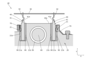
- FIG. 1 is a cross-sectional view illustrating a heat medium heater according to an embodiment of the present invention.
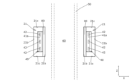
- FIG. 4 is an explanatory diagram showing the layout relationship of each part as viewed in the direction perpendicular to the board.
- the heat medium heater 10 is incorporated into an air conditioning device mounted on a vehicle such as an automobile, heats a heat medium such as coolant (water), and has a heat dissipation structure for the heat generating element 40 that dissipates heat generated by the heat generating element 40, as described below.
- a heat medium such as coolant (water)
- the heat medium heater 10 comprises a housing 20 for arranging various components, a substrate 30 arranged away from the housing 20, a heat generating element 40 mounted on the substrate 30, a heat medium flow path 50 provided within the housing 20, a heater 60 for heating the heat medium flowing through the heat medium flow path 50, a fixing member 70 for fixing the heat generating element 40, an insulating sheet 80 for insulating between the housing 20 and the heat generating element 40, and a heat dissipating filler 90 filled in the pocket 21 of the housing 20.
- the housing 20 is formed from metal or the like, and as shown in FIG. 1, has a pocket 21 that opens on a substrate-facing surface 20a of the housing 20 facing the substrate 30 and is recessed so as to extend toward the side away from the substrate 30.
- This pocket 21 is a portion for arranging a heating element 40, etc., and is formed so as to be open only on the substrate-facing surface 20a side (substrate 30 side) as shown in FIG. 1, and has as its inner walls, as shown in FIGS. 1 and 2, a bottom surface 21a, inner surfaces 21b on both sides in the lateral direction X, and inner surfaces 21c on both sides in the flow path extension direction Z.
- FIGS. 1 As shown in FIGS.
- the pockets 21 are provided on either side of the heat medium flow path 50 in the lateral direction X.
- the pockets 21 are provided on both sides of the heat medium flow path 50 in the lateral direction X (specifically, at positions facing each other in the lateral direction X).
- the above-mentioned horizontal direction X is a direction perpendicular to the substrate vertical direction Y, which is perpendicular to the substrate 30, and the flow path extension direction Z is the direction in which the heat medium flow path 50 extends and is perpendicular to the horizontal direction X and the substrate vertical direction Y.
- the substrate 30 is configured as a rigid type printed circuit board (electronic substrate) and includes printed wiring to which the leads 42 of the heating elements 40 are electrically connected, various electronic components, and the like. As shown in FIG. 1, the substrate 30 is disposed at a position spaced apart from (the substrate-facing surface 20a of) the housing 20 in the substrate vertical direction Y, and is fixed to peripheral members such as the housing 20.
- the heating element 40 is configured as a semiconductor element that is mounted on the substrate 30 and generates heat when energized, and in this embodiment, is configured as an IGBT (Insulated Gate Bipolar Transistor) for controlling the on/off power supply of the heater 60 .
- the heating element 40 has a housing 41 made of synthetic resin or the like, and leads 42 made of metal and provided to protrude from a lead protruding surface 41 a of the housing 41 .
- the leads 42 extend toward the substrate 30 and are electrically connected to an electronic circuit (printed wiring, etc.) of the substrate 30 when inserted into a through hole formed in the substrate 30 .
- a portion of the heating element 40 is placed in each pocket 21 with the lead protruding surface 41 a (leads 42) facing the substrate 30, and with an insulating sheet 80 interposed between the side of the heating element 40 facing the heat medium flow path 50 and the inner surface 21 b of the pocket 21, the heating element 40 is fixed to the housing 20 by being pressed in the lateral direction X toward the heat medium flow path 50 side (the insulating sheet 80 side) by a fixing member 70.
- the heater 60 is configured as a heater that heats a heat medium such as coolant (water) flowing through the heat medium flow path 50, and in this embodiment, as shown in Figures 1 and 2, is arranged on the inner side of the heat medium flow path 50 and extends in the flow path extension direction Z.
- the heater 60 may have any specific form or arrangement as long as it is capable of heating the heat medium flowing through the heat medium flow path 50 .
- the fixing member 70 is for fixing the heating element 40 to the housing 20, and in this embodiment, as shown in FIG. 1 , is composed of a leaf spring installed on the side of the pocket 21 (heating element 40) in the lateral direction X, specifically, on the opposite side of the heat medium flow path 50 across the pocket 21 (heating element 40) in the lateral direction X.
- the specific form and arrangement of the fixing member 70 may be any as long as it is capable of fixing the heating element 40 to the housing 20 .
- the insulating sheet 80 is made of a highly insulating material such as silicon, and as shown in FIG. 1, (at least a portion of) is placed between the housing 20 and the heating element 40 within the pocket 21 to insulate the housing 20 from the heating element 40.
- the insulating sheet 80 also has the function of transmitting heat from the heating element 40 to the housing 20 and dissipating it (radiating heat).
- the heat dissipation filler 90 is filled into the pocket 21 (specifically, the gap between the heating element 40 arranged in the pocket 21 and the inner wall of the pocket 21), and in this embodiment, the heat dissipation filler 90 is configured as a filler such as silicone grease that has fluidity when the pocket 21 is filled with the heat dissipation filler 90 and solidifies a certain time after filling.
- the heat dissipating filler 90 has a function of transferring heat from the heating element 40 to the housing 20 and dissipating it (dissipating heat), and also has a function of insulating between the heating element 40 and the housing 20 .
- the heat dissipating filler 90 is configured as a filler that solidifies a certain time after filling, but the specific form of the heat dissipating filler 90 may be any that is capable of dissipating heat from the heating element 40 to the housing 20, and may be, for example, a filler that remains fluid even after a certain amount of time has passed since filling.
- the heat dissipation structure (heat medium heater 10) of the heat generating element 40 of this embodiment obtained in this manner can achieve the effects described below.
- the housing 20 has an opening at the substrate-facing surface 20a facing the substrate 30, and has a pocket 21 recessed toward the side away from the substrate 30, and the heat generating element 40 is arranged in the pocket 21 with its lead protruding surface 41a facing the substrate 30.
- This allows the heating element 40 to be contained within the pocket 21, simplifying the relationship between the housing 20 and the board 30; and, for example, if the lead protruding surface 41a is arranged facing the horizontal direction X, the leads 42 must be bent approximately 90 degrees toward the board 30 when mounted on the board 30.
- the pocket 21 which is open on the substrate-facing surface 20 a and recessed toward the side away from the substrate 30 , is filled with the heat dissipating filler 90 .
- the pocket 21 is filled with the heat dissipation filler 90 with the substrate facing surface 20a facing upward, so that the pocket 21 receives the heat dissipation filler 90 and prevents the heat dissipation filler 90 from flowing to the surrounding area, thereby ensuring that the heat dissipation filler 90 is positioned in the desired manner and improving the heat dissipation properties of the heat generating element 40.
- the improved heat dissipation performance makes it possible to suppress the temperature rise of each heating element 40, the number of heating elements 40 to be mounted, which is determined in relation to the allowable temperature range, can be reduced, thereby reducing manufacturing costs and improving the design freedom of the surrounding environment by securing space by the amount of the reduced number of mounted elements.
- the structure that improves the heat dissipation properties of the heating element 40 using heat dissipating filler 90 there is no need to provide a complex mechanism for dissipating heat from the heating element 40, which also simplifies the surrounding environment of the heating element 40.
- the heating element 40 is disposed in the pocket 21 provided on the side of the heat transfer medium flow path 50 in the lateral direction X with the lead protruding surface 41 a facing the substrate 30 .
- the distance between the heat medium flow path 50 and the heating element 40 (pocket 21) in the lateral direction X can be easily designed to be narrow, and as a result, the cooling efficiency of the heating element 40 by the heat medium flowing through the heat medium flow path 50 can be improved.
- the pockets 21 in which the heating elements 40 are arranged are provided on both sides of the heat medium flow path 50 in the horizontal direction X, the cooling efficiency of the heating elements 40 by the heat medium flowing through the heat medium flow path 50 can be improved. That is, since the heat medium in the heat medium flow path 50 is gradually heated by the heater 60 extending in the flow path extension direction Z, the temperature of the heat medium located on the upstream side (inlet side) of the heat medium flow path 50 is lower than the temperature of the heat medium located on the downstream side (outlet side) of the heat medium flow path 50.
- a structure is adopted in which the pockets 21 (heat generating elements 40) are disposed on the sides of the heat medium flow path 50 in the lateral direction X, so that both lateral sides of the upstream side (inlet side) of the heat medium flow path 50, where the temperature of the heat medium is low, can be used as installation locations for the heat generating elements 40, thereby improving the cooling efficiency of the heat medium flowing through the heat medium flow path 50 for the heat generating elements 40.
- the heating element 40 is arranged in the pocket 21 with the lead protruding surface 41 a facing the substrate 30, and the fixing member 70 is arranged on the opposite side of the heat medium flow path 50, sandwiching the pocket 21 (heating element 40) in the lateral direction X.
- the fixing member 70 is arranged on the opposite side of the heat medium flow path 50, sandwiching the pocket 21 (heating element 40) in the lateral direction X.
- the heat dissipation structure of the heat generating element 40 is described as being applied to the thermal medium heater 10, but the heat dissipation structure of the heat generating element 40 may also be applied to other devices.
- the heating elements 40 are arranged on both sides of the heat medium flow path 50 in the horizontal direction X, but the specific arrangement of the heating elements 40 (pockets 21) may be any arrangement.
- the heating elements 40 may be arranged on only one side of the heat medium flow path 50 in the horizontal direction X, or multiple heating elements 40 (pockets 21) may be arranged side by side in the flow path extension direction Z.
- the housing 20 is formed as an integrally formed member, but the specific form of the housing 20 is not limited to being formed as an integral part.
- the housing 20 may be formed by forming a portion of the peripheral wall of the pocket 21 that constitutes the pocket 21 separately, and attaching the portion of the housing 20 formed separately to the remaining housing 20.
- heat medium heater 20 housing 20a substrate facing surface 21 pocket 21a bottom surface 21b inner surface 21c inner surface 30 substrate 40 heat generating element 41 housing 41a lead protruding surface 42 lead 50 heat medium flow path 60 heater 70 fixing member 80 insulating sheet 90 heat dissipating filler X lateral direction Y substrate vertical direction Z flow path extension direction
Landscapes
- Cooling Or The Like Of Electrical Apparatus (AREA)
- Cooling Or The Like Of Semiconductors Or Solid State Devices (AREA)
Abstract
【課題】発熱素子周辺の設計自由度を向上する発熱素子の放熱構造および熱媒体ヒータを提供すること。 【解決手段】基板30に実装される発熱素子40を配置する筐体20を備え、筐体20に対して発熱素子40の発熱を放熱させる発熱素子40の放熱構造であって、筐体20は、基板30側に面する基板対向面20aにおいて開口し、基板30から遠ざかる側に向けて凹設されたポケット21を有し、発熱素子40は、そのリード突出面41aを基板30側に向けた状態で、ポケット21内に配置されている発熱素子40の放熱構造。
Description
本発明は、発熱素子の放熱構造および熱媒体ヒータに関する。
従来、基板に実装されるIGBT等の発熱素子を配置する筐体を備え、筐体に対して発熱素子の発熱を放熱させる発熱素子の放熱構造として、特許文献1に開示されるものが公知である。
ところが、特許文献1に開示される発熱素子の放熱構造では、発熱素子周辺の設計自由度について改善の余地がある。
そこで、本発明は、これらの問題点を解決するものであり、簡素な構成で、発熱素子周辺の設計自由度を向上する発熱素子の放熱構造および熱媒体ヒータを提供することを目的とするものである。
本発明の発熱素子の放熱構造は、基板に実装される発熱素子を配置する筐体を備え、前記筐体に対して前記発熱素子の発熱を放熱させる発熱素子の放熱構造であって、前記筐体は、前記基板側に面する基板対向面において開口し、前記基板から遠ざかる側に向けて凹設されたポケットを有し、前記発熱素子は、そのリード突出面を前記基板側に向けた状態で、前記ポケット内に配置されていることにより、前記課題を解決するものである。
本発明の熱媒体ヒータは、前記発熱素子の放熱構造を備えた熱媒体ヒータであって、前記筐体内に設けられた熱媒体流路と、前記熱媒体流路を流れる熱媒体を加熱するためのヒータとを備え、前記ポケットは、前記基板に対して垂直な基板垂直方向に対して直交する横方向において、前記熱媒体流路の側方に設けられていることにより、前記課題を解決するものである。
本発明の熱媒体ヒータは、前記発熱素子の放熱構造を備えた熱媒体ヒータであって、前記筐体内に設けられた熱媒体流路と、前記熱媒体流路を流れる熱媒体を加熱するためのヒータとを備え、前記ポケットは、前記基板に対して垂直な基板垂直方向に対して直交する横方向において、前記熱媒体流路の側方に設けられていることにより、前記課題を解決するものである。
本発明によれば、簡素な構成で、発熱素子周辺の設計自由度を向上することができる。
以下に、本発明の一実施形態に係る熱媒体ヒータ10について、図面に基づいて説明する。
まず、熱媒体ヒータ10は、自動車等の車両に搭載される空調装置に組み込まれ、クーラント(水)等の熱媒体を加熱するものであり、以下に説明する、発熱素子40の発熱を放熱させる発熱素子40の放熱構造を備えるものである。
以下に、熱媒体ヒータ10の具体的構成について、図面に基づいて説明する。
熱媒体ヒータ10は、図1に示すように、各種部品を配置するための筐体20と、筐体20から離して配置される基板30と、基板30に実装される発熱素子40と、筐体20内に設けられた熱媒体流路50と、熱媒体流路50を流れる熱媒体を加熱するためのヒータ60と、発熱素子40を固定するための固定部材70と、筐体20と発熱素子40との間を絶縁する絶縁シート80と、筐体20のポケット21内に充填される放熱充填剤90とを備えている。
筐体20は、金属等から形成され、図1に示すように、基板30側に面する筐体20の基板対向面20aにおいて開口し、基板30から遠ざかる側に向けて延在するように凹設されたポケット21を有している。
このポケット21は、発熱素子40等を配置するための部位であり、図1に示すように、基板対向面20a側(基板30側)のみにおいて開口するように形成され、その内壁として、図1や図2に示すように、底面21aと、横方向Xにおける両側の内側面21bと、流路延在方向Zにおける両側の内側面21cとを有している。
ポケット21は、図1や図2に示すように、横方向Xにおいて熱媒体流路50の側方に設けられており、本実施形態では、横方向Xにおいて熱媒体流路50を挟んだ両側(具体的には、横方向Xに互いに対向する位置)にそれぞれ設けられている。
このポケット21は、発熱素子40等を配置するための部位であり、図1に示すように、基板対向面20a側(基板30側)のみにおいて開口するように形成され、その内壁として、図1や図2に示すように、底面21aと、横方向Xにおける両側の内側面21bと、流路延在方向Zにおける両側の内側面21cとを有している。
ポケット21は、図1や図2に示すように、横方向Xにおいて熱媒体流路50の側方に設けられており、本実施形態では、横方向Xにおいて熱媒体流路50を挟んだ両側(具体的には、横方向Xに互いに対向する位置)にそれぞれ設けられている。
なお、上述した横方向Xは、基板30に対して垂直な基板垂直方向Yに対して直交する方向であり、流路延在方向Zは、熱媒体流路50が延在する方向であり、横方向Xおよび基板垂直方向Yに直交する。
基板30は、リジットタイプのプリント基板(電子基板)として構成され、発熱素子40のリード42が電気的に接続されるプリント配線や各種電子部品等を有している。
基板30は、図1に示すように、基板垂直方向Yにおいて筐体20(の基板対向面20a)から間隔を置いて離れた位置において、筐体20等の周辺部材に対して固定して配置される。
基板30は、図1に示すように、基板垂直方向Yにおいて筐体20(の基板対向面20a)から間隔を置いて離れた位置において、筐体20等の周辺部材に対して固定して配置される。
発熱素子40は、基板30に実装され通電によって発熱を生じる半導体素子として構成され、本実施形態では、ヒータ60の電源オンオフを制御するためのIGBT(Insulated Gate Bipolar Transistor)として構成されている。
発熱素子40は、図1や図2に示すように、合成樹脂等から成るハウジング41と、ハウジング41のリード突出面41aから突出して設けられる金属から成るリード42とを有している。
リード42は、図1に示すように、基板30側に向けて延び、基板30に形成された貫通穴に挿入された状態で、基板30の電子回路(プリント配線等)に電気的に接続される。
発熱素子40は、図1や図2に示すように、合成樹脂等から成るハウジング41と、ハウジング41のリード突出面41aから突出して設けられる金属から成るリード42とを有している。
リード42は、図1に示すように、基板30側に向けて延び、基板30に形成された貫通穴に挿入された状態で、基板30の電子回路(プリント配線等)に電気的に接続される。
発熱素子40は、図1に示すように、リード突出面41a(リード42)を基板30側に向けた状態で各ポケット21内にその一部が配置され、発熱素子40の熱媒体流路50側の側面とポケット21の内側面21bとの間に絶縁シート80を介在させた状態で、固定部材70によって熱媒体流路50側(絶縁シート80側)に向けて横方向Xに押し付けられることで、筐体20に対して固定されている。
なお、ポケット21内に発熱素子40が配置された状態では、図1や図2に示すように、ポケット21の底面21aと発熱素子40との間、ポケット21の各内側面21cと発熱素子40との間、および、ポケット21の内側面21bのうち熱媒体流路50側とは反対側の内側面21bと発熱素子40との間には、間隔が開いており、当該間隔には放熱充填剤90が充填されている。
なお、ポケット21内に発熱素子40が配置された状態では、図1や図2に示すように、ポケット21の底面21aと発熱素子40との間、ポケット21の各内側面21cと発熱素子40との間、および、ポケット21の内側面21bのうち熱媒体流路50側とは反対側の内側面21bと発熱素子40との間には、間隔が開いており、当該間隔には放熱充填剤90が充填されている。
ヒータ60は、熱媒体流路50を流れるクーラント(水)等の熱媒体を加熱するヒータとして構成され、本実施形態では、図1や図2に示すように、熱媒体流路50の内周側に、流路延在方向Zに延在して配置されている。
なお、ヒータ60の具体的態様や配置については、熱媒体流路50を流れる熱媒体を加熱することが可能なものであれば、如何なるものでもよい。
なお、ヒータ60の具体的態様や配置については、熱媒体流路50を流れる熱媒体を加熱することが可能なものであれば、如何なるものでもよい。
固定部材70は、筐体20に対して発熱素子40を固定するためのものであり、本実施形態では、図1に示すように、横方向Xにおけるポケット21(発熱素子40)の側方、具体的には、横方向Xにおいてポケット21(発熱素子40)を挟んで熱媒体流路50の反対側に設置された板バネから構成されている。
なお、固定部材70の具体的態様や配置については、筐体20に対して発熱素子40を固定することが可能なものであれば、如何なるものでもよい。
また、筐体20に対する固定部材70の取り付け態様についても、図1の右側に示した固定部材70のように、ボルト等を用いて筐体20に対して固定部材70を取り付けるものや、図1の左側に示した固定部材70のように、固定部材70によって筐体20の一部を挟み込むことで、筐体20に対して固定部材70を取り付けるもの等、その具体的態様は如何なるものでもよい。
なお、固定部材70の具体的態様や配置については、筐体20に対して発熱素子40を固定することが可能なものであれば、如何なるものでもよい。
また、筐体20に対する固定部材70の取り付け態様についても、図1の右側に示した固定部材70のように、ボルト等を用いて筐体20に対して固定部材70を取り付けるものや、図1の左側に示した固定部材70のように、固定部材70によって筐体20の一部を挟み込むことで、筐体20に対して固定部材70を取り付けるもの等、その具体的態様は如何なるものでもよい。
絶縁シート80は、絶縁性の高いシリコン等から成り、図1に示すように、(その少なくとも一部分が)ポケット21内において筐体20と発熱素子40との間に配置され、筐体20と発熱素子40とを絶縁させるものである。
絶縁シート80は、発熱素子40の熱を筐体20に伝えて逃がす(放熱させる)機能も担っている。
絶縁シート80は、発熱素子40の熱を筐体20に伝えて逃がす(放熱させる)機能も担っている。
放熱充填剤90は、図1に示すように、ポケット21内(具体的には、ポケット21内に配置された発熱素子40とポケット21の内壁との間の隙間)に充填されるものであり、本実施形態では、ポケット21に放熱充填剤90を充填する段階では流動性を有し、充填から一定時間後に固化する、シリコングリス等の充填剤として構成されている。
放熱充填剤90は、発熱素子40の熱を筐体20に伝えて逃がす(放熱させる)機能を担うとともに、発熱素子40と筐体20との間を絶縁させる機能も担う。
なお、本実施形態では、放熱充填剤90が、充填から一定時間後に固化する充填剤として構成されているが、放熱充填剤90の具体的態様については、発熱素子40の熱を筐体20に放熱させることが可能なものであれば、如何なるものでもよく、例えば、充填から時間が経過した後も流動性を有するもの等であってもよい。
放熱充填剤90は、発熱素子40の熱を筐体20に伝えて逃がす(放熱させる)機能を担うとともに、発熱素子40と筐体20との間を絶縁させる機能も担う。
なお、本実施形態では、放熱充填剤90が、充填から一定時間後に固化する充填剤として構成されているが、放熱充填剤90の具体的態様については、発熱素子40の熱を筐体20に放熱させることが可能なものであれば、如何なるものでもよく、例えば、充填から時間が経過した後も流動性を有するもの等であってもよい。
このようにして得られた本実施形態の発熱素子40の放熱構造(熱媒体ヒータ10)では、以下に記載する効果を奏することができる。
(1)すなわち、本実施形態の発熱素子40の放熱構造(熱媒体ヒータ10)では、筐体20が、基板30側に面する基板対向面20aにおいて開口し、基板30から遠ざかる側に向けて凹設されたポケット21を有し、発熱素子40は、そのリード突出面41aを基板30側に向けた状態で、ポケット21内に配置されている。
これにより、ポケット21内に発熱素子40を収容して筐体20と基板30との間を簡素化することができるとともに、例えばリード突出面41aが横方向Xに向いて配置されている場合には、基板30に実装するにあたってリード42を基板30側に向けて約90度折り曲げる必要があるのに対して、本実施形態では、基板30に実装するにあたってリード42が延びる向きを変えるためにリード42を折り曲げる必要が無い(または折り曲げる程度が少なく済む)ため、筐体20の基板対向面20aと基板30との間隔を大きく確保することができる。
そして、筐体20と基板30との間隔を大きく確保することで、基板30の絶縁性を確保し易くなるとともに、筐体20の基板対向面20aと基板30との間の空間を、各種電子部品等を設置するスペースとして利用し易くなる等、発熱素子40の周辺環境の設計自由度を向上させることができ、装置構成をコンパクトに設計することができる。
これにより、ポケット21内に発熱素子40を収容して筐体20と基板30との間を簡素化することができるとともに、例えばリード突出面41aが横方向Xに向いて配置されている場合には、基板30に実装するにあたってリード42を基板30側に向けて約90度折り曲げる必要があるのに対して、本実施形態では、基板30に実装するにあたってリード42が延びる向きを変えるためにリード42を折り曲げる必要が無い(または折り曲げる程度が少なく済む)ため、筐体20の基板対向面20aと基板30との間隔を大きく確保することができる。
そして、筐体20と基板30との間隔を大きく確保することで、基板30の絶縁性を確保し易くなるとともに、筐体20の基板対向面20aと基板30との間の空間を、各種電子部品等を設置するスペースとして利用し易くなる等、発熱素子40の周辺環境の設計自由度を向上させることができ、装置構成をコンパクトに設計することができる。
(2)また、基板対向面20aにおいて開口し基板30から遠ざかる側に向けて凹設されたポケット21内に、放熱充填剤90が充填されている。
これにより、製造時において、発熱素子40を配置したポケット21内に放熱充填剤90を充填する時に、基板対向面20a側を上方に向けた状態でポケット21内に放熱充填剤90を充填することで、ポケット21によって放熱充填剤90を受け止め、放熱充填剤90が周囲に流れてしまうことを防止できるため、放熱充填剤90を所望の態様で確実に配置して、発熱素子40の放熱性を向上させることができる。
また、放熱性の向上によって各発熱素子40の温度上昇を抑制することが可能であるため、温度許容範囲との関係で決定される発熱素子40の実装数を減らすことができ、これにより、製造コストを低減できるとともに、実装数を低減した分だけスペースを確保して周辺環境の設計自由度を向上することができる。
また、放熱充填剤90によって発熱素子40の放熱性を向上させる構造を採用することで、発熱素子40を放熱させるための複雑な機構を設ける必要がないため、この点でも、発熱素子40の周辺環境を簡素化できる。
これにより、製造時において、発熱素子40を配置したポケット21内に放熱充填剤90を充填する時に、基板対向面20a側を上方に向けた状態でポケット21内に放熱充填剤90を充填することで、ポケット21によって放熱充填剤90を受け止め、放熱充填剤90が周囲に流れてしまうことを防止できるため、放熱充填剤90を所望の態様で確実に配置して、発熱素子40の放熱性を向上させることができる。
また、放熱性の向上によって各発熱素子40の温度上昇を抑制することが可能であるため、温度許容範囲との関係で決定される発熱素子40の実装数を減らすことができ、これにより、製造コストを低減できるとともに、実装数を低減した分だけスペースを確保して周辺環境の設計自由度を向上することができる。
また、放熱充填剤90によって発熱素子40の放熱性を向上させる構造を採用することで、発熱素子40を放熱させるための複雑な機構を設ける必要がないため、この点でも、発熱素子40の周辺環境を簡素化できる。
(3)また、横方向Xにおける熱媒体流路50の側方に設けられたポケット21内に、リード突出面41aを基板30側に向けた状態で発熱素子40が配置されている。
これにより、発熱素子40(ポケット21)の横方向位置の設計に特段の制約が無いため、横方向Xにおける熱媒体流路50と発熱素子40(ポケット21)との間隔を容易に狭く設計することができ、その結果、熱媒体流路50を流れる熱媒体による発熱素子40の冷却効率を向上させることができる。
これにより、発熱素子40(ポケット21)の横方向位置の設計に特段の制約が無いため、横方向Xにおける熱媒体流路50と発熱素子40(ポケット21)との間隔を容易に狭く設計することができ、その結果、熱媒体流路50を流れる熱媒体による発熱素子40の冷却効率を向上させることができる。
(4)また、発熱素子40が配置されるポケット21が、横方向Xにおける熱媒体流路50を挟んだ両側にそれぞれ設けられていることにより、熱媒体流路50を流れる熱媒体による発熱素子40の冷却効率を向上させることができる。
すなわち、熱媒体流路50内の熱媒体は、流路延在方向Zに延在するヒータ60による加熱によって徐々に加熱されるため、熱媒体流路50の上流側(入口側)に位置する熱媒体の温度は、熱媒体流路50の下流側(出口側)に位置する熱媒体の温度よりも低い。
そして、本実施形態では、横方向Xにおける熱媒体流路50の側方にポケット21(発熱素子40)を配置する構造を採用することにより、熱媒体の温度が低い熱媒体流路50の上流側(入口側)の横方向両側を発熱素子40の設置場所として利用することが可能であるため、熱媒体流路50を流れる熱媒体による発熱素子40の冷却効率を向上させることができる。
すなわち、熱媒体流路50内の熱媒体は、流路延在方向Zに延在するヒータ60による加熱によって徐々に加熱されるため、熱媒体流路50の上流側(入口側)に位置する熱媒体の温度は、熱媒体流路50の下流側(出口側)に位置する熱媒体の温度よりも低い。
そして、本実施形態では、横方向Xにおける熱媒体流路50の側方にポケット21(発熱素子40)を配置する構造を採用することにより、熱媒体の温度が低い熱媒体流路50の上流側(入口側)の横方向両側を発熱素子40の設置場所として利用することが可能であるため、熱媒体流路50を流れる熱媒体による発熱素子40の冷却効率を向上させることができる。
(5)また、発熱素子40が、リード突出面41aを基板30側に向けた状態でポケット21内に配置されるとともに、固定部材70が、横方向Xにおいてポケット21(発熱素子40)を挟んで熱媒体流路50の反対側に配置されている。
これにより、発熱素子40のリード42と固定部材70との間の干渉に配慮する必要が無い(または必要性が低い)ため、固定部材70に関する設計自由度を確保でき、また、固定部材70を発熱素子40の横方向Xにおける側方に配置することで、固定部材70が基板30の絶縁性を阻害する要因になることを回避できる。
これにより、発熱素子40のリード42と固定部材70との間の干渉に配慮する必要が無い(または必要性が低い)ため、固定部材70に関する設計自由度を確保でき、また、固定部材70を発熱素子40の横方向Xにおける側方に配置することで、固定部材70が基板30の絶縁性を阻害する要因になることを回避できる。
以上、本発明の実施形態を詳述したが、本発明は上記実施形態に限定されるものではなく、上記または下記の実施形態や変形例の各構成を任意に組み合わせて、熱媒体ヒータ10や発熱素子40の放熱構造を構成する等、特許請求の範囲に記載された本発明を逸脱することなく種々の設計変更を行なうことが可能である。
例えば、上述した実施形態では、発熱素子40の放熱構造が、熱媒体ヒータ10に適用されるものとして説明したが、発熱素子40の放熱構造を他の装置機器に適用してもよい。
また、上述した実施形態では、横方向Xにおける熱媒体流路50を挟んだ両側に、それぞれ発熱素子40(ポケット21)が配置されるものとして説明したが、発熱素子40(ポケット21)の具体的配置については、如何なるものでもよく、例えば、横方向Xにおける熱媒体流路50を挟んだ両側のうち片側のみに、発熱素子40(ポケット21)を配置してもよく、また、流路延在方向Zにおいて、複数の発熱素子40(ポケット21)を並べて配置してもよい。
また、上述した実施形態では、筐体20が一体に形成された部材として形成されているが、筐体20の具体的態様については、一体に形成されたものに限定されず、例えば、ポケット21を構成するポケット21の周辺壁のうちの一部を別体に形成し、当該別体に形成された筐体20の一部を、残りの筐体20に取り付けることで、筐体20を構成してもよい。
10 ・・・ 熱媒体ヒータ
20 ・・・ 筐体
20a ・・・ 基板対向面
21 ・・・ ポケット
21a ・・・ 底面
21b ・・・ 内側面
21c ・・・ 内側面
30 ・・・ 基板
40 ・・・ 発熱素子
41 ・・・ ハウジング
41a ・・・ リード突出面
42 ・・・ リード
50 ・・・ 熱媒体流路
60 ・・・ ヒータ
70 ・・・ 固定部材
80 ・・・ 絶縁シート
90 ・・・ 放熱充填剤
X ・・・ 横方向
Y ・・・ 基板垂直方向
Z ・・・ 流路延在方向
20 ・・・ 筐体
20a ・・・ 基板対向面
21 ・・・ ポケット
21a ・・・ 底面
21b ・・・ 内側面
21c ・・・ 内側面
30 ・・・ 基板
40 ・・・ 発熱素子
41 ・・・ ハウジング
41a ・・・ リード突出面
42 ・・・ リード
50 ・・・ 熱媒体流路
60 ・・・ ヒータ
70 ・・・ 固定部材
80 ・・・ 絶縁シート
90 ・・・ 放熱充填剤
X ・・・ 横方向
Y ・・・ 基板垂直方向
Z ・・・ 流路延在方向
Claims (5)
- 基板に実装される発熱素子を配置する筐体を備え、前記筐体に対して前記発熱素子の発熱を放熱させる発熱素子の放熱構造であって、
前記筐体は、前記基板側に面する基板対向面において開口し、前記基板から遠ざかる側に向けて凹設されたポケットを有し、
前記発熱素子は、そのリード突出面を前記基板側に向けた状態で、前記ポケット内に配置されていることを特徴とする発熱素子の放熱構造。 - 前記ポケット内には、放熱充填剤が充填されていることを特徴とする請求項1に記載の発熱素子の放熱構造。
- 請求項1に記載の発熱素子の放熱構造を備えた熱媒体ヒータであって、
前記筐体内に設けられた熱媒体流路と、前記熱媒体流路を流れる熱媒体を加熱するためのヒータとを備え、
前記ポケットは、前記基板に対して垂直な基板垂直方向に対して直交する横方向において、前記熱媒体流路の側方に設けられていることを特徴とする熱媒体ヒータ。 - 前記ポケットは、前記横方向における前記熱媒体流路を挟んだ両側にそれぞれ設けられ、
前記各ポケットに、前記発熱素子がそれぞれ配置されていることを特徴とする請求項3に記載の熱媒体ヒータ。 - 前記筐体に対して前記発熱素子を固定するための固定部材を更に備え、
前記固定部材は、前記横方向において前記ポケットを挟んで前記熱媒体流路の反対側に配置されていることを特徴とする請求項3に記載の熱媒体ヒータ。
Priority Applications (1)
| Application Number | Priority Date | Filing Date | Title |
|---|---|---|---|
| CN202480019736.5A CN120917569A (zh) | 2023-06-15 | 2024-06-13 | 发热元件的散热结构和热介质加热器 |
Applications Claiming Priority (2)
| Application Number | Priority Date | Filing Date | Title |
|---|---|---|---|
| JP2023-098221 | 2023-06-15 | ||
| JP2023098221A JP2024179399A (ja) | 2023-06-15 | 2023-06-15 | 発熱素子の放熱構造および熱媒体ヒータ |
Publications (1)
| Publication Number | Publication Date |
|---|---|
| WO2024257819A1 true WO2024257819A1 (ja) | 2024-12-19 |
Family
ID=93852189
Family Applications (1)
| Application Number | Title | Priority Date | Filing Date |
|---|---|---|---|
| PCT/JP2024/021434 Ceased WO2024257819A1 (ja) | 2023-06-15 | 2024-06-13 | 発熱素子の放熱構造および熱媒体ヒータ |
Country Status (3)
| Country | Link |
|---|---|
| JP (1) | JP2024179399A (ja) |
| CN (1) | CN120917569A (ja) |
| WO (1) | WO2024257819A1 (ja) |
Citations (5)
| Publication number | Priority date | Publication date | Assignee | Title |
|---|---|---|---|---|
| JPH1093271A (ja) * | 1996-09-11 | 1998-04-10 | Oki Electric Ind Co Ltd | パワーデバイスパッケージの放熱及び固定方法 |
| JP2000091485A (ja) * | 1998-07-14 | 2000-03-31 | Denso Corp | 半導体装置 |
| WO2013080317A1 (ja) * | 2011-11-30 | 2013-06-06 | 三菱電機株式会社 | 半導体装置、及び車載用電力変換装置 |
| JP2013177028A (ja) * | 2012-02-28 | 2013-09-09 | Mitsubishi Heavy Ind Ltd | 熱媒体加熱装置 |
| JP2023076932A (ja) * | 2021-11-24 | 2023-06-05 | サンデン株式会社 | 熱媒体加熱装置 |
-
2023
- 2023-06-15 JP JP2023098221A patent/JP2024179399A/ja active Pending
-
2024
- 2024-06-13 WO PCT/JP2024/021434 patent/WO2024257819A1/ja not_active Ceased
- 2024-06-13 CN CN202480019736.5A patent/CN120917569A/zh active Pending
Patent Citations (5)
| Publication number | Priority date | Publication date | Assignee | Title |
|---|---|---|---|---|
| JPH1093271A (ja) * | 1996-09-11 | 1998-04-10 | Oki Electric Ind Co Ltd | パワーデバイスパッケージの放熱及び固定方法 |
| JP2000091485A (ja) * | 1998-07-14 | 2000-03-31 | Denso Corp | 半導体装置 |
| WO2013080317A1 (ja) * | 2011-11-30 | 2013-06-06 | 三菱電機株式会社 | 半導体装置、及び車載用電力変換装置 |
| JP2013177028A (ja) * | 2012-02-28 | 2013-09-09 | Mitsubishi Heavy Ind Ltd | 熱媒体加熱装置 |
| JP2023076932A (ja) * | 2021-11-24 | 2023-06-05 | サンデン株式会社 | 熱媒体加熱装置 |
Also Published As
| Publication number | Publication date |
|---|---|
| CN120917569A (zh) | 2025-11-07 |
| JP2024179399A (ja) | 2024-12-26 |
Similar Documents
| Publication | Publication Date | Title |
|---|---|---|
| US8948582B2 (en) | Heat medium heating device and vehicle air conditioner including the same | |
| CN101663511B (zh) | 自动变速器用控制单元冷却装置 | |
| JP5024600B2 (ja) | 発熱体冷却構造及びその構造を備えた駆動装置 | |
| JP5979892B2 (ja) | 熱媒体加熱装置およびそれを備えた車両用空調装置 | |
| CN102007672B (zh) | 电机上的变频器 | |
| US20140050465A1 (en) | Heat medium heating device and vehicular air-conditioning device including the same | |
| JPH07283564A (ja) | 電子装置 | |
| JP6675937B2 (ja) | 熱媒体加熱装置およびこれを用いた車両用空調装置 | |
| CN104509229B (zh) | 散热板 | |
| CN203896645U (zh) | 伺服放大器 | |
| KR20150011635A (ko) | 차량용 공조장치 | |
| JP2013220707A (ja) | 熱媒体加熱装置およびそれを備えた車両用空調装置 | |
| JP2024179399A (ja) | 発熱素子の放熱構造および熱媒体ヒータ | |
| CN220274110U (zh) | 一种散热结构以及伺服驱动器 | |
| CN117119744A (zh) | 一种散热结构以及伺服驱动器 | |
| JP2022022027A (ja) | 電子制御装置および電子制御装置の集合体 | |
| CN101151585A (zh) | 冷却装置 | |
| JP4403753B2 (ja) | 電力変換装置 | |
| JP2013177028A (ja) | 熱媒体加熱装置 | |
| CN104054252B (zh) | 功率转换装置 | |
| JP2011228430A (ja) | 半導体モジュール冷却装置 | |
| JP2013220706A (ja) | 熱媒体加熱装置およびそれを備えた車両用空調装置 | |
| JP2005150539A (ja) | 電子機器 | |
| CN220674183U (zh) | 散热盒及其电气设备 | |
| KR20140082353A (ko) | 내장형 컴퓨터 전자제어장치의 냉각 장치 |
Legal Events
| Date | Code | Title | Description |
|---|---|---|---|
| 121 | Ep: the epo has been informed by wipo that ep was designated in this application |
Ref document number: 24823434 Country of ref document: EP Kind code of ref document: A1 |
|
| WWE | Wipo information: entry into national phase |
Ref document number: 202480019736.5 Country of ref document: CN |
|
| WWP | Wipo information: published in national office |
Ref document number: 202480019736.5 Country of ref document: CN |
|
| NENP | Non-entry into the national phase |
Ref country code: DE |