WO2024257757A1 - 配線モジュール - Google Patents
配線モジュール Download PDFInfo
- Publication number
- WO2024257757A1 WO2024257757A1 PCT/JP2024/021178 JP2024021178W WO2024257757A1 WO 2024257757 A1 WO2024257757 A1 WO 2024257757A1 JP 2024021178 W JP2024021178 W JP 2024021178W WO 2024257757 A1 WO2024257757 A1 WO 2024257757A1
- Authority
- WO
- WIPO (PCT)
- Prior art keywords
- wiring
- electrode
- connection portion
- electrode connection
- wiring material
- Prior art date
- Legal status (The legal status is an assumption and is not a legal conclusion. Google has not performed a legal analysis and makes no representation as to the accuracy of the status listed.)
- Pending
Links
Images


Classifications
-
- H—ELECTRICITY
- H01—ELECTRIC ELEMENTS
- H01G—CAPACITORS; CAPACITORS, RECTIFIERS, DETECTORS, SWITCHING DEVICES, LIGHT-SENSITIVE OR TEMPERATURE-SENSITIVE DEVICES OF THE ELECTROLYTIC TYPE
- H01G4/00—Fixed capacitors; Processes of their manufacture
- H01G4/002—Details
- H01G4/228—Terminals
-
- H—ELECTRICITY
- H01—ELECTRIC ELEMENTS
- H01M—PROCESSES OR MEANS, e.g. BATTERIES, FOR THE DIRECT CONVERSION OF CHEMICAL ENERGY INTO ELECTRICAL ENERGY
- H01M50/00—Constructional details or processes of manufacture of the non-active parts of electrochemical cells other than fuel cells, e.g. hybrid cells
- H01M50/50—Current conducting connections for cells or batteries
- H01M50/502—Interconnectors for connecting terminals of adjacent batteries; Interconnectors for connecting cells outside a battery casing
- H01M50/503—Interconnectors for connecting terminals of adjacent batteries; Interconnectors for connecting cells outside a battery casing characterised by the shape of the interconnectors
-
- H—ELECTRICITY
- H01—ELECTRIC ELEMENTS
- H01M—PROCESSES OR MEANS, e.g. BATTERIES, FOR THE DIRECT CONVERSION OF CHEMICAL ENERGY INTO ELECTRICAL ENERGY
- H01M50/00—Constructional details or processes of manufacture of the non-active parts of electrochemical cells other than fuel cells, e.g. hybrid cells
- H01M50/50—Current conducting connections for cells or batteries
- H01M50/502—Interconnectors for connecting terminals of adjacent batteries; Interconnectors for connecting cells outside a battery casing
- H01M50/521—Interconnectors for connecting terminals of adjacent batteries; Interconnectors for connecting cells outside a battery casing characterised by the material
- H01M50/526—Interconnectors for connecting terminals of adjacent batteries; Interconnectors for connecting cells outside a battery casing characterised by the material having a layered structure
-
- Y—GENERAL TAGGING OF NEW TECHNOLOGICAL DEVELOPMENTS; GENERAL TAGGING OF CROSS-SECTIONAL TECHNOLOGIES SPANNING OVER SEVERAL SECTIONS OF THE IPC; TECHNICAL SUBJECTS COVERED BY FORMER USPC CROSS-REFERENCE ART COLLECTIONS [XRACs] AND DIGESTS
- Y02—TECHNOLOGIES OR APPLICATIONS FOR MITIGATION OR ADAPTATION AGAINST CLIMATE CHANGE
- Y02E—REDUCTION OF GREENHOUSE GAS [GHG] EMISSIONS, RELATED TO ENERGY GENERATION, TRANSMISSION OR DISTRIBUTION
- Y02E60/00—Enabling technologies; Technologies with a potential or indirect contribution to GHG emissions mitigation
- Y02E60/10—Energy storage using batteries
Definitions
- This disclosure relates to a wiring module.
- a busbar described in JP 2023-47446 A (Patent Document 1 below) is known.
- the busbar in Patent Document 1 has two connection parts and an intermediate part that connects the two connection parts.
- the connection parts are connected to the electrode terminals of the energy storage element.
- the intermediate part has a mountain shape that protrudes upward from the connection parts.
- the intermediate part can absorb misalignment between the two connection parts.
- the busbar is made up of multiple plate-shaped base materials stacked in the vertical direction. This allows the intermediate part to be formed more flexibly compared to when the busbar is made up of a single metal plate.
- Patent Document 2 Japanese Patent Application Laid-Open No. 2019-207825 (Patent Document 2 below) describes a wiring module that includes a connection bus bar that is connected to an electrode terminal, and a voltage detection wire.
- This connection bus bar has a bent portion that protrudes in a direction away from the electrode terminal (upward).
- the voltage detection wire is connected to a portion of the connection bus bar that is connected to the electrode terminal (a portion different from the bent portion) via a voltage detection terminal.
- connection portion has a certain strength for the connection process with the electrode terminal, but since the busbar in Patent Document 1 is constructed by stacking multiple base materials, there is a risk that the strength of the connection portion will be reduced.
- the wiring module disclosed herein is a wiring module that is attached to a plurality of energy storage elements having electrode terminals, and includes a bus bar and wiring material, the bus bar includes an electrode connection portion that is connected to the electrode terminals, and a lamination portion that is configured by laminating a plurality of plate-shaped base materials and connects two adjacent electrode connection portions, and the lamination portion includes a wiring material connection portion that is electrically connected to the wiring material.
- This disclosure makes it possible to provide a wiring module that has excellent connection reliability between the busbar and the electrode terminal, and between the busbar and the wiring material.
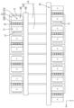
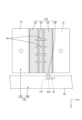
- FIG. 1 is a plan view of the electricity storage module according to the first embodiment.
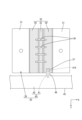
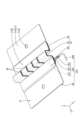
- FIG. 2 is an enlarged perspective view of the wiring module according to the first embodiment.
- FIG. 3 is an enlarged bottom view of the wiring module according to the first embodiment.
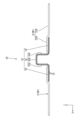
- FIG. 4 is a plan view of the bus bar according to the first embodiment.
- FIG. 5 is a side view of the bus bar according to the first embodiment.
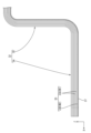
- FIG. 6 is an enlarged side view of a laminated portion of the bus bar shown in FIG.
- FIG. 7 is an enlarged perspective view of the wiring module according to the second embodiment.
- FIG. 8 is an enlarged bottom view of the wiring module according to the second embodiment.
- FIG. 9 is an enlarged perspective view of a wiring module according to another embodiment.
- the wiring module disclosed herein is a wiring module attached to a plurality of energy storage elements having electrode terminals, and includes a bus bar and wiring material.
- the bus bar includes an electrode connection portion connected to the electrode terminals, and a lamination portion configured by stacking a plurality of plate-shaped base materials and connecting two adjacent electrode connection portions, and the lamination portion includes a wiring material connection portion electrically connected to the wiring material.
- the electrode connection part can be formed separately from the laminated part having a configuration in which multiple base materials are laminated, thereby improving the strength of the electrode connection part. This makes it easier to electrically connect the electrode connection part to the electrode terminal.
- the busbar and the wiring material can be electrically connected by the wiring material connection portion provided in the laminated portion. Also, since there is no need to provide a wiring material connection portion at the electrode connection portion, it is easier to ensure electrical connection between the electrode connection portion and the electrode terminal, for example, even if the busbar is made smaller.
- the laminated portion includes an overlapping portion that overlaps with the electrode connection portion and is connected to the electrode connection portion, and that the overlapping portion includes the wiring material connection portion.
- the wiring material connection portion is formed in the overlapping portion of the laminate that is connected to the electrode connection portion.
- the overlapping portion is a portion of the laminate that has low flexibility because it is configured to overlap the electrode connection portion and connect to the electrode connection portion. Therefore, by providing the wiring material connection portion in the overlapping portion, it is possible to prevent the flexibility of the portion of the laminate that is not overlapped with the electrode connection portion from being impaired and to prevent stress from being applied to the connection portion between the wiring material connection portion and the wiring material.
- the electrode connection portion is made of a first metal
- the plurality of substrates include at least one first substrate made of the first metal and at least one second substrate made of a second metal different from the first metal
- the wiring material includes a conductor portion made of the second metal
- the electrode connection portion is connected to the first substrate
- the wiring material connection portion is formed of a second substrate and connected to the conductor portion.
- connection between the electrode connection portion and the laminated portion, and the connection between the wiring material connection portion and the wiring material are made between metals of the same type. This makes these connections easier.
- the laminated portion preferably includes an extension portion that extends outward from the electrode connection portions in a third direction perpendicular to both a first direction in which the electrode connection portions are arranged and a second direction in which the electrode connection portions and the electrode terminals face each other, and the extension portion preferably includes the wiring material connection portion.
- the wiring material and the wiring material connection portion can be connected even when the wiring material is extended in the first direction.
- facing in this specification refers to surfaces or components facing each other, and includes not only cases where they are completely facing each other, but also cases where they are partially facing each other.
- facing in this specification includes both cases where there is a component separate from the two parts between the two parts, and cases where there is nothing between the two parts.
- An energy storage module 10 including a wiring module 20 of the present embodiment is mounted on a vehicle as a power source for driving the vehicle, such as an electric vehicle or a hybrid vehicle.
- the direction indicated by the arrow Z is the upward direction
- the direction indicated by the arrow X is the forward direction
- the direction indicated by the arrow Y is the leftward direction. Note that, for multiple identical members, only some of the members may be labeled with a reference symbol, and the reference symbols for the other members may be omitted.
- the energy storage module 10 comprises a number of energy storage elements 11 arranged in a row, and a wiring module 20 attached to the upper surfaces of the plurality of energy storage elements 11.
- the wiring module 20 is attached to both ends in the left-right direction of the plurality of energy storage elements 11.
- the energy storage elements 11 are in the form of a flattened rectangular parallelepiped with energy storage elements housed inside.
- the energy storage element 11 has two electrode terminals 12 at both ends in the left-right direction of the upper surface. One of the two electrode terminals 12 is a positive electrode, and the other is a negative electrode.
- the electrode terminals 12 are electrically connected to a bus bar 30.
- the wiring module 20 includes a bus bar 30 and wiring members 40 connected to the bus bar 30 .
- the bus bar 30 has a rectangular shape in a plan view.
- the bus bar 30 includes two electrode connection parts 31 and a laminated part 32 that connects the two adjacent electrode connection parts 31.
- the two electrode connection parts 31 are arranged side by side in the front-rear direction.
- the electrode connection parts 31 are formed by bending a single metal plate.
- the electrode connection parts 31 are made of a first metal M1.
- the first metal M1 is, for example, aluminum or an aluminum alloy.
- the electrode connection parts 31 include a main body part 31A and an extension part 31B that extends from the main body part 31A.
- the electrode connection parts 31 have a through hole 31C that penetrates the main body part 31A in the up-down direction.
- the main body portion 31A is disposed so as to face the electrode terminal 12 in the vertical direction, and is connected to the electrode terminal 12, for example, by welding.
- the electrode terminal 12 is made of a first metal M1. Since the electrode terminal 12 and the main body portion 31A are made of the same metal, electrical connection between the electrode terminal 12 and the main body portion 31A is facilitated. In addition, electrolytic corrosion is prevented at the connection portion between the electrode terminal 12 and the main body portion 31A.
- the through hole 31C engages with a protrusion (not shown) protruding from the electrode terminal 12. This positions the bus bar 30 and the electrode terminal 12.
- the laminated portion 32 is configured by laminating a plurality of plate-shaped base materials 33.
- the base materials 33 are, for example, thin metal plates or metal foils.
- the members 33 are connected to each other by, for example, welding or brazing.
- the plurality of base members 33 are formed of a plurality of (specifically, seven) first base members 33A.
- the first substrate 33A is made of a first metal M1.
- the second substrate 33B is made of a second metal M2 different from the first metal M1.
- the second metal M2 is, for example, copper or a copper alloy.
- the laminated portion 32 includes two overlapping portions 34 overlapping the extension portion 31B, and a main body portion 35 disposed between the two overlapping portions 34.
- the overlapping portions 34 are overlapped under the extension portion 31B.
- the upper surface of the overlapping portion 34 is connected to the extension portion 31B, for example, by welding.
- the first base material 33A and the second base material 33B are stacked in the vertical direction, and the second base material 33B is disposed at the lowest position among the multiple base materials 33.
- the multiple first base materials 33A are disposed above the single second base material 33B.
- the upper surface of the overlapping portion 34 is constituted by the first base material 33A and is constituted by the first metal M1. Since the extension portion 31B is also constituted by the first metal M1, it is easy to electrically connect the upper surface of the overlapping portion 34 and the extension portion 31B. Furthermore, electrolytic corrosion is prevented at the connection portion between the overlapping portion 34 and the extension portion 31B.
- the main body 35 is formed in a mountain shape that protrudes upward from the overlapping portion 34.
- the main body 35 has two side portions 35A that rise from the overlapping portion 34, and a ceiling portion 35B that connects the upper ends of the two side portions 35A.
- the main body 35 is made elastically deformable, and it is tolerable to a certain extent that the two electrode connection portions 31 are displaced from each other in the front-to-back and up-down directions. Therefore, it is possible to absorb assembly tolerances between the electrode connection portions 31 and the electrode terminals 12, etc. It is also possible to tolerate expansion and contraction of the storage element 11 due to temperature changes.
- the laminated portion 32 has a number of slits 36 formed therein, penetrating the main body portion 35 and the portion of the overlapping portion 34 closer to the main body portion 35.
- Each slit 36 extends in the front-to-rear direction.
- one of the two overlapping portions 34 included in the laminated portion 32 includes a wiring member connection portion 37.
- the wiring member connection portion 37 is a portion of the busbar 30 that is electrically connected to the wiring members 40 described below.
- the wiring member connection portion 37 is disposed in the overlapping portion 34 disposed on the front side.
- the wiring member connection portion 37 is located on the lower surface of the overlapping portion 34.
- the substrate 33 disposed on the lowermost side is the second substrate 33B (see FIG. 6).
- the wiring member connection portion 37 is part of the second substrate 33B, and is formed from the second metal M2.
- the wiring material 40 includes a conductor portion 41 and a support member 42 that supports the conductor portion 41.
- the wiring material 40 is a flexible printed circuit board.
- the support member 42 is made of an insulating synthetic resin and includes a base film and a coverlay film.
- the conductor portion 41 is made of a second metal M2.
- the conductor portion 41 has a thin wire shape.
- a land portion 41A is formed at an end of the conductor portion 41.
- the land portion 41A is wider than the other portions of the conductor portion 41.
- the conductor portion 41 is formed on the base film and is covered from above by a coverlay film. An opening that exposes the land portion 41A upward is formed in the coverlay film.
- the wiring material 40 comprises a main body portion 43 extending in the front-rear direction, and a connection piece 44 extending in the left-right direction from the main body portion 43.
- a land portion 41A is arranged on the connection piece 44.
- the connection piece 44 is overlapped under the wiring material connection portion 37 of the overlapping portion 34.
- the land portion 41A and the wiring material connection portion 37 are connected by, for example, soldering.
- the land portion 41A and the wiring material connection portion 37 are made of the second metal M2, which facilitates electrical connection between the land portion 41A and the wiring material connection portion 37.
- the end of the conductor portion 41 opposite the land portion 41A is connected to a connector (not shown).
- This connector is adapted to be connected to an external ECU (Electronic Control Unit) or the like.
- the ECU is equipped with a microcomputer, elements, etc., and is of a well-known configuration with functions such as detecting the voltage, current, temperature, etc. of each storage element 11 and controlling the charging and discharging of each storage element 11.
- the conductor portion 41 functions as a voltage detection line.
- the overlapping portion 34 of the laminated portion 32 is connected to the electrode connection portion 31 and is not easily deformed.
- the main body portion 35 of the laminated portion 32 is elastically deformable and has flexibility. Unlike this embodiment, if a wiring member connection portion is provided on the main body portion, the flexibility of the main body portion may be impaired by connection to the wiring member. In addition, there is a risk that stress will be applied to the connection portion between the wiring member connection portion and the wiring member when the main body portion deforms.
- the wiring member connection portion 37 is provided on the overlapping portion 34 rather than on the main body portion 35. This makes it possible to maintain the reliability of the connection between the busbar 30 and the wiring member 40 without impairing the flexibility of the main body portion 35.
- the wiring module 20 in embodiment 1 is a wiring module 20 that is attached to a plurality of energy storage elements 11 having electrode terminals 12, and includes a bus bar 30 and wiring material 40.
- the bus bar 30 includes an electrode connection portion 31 that is connected to the electrode terminal 12, and a laminate portion 32 that is configured by stacking a plurality of plate-shaped base materials 33 and connects two adjacent electrode connection portions 31.
- the laminate portion 32 includes a wiring material connection portion 37 that is electrically connected to the wiring material 40.
- the electrode connection portion 31 can be formed separately from the laminate portion 32, which is configured by laminating multiple base materials 33, and the strength of the electrode connection portion 31 can be improved. This makes it easier to electrically connect the electrode connection portion 31 to the electrode terminal 12.
- the busbar 30 and the wiring material 40 can be electrically connected by the wiring material connection portion 37 provided in the laminated portion 32.
- the wiring material connection portion 37 in the electrode connection portion 31 since it is not necessary to provide the wiring material connection portion 37 in the electrode connection portion 31, it is easier to ensure electrical connection between the electrode connection portion 31 and the electrode terminal 12 even when the busbar 30 is miniaturized, for example.
- the laminated portion 32 includes an overlapping portion 34 that overlaps with the electrode connection portion 31 and is connected to the electrode connection portion 31, and the overlapping portion 34 includes a wiring material connection portion 37.
- the wiring member connection portion 37 is formed in the overlapping portion 34 of the laminated portion 32, which is connected to the electrode connection portion 31.
- the overlapping portion 34 is a portion of the laminated portion 32 that has low flexibility because it is configured to overlap the electrode connection portion 31 and connect to the electrode connection portion 31. Therefore, by providing the wiring member connection portion 37 in the overlapping portion 34, it is possible to prevent the flexibility of the portion of the laminated portion 32 that is not overlapped with the electrode connection portion 31 from being impaired and to prevent stress from being applied to the connection portion between the wiring member connection portion 37 and the wiring member 40.
- the electrode connection portion 31 is made of a first metal M1
- the multiple substrates 33 include at least one first substrate 33A made of the first metal M1 and at least one second substrate 33B made of a second metal M2 different from the first metal M1
- the wiring material 40 includes a conductor portion 41 made of the second metal M2
- the electrode connection portion 31 is connected to the first substrate 33A
- the wiring material connection portion 37 is formed of the second substrate 33B and is connected to the conductor portion 41.
- the connection between the electrode terminal 12 and the electrode connection portion 31, the connection between the electrode connection portion 31 and the laminate portion 32, and the connection between the wiring member connection portion 37 and the wiring member 40 are connections between metals of the same kind. This makes these connections easier.
- the wiring module 120 includes a bus bar 130 and wiring material 140.
- the front-rear direction is an example of the first direction.
- the up-down direction is an example of the second direction.
- the left-right direction is an example of the third direction.
- the same components as those in the first embodiment may be given the same reference numerals as those in the first embodiment, and descriptions thereof may be omitted. Furthermore, descriptions of the effects that overlap with those in the first embodiment will be omitted.
- the busbar 130 comprises two electrode connection portions 31 and a laminated portion 132.
- the laminated portion 132 comprises a plurality of first substrates 33A and one second substrate 33B that is laminated on the lower side of the plurality of first substrates 33A (see FIG. 6).
- the laminated portion 132 has an extension portion 138 that extends to the left of the electrode connection portion 31 in the width direction (left-right direction) of the busbar 30.
- the extension portion 138 is composed only of the second substrate 33B.
- the extension portion 138 has a wiring material connection portion 137 on its underside.
- the wiring material 140 does not have the connection piece 44 of embodiment 1, but only has a main body portion 43 extending in the front-rear direction. That is, the wiring material 140 is in a state of extending in the front-rear direction in the wiring module 120. As shown in FIG. 8, a land portion 41A is formed in the main body portion 43. An extension portion 138 is disposed on the land portion 41A, and the land portion 41A and the wiring material connection portion 137 are connected by soldering or the like.
- connection portion between the busbar 130 and the wiring material 140 is formed by the extension portion 138 instead of the connection piece 44 of embodiment 1.
- the wiring material 140 can be made into a simple strip shape, making it easier to form the wiring material 140.
- the extension portion 138 is made of the base material 33, and is easier to increase in strength compared to the connection piece 44. This improves the connection reliability between the busbar 130 and the wiring material 140.
- the laminated portion 132 has an extension portion 138 that extends outward from the electrode connection portions 31 in a third direction (left-right direction) that is perpendicular to both the first direction (front-to-back direction) in which the electrode connection portions 31 are arranged and the second direction (up-down direction) in which the electrode connection portions 31 and the electrode terminals 12 face each other, and the extension portion 138 has a wiring material connection portion 137.
- the wiring material 140 and the wiring material connection portion 137 can be connected even when the wiring material 140 is extended in the first direction.
- the busbars 30 and 130 are made of the first metal M1 and the second metal M2, but the busbars may be made of a single type of metal.
- the multiple substrates 33 include multiple first substrates 33A and one second substrate 33B, but the number of first substrates and second substrates included in the multiple substrates can be changed as appropriate.
- the multiple substrates may all be made of one type of metal.
- the laminated portion 32, 132 and the electrode connection portion 31 are connected by welding, but the laminated portion and the electrode connection portion may be electrically connected by being mechanically compressed and fixed.
- the laminated portion 32, 132 has a main body portion 35 that protrudes from the overlapping portion 34, but the main body portion 35 may be flat and substantially flush with the overlapping portion 34.
- slits 36 are formed in the laminated portions 32 and 132, but slits do not have to be provided.
- the wiring connection portion 37 is provided in the overlapping portion 34.
- the wiring connection portion may be provided in the main body portion.
- the extending portion 138 may extend from the main body portion 35, not limited to the overlapping portion 34, as long as the extending portion 138 extends outward from the electrode connection portion 31 in the third direction.
- the extending portion 138 may be formed from any of the base materials 33 constituting the laminate portion 33.
- the wiring material 40, 140 is a flexible printed circuit board, but the wiring material may be, for example, an electric wire or a flexible flat cable (FFC).
- the wiring material may also be electrically connected to the bus bar via a terminal, a small metal piece, or the like.
- the wiring module of the present disclosure includes a wiring module 220 shown in FIG. 9.
- the wiring module 220 includes a bus bar 30, a wiring material 240, and a terminal 250.
- the wiring material 240 is an electric wire.
- the terminal 250 includes a terminal body 251 welded to the bus bar 30, a core wire crimping portion 252 crimped to the core wire of the electric wire, and an insulating coating crimping portion 253 crimped to the insulating coating of the electric wire.
Landscapes
- Chemical & Material Sciences (AREA)
- Chemical Kinetics & Catalysis (AREA)
- Electrochemistry (AREA)
- General Chemical & Material Sciences (AREA)
- Engineering & Computer Science (AREA)
- Power Engineering (AREA)
- Manufacturing & Machinery (AREA)
- Microelectronics & Electronic Packaging (AREA)
- Connection Of Batteries Or Terminals (AREA)
Applications Claiming Priority (2)
| Application Number | Priority Date | Filing Date | Title |
|---|---|---|---|
| JP2023-097456 | 2023-06-14 | ||
| JP2023097456A JP2024178990A (ja) | 2023-06-14 | 2023-06-14 | 配線モジュール |
Publications (1)
| Publication Number | Publication Date |
|---|---|
| WO2024257757A1 true WO2024257757A1 (ja) | 2024-12-19 |
Family
ID=93852021
Family Applications (1)
| Application Number | Title | Priority Date | Filing Date |
|---|---|---|---|
| PCT/JP2024/021178 Pending WO2024257757A1 (ja) | 2023-06-14 | 2024-06-11 | 配線モジュール |
Country Status (2)
| Country | Link |
|---|---|
| JP (1) | JP2024178990A (enExample) |
| WO (1) | WO2024257757A1 (enExample) |
Citations (3)
| Publication number | Priority date | Publication date | Assignee | Title |
|---|---|---|---|---|
| JP2015207442A (ja) * | 2014-04-21 | 2015-11-19 | 株式会社豊田自動織機 | 電池モジュール |
| JP2021026946A (ja) * | 2019-08-07 | 2021-02-22 | 矢崎総業株式会社 | 積層バスバの製造方法、積層バスバの製造装置及び積層バスバ |
| JP2023047446A (ja) * | 2021-09-27 | 2023-04-06 | 株式会社オートネットワーク技術研究所 | バスバー及び蓄電モジュール |
-
2023
- 2023-06-14 JP JP2023097456A patent/JP2024178990A/ja active Pending
-
2024
- 2024-06-11 WO PCT/JP2024/021178 patent/WO2024257757A1/ja active Pending
Patent Citations (3)
| Publication number | Priority date | Publication date | Assignee | Title |
|---|---|---|---|---|
| JP2015207442A (ja) * | 2014-04-21 | 2015-11-19 | 株式会社豊田自動織機 | 電池モジュール |
| JP2021026946A (ja) * | 2019-08-07 | 2021-02-22 | 矢崎総業株式会社 | 積層バスバの製造方法、積層バスバの製造装置及び積層バスバ |
| JP2023047446A (ja) * | 2021-09-27 | 2023-04-06 | 株式会社オートネットワーク技術研究所 | バスバー及び蓄電モジュール |
Also Published As
| Publication number | Publication date |
|---|---|
| JP2024178990A (ja) | 2024-12-26 |
Similar Documents
| Publication | Publication Date | Title |
|---|---|---|
| US11063322B2 (en) | Circuit body and battery module | |
| JP6940452B2 (ja) | 配線モジュール | |
| CN101364679A (zh) | 电连接组件 | |
| WO2022107567A1 (ja) | 配線モジュール | |
| JP7418375B2 (ja) | バスバモジュール | |
| JP7419292B2 (ja) | バスバモジュール | |
| JP7768439B2 (ja) | 配線モジュール | |
| WO2024257757A1 (ja) | 配線モジュール | |
| WO2023210373A1 (ja) | 配線モジュール | |
| JP2023177482A (ja) | バッテリ監視モジュール及びフレキシブルプリント配線板 | |
| JP7684269B2 (ja) | バスバモジュール | |
| JP7690441B2 (ja) | バスバモジュール | |
| JP7690440B2 (ja) | バスバモジュール | |
| JP7560509B2 (ja) | バスバモジュール | |
| JP7380483B2 (ja) | 車載用配線モジュール | |
| JP7684270B2 (ja) | バスバモジュール | |
| JP7712251B2 (ja) | 積層回路体、及び、バスバモジュール | |
| JP2023003755A (ja) | 電池接続モジュール | |
| WO2024135518A1 (ja) | 配線モジュール | |
| WO2025028297A1 (ja) | バスバー及び配線モジュール | |
| WO2025258470A1 (ja) | バスバー及び配線モジュール | |
| JP2023119158A (ja) | バスバー、及び、バスバーモジュール | |
| CN115696734A (zh) | 具备连接端子的柔性印刷布线板及其制造方法 |
Legal Events
| Date | Code | Title | Description |
|---|---|---|---|
| 121 | Ep: the epo has been informed by wipo that ep was designated in this application |
Ref document number: 24821250 Country of ref document: EP Kind code of ref document: A1 |