WO2024257702A1 - 圧縮機用エンクロージャの製造方法 - Google Patents
圧縮機用エンクロージャの製造方法 Download PDFInfo
- Publication number
- WO2024257702A1 WO2024257702A1 PCT/JP2024/020862 JP2024020862W WO2024257702A1 WO 2024257702 A1 WO2024257702 A1 WO 2024257702A1 JP 2024020862 W JP2024020862 W JP 2024020862W WO 2024257702 A1 WO2024257702 A1 WO 2024257702A1
- Authority
- WO
- WIPO (PCT)
- Prior art keywords
- cover
- compressor
- mold
- manufacturing
- molded
- Prior art date
- Legal status (The legal status is an assumption and is not a legal conclusion. Google has not performed a legal analysis and makes no representation as to the accuracy of the status listed.)
- Ceased
Links
Images

Classifications
-
- F—MECHANICAL ENGINEERING; LIGHTING; HEATING; WEAPONS; BLASTING
- F04—POSITIVE - DISPLACEMENT MACHINES FOR LIQUIDS; PUMPS FOR LIQUIDS OR ELASTIC FLUIDS
- F04B—POSITIVE-DISPLACEMENT MACHINES FOR LIQUIDS; PUMPS
- F04B39/00—Component parts, details, or accessories, of pumps or pumping systems specially adapted for elastic fluids, not otherwise provided for in, or of interest apart from, groups F04B25/00 - F04B37/00
Definitions
- This disclosure relates to a method for manufacturing a compressor enclosure that houses a compressor inside.
- Electric compressors are used as compressors in the refrigeration cycles of air conditioning in electric and hybrid vehicles. Electric compressors are configured so that a compression section equipped with a scroll mechanism etc. is driven by an electric motor. Electric compressors operate in response to air conditioning demands even when the vehicle is stopped, so further noise reduction is required.
- Patent Document 1 discloses a structure that includes a compressor, sound-absorbing material, and a support bracket, with a cover part made of sound-absorbing material and a sound-blocking material layered on top of each other.
- the cover part is made of urethane foam resin
- the sound-blocking material is made of polyvinyl chloride resin or polyolefin resin.
- the inner surface of the outer cover needs to have a shape that corresponds to the outer surface of the inner cover, and a simple manufacturing method that can accommodate this is required.
- This disclosure has been made in consideration of these circumstances, and aims to provide a method for manufacturing a compressor enclosure that can easily manufacture a first cover that covers the compressor, and a second cover that covers the first cover and has a shape corresponding to the first cover.
- the first cover that covers the compressor and the second cover that covers the first cover and has a shape corresponding to the first cover can be easily manufactured.
- the main body 10 of the enclosure 1 has a double structure consisting of a first cover 21 and a second cover 22, which will be described later using Figure 3.
- the left and right divided bodies 10A and 10B shown in FIG. 1 can be fixed to each other using various fixing methods, such as engagement using bolts and nuts, claws, etc.
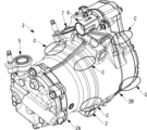
- FIG. 2 shows the compressor 2 with the enclosure 1 shown in FIG. 1 removed.
- the compressor 2 shown in the figure does not have a shape that is strictly identical to the enclosure 1 shown in FIG. 1, for example in terms of the number of mounting legs 3, but there is no significant difference in terms of the description of the compressor 2 that is sound-insulated by the enclosure 1.
- the enclosure 1 of this embodiment can be widely applied to compressors with the structure described below.
- the compressor 2 constitutes part of the refrigeration cycle used in vehicle air conditioning, sucking in the refrigerant guided from the evaporator, compressing it, and discharging the compressed refrigerant to the condenser.
- the compressor 2 has a generally cylindrical shape with its longitudinal axis in the horizontal direction.
- the compressor 2 is an electric compressor, and includes a compression section 2A having a scroll mechanism, and a motor section (electric motor section) 2B equipped with an electric motor that drives the scroll mechanism.
- the motor section 2B is connected to the rear of the compression section 2A and is located on the rear side of the compressor 2 (on the right side in FIG. 2).
- the motor section 2B includes an electric motor having a stator and a rotor, and an inverter section that supplies power to the electric motor.
- the diameter of the motor section 2B is larger than the diameter of the compression section 2A.
- a cylindrical suction port 7 is provided at the top of the motor section 2B to draw the refrigerant into the compressor 2.
- a cylindrical wiring guide tube (extension) 9 is provided at the top of the motor section 2B near the suction port (extension) 7 to guide harnesses such as power cables and signal lines to the outside of the compressor 2.
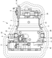
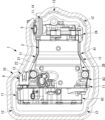
- FIG. 3 shows a vertical cross section of the compressor 2 in FIG. 2 with the enclosure 1 attached. Note that the compressor 2 in FIG. 3 is reversed from the compressor 2 shown in FIG. 2, with the compression section 2A on the right and the motor section 2B on the left. In other words, FIG. 3 is a vertical cross section seen from the rear side of FIG. 2.
- the main body 10 of the enclosure 1 has a double structure including a first cover 21 and a second cover 22.
- a gap of, for example, 5 mm to 20 mm is provided between the first cover 21 and the compressor 2, and the first cover 21 is in contact with the compressor 2 at multiple points via the first connection part 11.
- the first connection part 11 has a protruding shape that protrudes from the inner surface of the first cover 21, and the tip of the first connection part 11 is in contact with the outer surface of the compressor 2.
- the first connection part 11 is preferably made of a material softer than the material of the first cover 21, and may be, for example, a rubber sponge such as an EPDM (ethylene propylene diene rubber) foam material such as Eptsealer (registered trademark), open-cell polyethylene, or the like.
- the first connection part 11 is preferably fixed to the inner surface of the first cover 21 by adhesion or the like.
- the first connection parts 11 are mainly provided on the motor section 2B of the compressor 2. More specifically, they are provided on the front end A1, rear end A2, and intermediate section A3 of the motor section 2B. The first connection parts 11 on the intermediate section A3 can be omitted as appropriate.
- the first connection parts 11 are provided at multiple locations in the circumferential direction of the compressor 2. For example, as shown by arrow C in FIG. 2, they are provided on both the lower and upper sides of the compressor 2. As in this embodiment, it is preferable to provide more first connection parts 11 on the motor section 2B than on the compression section 2A.
- a hole is formed in the main body 10 at a position corresponding to the discharge port 5 so that the discharge port 5 can be inserted therethrough.
- a sealant 14 is provided as the first connection part 11 as shown in FIG. 3. The sealant 14 is arranged so as to wrap around the outer periphery of the cylindrical part of the discharge port 5.
- the second cover 22 encloses the entire first cover 21 inside.
- the second cover 22 has a higher density than the first cover 21 (higher specific gravity and lower air bubble rate) and is rigid enough to maintain its shape under its own weight.
- the material used for the first cover 21 is a hard resin material that does not foam or foams only to a small extent.
- the second cover 22 can be made of a rigid plastic material such as PP (polypropylene) or PBT (polybutylene terephthalate).
- the outer surface of the first cover 21 and the inner surface of the second cover 22 are in contact.
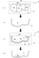
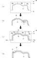
- the second cover 22 is molded using a mold 30.
- the mold 30 includes an upper mold 31 and a lower mold 32.
- the inner surface of the lower mold 32 has a shape corresponding to the outer surface of the second cover 22 after molding.
- the upper mold 31 is divided into four split molds 34a, 34b, 34c, and 34d by three shims 33a, 33b, and 33c.
- the first split mold 34a located at the top forms the entire upper part of the upper mold 31, and a plate-like first shim 33a extending horizontally is inserted into a recess formed on the bottom surface. By inserting the first shim 33a, the bottom surface of the first split mold 34a becomes flush.
- the second split mold 34b, the third split mold 34c, and the fourth split mold 34d are arranged horizontally from the left in contact with the bottom surface of the first split mold 34a.
- a plate-like second shim 33b extending vertically is provided between the second split mold 34b and the third split mold 34c, and a plate-like third shim 33c extending vertically is provided between the third split mold 34c and the fourth split mold 34d.
- the shape formed by the underside of the second split mold 34b, the underside of the second shim 33b, the underside of the third split mold 34c, the underside of the third shim 33c, and the underside of the fourth split mold 34d corresponds to the shape of the inner surface of the second cover 22.
- the above-mentioned mold 30 has a cavity set to the thickness of the second cover 22. Resin material that does not contain a foaming agent is supplied to the cavity of this mold 30, and the second cover 22 is molded at a low temperature of about 20 to 30°C (first step). Polyurethane and polyisocyanurate can be used as the resin material. PP (polypropylene) and PBT (polybutylene terephthalate) can also be used as the resin material.
- a release agent is applied to the inner surface of the molded second cover 22 to form a release layer 36.
- a release sheet may be used instead of the release agent.
- the second cover 22 and the release layer 36 are placed on the lower mold 32.
- the process of forming the release layer 36 on the second cover 22 in FIG. 4(b) may be performed after the first process in FIG. 4(a) with the upper mold 31 removed and the second cover 22 placed in the lower mold 32.
- the upper mold 31 is configured with only the four split molds 34a, 34b, 34c, and 34d after the three shims 33a, 33b, and 33c have been removed.
- the cavity formed between the upper mold 31 and the lower mold 32 is the total thickness of the first cover 21 and the second cover 22.
- the split molds 34a, 34b, 34c, and 34d can be used in common when molding the second cover 22 and when molding the second cover 22 and the first cover 21.
- the resin material mixed with the foaming agent is molded into the first cover 21 at a high temperature of 60°C or higher (second process).
- the resin material used is polyurethane, polyisocyanurate, etc.
- first cover 21 and the second cover 22 are removed from the mold 30, and the first cover 21 and the second cover 22 are separated using the release layer 36.
- the inner and outer surfaces of the separated first cover 21 are removed by blasting, machining, or the like.
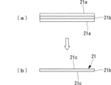
- the molded first cover 21 has a core layer 21b that serves as a foamed layer, and skin layers 21a that serve as solid layers on the front and back sides of the core layer 21b.
- a foamed surface 21c appears on the surface of the first cover 21, exposing numerous dents caused by foaming, as shown in FIG. 5(b).
- the first cover 21 is molded in a state in which the second cover 22 is placed in the mold 30.
- the second cover 22 is provided to house the first cover 21, the sound generated by the compressor 2 is converted to thermal energy and attenuated as it propagates through the first cover 21. Then, the sound is reflected to the inside by the second cover 22, which has a higher density than the first cover 21. The reflected sound is further attenuated by the first cover 21.
- the low-density first cover 21 and the high-density second cover 22 can reduce the propagation of the sound of the compressor 2 to the outside of the enclosure 1.
- the release layer 36 is formed before the second process, the first cover 21 and the second cover 22 are not bonded together. This reduces the propagation of vibration from the first cover 21 to the second cover 22. In addition, the reflection and attenuation of sound waves at the boundary between the first cover 21 and the second cover 22 reduces the propagation of sound to the outside air.
- first cover 21 and the second cover 22 are made of the same resin material, such as polyurethane or polyisocyanurate, material costs can be reduced and the manufacturing process can be simplified.
- the enclosure 1 of the first embodiment is configured such that no space is formed between the first cover 21 and the second cover 22, but the enclosure 1 of this embodiment is different in that a space is formed between the first cover 21 and the second cover 22.
- the second embodiment is similar to the first embodiment in other configurations, so the same reference numerals are used and the description thereof will be omitted.
- the second connection portion 12 has a protrusion shape that protrudes from the inner surface of the second cover 22, and the tip of the second connection portion 12 contacts the outer surface of the first cover 21.
- the second connection part 12 is provided at a different position from the first connection part 11 when the first connection part 11 is viewed from the second cover 22. In other words, the second connection part 12 does not overlap the area in which the first connection part 11 exists. This prevents the first connection part 11, the first cover 21, the second connection part 12, and the second cover 22 from being continuously present in the thickness direction of the main body part 10.
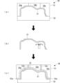
- the first cover 21 is molded using a mold 40.
- the mold 40 includes an upper mold 41 and a lower mold 42.
- the inner surface of the lower mold 42 has a shape corresponding to the inner surface of the first cover 21 after molding.
- the upper mold 41 is divided into three split molds 44a, 44b, and 44c. From the left, the first split mold 44a, the second split mold 44b, and the third split mold 44c are arranged in contact with each other horizontally.
- the shape formed by the lower surface of the first split mold 44a, the lower surface of the second split mold 44b, and the lower surface of the third split mold 44c corresponds to the shape of the outer surface of the first cover 21.
- the above-mentioned mold 40 has a cavity set to the thickness of the first cover 21.
- a resin material containing a foaming agent is supplied to the cavity of this mold 40, and the first cover 21 is molded at a high temperature of 60°C or higher (first process).
- Polyurethane, polyisocyanurate, etc. are used as the resin material.
- the first cover 21 is removed, and the inner and outer skin layers 21a (see Figure 5) are removed in the same manner as in the first embodiment.
- a release layer 46 is formed on the outer surface of the first cover 21.
- the thickness of the release layer 46 is set to a dimension equivalent to the gap between the first cover 21 and the second cover 22 when configured as the enclosure 1 as shown in FIG. 6.
- a through hole (hole) is formed in a predetermined position of the release layer 46 at a position corresponding to the second connection portion 12 (see FIG. 6).
- the first cover 21 on which the release layer 46 has been formed is placed on the lower mold 32, and the upper mold 41 on which the shims 43a, 43b, and 43c are placed is placed.
- the first shim 43a is inserted so as to be positioned around the cavity formed by the upper mold 41 and the lower mold 42.
- the second shim 43b is inserted between the first split mold 44a and the second split mold 44b, and the third shim 43c is placed between the second split mold 44b and the third split mold 44c.
- a cavity having a shape corresponding to the first cover 21, the release layer 46, and the second cover 22 is formed by these shims 43a, 43b, and 43c.
- the second cover 22 is molded at a low temperature of about 20 to 30°C using a resin material that does not contain a foaming agent (second process).
- the resin material used is the same as the first cover, such as polyurethane or polyisocyanurate.
- the first cover 21 and the second cover 22 are removed from the mold 40, and the release layer 46 is removed to form a space between the first cover 21 and the second cover 22.
- the second connection portion 12 is formed by the through holes formed in the release layer 46. The tip of the second connection portion 12 is joined in a state where it is embedded in the numerous recesses that appear on the outer surface of the first cover 21.
- the second cover 22 is molded in a state in which the first cover 21 is placed in the mold 40. This makes it possible to easily mold the second cover 22 having an inner surface having a shape corresponding to the outer surface of the first cover 21.
- the thickness of the release layer 46 is set to a thickness corresponding to the gap between the first cover 21 and the second cover 22 when the cover 46 is attached to the compressor 2. This makes it possible to form a desired gap between the first cover 21 and the second cover 22. By forming a space between the first cover 21 and the second cover 22, the propagation of vibration from the first cover 21 to the second cover 22 can be reduced.
- Through holes are formed in the release layer 46 so that the resin material flows through the through holes into the opposing first cover during the second process.
- the molded portion corresponding to the through holes becomes the second connection portion 12, which connects the first cover 21 and the second cover 22.
- the resin material of the second cover 22 fills many recesses in the surface of the first cover 21, making the mechanical bond stronger. Since a space can be formed between the first cover 21 and the second cover 22 by the multiple second connection portions 12, the propagation of vibration from the first cover 21 to the second cover 22 can be reduced.
- the first cover 21 and the second cover 22 are made of the same resin material, such as polyurethane or polyisocyanurate, so that a chemical bonding force can be added at the joint between the second connection part 12 and the first cover 21.
- the first cover 21 is molded using a mold 50.
- the mold 40 includes an upper mold 51 and a lower mold 52.
- the inner surface of the lower mold 52 has a shape corresponding to the inner surface of the first cover 21 after molding.
- the upper mold 51 is divided into three split molds 54a, 54b, and 54c. From the left, the first split mold 54a, the second split mold 54b, and the third split mold 54c are arranged in contact with each other horizontally.
- the shape formed by the bottom surface of the first split mold 54a, the bottom surface of the second split mold 54b, and the bottom surface of the third split mold 54c corresponds to the shape of the outer surface of the first cover 21.
- the mold 50 described above has a cavity set to the thickness of the first cover 21.
- a resin material containing a foaming agent is supplied to the cavity of the mold 50, and the first cover 21 is molded at a high temperature of 60°C or higher (first process).
- Polyurethane, polyisocyanurate, etc. are used as the resin material.
- the molded first cover 21 is removed, and the inner and outer skin layers 21a (see FIG. 5) are removed in the same manner as in the first embodiment.
- the first cover 21 is placed on the lower mold 52 without forming a release layer, and then the upper mold 51 with the shims 53a, 53b, and 53c placed thereon is placed.
- the first shim 53a is inserted so as to be positioned around the cavity formed by the upper mold 51 and the lower mold 52.
- the second shim 53b is inserted between the first split mold 54a and the second split mold 54b, and the third shim 53c is placed between the second split mold 54b and the third split mold 54c.
- These shims 53a, 53b, and 53c form a cavity having a shape corresponding to the first cover 21 and the second cover 22.
- the second cover 22 is molded at a low temperature of about 20 to 30°C using a resin material that does not contain a foaming agent (second process).
- the resin material used is polyurethane, polyisocyanurate, etc., the same as for the first cover. This second process results in an enclosure 1 in which the first cover 21 and the second cover 22 are joined together.
- the first cover 21 and the second cover 22 can be firmly bonded together. This makes it possible to suppress the generation of contact noise between the first cover 21 and the second cover 22 caused by the bonded portion peeling off. By bonding the first cover 21 and the second cover 22 together, the first cover 21 can absorb and dampen the vibration of the second cover 22.
- the first cover 21 and the second cover 22 are made of the same resin material, such as polyurethane or polyisocyanurate, so that a chemical bonding force can be added at the joint between the second connection part 12 and the first cover 21.
- the first cover 21 and the second cover 22 are described on the assumption that they are made of a foamed resin material, but other porous resin materials may be used.
- a porous resin material may be used in which nitrogen or carbon dioxide is blown in during kneading of the resin material without using a foaming agent, making the resin porous.
- nitrogen or carbon dioxide is not blown in during kneading of the resin.
- the method for manufacturing a compressor enclosure (1) is a method for manufacturing a compressor enclosure that includes a first cover (21) that houses and surrounds a compressor (2) therein, and a second cover (22) that houses and surrounds the first cover and has a higher density than the first cover, and includes a first step of molding the second cover or the first cover in a mold (30, 40, 50), and a second step of molding the first cover or the second cover with the molded second cover or the first cover placed in the mold.
- the first cover is molded with the second cover placed in the mold, which makes it possible to easily mold the first cover having an outer surface with a shape corresponding to the inner surface of the second cover.
- the second cover is molded after the first cover is molded while the first cover is placed in a mold, thereby making it possible to easily mold the second cover having an inner surface that corresponds to the outer surface of the first cover. Since the second cover is provided to house the first cover, the sound generated by the compressor is converted to thermal energy and attenuated as it propagates through the first cover. The sound is then reflected to the inside by the second cover, which has a higher density than the first cover. The reflected sound is further attenuated by the first cover.
- the material of the first cover has a rigidity sufficient to bend under its own weight, and may be, for example, a foamed resin material (such as soft PUR foam) made by foaming polyurethane, polyisocyanurate, or the like.
- the material for the second cover is, for example, rigid enough to maintain its shape without bending under its own weight, and may be, for example, a plastic material such as PP (polypropylene) or PBT (polybutylene terephthalate), or a hard resin material that does not foam or foams only to a small extent like the material used for the first cover.
- a plastic material such as PP (polypropylene) or PBT (polybutylene terephthalate)
- a hard resin material that does not foam or foams only to a small extent like the material used for the first cover.
- the method for manufacturing a compressor enclosure according to the second aspect of the present disclosure includes, in the first aspect, a step of removing the surface layer of the inner and/or outer surface of the first cover after molding the first cover.
- the first cover After molding, the first cover has a porous core layer located toward the center in the thickness direction, and solid skin layers formed on the inner and outer surfaces.
- a release layer (36, 46) is formed on the molded second cover or the molded first cover placed in the mold before the second step.
- the release layer may be formed by applying a liquid release agent, or may be a release sheet.
- the thickness of the release layer corresponds to the gap between the first cover and the second cover when attached to the compressor.
- the thickness of the release layer is set to a thickness corresponding to the gap between the first cover and the second cover when the cover is attached to the compressor, thereby making it possible to form a desired gap between the first cover and the second cover.
- the method for manufacturing a compressor enclosure according to the fifth aspect of the present disclosure is the third or fourth aspect, in which a plurality of holes are formed in the release layer.
- the resin material flows through the holes into the opposing first cover or second cover during the second step.
- the molded portion corresponding to the holes becomes a connecting portion, connecting the first cover and the second cover.
- the resin material of the second cover flows into the surface of the first cover and is molded, the resin material fills many recesses on the surface, making the mechanical bond stronger. Since a space can be formed between the first cover and the second cover by the multiple connection parts, it is possible to reduce the transmission of vibration from the first cover to the second cover.
- the second step is carried out without forming a release layer.
- the first cover and the second cover can be firmly bonded together. This makes it possible to suppress the generation of contact noise between the first cover and the second cover caused by the bonded portion peeling off.
- the first cover can absorb and dampen the vibrations of the second cover.
- the first and second steps use the same resin material and change the molding temperature depending on the first and second covers to be molded.
- Second connection portion Sealing material 21 First cover 21a Skin layer 21b Core layer 21c Foamed surface 22 Second cover 30, 40, 50 Mold 31, 41, 51 Upper mold 32, 42, 52 Lower mold 33a, 43a, 53a First shim 33b, 43b, 53b Second shim 33c, 43c, 53c Third shim 34a, 44a, 54a First split mold 34b, 44b, 54b Second split mold 34c, 44c, 54c Third split mold 34d Fourth split mold 36, 46 Release layer P Split surface
Landscapes
- Engineering & Computer Science (AREA)
- Mechanical Engineering (AREA)
- General Engineering & Computer Science (AREA)
- Compressor (AREA)
Applications Claiming Priority (2)
| Application Number | Priority Date | Filing Date | Title |
|---|---|---|---|
| JP2023096263A JP2024177879A (ja) | 2023-06-12 | 2023-06-12 | 圧縮機用エンクロージャの製造方法 |
| JP2023-096263 | 2023-06-12 |
Publications (1)
| Publication Number | Publication Date |
|---|---|
| WO2024257702A1 true WO2024257702A1 (ja) | 2024-12-19 |
Family
ID=93852132
Family Applications (1)
| Application Number | Title | Priority Date | Filing Date |
|---|---|---|---|
| PCT/JP2024/020862 Ceased WO2024257702A1 (ja) | 2023-06-12 | 2024-06-07 | 圧縮機用エンクロージャの製造方法 |
Country Status (2)
| Country | Link |
|---|---|
| JP (1) | JP2024177879A (cg-RX-API-DMAC7.html) |
| WO (1) | WO2024257702A1 (cg-RX-API-DMAC7.html) |
Citations (3)
| Publication number | Priority date | Publication date | Assignee | Title |
|---|---|---|---|---|
| JPS5567425A (en) * | 1978-11-16 | 1980-05-21 | Kasai Kogyo Co Ltd | Production of multilayer molding |
| JPS6357149U (cg-RX-API-DMAC7.html) * | 1986-10-02 | 1988-04-16 | ||
| JP2022147641A (ja) * | 2021-03-23 | 2022-10-06 | 株式会社豊田自動織機 | 電動圧縮機 |
-
2023
- 2023-06-12 JP JP2023096263A patent/JP2024177879A/ja not_active Withdrawn
-
2024
- 2024-06-07 WO PCT/JP2024/020862 patent/WO2024257702A1/ja not_active Ceased
Patent Citations (3)
| Publication number | Priority date | Publication date | Assignee | Title |
|---|---|---|---|---|
| JPS5567425A (en) * | 1978-11-16 | 1980-05-21 | Kasai Kogyo Co Ltd | Production of multilayer molding |
| JPS6357149U (cg-RX-API-DMAC7.html) * | 1986-10-02 | 1988-04-16 | ||
| JP2022147641A (ja) * | 2021-03-23 | 2022-10-06 | 株式会社豊田自動織機 | 電動圧縮機 |
Also Published As
| Publication number | Publication date |
|---|---|
| JP2024177879A (ja) | 2024-12-24 |
Similar Documents
| Publication | Publication Date | Title |
|---|---|---|
| CN102019885B (zh) | 隔音罩及其制造方法 | |
| US5866052A (en) | Process of manufacturing structural body for automotive vehicle | |
| CN103339669A (zh) | 隔音材料及其制造方法、以及隔音成型体和隔音方法 | |
| US7182382B2 (en) | Resin-made floor panel structure | |
| CN110870327A (zh) | 扬声器系统及车辆车门 | |
| JP7129553B2 (ja) | 自動車用空調装置のコンプレッサ | |
| CN1332801C (zh) | 用于形成吸音层系统的直接发泡背衬的方法 | |
| JP6771029B2 (ja) | シール部材およびその製造方法と乗物用ドアおよび建物用ドア | |
| JP2024177879A (ja) | 圧縮機用エンクロージャの製造方法 | |
| WO2024257701A1 (ja) | 圧縮機用エンクロージャ及び圧縮機ユニット | |
| WO2024116587A1 (ja) | 圧縮機用エンクロージャ及び圧縮機ユニット | |
| US6966592B2 (en) | Resin-made floor panel structure | |
| JP3081080B2 (ja) | 防音ユニット | |
| JP3905350B2 (ja) | 防音カバーの製造方法 | |
| JP2002087179A (ja) | 自動車用内装部品 | |
| JP2005239014A (ja) | 鉄道車両の床板 | |
| CN115427222A (zh) | 机动车的带有气垫膜的全包围的发动机罩或机组罩 | |
| JP2001138773A (ja) | インストルメントパネル及び防音構造 | |
| JP3144953B2 (ja) | 断熱壁パネル | |
| JP7572845B2 (ja) | 発泡成形品およびその製造方法と、カバー付き音源 | |
| KR100765842B1 (ko) | 흡차음 기능을 갖는 대쉬패널 | |
| EP4418260A1 (en) | Noise attenuation part and process for its production | |
| JP6851479B2 (ja) | シール部材の製造方法 | |
| JP2004070128A (ja) | 防音カバー | |
| JP2003127714A (ja) | 車室内防音構造 |
Legal Events
| Date | Code | Title | Description |
|---|---|---|---|
| 121 | Ep: the epo has been informed by wipo that ep was designated in this application |
Ref document number: 24823318 Country of ref document: EP Kind code of ref document: A1 |
|
| NENP | Non-entry into the national phase |
Ref country code: DE |
|
| 122 | Ep: pct application non-entry in european phase |
Ref document number: 24823318 Country of ref document: EP Kind code of ref document: A1 |