WO2024257589A1 - 旅客案内システムおよび旅客案内方法 - Google Patents
旅客案内システムおよび旅客案内方法 Download PDFInfo
- Publication number
- WO2024257589A1 WO2024257589A1 PCT/JP2024/019334 JP2024019334W WO2024257589A1 WO 2024257589 A1 WO2024257589 A1 WO 2024257589A1 JP 2024019334 W JP2024019334 W JP 2024019334W WO 2024257589 A1 WO2024257589 A1 WO 2024257589A1
- Authority
- WO
- WIPO (PCT)
- Prior art keywords
- control unit
- guidance
- control
- information
- station
- Prior art date
- Legal status (The legal status is an assumption and is not a legal conclusion. Google has not performed a legal analysis and makes no representation as to the accuracy of the status listed.)
- Pending
Links
Images


Classifications
-
- B—PERFORMING OPERATIONS; TRANSPORTING
- B61—RAILWAYS
- B61L—GUIDING RAILWAY TRAFFIC; ENSURING THE SAFETY OF RAILWAY TRAFFIC
- B61L25/00—Recording or indicating positions or identities of vehicles or trains or setting of track apparatus
- B61L25/02—Indicating or recording positions or identities of vehicles or trains
-
- B—PERFORMING OPERATIONS; TRANSPORTING
- B61—RAILWAYS
- B61L—GUIDING RAILWAY TRAFFIC; ENSURING THE SAFETY OF RAILWAY TRAFFIC
- B61L27/00—Central railway traffic control systems; Trackside control; Communication systems specially adapted therefor
- B61L27/30—Trackside multiple control systems, e.g. switch-over between different systems
- B61L27/33—Backup systems, e.g. switching when failures occur
Definitions
- the present invention generally relates to guidance control for providing train guidance.
- a passenger information system is a system that compiles information based on train operation information, on-line position information, and signal equipment information, and provides train information within stations.
- the control device a component of a passenger information system, has been constructed by storing an application on hardware connected to the on-site network of each station.
- Patent Document 1 states that "the traffic management system 100 includes a control device 1, multiple display devices 3, and multiple operation devices 4.
- the control device 1 is constructed in a cloud environment and individually manages the operation of trains 9 of multiple railway operators 21, 22, and 23.
- the multiple display devices 3 are provided for each of the multiple railway operators 21, 22, and 23.
- the multiple operation devices 4 are provided for each of the multiple railway operators 21, 22, and 23.
- the control device 1 causes information indicating the operation status of trains 9 of the corresponding railway operator of the multiple railway operators 21, 22, and 23 to be individually displayed on each of the multiple display devices 3, and individually controls railway facilities 5 of the multiple railway operators 21, 22, and 23 based on control requests transmitted from the multiple operation devices 4" (see Patent Document 1).
- operation information and guidance information are transmitted via the Internet, so there is a problem that communication can be interrupted or delayed if a failure occurs in the cloud service or network.
- the application of the control device is built on hardware connected to the on-site network of each station, so if the device is destroyed by lightning or a disaster, there is a problem that guidance control cannot be performed for a long period of time until the failure is restored.
- the present invention was made in consideration of the above points, and aims to propose a passenger guidance system that can continuously perform guidance control.
- the present invention provides a passenger guidance system that includes a first control unit and a second control unit capable of executing guidance control that generates guidance information for providing train guidance in a guidance unit installed within a station, the first control unit being installed on the station's in-house network and the second control unit being installed on the cloud, and the guidance control being provided redundantly by the first control unit and the second control unit.
- one of the control units capable of executing guidance control is provided on the station's in-house network, and the other control unit capable of executing guidance control is provided on the cloud.
- guidance control can be executed by the first control unit provided on the in-house network, and if an abnormality occurs in the first control unit due to a lightning strike, disaster, etc., guidance control can be executed by the second control unit provided on the cloud.
- the present invention makes it possible to realize a highly reliable passenger information system.
- Other issues, configurations, and advantages will become clear from the description of the embodiments below.
- FIG. 1 is a diagram showing an example of the configuration of a passenger guidance system according to a first embodiment
- FIG. 11 illustrates an example of a process executed by a secondary system according to the first embodiment
- FIG. 11 is a diagram showing an example of the configuration of a passenger guidance system according to a second embodiment
- FIG. 11 is a diagram illustrating an example of a process executed by a cloud control device according to the second embodiment.
- a passenger guidance system includes a control unit that compiles guidance information based on train operation information, track location information, and signal equipment information, and controls guidance for guidance units such as display devices and broadcasting devices within the station.
- a control unit that compiles guidance information based on train operation information, track location information, and signal equipment information, and controls guidance for guidance units such as display devices and broadcasting devices within the station.
- one system of the control unit is constructed on hardware connected to the station's in-house network, and the other system of the control unit is constructed in a cloud environment, resulting in a redundant configuration for guidance control (control unit).
- first,” “second,” “third,” and the like in this specification are used to identify components and do not necessarily limit the number or order. Furthermore, numbers for identifying components are used in different contexts, and a number used in one context does not necessarily indicate the same configuration in another context. Furthermore, there is no prohibition on a component identified by a certain number also serving the function of a component identified by another number.
- 100 indicates a passenger information system according to a first embodiment as a whole.
- FIG. 1 shows an example of the configuration of the passenger information system 100.
- the passenger information system 100 is a system that provides train information to railway passengers within a station by controlling various devices within the station based on train operation information, on-line position information, signal equipment information, and station setting information.
- the passenger information system 100 is mainly composed of a 1-system control device 110, a 2-system control device 120, a station setting device 130, and a guidance unit 140.
- a 1-system control device 110 an application that executes guidance control is constructed on hardware installed at each station.
- the 2-system control device 120 an application that executes guidance control is constructed in a cloud environment.
- the guidance unit 140 is composed of a guidance display 141 and a broadcasting device 142.
- the station setting device 130, the information display device 141, the broadcasting device 142, etc. are considered to be components of the passenger information system 100, but these devices do not necessarily have to be components, and devices not mentioned above may also be components. There is no limit to the number of devices that are components.
- the control device 110, station setting device 130, and guidance unit 140 of system 1 belong to the same network (in-house network), and the network to which these devices belong is called the passenger information network 101.
- the passenger information network 101 is connected to the operation management device 150, interlocking device 160, and external network via relay devices such as routers.
- the control device 120 of system 2 is constructed in a cloud environment on the external network.
- the control device 120 of system 2 is connected to the passenger information network 101, operation management device 150, interlocking device 160, and external device 170 via relay devices.
- the operation management device 150 is a higher-level device such as a central management device that manages train timetable information, etc., and transmits train operation information and on-line position information to the control device 110 of system 1 and the control device 120 of system 2.
- the interlocking device 160 is a higher-level device that manages signal equipment information such as the current signal status and track circuit drop-off status, and transmits signal equipment information to the control device 110 of system 1 and the control device 120 of system 2.
- the external device 170 may be a maintenance terminal owned by a system vendor, a terminal carried by a station staff member, etc.
- the control device 110 of the first system is constructed within the passenger information network 101.
- the control device 110 of the first system receives operation information and on-line position information from the operation management device 150 via the relay device, receives signal equipment information from the interlocking device 160, and receives station setting information from the station setting device 130, and transmits guidance information edited based on the received information to the guidance unit 140 in the passenger information network 101.
- guidance control the control of editing guidance information based on operation information, on-line position information, signal equipment information, and station setting information and outputting it to the guidance unit 140 is called guidance control.
- the control device 120 of the second system is constructed on a cloud environment.
- the control device 120 of the second system receives operation information and on-line position information from the operation management device 150 via a relay device, receives signal equipment information from the interlocking device 160, and receives station setting information from the station setting device 130, and transmits guidance information edited based on the received information to the guidance section 140 in the passenger guidance network 101.
- the control device 120 of the second system is also capable of receiving requests from an external device 170 via a relay device.
- the station setting information is received from the station setting device 130, but it may be received from an external device 170.
- the editing of the guidance information may be based on received information other than operation information, track location information, signal equipment information, and station setting information.
- the station setting device 130 is constructed within the passenger information network 101, and creates station setting information through operation by station staff, and transmits the station setting information to the control device 110 of system 1 and the control device 120 of system 2.
- the guidance unit 140 includes a guidance display 141 and a broadcast device 142.
- the guidance unit 140 receives guidance information transmitted from the control device 110 of the first system or the control device 120 of the second system.
- the guidance information includes at least one of the guidance display information received by the guidance display 141 and the guidance broadcast information received by the broadcast device 142.
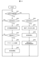
- FIG. 2 is a diagram showing an example of processing executed by the slave system.
- the master system is the control device 110 of system 1
- the slave system is the control device 120 of system 2
- the operation will be explained with the slave control device 120 of system 2 as the subject.
- a configuration in which the master system is the control device 120 of system 2 and the slave system is the control device 110 of system 1 is not excluded.
- the method of detecting a failure (abnormality) in the master system is to monitor the survival of the control devices, but a failure in the master system may be detected by other methods, such as notification by a higher-level device, station staff, etc.
- step S201 the control device 120 of the second system checks the survival information of the control device 110 of the first system.
- the survival information is information that is sent and received periodically between the control device 110 of the first system and the control device 120 of the second system for the purpose of monitoring each other's survival.
- Each control device determines that the status of the other control device is normal by receiving the survival information sent by the other control device.
- the control device 120 of the second system determines that it was unable to receive the survival information of the control device 110 of the first system, it proceeds to step S202, and if it determines that it was able to receive the survival information of the control device 110 of the first system, it proceeds to step S206.
- step S202 the control device 120 of the second system checks whether guidance control has already started. If the control device 120 of the second system determines that guidance control has started, it proceeds to step S201, and if it determines that guidance control has not started, it proceeds to step S203.
- step S203 the control device 120 of the second system updates the time when the survival information from the control device 110 of the first system was lost. When the update is complete, the control device 120 of the second system proceeds to step S204.
- step S204 the control device 120 of the second system checks whether the time during which the survival information was lost exceeds the failure determination time T, which is the threshold for failure determination. If the control device 120 of the second system determines that the failure determination time T has been exceeded, it determines that the control device 110 of the first system has failed and proceeds to step S205, and if it determines that the failure determination time T has not been exceeded, it proceeds to step S201.
- step S205 the control device 120 of the second system starts guidance control. After that, the control device 120 of the second system moves the process to step S201.
- step S201 the control device 120 of the second system checks the survival information from the control device 110 of the first system.
- the control device 120 of the second system moves to step S206 in order to receive the survival information from the control device 110 of the first system.
- step S206 the control device 120 of system 2 checks whether guidance control has started. If the control device 120 of system 2 determines that guidance control has started, it proceeds to step S207. If it determines that guidance control has not started, it proceeds to step S210. Note that when the control device 110 of system 1 recovers from a failure, the control device 120 of system 2 is performing guidance control, so it proceeds to step S207.
- step S207 the control device 120 of the second system transmits data that was updated during the failure of the control device 110 of the first system (for example, stored data that is data for guidance control received from a higher-level device and stored) to the control device 110 of the first system, and synchronizes the data.
- data that was updated during the failure of the control device 110 of the first system (for example, stored data that is data for guidance control received from a higher-level device and stored)
- the process proceeds to step S208.
- step S208 the control device 120 of system 2 stops guidance control and proceeds to step S209.
- step S209 the control device 120 of the second system requests the control device 110 of the first system to start guidance control. After that, the control device 120 of the second system moves the process to step S201.
- step S210 the control device 120 of the second system receives the information edited by the control device 110 of the first system. For example, if the control device 110 of the first system has recovered from a fault and the control device 120 of the second system is not performing guidance control, the process of step S210 is performed.
- the information edited by the control device 110 of the 1st system is, for example, train location information.
- the train location information is information indicating where on the line a train is located, and is edited based on the timetable information and the signal equipment information. More specifically, the control device 110 of the 1st system detects the entrance and exit of a train by inputting the ON/OFF of the start circuit, the departure bell, etc., and identifies which train is the detected train from the timetable information.
- the train location information is necessary when the control device 110 of the 1st system and/or the control device 120 of the 2nd system are not connected to the operation management device 150, when the operation management device 150 does not transmit information equivalent to the train location information, etc.
- step S210 One of the purposes of step S210 is to prevent the control device 120 of the 2nd system from being unable to identify trains that are located on the line if there is no train location information when the control device 110 of the 1st system breaks down and the control device 120 of the 2nd system starts guidance control.
- the control device 110 of the first system detects the entrance and exit of trains based on the timetable information and signal equipment information, edits train location information indicating the detected train's location (for example, the line section where the train is located), and transmits the edited train location information to the control device 120 of the second system.
- the control device 120 of the second system can identify the train based on the train location information and execute guidance control.
- the information received by the control device 120 of the second system is not limited to the information edited by the control device 110 of the first system.
- a higher-level device that transmits data used for guidance control to the control device 110 of the first system may also transmit the data to the control device 120 of the second system, and the control device 120 of the second system may receive the data, or the control device 110 of the first system may transmit data used for guidance control received from the higher-level device to the control device 120 of the second system, and the control device 120 of the second system may receive the data.
- the control device 120 of the second system stops guidance control.
- the control device 120 of the second system may continue guidance control without transferring guidance control (guidance system) to the control device 110 of the first system. Even in this case, data synchronization with the control device 110 of the first system may be performed.
- the passenger guidance system 100 is able to avoid various risks that may impede guidance control and provide continuous guidance control.
- Various risks include network failure, equipment damage, etc.
- the control device 110 of the first system is constructed within the passenger information network 101, and is therefore not affected by cloud service failures, network failures, etc. Therefore, there is no interruption or delay in communication due to these failures, and it is possible to continue real-time guidance control.
- Real-timeness is the property of completing data processing within a required time, and is an important property for the passenger information system 100, which requires responsive guidance control triggered by train positions and signal equipment status.
- the second system control device 120 is constructed in a cloud environment, and therefore the application entity is located away from the first system control device 110. Therefore, even if the first system control device 110 breaks down due to a lightning strike, disaster, etc., the second system control device 120 can operate normally.
- control device 110 of system 1 and the control device 120 of system 2 belong to different networks, have different information transmission paths, and are installed in different locations in the hardware in which the application entities are stored, making it possible to avoid various risks that could impede guidance control.
- the control device 120 of system 2 can receive requests from an external network, which is expected to improve the efficiency of maintenance work and the convenience of setting station guidance.
- Requests from an external network refer to requests for changing the guidance system, sending and receiving data with other devices, changing station guidance settings, etc.
- Changing the guidance system refers to switching the control device 110 that controls guidance between the primary system and the secondary system (for example, switching between the control device 110 of system 1 installed at a station and the control device 110 of system 2 installed in the cloud).
- Sending and receiving data with other devices refers to sending and receiving data such as software, station-specific data, log information, etc. to and from devices such as the control device 110 of system 1 and the station setting device 130.
- Changing station guidance settings refers to changing the settings for each station related to guidance displays and broadcasts, etc.
- a data transmission/reception request can be made from an external device 170 on the system vendor's network to the control device 120 of the second system, and the data to be updated can be sent to the control device 120 of the second system. It is also possible for the external device 170 to make a data transmission/reception request to the control device 120 of the second system, and to send update data to the control device 110 of the first system and the station setting device 130.
- station staff can change settings from any location, not limited to the location where station setting device 130 is installed, which improves the work efficiency of station staff.
- the control device constructed on the cloud environment is different from the first embodiment in that it is not a slave system of a specific station in the initial state, but is activated as a slave system of the station when a failure of a control device on the station's premises network is detected.
- components having the same functions as those in the first embodiment are given the same reference numerals and their explanations are omitted, and the explanation will be focused on the differences from the first embodiment.
- FIG. 3 is a diagram showing an example of the configuration of the passenger information system 300.
- two passenger information networks 101 are considered: passenger information network 101A of Station A and passenger information network 101B of Station B.
- Passenger information network 101A of Station A is composed of a 1-system control device 110A, a station setting device 130A, and a guidance section 140A.
- Passenger information network 101B of Station B is similarly composed of a 1-system control device 110B, a station setting device 130B, and a guidance section 140B.
- Passenger information networks 101 of each station are connected to the operation management device 150, the interlocking device 160, and a control device (cloud control device 320) constructed in a cloud environment via relay devices.
- cloud control device 320 constructed in a cloud environment via relay devices.
- the cloud control device 320 is connected to the passenger information network 101A, the passenger information network 101B, the operation management device 150, the interlocking device 160, and the external device 170 via relay devices.
- the cloud control device 320 pre-stores the execution files and station-specific data of the applications of the control devices 110 of the first system of the passenger information network 101 of each station to which it is connected.
- the cloud control device 320 is not a slave to the particular station. If the 1-system control device 110 does not have a failure, the cloud control device 320 monitors the survival of the 1-system control device 110 at each station and stores the original guide edit information that the 1-system control device 110 at each station receives from the higher-level device.
- the original guide edit information corresponds to information sent to the 1-system control device 110 at each station by the operation management device 150, the interlocking device 160, and the station setting device 130 at each station.
- the original guide edit information stored in the cloud control device 320 may be simultaneously sent to the cloud control device 320 by the higher-level device that sends data to the 1-system control device 110 at each station, or the 1-system control device 110 at each station may send data received from the higher-level device to the cloud control device 320.
- the survival monitoring of the 1-system control device 110 at each station can be performed by a method of sending and receiving survival information, a method of a failure occurrence notification by station staff, etc., as in the first embodiment.
- a fault occurrence notification refers to when a fault is detected in the control device 110 of system 1 at each station, and a station staff member or the like operates a terminal to notify the cloud control device 320 of the occurrence of the fault.
- the cloud control device 320 When the cloud control device 320 detects a failure in the control device 110 of system 1 at a specific station, it starts guidance control as a secondary system for the station where the failure occurred.
- Guidance control may be performed by an application that was monitoring the status, or by starting a guidance control application on a virtual machine. Before starting guidance control, the cloud control device 320 automatically determines the applications and data required for guidance control at the station and installs them in a specified storage location. The cloud control device 320 may also perform guidance control for multiple stations as a secondary system.
- Figure 4 shows an example of the processing executed by the cloud control device 320.
- the cloud control device 320 checks the survival information of the 1-system control devices 110 installed at each station.
- the 1-system control devices 110 installed at each station refer to all 1-system control devices 110 of the passenger information network 101 to which the cloud control device 320 is connected, such as the 1-system control device 110A at station A and the 1-system control device 110B at station B. In this case, a situation is considered in which a failure has occurred in the 1-system control device 110A at station A, making it impossible to receive survival information, and processing moves to step S202.
- Steps S202, S203, and S204 are the same as those in the first embodiment.
- the cloud control device 320 determines that a failure has occurred in the control device 110A of system 1 at station A, and proceeds to step S402.
- step S402 the cloud control device 320 automatically selects data necessary for guidance control of Station A, installs it in a specified storage location, and starts the application (secondary system).
- the data necessary for guidance control of Station A refers to the executable file of the same application as the control device 110A of System 1, station-specific data, and guidance editing source information received while the control device 110A of System 1 is operating.
- the cloud control device 320 refers to a table that specifies information (including version, storage location, etc.) about the applications and station-specific data running at each station, and identifies the necessary data.
- data selection is performed automatically, but a system administrator, system operator, station staff, etc. may issue instructions from an external network.
- step S402 when the installation is completed, the cloud control device 320 starts up as a secondary system for Station A, and proceeds to step S403.
- step S403 the cloud control device 320 starts guidance control for the guidance unit 140A of Station A.
- step S401 if the cloud control device 320 receives survival information from the control device 110A of system 1, the process proceeds to steps S206, S207, S208, and S209. These steps are the same as those in the first embodiment.
- the cloud control device 320 stops guidance control and requests the control device 110A of system 1 to start guidance control. When the above operations are completed, the process proceeds to step S401.
- the cloud control device 320 is on standby to operate as a secondary system for two stations, but the number of target stations may be three or more. Also, in preparation for failure of the control device 110 of system 1 at multiple stations, multiple cloud control devices 320 may be on standby for one station. In this case, the method for selecting the cloud control device 320 to be started as a secondary system is free. Also, the configuration is not limited to one in which the cloud control device 320 is started as a secondary system for a specific station, and the cloud control device 320 may be configured to individually start up secondary systems (virtual machines, containers, etc.) for specific stations.
- secondary systems virtual machines, containers, etc.
- the cloud control device 320 starts up as a secondary system for a specific station, it is free to continue or stop monitoring the liveness of the primary system for each station.
- passenger information system 300 can be made redundant at a lower cost than in the first embodiment.
- cloud control device 320 can be started as a secondary system for any station, so it is sufficient to prepare one virtual machine for multiple stations. This makes it possible to keep the memory and storage of the cloud service contracted to a minimum, resulting in a lower cloud service contract fee.
- the cloud control device 320 identifies the station where an abnormality has occurred in the main system by monitoring the survival of the main system at each station. Then, the cloud control device 320 automatically selects and installs the data corresponding to the station where the abnormality has occurred. Once the installation is complete, the cloud control device 320 starts up as a secondary system for the station where the abnormality has occurred and starts guidance control. Using the above method, the secondary system can be automatically started up even in a passenger guidance system 300 where different data is required at each station.
- the present invention has been described as being applied to a passenger information system, but the present invention is not limited to this and can be widely applied to a variety of other systems, devices, methods, and programs.
- the second system control device 120 may be a virtual machine running on a computer, a container running on an OS (Operating System), or software running on an OS.
- One function of the second system control device 120 may be divided into multiple functions, or multiple functions may be combined into one function. Some of the functions of the second system control device 120 may be provided as a separate function, or may be included in another function. Some of the functions of the second system control device 120 may be realized by another computer that can communicate with the second system control device 120. Additionally, the same applies to the cloud control device 320, and a description thereof will be omitted.
- the configuration of the communication medium in the passenger information system is not necessarily limited.
- the communication medium may be, for example, a communication medium conforming to various communication standards such as USB (Universal Serial Bus) and RS-232C, a LAN (Local Area Network), a WAN (Wide Area Network), the Internet, a dedicated line, etc.
- connection forms e.g., communication media
- the connection forms are different, but the connection forms may be the same.
- a configuration with different connection forms can avoid a situation in which the control device cannot receive data from the higher-level device.
- a part or all of the program may be installed from a program source into a device such as a computer that realizes the control device.
- the program source may be, for example, a program distribution server connected via a network or a computer-readable recording medium (e.g., a non-transitory recording medium).
- two or more programs may be realized as one program, and one program may be realized as two or more programs.
- information such as programs, tables, and files that realize each function can be stored in a storage device such as a memory, a hard disk, or an SSD (Solid State Drive), or in a recording medium such as an IC card, an SD card, or a DVD.
- a storage device such as a memory, a hard disk, or an SSD (Solid State Drive)
- a recording medium such as an IC card, an SD card, or a DVD.
- the above-described embodiment has the following characteristic configurations, for example:
- a passenger guidance system e.g., passenger guidance system 100, passenger guidance system 300 including a first control unit (e.g., a 1-system control device 110) and a second control unit (e.g., a 2-system control device 120) capable of executing guidance control for generating guidance information for providing train guidance in a guidance unit (e.g., a guidance unit 140, a guidance display 141, a broadcasting device 142) provided within a station, wherein the first control unit is provided on the station's in-house network (e.g., a passenger guidance network 101), and the second control unit is provided on the cloud, and guidance control is made redundant by the first control unit and the second control unit.
- a guidance unit e.g., a 1-system control device 110
- a second control unit e.g., a 2-system control device 120
- one of the control units capable of executing guidance control is provided on the station's in-house network, and the other control unit capable of executing guidance control is provided on the cloud.
- guidance control can be executed by the first control unit provided on the in-house network, and if an abnormality occurs in the first control unit due to a lightning strike, disaster, etc., guidance control can be executed by the second control unit provided on the cloud.
- the first control unit is a primary system and the second control unit is a secondary system. If an abnormality occurs in the first control unit, the second control unit starts guidance control for the station (see, for example, Figures 2 and 4).
- the first control unit provided on the on-site network is the primary system, so that, for example, continuous guidance control can be realized, and guidance control can be realized that is more responsive than when the second control unit is the primary system.
- the first control unit is provided on the in-house network of each of the multiple stations, and if an abnormality occurs in the first control unit of any of the multiple stations, the second control unit identifies data to be used for executing guidance control of the station, and starts guidance control of the station using the identified data (e.g., see Figures 3 and 4).
- the first control unit and the second control unit transmit survival information to each other, and if the second control unit does not receive survival information from the first control unit for a predetermined period of time, it detects an abnormality in the first control unit and starts guidance control when it detects an abnormality in the first control unit (e.g., see Figures 2 and 4).
- the second control unit automatically starts guidance control, so guidance control can be started more quickly than if a station staff member or the like operates the device to notify the user of the occurrence of the abnormality.
- the first control unit detects the entry and exit of trains based on timetable information and signal equipment information, edits train location information indicating the detected train's location on the line, and transmits the edited train location information to the second control unit, and if an abnormality occurs in the first control unit, the second control unit identifies the train based on the train location information and performs guidance control (e.g., see Figure 2).
- the second control unit can identify the train and perform guidance control.
- the second control unit receives requests from devices provided on the station's in-house network, such as external devices 170 provided on an external network (see, for example, Figures 1 and 3).
- maintenance work and station guidance settings can be performed from any location, improving the efficiency of maintenance work and the convenience of station guidance settings.
- the first control unit and the second control unit transmit survival information to each other, and of the first control unit and the second control unit, one is a primary system and the other is a secondary system. If the secondary system does not receive survival information from the primary system for a predetermined period of time, it detects an abnormality in the primary system and starts guidance control when it detects an abnormality in the primary system (see, for example, Figures 2 and 4).
- the secondary system automatically starts guidance control, so guidance control can be started more quickly than if a station attendant or other person operates the system to notify the user of the abnormality.
- one is the primary system and the other is the secondary system, and when the primary system receives data used for guidance control (e.g., train operation information, track position information, signal equipment information) from a higher-level device (e.g., the operation management device 150, the interlocking device 160), the primary system transmits the received data to the secondary system.
- data used for guidance control e.g., train operation information, track position information, signal equipment information
- the primary system transmits the received data to the secondary system.
- the slave system when the slave system detects an abnormality in the master system and starts guidance control, it is possible to avoid a situation in which a discrepancy occurs between the guidance control being performed by the master system and the guidance control being performed by the slave system.
- one is a primary system and the other is a secondary system, and if the primary system is restored while guidance control is being performed by the secondary system, the secondary system transmits to the primary system data used for guidance control (e.g., train operation information, track position information, signal equipment information, stored data) that was received from a higher-level device (e.g., operation management device 150, interlocking device 160) during the failure of the primary system.
- the primary system data used for guidance control e.g., train operation information, track position information, signal equipment information, stored data
- a higher-level device e.g., operation management device 150, interlocking device 160
- an item listed in the format "at least one of A, B, and C” can mean (A), (B), (C), (A and B), (A and C), (B and C), or (A, B, and C).
- an item listed in the format "at least one of A, B, or C” can mean (A), (B), (C), (A and B), (A and C), (B and C), or (A, B, and C).
- 100 Passenger information system
- 110 System 1 control device
- 120 System 2 control device.
Landscapes
- Engineering & Computer Science (AREA)
- Mechanical Engineering (AREA)
- Train Traffic Observation, Control, And Security (AREA)
Abstract
案内制御を継続的に実行し得る旅客案内システムを提供する。駅の構内に設けられている案内部において列車の案内を行うための案内情報を生成する案内制御を実行可能な第1の制御部および第2の制御部を含む旅客案内システムであって、第1の制御部は、駅の構内ネットワーク上に設けられ、第2の制御部は、クラウド上に設けられ、第1の制御部および第2の制御部により案内制御が冗長化されているようにした。
Description
本発明は、概して、列車の案内を行うための案内制御に関する。
旅客案内システムは、列車の運行情報、在線位置情報、および信号設備情報に基づいて案内情報を編集し、駅の構内において列車の案内を行うシステムである。従来、旅客案内システムの構成要素である制御装置は、各駅の構内ネットワークに接続されたハードウェア上にアプリケーションを格納することで構築が行われている。
これに対して、特許文献1には、「運行管理システム100は、制御装置1と、複数の表示装置3と、複数の操作装置4とを備える。制御装置1は、クラウド環境に構築され、複数の鉄道事業者21,22,23の列車9の運行を個別に管理する。複数の表示装置3は、複数の鉄道事業者21,22,23のうち対応する鉄道事業者の各々に対して設けられる。複数の操作装置4は、複数の鉄道事業者21,22,23のうち対応する鉄道事業者の各々に対して設けられる。制御装置1は、複数の鉄道事業者21,22,23のうち対応する鉄道事業者の列車9の運行状態を示す情報を、複数の表示装置3の各々に個別に表示させ、複数の操作装置4から送信される制御要求に基づいて複数の鉄道事業者21,22,23の鉄道設備5を個別に制御する。」と記載されている(特許文献1参照)。
発明者が、旅客案内システムについて鋭意検討した結果、次の知見を得るに至った。
特許文献1に記載の技術では、運行情報および案内情報の伝達がインターネット経由で行われるため、クラウドサービスまたはネットワークに障害が発生した場合、通信の途絶および遅延が発生する問題がある。一方で、従来型の旅客案内システムでは、制御装置のアプリケーションは、各駅の構内ネットワークに接続されたハードウェア上に構築されるため、落雷、災害等による装置破壊が発生した場合、故障回復までの長い期間において案内制御を実行できないという問題がある。
本発明は、以上の点を考慮してなされたもので、案内制御を継続的に実行し得る旅客案内システム等を提案しようとするものである。
かかる課題を解決するため本発明においては、駅の構内に設けられている案内部において列車の案内を行うための案内情報を生成する案内制御を実行可能な第1の制御部および第2の制御部を含む旅客案内システムであって、前記第1の制御部は、前記駅の構内ネットワーク上に設けられ、前記第2の制御部は、クラウド上に設けられ、前記第1の制御部および前記第2の制御部により案内制御が冗長化されているようにした。
上記構成では、案内制御を実行可能な制御部の一方が駅の構内ネットワーク上に設けられ、案内制御を実行可能な制御部の他方がクラウド上に設けられている。例えば、クラウドサービスまたはネットワークに障害が発生した場合、構内ネットワーク上に設けられている第1の制御部により案内制御を実行することができ、落雷、災害等により第1の制御部に異常が発生した場合、クラウド上に設けられている第2の制御部により案内制御を実行することができる。上記構成によれば、案内制御を阻害し得る多様なリスクを回避し、案内制御を継続して実行することができる。
本発明によれば、信頼性の高い旅客案内システムを実現することができる。上記以外の課題、構成、および効果は、以下の実施の形態の説明により明らかにされる。
(I)第1の実施の形態
以下、本発明の一実施の形態を詳述する。ただし、本発明は、実施の形態に限定されるものではない。
以下、本発明の一実施の形態を詳述する。ただし、本発明は、実施の形態に限定されるものではない。
本実施の形態では、列車の運行情報、在線位置情報、および信号設備情報に基づいて案内情報を編集し、駅の構内の表示装置、放送装置等の案内部に対して案内制御を行う制御部を備える旅客案内システムについて説明する。旅客案内システムでは、制御部の片系を駅の構内ネットワークに接続されたハードウェア上に構築し、制御部の片系をクラウド環境上に構築することで、案内制御(制御部)を冗長化した構成とするものである。
上記構成では、旅客案内システムを構成する各制御部において、所属しているネットワークと、情報伝達経路と、アプリケーションの実体が格納されたハードウェアの設置場所とが異なる。上記構成によれば、ネットワーク障害、装置破壊等を原因として案内制御が継続不可となる状況を回避することができ、信頼性の高い旅客案内システムを実現できる。
本明細書等における「第1」、「第2」、「第3」等の表記は、構成要素を識別するために付するものであり、必ずしも、数または順序を限定するものではない。また、構成要素の識別のための番号は、文脈毎に用いられ、1つの文脈で用いた番号が、他の文脈で必ずしも同一の構成を示すとは限らない。また、ある番号で識別された構成要素が、他の番号で識別された構成要素の機能を兼ねることを妨げるものではない。
次に、本発明の実施の形態を図面に基づいて説明する。以下の記載および図面は、本発明を説明するための例示であって、説明の明確化のため、適宜、省略および簡略化がなされている。本発明は、他の種々の形態でも実施することが可能である。特に限定しない限り、各構成要素は、単数でも複数でも構わない。
なお、以下の説明では、図面において同一要素については、同じ番号を付し、説明を適宜省略する。また、同種の要素を区別しないで説明する場合には、枝番を含む参照符号のうちの共通部分(枝番を除く部分)を使用し、同種の要素を区別して説明する場合は、枝番を含む参照符号を使用することがある。例えば、旅客案内ネットワークを特に区別しないで説明する場合には、「旅客案内ネットワーク101」と記載し、個々の旅客案内ネットワークを区別して説明する場合には、「旅客案内ネットワーク101A」、「旅客案内ネットワーク101B」のように記載することがある。
図1において、100は、全体として第1の実施の形態による旅客案内システムを示す。図1は、旅客案内システム100の構成の一例を示す図である。
旅客案内システム100は、列車の運行情報、在線位置情報、信号設備情報、および駅設定情報に基づいて、駅の構内の各種の装置の制御を行うことで、駅の構内の鉄道利用客に対して列車の案内を行うシステムである。旅客案内システム100は、主に、1系の制御装置110、2系の制御装置120、駅設定装置130、および案内部140を含んで構成される。ここで、1系の制御装置110については、各駅に設置されたハードウェア上に案内制御を実行するアプリケーションが構築される。2系の制御装置120については、クラウド環境上に案内制御を実行するアプリケーションが構築される。案内部140は、案内表示器141、放送装置142を含んで構成される。
ここでは、例として、駅設定装置130、案内表示器141、放送装置142等を旅客案内システム100の構成要素としたが、これらの装置は、必ず構成要素である必要はなく、また、前述していない装置が構成要素となってもよい。構成要素である装置の員数は、限定されない。
1系の制御装置110、駅設定装置130、および案内部140は、同一のネットワーク(構内ネットワーク)に属し、これらの装置が属するネットワークを旅客案内ネットワーク101と呼ぶ。旅客案内ネットワーク101は、ルータ等の中継装置を介して、運行管理装置150、連動装置160、および外部ネットワークの各々と接続される。外部ネットワーク上のクラウド環境には、2系の制御装置120が構築されている。2系の制御装置120は、中継装置を介して、旅客案内ネットワーク101、運行管理装置150、連動装置160、および外部装置170の各々と接続される。
運行管理装置150は、列車のダイヤ情報等を管理する中央管理装置等の上位装置であり、1系の制御装置110と2系の制御装置120とに列車の運行情報および在線位置情報を送信する。
連動装置160は、信号機の現示状態、軌道回路の落下扛上等の信号設備情報を管理する上位装置であり、1系の制御装置110と2系の制御装置120とに信号設備情報を送信する。
外部装置170は、システムベンダが有する保守端末、駅員が携帯する端末等が該当する。
1系の制御装置110は、旅客案内ネットワーク101内に構築される。1系の制御装置110は、中継装置を介して、運行管理装置150から運行情報および在線位置情報を受信し、連動装置160から信号設備情報を受信し、駅設定装置130から駅設定情報を受信し、受信した情報を基に編集した案内情報を旅客案内ネットワーク101内の案内部140に送信する。なお、運行情報、在線位置情報、信号設備情報、および駅設定情報を基に案内情報を編集して案内部140に出力する制御のことを、案内制御と呼ぶ。
2系の制御装置120は、クラウド環境上に構築される。2系の制御装置120は、中継装置を介して、運行管理装置150から運行情報および在線位置情報を受信し、連動装置160から信号設備情報を受信し、駅設定装置130から駅設定情報を受信し、受信した情報を基に編集した案内情報を旅客案内ネットワーク101内の案内部140に送信する。また、2系の制御装置120は、中継装置を介して外部装置170から要求を受け付けることが可能である。
本実施の形態では、駅設定情報については、駅設定装置130から受信するとしたが、外部装置170から受信してもよい。また、案内情報の編集において、運行情報、在線位置情報、信号設備情報、および駅設定情報以外の受信情報を基にしてもよい。
駅設定装置130は、旅客案内ネットワーク101内に構築されており、駅員の操作により駅設定情報を作成し、1系の制御装置110と2系の制御装置120とに対して駅設定情報を送信する。
案内部140は、案内表示器141、放送装置142を含んで構成される。案内部140は、1系の制御装置110または2系の制御装置120から送信された案内情報を受信する。案内情報は、案内表示器141が受信する案内表示情報と、放送装置142が受信する案内放送情報との少なくとも1つを含む。
次に、案内制御中の主系の制御装置(主系)が案内制御不可能となった際に、従系の制御装置(従系)が代わりに案内制御を行う場面での具体的動作について、図2を参照して説明する。
図2は、従系が実行する処理の一例を示す図である。ここでは、例として、主系を1系の制御装置110とし、従系を2系の制御装置120とし、従系である2系の制御装置120を主語として動作を説明する。なお、主系を2系の制御装置120とし、従系を1系の制御装置110とする構成を排除するものではない。ここでは、主系の故障(異常)の検出の方法として制御装置同士の生存監視を行うこととしているが、上位装置、駅員等による通知等、他の方法で主系の故障の検出を行ってもよい。
まず、1系の制御装置110の故障を2系の制御装置120が検出し、2系の制御装置120が案内制御を開始するまでの具体的動作について、図2を用いて説明する。
ステップS201では、2系の制御装置120は、1系の制御装置110の生存情報を確認する。生存情報とは、1系の制御装置110と2系の制御装置120とが互いの生存監視を目的として、定周期に送受信する情報である。各制御装置は、相手の制御装置が送信した生存情報の受信により、相手の制御装置の状態を正常であると判断する。ここでは、2系の制御装置120は、1系の制御装置110の生存情報を受信できなかったと判定した場合、ステップS202に処理を移し、1系の制御装置110の生存情報を受信できたと判定した場合、ステップS206に処理を移す。
ステップS202では、2系の制御装置120は、既に案内制御を開始しているかを確認する。2系の制御装置120は、案内制御を開始していると判定した場合、ステップS201に処理を移し、案内制御を開始していないと判定した場合、ステップS203に処理を移す。
ステップS203では、2系の制御装置120は、1系の制御装置110からの生存情報が途絶した時間を更新する。2系の制御装置120は、更新が完了すると、ステップS204に処理を移す。
ステップS204では、2系の制御装置120は、生存情報が途絶した時間が、故障判定の閾値である故障判定時間Tを超えているかを確認する。2系の制御装置120は、故障判定時間Tを超えていると判定した場合、1系の制御装置110が故障していると判断し、ステップS205に処理を移し、故障判定時間Tを超えていないと判定した場合、ステップS201に処理を移す。
ステップS205では、2系の制御装置120は、案内制御を開始する。その後、2系の制御装置120は、ステップS201に処理を移す。
次に、1系の制御装置110の故障回復を2系の制御装置120が検出し、2系の制御装置120が案内制御を停止し、1系の制御装置110が案内制御を再開するまでの具体的動作について、図2を用いて説明する。
ステップS201では、2系の制御装置120は、1系の制御装置110からの生存情報を確認する。1系の制御装置110の故障回復時は、2系の制御装置120は、1系の制御装置110からの生存情報を受信するため、ステップS206に処理を移す。
ステップS206では、2系の制御装置120は、案内制御を開始しているかを確認する。2系の制御装置120は、案内制御を開始していると判定した場合、ステップS207に処理を移し、案内制御を開始していないと判定した場合、ステップS210に処理を移す。なお、1系の制御装置110の故障回復時は、2系の制御装置120は、案内制御中であるため、ステップS207に処理を移す。
ステップS207では、2系の制御装置120は、1系の制御装置110の故障中に更新されたデータ(例えば、上位装置から受信して格納した案内制御用のデータである格納データ)を1系の制御装置110に送信し、データの同期を行う。2系の制御装置120は、1系の制御装置110とのデータ同期が完了すると、ステップS208に処理を移す。
ステップS208では、2系の制御装置120は、案内制御を停止し、ステップS209に処理を移す。
ステップS209では、2系の制御装置120は、1系の制御装置110に対して案内制御開始要求を行う。その後、2系の制御装置120は、ステップS201に処理を移す。
ステップS210では、2系の制御装置120は、1系の制御装置110が編集した情報を受信する。例えば、1系の制御装置110が故障回復し、2系の制御装置120が案内制御中ではない場合、ステップS210の処理が行われる。
1系の制御装置110が編集した情報とは、例えば、列車在線情報が挙げられる。列車在線情報とは、どの列車が路線上のどこに在線しているかを示す情報であり、ダイヤ情報および信号設備情報をもとに編集される。より具体的には、1系の制御装置110は、起動回路のON/OFF、発車ベル等の入力により、列車の進入および進出を検出し、検出した列車がどの列車であるのかをダイヤ情報から特定する。列車在線情報は、1系の制御装置110および/または2系の制御装置120が運行管理装置150と接続していない場合、運行管理装置150が列車在線情報に相当する情報を送信しない場合等に必要な情報である。ステップS210の目的の1つは、1系の制御装置110が故障し、2系の制御装置120が案内制御を開始する際に、列車在線情報がなければ、在線している列車について2系の制御装置120が判別できなくなることを防ぐことである。
このように、1系の制御装置110は、ダイヤ情報および信号設備情報をもとに、列車の進入および進出を検出し、検出した列車の在線(例えば、列車が位置する路線区間)を示す列車在線情報を編集し、編集した列車在線情報を2系の制御装置120に送信する。かかる構成によれば、2系の制御装置120は、1系の制御装置110に異常が発生した場合、列車在線情報をもとに列車を特定して案内制御を実行することができる。付言するならば、2系の制御装置120が受信する情報は、1系の制御装置110が編集した情報に限るものではない。例えば、案内制御に用いるデータを1系の制御装置110に送信する上位装置が、2系の制御装置120にも当該データを送信して2系の制御装置120が当該データを受信してもよいし、1系の制御装置110が、上位装置から受信した案内制御に用いるデータを2系の制御装置120に送信して2系の制御装置120が当該データを受信してもよい。
上記の動作例では、1系の制御装置110が故障回復した場合、2系の制御装置120は、案内制御を停止するとした。しかしながら、1系の制御装置110に案内制御(案内系)を委譲せず、2系の制御装置120が案内制御を継続してもよい。この場合においても、1系の制御装置110とデータ同期を行うこととしてもよい。
本実施の形態によれば、旅客案内システム100は、案内制御を阻害し得る多様なリスクを回避し、継続的な案内制御が可能である。多様なリスクとは、ネットワーク障害、装置破壊等が該当する。
1系の制御装置110は、旅客案内ネットワーク101内に構築されているため、クラウドサービス障害、ネットワーク障害等の影響を受けない。そのため、これら障害による通信の途絶および遅延が発生することがなく、リアルタイムな案内制御を継続することが可能である。リアルタイム性は、要求時間内にデータ処理が終了する性質であり、列車位置および信号設備状態を契機とした即応的な案内制御が求められる旅客案内システム100では重要な性質である。
一方、2系の制御装置120は、クラウド環境上に構築されるため、1系の制御装置110とは離れた場所にアプリケーションの実体を持つ。そのため、1系の制御装置110が落雷、災害等によって故障するような場合でも、2系の制御装置120は、正常な動作が可能である。
以上のように、1系の制御装置110と2系の制御装置120とは、所属するネットワーク、情報伝達経路、およびアプリケーションの実体が格納されたハードウェアの設置場所が異なるため、案内制御を阻害し得る多様なリスクを回避することができる。
また、本実施の形態によれば、高い信頼性を持つ旅客案内システム100を、低コストで構築することが可能である。これは、2系の制御装置120は、クラウド上に構築されるため、案内制御用の自社のハードウェアを必要としないためである。ハードウェアを必要としないことの副次的な効果として、システムベンダおよび鉄道事業者は、ハードウェアの保有にかかる固定費を削減することができる。
加えて、本実施の形態によれば、2系の制御装置120は、外部ネットワークからの要求を受信できるため、保守作業の効率の向上と駅案内設定時の利便性の向上とが見込まれる。外部ネットワークからの要求とは、案内系の変更、他装置とのデータ送受信、駅案内設定の変更等の要求を指す。案内系の変更とは、案内制御を行う制御装置110について主系と従系との切り替え(例えば、駅に設置の1系の制御装置110とクラウドに設置の2系の制御装置110との切り替え)を行うことを指す。他装置とのデータ送受信とは、1系の制御装置110、駅設定装置130等の装置に対して、ソフトウェア、駅固有データ、ログ情報等のデータ送受信を行うことを指す。駅案内設定の変更とは、案内表示、放送に関する各駅の設定等を変更することを指す。
先ず、案内系の変更の要求の活用例を説明する。ハードウェアの点検、交換、制御装置のデータ収集等の保守作業が必要である場合、案内系の変更が必要である。この時、システムベンダのネットワークから案内系の変更の要求を行うことで、外部から案内系を切り替えることができ、スムーズな保守作業が可能となる。
次に、データ送受信の要求の活用例として、ソフトウェア更新およびログ取得時の活用例を説明する。ソフトウェア更新を行う場合、従来では、システムベンダの作業員が該当駅に行き、ソフトウェアおよび駅固有データの更新を行うことが多い。本実施の形態によれば、2系の制御装置120に対して、システムベンダのネットワーク上の外部装置170からデータ送受信の要求を行い、更新するデータを2系の制御装置120に送信することが可能である。また、外部装置170から2系の制御装置120に対してデータ送受信の要求を行い、1系の制御装置110および駅設定装置130に更新データを送信することも可能である。以上の方法を用いると、遠隔でのソフトウェア更新が可能となるため、データ更新の際に人を派遣する必要がなく、作業員の実働にかかる費用を抑えることができる。また、1系の制御装置110、2系の制御装置120、および駅設定装置130の各々が有するログ情報をシステムベンダのネットワークに送信することも可能であり、迅速な障害対応も可能となる。
最後に、駅案内設定の変更の要求の活用例を説明する。旅客案内ネットワーク101が外部ネットワークと接続していない従来の状況では、駅案内設定の変更は、駅設定装置130を用いて行われる。本実施の形態によれば、外部ネットワークから駅案内設定の変更を行うことが可能であり、駅設定装置130を用いずとも、駅員が携帯する端末を用いた駅案内設定の変更が可能となる。この場合、駅員は、駅設定装置130の設置場所に限らず自由な場所から設定変更を行うことができ、駅員の業務効率を向上させることができる。
(II)第2の実施の形態
本実施の形態にかかる旅客案内システム300において、クラウド環境上に構築された制御装置は、初期状態では特定の駅の従系ではなく、駅の構内ネットワーク上の制御装置の故障を検出した場合に当該駅の従系として起動する点で、第1の実施の形態と異なる。以下においては、第1の実施の形態と同様な機能を有する構成要素については同一符号を付して説明を省略し、第1の実施の形態との相違点を中心に説明する。
本実施の形態にかかる旅客案内システム300において、クラウド環境上に構築された制御装置は、初期状態では特定の駅の従系ではなく、駅の構内ネットワーク上の制御装置の故障を検出した場合に当該駅の従系として起動する点で、第1の実施の形態と異なる。以下においては、第1の実施の形態と同様な機能を有する構成要素については同一符号を付して説明を省略し、第1の実施の形態との相違点を中心に説明する。
図3は、旅客案内システム300の構成の一例を示す図である。ここでは、例として、A駅の旅客案内ネットワーク101Aと、B駅の旅客案内ネットワーク101Bとの2つの旅客案内ネットワーク101を考える。A駅の旅客案内ネットワーク101Aは、1系の制御装置110A、駅設定装置130A、および案内部140Aを含んで構成される。B駅の旅客案内ネットワーク101Bも同様に、1系の制御装置110B、駅設定装置130B、および案内部140Bを含んで構成される。それぞれの駅の旅客案内ネットワーク101は、中継装置を介して、運行管理装置150、連動装置160、およびクラウド環境上に構築された制御装置(クラウド制御装置320)の各々と接続される。
クラウド制御装置320は、中継装置を介して、旅客案内ネットワーク101A、旅客案内ネットワーク101B、運行管理装置150、連動装置160、および外部装置170の各々と接続される。クラウド制御装置320は、接続されている各駅の旅客案内ネットワーク101の1系の制御装置110のアプリケーションの実行ファイルおよび駅固有データを予め格納している。
クラウド制御装置320は、特定の駅で1系の制御装置110に故障が発生していない場合、特定の駅の従系ではない。1系の制御装置110に故障が発生していない場合、クラウド制御装置320は、各駅の1系の制御装置110との生存監視と、各駅の1系の制御装置110が上位装置から受信する案内編集元情報の格納を行う。案内編集元情報は、運行管理装置150、連動装置160、および各駅の駅設定装置130の各々が、各駅の1系の制御装置110に対して送信した情報が該当する。クラウド制御装置320が格納する案内編集元情報については、各駅の1系の制御装置110にデータを送信する上位装置がクラウド制御装置320に同時に送信してもよいし、各駅の1系の制御装置110が上位装置から受信したデータをクラウド制御装置320に送信してもよい。各駅の1系の制御装置110の生存監視は、第1の実施の形態と同様に生存情報の送受信による方法、駅員等による故障発生通知による方法等を用いることができる。故障発生通知とは、各駅の1系の制御装置110に故障が認められた場合、駅員等が端末の操作を行うことにより、故障の発生をクラウド制御装置320に通知することを指す。
クラウド制御装置320は、特定の駅の1系の制御装置110についての故障の検出によって、故障発生駅の従系として案内制御を開始する。案内制御は、生存監視を行っていたアプリケーションが実施してもよいし、仮想マシン上で案内制御用のアプリケーションを起動することで実施してもよい。クラウド制御装置320は、案内制御を開始する前は、該当駅の案内制御に必要なアプリケーションおよびデータを自動で判断し、所定の格納場所にそれらのインストールを行う。クラウド制御装置320は、複数駅に対して従系として案内制御を行うこととしてもよい。
次に、複数の駅のうちの何れかの駅の1系の制御装置110が故障し、クラウド制御装置320が代わりに案内制御を行う場面での具体的動作について、図4を参照して説明する。ここでは、例として、A駅の1系の制御装置110Aに故障が発生した場合について、クラウド制御装置320を主語に動作を説明する。
図4は、クラウド制御装置320が実行する処理の一例を示す図である。
ステップS401では、クラウド制御装置320は、各駅に設置の1系の制御装置110の生存情報の確認を行う。各駅に設置の1系の制御装置110は、A駅の1系の制御装置110A、B駅の1系の制御装置110B等、クラウド制御装置320が接続する旅客案内ネットワーク101の1系の制御装置110全てを指す。ここでは、A駅の1系の制御装置110Aに故障が発生し、生存情報を受信できない状況を考え、ステップS202に処理が移される。
ステップS202、ステップS203、およびステップS204の各々は、第1の実施の形態と同様である。ここでは、クラウド制御装置320は、A駅の1系の制御装置110Aに故障が発生したと判断したとして、ステップS402に処理を移す。
ステップS402では、クラウド制御装置320は、A駅の案内制御に必要なデータを自動で選択し、所定の格納場所にインストールを行い、アプリケーション(従系)を起動する。A駅の案内制御に必要なデータとは、1系の制御装置110Aと同じアプリケーションの実行ファイル、駅固有データ、1系の制御装置110Aが稼働中に受信した案内編集元情報を指す。クラウド制御装置320は、各駅において稼働中のアプリケーションおよび駅固有データについての情報(バージョン、格納場所等を含む)を規定したテーブルを参照し、必要なデータを特定する。ここで、データの選択は、自動で行うこととしたが、システム管理者、システム運用者、駅員等が外部ネットワークから指示を行うとしてもよい。ステップS402において、クラウド制御装置320は、インストールが完了すると、A駅の従系として起動し、ステップS403に処理を移す。
ステップS403では、クラウド制御装置320は、A駅の案内部140Aに対して案内制御を開始する。
次に、A駅の1系の制御装置110Aが復旧した場面での具体的動作についても、図4を参照して説明する。
ステップS401において、クラウド制御装置320は、1系の制御装置110Aからの生存情報を受信した場合、ステップS206、ステップS207、ステップS208、およびステップS209に処理を移す。これらのステップについては、第1の実施の形態と同様である。クラウド制御装置320は、案内制御を停止し、1系の制御装置110Aに案内制御開始要求を行う。上記の動作が完了すると、ステップS401に処理が移される。
本実施の形態では、クラウド制御装置320は、2つの駅の従系としての稼働を待機するとしたが、対象の駅については3つ以上としてもよい。また、複数の駅での1系の制御装置110の故障に備えて、1つの駅に対し、クラウド制御装置320を複数待機させてもよい。この場合、従系として起動するクラウド制御装置320の選択方法は自由である。また、クラウド制御装置320が特定の駅の従系として起動する構成に限らず、クラウド制御装置320が特定の駅の従系(仮想マシン、コンテナ等)を個別に起動する構成であってもよい。
また、クラウド制御装置320が特定の駅の従系として起動する場合、各駅の主系の生存監視の継続または停止は自由である。
本実施の形態によれば、第1の実施の形態と比較して、低いコストで旅客案内システム300の冗長化が可能である。第1の実施の形態では、各駅に対してクラウド上の制御装置を用意する必要がある。本実施の形態では、クラウド制御装置320は、任意の駅の従系としての起動が可能であるため、複数の駅に対して1つの仮想マシンを用意すればよい。そのため、契約するクラウドサービスのメモリおよびストレージを少なく抑えることができ、クラウドサービス契約料が低くなる。
また、本実施の形態によれば、任意の駅の主系で異常が発生した場合に、該当駅の案内制御を自動で開始することができる。これは、各駅の主系の生存監視と、該当駅の案内制御に必要なデータの自動インストールによって実現される。まず、クラウド制御装置320は、各駅の主系の生存監視により、主系に異常が発生した駅を特定する。そして、クラウド制御装置320は、異常が発生した駅に対応するデータを自動で選択してインストールを行う。クラウド制御装置320は、インストールが完了すると、異常が発生した駅の従系として起動し、案内制御を開始する。以上の方法を用いると、各駅で必要なデータが異なる旅客案内システム300においても、自動で従系の起動を行うことができる。
(III)付記
上述の実施の形態には、例えば、以下のような内容が含まれる。
上述の実施の形態には、例えば、以下のような内容が含まれる。
上述の実施の形態においては、本発明を旅客案内システムに適用するようにした場合について述べたが、本発明はこれに限らず、この他種々のシステム、装置、方法、プログラムに広く適用することができる。
また、上述の実施の形態において、2系の制御装置120は、コンピュータで動作する仮想マシン(Virtual Machine)であってもよいし、OS(Operating System)上で動作するコンテナであってもよいし、OS上で動作するソフトウェアであってもよい。なお、2系の制御装置120の1つの機能は、複数の機能に分けられていてもよいし、複数の機能は、1つの機能にまとめられていてもよい。また、2系の制御装置120の機能の一部は、別の機能として設けられてもよいし、他の機能に含められていてもよい。また、2系の制御装置120の機能の一部は、2系の制御装置120と通信可能な他のコンピュータにより実現されてもよい。付言するならば、クラウド制御装置320についても同様であり、その説明を省略する。
また、上述の実施の形態において、旅客案内システムにおける通信媒体の構成は、必ずしも限定されない。通信媒体は、例えば、USB(Universal Serial Bus)、RS-232C等の各種の通信規格に準拠した通信媒体、LAN(Local Area Network)、WAN(Wide Area Network)、インターネット、専用線等である。
また、上述の実施の形態においては、運行管理装置150、連動装置160等の上位装置と、1系の制御装置110および2系の制御装置120の各々とは、接続形態(例えば、通信媒体)が異なっている場合について示したが、接続形態が同じであってもよい。付言するならば、接続形態が異なる構成によれば、制御装置が上位装置からデータを受信できなくなる事態を回避することができる。
また、上述の実施の形態において、プログラムの一部またはすべては、プログラムソースから、制御装置を実現するコンピュータのような装置にインストールされてもよい。プログラムソースは、例えば、ネットワークで接続されたプログラム配布サーバまたはコンピュータが読み取り可能な記録媒体(例えば非一時的な記録媒体)であってもよい。また、上述の説明において、2以上のプログラムが1つのプログラムとして実現されてもよいし、1つのプログラムが2以上のプログラムとして実現されてもよい。
また、上記の説明において、各機能を実現するプログラム、テーブル、ファイル等の情報は、メモリや、ハードディスク、SSD(Solid State Drive)等の記憶装置、または、ICカード、SDカード、DVD等の記録媒体に置くことができる。
上述した実施の形態は、例えば、以下の特徴的な構成を有する。
(1)
駅の構内に設けられている案内部(例えば、案内部140、案内表示器141、放送装置142)において列車の案内を行うための案内情報を生成する案内制御を実行可能な第1の制御部(例えば、1系の制御装置110)および第2の制御部(例えば、2系の制御装置120)を含む旅客案内システム(例えば、旅客案内システム100、旅客案内システム300)であって、上記第1の制御部は、上記駅の構内ネットワーク(例えば、旅客案内ネットワーク101)上に設けられ、上記第2の制御部は、クラウド上に設けられ、上記第1の制御部および上記第2の制御部により案内制御が冗長化されている。
駅の構内に設けられている案内部(例えば、案内部140、案内表示器141、放送装置142)において列車の案内を行うための案内情報を生成する案内制御を実行可能な第1の制御部(例えば、1系の制御装置110)および第2の制御部(例えば、2系の制御装置120)を含む旅客案内システム(例えば、旅客案内システム100、旅客案内システム300)であって、上記第1の制御部は、上記駅の構内ネットワーク(例えば、旅客案内ネットワーク101)上に設けられ、上記第2の制御部は、クラウド上に設けられ、上記第1の制御部および上記第2の制御部により案内制御が冗長化されている。
上記構成では、案内制御を実行可能な制御部の一方が駅の構内ネットワーク上に設けられ、案内制御を実行可能な制御部の他方がクラウド上に設けられている。例えば、クラウドサービスまたはネットワークに障害が発生した場合、構内ネットワーク上に設けられている第1の制御部により案内制御を実行することができ、落雷、災害等により第1の制御部に異常が発生した場合、クラウド上に設けられている第2の制御部により案内制御を実行することができる。上記構成によれば、案内制御を阻害し得る多様なリスクを回避し、案内制御を継続して実行することができる。
(2)
上記第1の制御部は、主系であり、上記第2の制御部は、従系であり、上記第1の制御部に異常が発生した場合、上記第2の制御部は、上記駅の案内制御を開始する(例えば、図2、図4参照)。
上記第1の制御部は、主系であり、上記第2の制御部は、従系であり、上記第1の制御部に異常が発生した場合、上記第2の制御部は、上記駅の案内制御を開始する(例えば、図2、図4参照)。
上記構成によれば、構内ネットワーク上に設けられている第1の制御部が主系であるので、例えば、継続的な案内制御を実現すると共に、第2の制御部が主系である場合と比べて即応的な案内制御を実現することができる。
(3)
上記第1の制御部は、複数の駅の各々の構内ネットワーク上に設けられ、上記複数の駅の何れかの駅の第1の制御部に異常が発生した場合、上記第2の制御部は、上記駅の案内制御の実行に用いるデータを特定し、特定したデータを用いて上記駅の案内制御を開始する(例えば、図3、図4参照)。
上記第1の制御部は、複数の駅の各々の構内ネットワーク上に設けられ、上記複数の駅の何れかの駅の第1の制御部に異常が発生した場合、上記第2の制御部は、上記駅の案内制御の実行に用いるデータを特定し、特定したデータを用いて上記駅の案内制御を開始する(例えば、図3、図4参照)。
上記構成によれば、例えば、複数の駅に対して1つの第2の制御部を用意すればよいので、用意するクラウドサービスのメモリおよびストレージを抑えることができる。
(4)
上記第1の制御部と上記第2の制御部とは、互いに生存情報を送信し、上記第2の制御部は、所定の期間、上記第1の制御部からの生存情報を受信していない場合、上記第1の制御部の異常を検出し、上記第1の制御部の異常を検出したときに案内制御を開始する(例えば、図2、図4参照)。
上記第1の制御部と上記第2の制御部とは、互いに生存情報を送信し、上記第2の制御部は、所定の期間、上記第1の制御部からの生存情報を受信していない場合、上記第1の制御部の異常を検出し、上記第1の制御部の異常を検出したときに案内制御を開始する(例えば、図2、図4参照)。
上記構成によれば、例えば、第1の制御部に異常が発生した場合に、第2の制御部が自動で案内制御を開始するので、異常の発生を通知するための駅員等による操作が行わる場合よりも案内制御を迅速に開始することができる。
(5)
上記第1の制御部は、ダイヤ情報および信号設備情報をもとに、列車の進入および進出を検出し、検出した列車の在線を示す列車在線情報を編集し、編集した列車在線情報を上記第2の制御部に送信し、上記第2の制御部は、上記第1の制御部に異常が発生した場合、上記列車在線情報をもとに列車を特定して案内制御を実行する(例えば、図2参照)。
上記第1の制御部は、ダイヤ情報および信号設備情報をもとに、列車の進入および進出を検出し、検出した列車の在線を示す列車在線情報を編集し、編集した列車在線情報を上記第2の制御部に送信し、上記第2の制御部は、上記第1の制御部に異常が発生した場合、上記列車在線情報をもとに列車を特定して案内制御を実行する(例えば、図2参照)。
上記構成によれば、例えば、第2の制御部が運行管理装置と接続していない場合、運行管理装置が列車在線情報に相当する情報を第2の制御部に送信しない場合等であっても、第2の制御部は、列車を特定して案内制御を実行することができる。
(6)
上記第2の制御部は、上記駅の構内ネットワーク上に設けられている装置に対する要求であって、外部ネットワーク上に設けられている装置(例えば、外部装置170)からの要求を受け付ける(例えば、図1、図3参照)。
上記第2の制御部は、上記駅の構内ネットワーク上に設けられている装置に対する要求であって、外部ネットワーク上に設けられている装置(例えば、外部装置170)からの要求を受け付ける(例えば、図1、図3参照)。
上記構成によれば、例えば、任意の場所から保守作業および駅の案内設定を行うことができるので、保守作業の効率を向上させたり、駅の案内設定の利便性を向上させたりすることができる。
(7)
上記第1の制御部と上記第2の制御部とは、互いに生存情報を送信し、上記第1の制御部と上記第2の制御部とにおいて、一方が主系であり、他方が従系であり、従系は、所定の期間、主系からの生存情報を受信していない場合、主系の異常を検出し、主系の異常を検出したときに案内制御を開始する(例えば、図2、図4参照)。
上記第1の制御部と上記第2の制御部とは、互いに生存情報を送信し、上記第1の制御部と上記第2の制御部とにおいて、一方が主系であり、他方が従系であり、従系は、所定の期間、主系からの生存情報を受信していない場合、主系の異常を検出し、主系の異常を検出したときに案内制御を開始する(例えば、図2、図4参照)。
上記構成によれば、例えば、主系に異常が発生した場合に、従系が自動で案内制御を開始するので、異常の発生を通知するための駅員等による操作が行われる場合よりも案内制御を迅速に開始することができる。
(8)
上記第1の制御部と上記第2の制御部とにおいて、一方が主系であり、他方が従系であり、主系が案内制御に用いるデータ(例えば、列車の運行情報、在線位置情報、信号設備情報)を上位装置(例えば、運行管理装置150、連動装置160)から受信した場合、主系は、受信したデータを、従系に対して送信する。
上記第1の制御部と上記第2の制御部とにおいて、一方が主系であり、他方が従系であり、主系が案内制御に用いるデータ(例えば、列車の運行情報、在線位置情報、信号設備情報)を上位装置(例えば、運行管理装置150、連動装置160)から受信した場合、主系は、受信したデータを、従系に対して送信する。
上記構成によれば、例えば、従系が主系の異常を検出して案内制御を開始する場合に、主系により実行されていた案内制御と従系により実行される案内制御とにズレが生じてしまう事態を回避することができる。
(9)
上記第1の制御部と上記第2の制御部とにおいて、一方が主系であり、他方が従系であり、従系による案内制御の実行中に主系が復旧した場合、従系は、主系の故障中に上位装置(例えば、運行管理装置150、連動装置160)から受信した案内制御に用いるデータ(例えば、列車の運行情報、在線位置情報、信号設備情報、格納データ)を主系に送信する。
上記第1の制御部と上記第2の制御部とにおいて、一方が主系であり、他方が従系であり、従系による案内制御の実行中に主系が復旧した場合、従系は、主系の故障中に上位装置(例えば、運行管理装置150、連動装置160)から受信した案内制御に用いるデータ(例えば、列車の運行情報、在線位置情報、信号設備情報、格納データ)を主系に送信する。
上記構成によれば、例えば、主系が復旧して案内制御を開始する場合に、主系が停止している間に従系により実行されていた案内制御と主系により実行される案内制御とにズレが生じてしまう事態を回避することができる。
また上述した構成については、本発明の要旨を超えない範囲において、適宜に、変更したり、組み替えたり、組み合わせたり、省略したりしてもよい。
「A、B、およびCのうちの少なくとも1つ」という形式におけるリストに含まれる項目は、(A)、(B)、(C)、(AおよびB)、(AおよびC)、(BおよびC)または(A、B、およびC)を意味することができると理解されたい。同様に、「A、B、またはCのうちの少なくとも1つ」の形式においてリストされた項目は、(A)、(B)、(C)、(AおよびB)、(AおよびC)、(BおよびC)または(A、B、およびC)を意味することができる。
100……旅客案内システム、110……1系の制御装置、120……2系の制御装置。
Claims (10)
- 駅の構内に設けられている案内部において列車の案内を行うための案内情報を生成する案内制御を実行可能な第1の制御部および第2の制御部を含む旅客案内システムであって、
前記第1の制御部は、前記駅の構内ネットワーク上に設けられ、
前記第2の制御部は、クラウド上に設けられ、
前記第1の制御部および前記第2の制御部により案内制御が冗長化されている、
旅客案内システム。 - 前記第1の制御部は、主系であり、
前記第2の制御部は、従系であり、
前記第1の制御部に異常が発生した場合、前記第2の制御部は、前記駅の案内制御を開始する、
請求項1に記載の旅客案内システム。 - 前記第1の制御部は、複数の駅の各々の構内ネットワーク上に設けられ、
前記複数の駅の何れかの駅の第1の制御部に異常が発生した場合、前記第2の制御部は、前記駅の案内制御の実行に用いるデータを特定し、特定したデータを用いて前記駅の案内制御を開始する、
請求項2に記載の旅客案内システム。 - 前記第1の制御部と前記第2の制御部とは、互いに生存情報を送信し、
前記第2の制御部は、所定の期間、前記第1の制御部からの生存情報を受信していない場合、前記第1の制御部の異常を検出し、前記第1の制御部の異常を検出したときに案内制御を開始する、
請求項2に記載の旅客案内システム。 - 前記第1の制御部は、ダイヤ情報および信号設備情報をもとに、列車の進入および進出を検出し、検出した列車の在線を示す列車在線情報を編集し、編集した列車在線情報を前記第2の制御部に送信し、
前記第2の制御部は、前記第1の制御部に異常が発生した場合、前記列車在線情報をもとに列車を特定して案内制御を実行する、
請求項2に記載の旅客案内システム。 - 前記第2の制御部は、前記駅の構内ネットワーク上に設けられている装置に対する要求であって、外部ネットワーク上に設けられている装置からの要求を受け付ける、
請求項1に記載の旅客案内システム。 - 前記第1の制御部と前記第2の制御部とは、互いに生存情報を送信し、
前記第1の制御部と前記第2の制御部とにおいて、一方が主系であり、他方が従系であり、
従系は、所定の期間、主系からの生存情報を受信していない場合、主系の異常を検出し、主系の異常を検出したときに案内制御を開始する、
請求項1に記載の旅客案内システム。 - 前記第1の制御部と前記第2の制御部とにおいて、一方が主系であり、他方が従系であり、
主系が案内制御に用いるデータを上位装置から受信した場合、主系は、受信したデータを、従系に対して送信する、
請求項1に記載の旅客案内システム。 - 前記第1の制御部と前記第2の制御部とにおいて、一方が主系であり、他方が従系であり、
従系による案内制御の実行中に主系が復旧した場合、従系は、主系の故障中に上位装置から受信した案内制御に用いるデータを主系に送信する、
請求項1に記載の旅客案内システム。 - 第1の制御部が、駅の構内に設けられている案内部において列車の案内を行うための案内情報を生成する案内制御を実行することと、
第2の制御部が、前記第1の制御部により案内制御が実行されていないときに、前記駅の構内に設けられている前記案内部において列車の案内を行うための案内情報を生成する案内制御を実行することと、
を含み、
前記第1の制御部は、前記駅の構内ネットワーク上に設けられ、
前記第2の制御部は、クラウド上に設けられ、
前記第1の制御部および前記第2の制御部により案内制御が冗長化されている、
旅客案内方法。
Applications Claiming Priority (2)
| Application Number | Priority Date | Filing Date | Title |
|---|---|---|---|
| JP2023097758 | 2023-06-14 | ||
| JP2023-097758 | 2023-06-14 |
Publications (1)
| Publication Number | Publication Date |
|---|---|
| WO2024257589A1 true WO2024257589A1 (ja) | 2024-12-19 |
Family
ID=93851843
Family Applications (1)
| Application Number | Title | Priority Date | Filing Date |
|---|---|---|---|
| PCT/JP2024/019334 Pending WO2024257589A1 (ja) | 2023-06-14 | 2024-05-27 | 旅客案内システムおよび旅客案内方法 |
Country Status (1)
| Country | Link |
|---|---|
| WO (1) | WO2024257589A1 (ja) |
Citations (3)
| Publication number | Priority date | Publication date | Assignee | Title |
|---|---|---|---|---|
| JP2020144575A (ja) * | 2019-03-06 | 2020-09-10 | 日本信号株式会社 | 鉄道制御システム |
| US20200290657A1 (en) * | 2017-10-16 | 2020-09-17 | Siemens Mobility GmbH | Railway automation network and method for transmitting messages in a railway automation network |
| JP2022070737A (ja) * | 2020-10-27 | 2022-05-13 | 三菱電機株式会社 | 運行管理システム、制御装置、制御方法、および制御プログラム |
-
2024
- 2024-05-27 WO PCT/JP2024/019334 patent/WO2024257589A1/ja active Pending
Patent Citations (3)
| Publication number | Priority date | Publication date | Assignee | Title |
|---|---|---|---|---|
| US20200290657A1 (en) * | 2017-10-16 | 2020-09-17 | Siemens Mobility GmbH | Railway automation network and method for transmitting messages in a railway automation network |
| JP2020144575A (ja) * | 2019-03-06 | 2020-09-10 | 日本信号株式会社 | 鉄道制御システム |
| JP2022070737A (ja) * | 2020-10-27 | 2022-05-13 | 三菱電機株式会社 | 運行管理システム、制御装置、制御方法、および制御プログラム |
Similar Documents
| Publication | Publication Date | Title |
|---|---|---|
| EP4023527A1 (en) | Subsystem and method for controlling the switch between a main center and a standby center in the integrated supervisory control system | |
| CN108032876B (zh) | 一种车站运输调度方法和系统 | |
| CN109726046A (zh) | 机房切换方法及切换装置 | |
| CN115892144B (zh) | 一种tacs系统主备定位转换方法、装置、设备及介质 | |
| KR102462414B1 (ko) | 전자식 자동폐색제어장치 및 이를 이용한 제어 방법 | |
| JP6451467B2 (ja) | 統合監視制御装置および統合監視制御システム | |
| CN115593472A (zh) | 一种列车重定位方法、装置、电子设备及介质 | |
| JP6631970B2 (ja) | Ctc駅装置およびctc装置ならびにctc復旧・更新方法 | |
| WO2024257589A1 (ja) | 旅客案内システムおよび旅客案内方法 | |
| CN105644589A (zh) | 列车运行状态信息的显示方法、装置和系统 | |
| JP6675043B2 (ja) | 監視制御システム | |
| CN114374712A (zh) | 行车管理方法、电子设备和存储介质 | |
| CN109921949A (zh) | 一种灾备系统冗余机制的实现方法 | |
| JP6675044B2 (ja) | 監視制御システム | |
| JP2009040199A (ja) | 運行管理用フォルトトレラントシステム | |
| JPH1145101A (ja) | 監視制御システム | |
| JP5364642B2 (ja) | 列車運行管理システム | |
| JP2018030541A (ja) | 連動装置 | |
| CN214165019U (zh) | 用于轨道交通系统的运控集成系统及其操作终端 | |
| JP2004034821A (ja) | 集中監視装置の切替方法およびそれに用いる切替装置 | |
| CN114706885A (zh) | 一种信息同步方法、装置、电子设备及存储介质 | |
| JP2025112092A (ja) | 運行管理システム | |
| Kunifuji | Safety Technologies in Autonomous Decentralized Railway Control System | |
| JP2907198B1 (ja) | プライベートlanを利用した無停電電源装置における電源制御方式 | |
| CN205951998U (zh) | 用于铁路信号设备系统的中央控制装置 |
Legal Events
| Date | Code | Title | Description |
|---|---|---|---|
| 121 | Ep: the epo has been informed by wipo that ep was designated in this application |
Ref document number: 24823209 Country of ref document: EP Kind code of ref document: A1 |