WO2024257434A1 - 合成燃料の製造装置及び製造方法 - Google Patents
合成燃料の製造装置及び製造方法 Download PDFInfo
- Publication number
- WO2024257434A1 WO2024257434A1 PCT/JP2024/012434 JP2024012434W WO2024257434A1 WO 2024257434 A1 WO2024257434 A1 WO 2024257434A1 JP 2024012434 W JP2024012434 W JP 2024012434W WO 2024257434 A1 WO2024257434 A1 WO 2024257434A1
- Authority
- WO
- WIPO (PCT)
- Prior art keywords
- reactor
- material gas
- synthetic fuel
- raw material
- fuel
- Prior art date
- Legal status (The legal status is an assumption and is not a legal conclusion. Google has not performed a legal analysis and makes no representation as to the accuracy of the status listed.)
- Ceased
Links
Images




Classifications
-
- C—CHEMISTRY; METALLURGY
- C10—PETROLEUM, GAS OR COKE INDUSTRIES; TECHNICAL GASES CONTAINING CARBON MONOXIDE; FUELS; LUBRICANTS; PEAT
- C10G—CRACKING HYDROCARBON OILS; PRODUCTION OF LIQUID HYDROCARBON MIXTURES, e.g. BY DESTRUCTIVE HYDROGENATION, OLIGOMERISATION, POLYMERISATION; RECOVERY OF HYDROCARBON OILS FROM OIL-SHALE, OIL-SAND, OR GASES; REFINING MIXTURES MAINLY CONSISTING OF HYDROCARBONS; REFORMING OF NAPHTHA; MINERAL WAXES
- C10G2/00—Production of liquid hydrocarbon mixtures of undefined composition from oxides of carbon
- C10G2/50—Production of liquid hydrocarbon mixtures of undefined composition from oxides of carbon from carbon dioxide with hydrogen
Definitions
- the present invention relates to a synthetic fuel manufacturing apparatus and method for producing a specific synthetic fuel, particularly jet fuel, by a direct FT synthesis reaction using a raw material gas containing hydrogen and carbon dioxide.
- a method for producing jet fuel using the Fischer-Tropsch (FT) synthesis reaction from synthesis gas containing hydrogen and carbon monoxide is known, for example as disclosed in Patent Document 1.
- FT Fischer-Tropsch
- a chemical reaction is used to synthesize alkanes from synthesis gas in a reactor filled with an FT catalyst for causing the FT synthesis reaction, and FT crude oil containing a variety of hydrocarbons is produced.
- FT crude oil containing a variety of hydrocarbons is produced.
- an FT catalyst is proposed for producing hydrocarbons with a carbon number of 5 or more at a high yield using a mixed gas of hydrogen and carbon dioxide as the raw material gas.
- This FT catalyst is composed of catalytic metals containing Fe (iron) and Zr (zirconium), Ga (gallium), and Na (sodium).
- the above-mentioned FT catalyst does not provide sufficient selectivity for synthetic fuel suitable for jet fuel, specifically synthetic fuel containing hydrocarbons with 8 to 16 carbon atoms, in the synthetic fuel produced.
- the inventors discovered that it is possible to increase the selectivity for hydrocarbons with a desired carbon number based on the relationship between the FT catalyst packed in the reactor and the flow rate and flow speed of the raw material gas supplied to the reactor, and thus completed the present invention.
- the present invention has been made to solve the above problems, and aims to provide a synthetic fuel production device and method that can obtain a specific synthetic fuel, particularly hydrocarbons with a high selectivity for jet fuel components, and produce jet fuel with a high yield.
- the invention of claim 1 is a synthetic fuel production device (synthetic fuel production device 1 in this embodiment (hereinafter the same in this section)) for producing a specified synthetic fuel by a direct FT synthesis reaction using a raw material gas containing hydrogen and carbon dioxide, and is equipped with a reactor 9 having a cylindrical reactor main body 9a and filled with a specified FT catalyst 20 for causing a direct FT synthesis reaction in the reactor main body, an adjustment unit (raw material gas flow rate adjustment unit 7 and/or composition adjustment units 5a, 5b) for adjusting the flow rate of the raw material gas supplied to the reactor, and a control means (control device 3) for controlling the linear velocity, which is the flow rate of the raw material gas per cross-sectional area of the reactor main body by controlling this adjustment unit, and the control means is characterized in that when the specified synthetic fuel is jet fuel, the linear velocity is controlled to 0.2 to 4.0 m/sec.
- the reactor has a cylindrical reactor body, and this reactor body is filled with a specified FT catalyst for causing a direct FT synthesis reaction.
- the control means controls an adjustment unit for adjusting the flow rate of the raw material gas supplied to the reactor.
- the linear velocity which is the flow rate of the raw material gas per cross-sectional area of the reactor body, is controlled to 0.2 to 4.0 m/sec.
- the invention according to claim 2 is the synthetic fuel production device according to claim 1, characterized in that the control means controls the linear velocity to 2.7 to 3.0 m/sec.
- the linear velocity can be controlled to 2.7 to 3.0 m/sec by the control means, making it possible to obtain jet fuel component hydrocarbons with a higher selectivity.
- the invention of claim 3 is a synthetic fuel manufacturing method for manufacturing a specified synthetic fuel by a direct FT synthesis reaction using a raw material gas containing hydrogen and carbon dioxide, and is characterized by comprising a reactor preparation process for preparing a reactor 9 in which a cylindrical reactor body 9a is filled with an FT catalyst for causing a direct FT synthesis reaction, and a raw material gas supply process for supplying the raw material gas to the reactor so that the linear velocity, which is the flow rate of the raw material gas per cross-sectional area of the reactor body, is 0.2 to 4.0 m/sec when the specified synthetic fuel is jet fuel.
- a reactor is prepared with a specified FT catalyst packed in the cylindrical reactor body (reactor preparation process).
- the feed gas is supplied to the reactor so that the linear velocity, which is the flow rate of the feed gas per cross-sectional area of the reactor body, is 0.2 to 4.0 m/sec (feed gas supply process).
- FIG. 1 is a diagram showing a schematic diagram of a synthetic fuel production apparatus to which a synthetic fuel production apparatus and production method according to an embodiment of the present invention are applied.
- FIG. 2A is a diagram showing a reactor packed with an FT catalyst
- FIG. 2B is a diagram for explaining the linear velocity of a raw material gas supplied to the reactor.
- 1 is a graph showing the distillation properties of synthetic fuels obtained when the feed gas is supplied to a reactor at a high linear velocity and a low linear velocity.
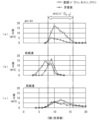
- 1 is a graph showing a hydrocarbon distribution indicating the relationship between the carbon number and weight of the hydrocarbons contained in a synthetic fuel, in which (a) shows the hydrocarbon distribution of a Jet-A1 standard jet fuel, (b) shows the hydrocarbon distribution of a synthetic fuel obtained at a low linear velocity, and (c) shows the hydrocarbon distribution of a synthetic fuel obtained at a high linear velocity.
- 1 is a graph showing the relationship between the feed gas linear velocity and the jet fuel selectivity based on test results.
- 1 is a graph showing the pore distribution, which indicates the relationship between pore size and pore volume, for two types of FT catalysts.
- FIG. 1 shows a schematic diagram of a synthetic fuel production apparatus to which a synthetic fuel production apparatus and production method according to one embodiment of the present invention is applied.
- this synthetic fuel production apparatus 1 comprises a raw material gas supply section, a composition adjustment section, a compression section, a flow rate adjustment section, a preheating section, a catalytic reaction section, a cooling section, a gas-liquid separation section, and a collection section, which are connected via piping 2 and are controlled by a control device 3 (control means).
- the raw material gas supply unit has an H2 supply unit 4a and a CO2 supply unit 4b, which supply hydrogen and carbon dioxide, respectively.
- an H2 composition adjustment unit 5a and a CO2 composition adjustment unit 5b are provided downstream of the H2 supply unit 4a and the CO2 supply unit 4b, respectively.
- these H2 composition adjustment units 5a and CO2 composition adjustment units 5b are controlled by the control device 3, and can adjust the flow rate of the raw material gas alone or in cooperation with a raw material gas flow rate adjustment unit 7 described later.
- the compression section has a compressor 6, and is controlled by the control device 3 to pressurize the raw material gas to a predetermined pressure (e.g., 3 MPa).
- the flow rate adjustment section has a raw material gas flow rate adjustment section 7, and is controlled by the control device 3 to adjust the flow rate of the raw material gas compressed by the compressor 6.
- the preheating section has a preheating tube 8a and a preheater 8b, and the preheater 8b is controlled by the control device 3, so that the raw material gas passing through the preheating tube 8a connected to the piping 2 is heated to a predetermined temperature.
- the catalytic reaction section has a reactor 9 and a temperature adjustment section 10.
- the reactor 9 has a cylindrical reactor body 9a having a predetermined inner diameter, and the reactor body 9a is filled with the FT catalyst 20.
- the preparation of the reactor 9 by filling the reactor body 9a with the FT catalyst 20 corresponds to the reactor preparation step in the synthetic fuel production method of the present invention, and this reactor preparation step may include a step of heating the inside of the reactor 9 to a predetermined temperature (such as a reaction temperature) using an inert gas or the like.
- the FT catalyst 20 is for producing a plurality of types of hydrocarbons having different carbon numbers by causing a direct FT synthesis reaction in the raw material gas supplied to the reactor 9.
- the FT catalyst 20 is similar to the FT catalyst disclosed in Japanese Patent Application No. 2022-052774 already filed by the present applicant, and specifically, is configured to contain Fe, Zr, Ga, and Na as metal catalysts.
- the FT catalyst 20 is composed of a large number of pellets each having a predetermined size and shape, and each is configured to have a large number of pores. These pores have a specific surface area of about 30 m 2 /g and an average pore diameter of 10 to 100 nm.
- the temperature adjustment unit 10 in the catalytic reaction section is controlled by the control device 3, and the direct FT synthesis reaction occurring in the reactor 9 is adjusted to a predetermined temperature (e.g., 380°C).
- the raw material gas is kept at high pressure from the compression section to the catalytic reaction section described above, and as shown by the one-dot chain line in Figure 1, the raw material gas is heated from the preheating section to the catalytic reaction section.
- the cooling section has a cooler 11, and the product discharged from the reactor 9 is cooled by controlling the cooler 11 with the control device 3.
- the gas-liquid separation section has a gas-liquid separator 12, which separates the product that has been liquefied by cooling in the cooler 11 from the gaseous post-reaction gas that has not reacted or has not been liquefied.
- a gas-liquid separator 12 which separates the product that has been liquefied by cooling in the cooler 11 from the gaseous post-reaction gas that has not reacted or has not been liquefied.
- the collection section has a collection tank 13, which collects the liquid product separated by the gas-liquid separator 12.
- the synthetic fuel production device 1 configured as described above, as shown below, by causing a direct FT synthesis reaction while controlling the linear velocity of the raw material gas supplied to the reactor 9 within a predetermined range, it is possible to obtain synthetic fuel containing hydrocarbons with a high selectivity for jet fuel components, and to produce jet fuel with a high yield.
- Figure 3 shows the results of a distillation test of the synthetic fuel obtained by using the synthetic fuel production device 1 to supply raw material gas to the reactor 9 at a relatively low linear velocity (0.123 m/sec) and a relatively high linear velocity (2.88 m/sec) and causing a direct FT synthesis reaction under specified conditions (reactor temperature: 380°C, reactor pressure: 3 MPa), with the horizontal axis showing the distillate amount (wt%) and the vertical axis showing the distillate temperature (°C).
- the distillate temperatures TH and TL in the figure respectively indicate the upper and lower limit distillation temperatures suitable for jet fuel components, and specifically, for example, the upper limit distillation temperature TH is 232°C and the lower limit distillation temperature TL is 157°C.
- the selectivity of jet fuel was 20% in the synthetic fuel obtained by supplying the raw material gas to reactor 9 at a low linear velocity.
- Figure 4 also shows the hydrocarbon distribution, which indicates the relationship between the carbon number and weight of the hydrocarbons contained in the synthetic fuel obtained at the low and high linear velocities described above, with the solid line indicating straight-chain hydrocarbons and the dashed line indicating aromatic hydrocarbons.
- Figure 4(a) shows the hydrocarbon distribution of jet fuel of a specified standard (Jet-A1).
- Jet-A1 jet fuel includes hydrocarbons with carbon numbers between 7 and 20, and in particular, the majority of hydrocarbons have carbon numbers between 8 and 16, which is in the range suitable for jet fuel (hereinafter referred to as the "Jet range").
- the synthetic fuel obtained at low linear velocity contains hydrocarbons with carbon numbers between 3 and 13.
- the synthetic fuel obtained at low linear velocity contains few hydrocarbons in the Jet range, and therefore is insufficient as hydrocarbons with the carbon number required for jet fuel components.
- the synthetic fuel obtained at high linear velocity contains hydrocarbons with carbon numbers between 4 and 20, and in particular contains a large amount of hydrocarbons in the Jet range, which has carbon numbers between 8 and 16. This shows that the synthetic fuel obtained at high linear velocity contains a sufficient amount of hydrocarbons with the carbon numbers required for jet fuel components.
- Figure 5 shows the relationship between the feed gas linear velocity and the Jet fuel selectivity based on the test results described above.
- the maximum feed gas linear velocity in the test described above is 3.0
- the Jet fuel selectivity for feed gas linear velocities of 3.0 to 4.0 m/sec is shown by a two-dot chain imaginary line.
- the upper limit of the favorable linear velocity range in which the Jet fuel selectivity is 40% or more is set to 4.0 m/sec.
- the graph in Figure 5 shows that the feed gas linear velocity at which a jet fuel selectivity of 40% or more and a relatively good jet fuel selectivity can be obtained is 0.2 to 4.0 m/sec (good linear velocity range).
- the feed gas linear velocity at which a relatively high jet fuel selectivity of 50% or more can be obtained is 2.7 to 3.0 m/sec (best linear velocity range).
- Figure 6 shows the pore distributions, which indicate the relationship between pore size and pore volume, for two types of FT catalysts, C1 and C2, both of which have a large number of pores.
- the average pore size and median pore size of FT catalyst C1 are 31.5 and 38.6 nm, respectively
- the average pore size and median pore size of FT catalyst C2 are 25.5 and 20.7 nm, respectively.
- the pore distributions shown in Figure 6 were measured by a gas adsorption method using nitrogen.
- the average diameter of the pores is 10 to 100 nm, which can improve the yield of higher hydrocarbons with 8 or more carbon atoms required for jet fuel. This is believed to be due to the following reasons. That is, if the average pore diameter is less than 10 nm, the raw material gas will have difficulty reaching deep into the pores in the FT catalyst 20, and there is a risk that the direct FT synthesis reaction will not be sufficiently promoted.
- the average pore diameter of the FT catalyst 20 is 10 to 100 nm.
- a raw material gas containing hydrogen and carbon dioxide is supplied to the reactor 9 filled with the FT catalyst 20 at a linear velocity of 0.2 to 4.0 m/sec, which makes it possible to obtain hydrocarbons with a high selectivity for jet fuel components and produce jet fuel with a high yield.
- the linear velocity is set to 2.7 to 3.0 m/sec, it is possible to obtain hydrocarbons of jet fuel components with a higher selectivity.
- an FT catalyst 20 containing Fe, Zr, Ga, and Na is used to cause a direct FT synthesis reaction, but other catalysts can be used as long as they can cause a direct FT synthesis reaction in a raw material gas containing hydrogen and carbon dioxide.
- Synthetic fuel production device 2 Pipe 3 Control device (control means) 4a H2 supply unit 4b CO2 supply unit 5a H2 composition adjustment unit 5b CO2 composition adjustment unit 6 Compressor 7 Raw material gas flow rate adjustment unit (flow rate adjustment unit) 8a Preheating tube 8b Preheater 9 Reactor 9a Reactor main body 10 Temperature adjustment section 11 Cooler 12 Gas-liquid separator 13 Collection tank 20 FT catalyst
Landscapes
- Chemical & Material Sciences (AREA)
- Oil, Petroleum & Natural Gas (AREA)
- Engineering & Computer Science (AREA)
- Chemical Kinetics & Catalysis (AREA)
- General Chemical & Material Sciences (AREA)
- Organic Chemistry (AREA)
- Organic Low-Molecular-Weight Compounds And Preparation Thereof (AREA)
Abstract
Description
線速(m/sec)=原料ガス流量(m3/sec)/横断面積(m2)
2 配管
3 制御装置(制御手段)
4a H2供給部
4b CO2供給部
5a H2組成調整部
5b CO2組成調整部
6 圧縮機
7 原料ガス流量調整部(流量調整部)
8a 予熱管
8b 予熱ヒータ
9 反応器
9a 反応器本体部
10 温度調整部
11 冷却機
12 気液分離機
13 捕集タンク
20 FT触媒
Claims (3)
- 水素と二酸化炭素を含む原料ガスを用い、ダイレクトFT合成反応によって所定の合成燃料を製造するための合成燃料の製造装置であって、
筒状の反応器本体部を有し、当該反応器本体部に前記ダイレクトFT合成反応を生じさせるための所定のFT触媒が充填された反応器と、
前記反応器に供給される前記原料ガスの流量を調整するための調整部と、
この調整部を制御することにより、前記反応器本体部の横断面積当たりの前記原料ガスの流量である線速を制御する制御手段と、
を備え、
前記制御手段は、前記所定の合成燃料がジェット燃料であるときに、前記線速を、0.2~4.0m/secに制御することを特徴とする合成燃料の製造装置。 - 前記制御手段は、前記線速を、2.7~3.0m/secに制御することを特徴とする請求項1に記載の合成燃料の製造装置。
- 水素と二酸化炭素を含む原料ガスを用い、ダイレクトFT合成反応によって所定の合成燃料を製造するための合成燃料の製造方法であって、
筒状の反応器本体部に、前記ダイレクトFT合成反応を生じさせるための所定のFT触媒が充填された反応器を準備する反応器準備工程と、
前記所定の合成燃料がジェット燃料であるときに、前記反応器本体部の横断面積当たりの前記原料ガスの流量である線速が、0.2~4.0m/secになるように、前記原料ガスを前記反応器に供給する原料ガス供給工程と、
を備えていることを特徴とする合成燃料の製造方法。
Priority Applications (3)
| Application Number | Priority Date | Filing Date | Title |
|---|---|---|---|
| DE112024002549.8T DE112024002549T5 (de) | 2023-06-14 | 2024-03-27 | Herstellungsvorrichtung und Herstellungsverfahren für synthetischen Kraftstoff |
| CN202480038545.3A CN121358824A (zh) | 2023-06-14 | 2024-03-27 | 合成燃料的制造装置及制造方法 |
| JP2025527474A JPWO2024257434A1 (ja) | 2023-06-14 | 2024-03-27 |
Applications Claiming Priority (2)
| Application Number | Priority Date | Filing Date | Title |
|---|---|---|---|
| JP2023097676 | 2023-06-14 | ||
| JP2023-097676 | 2023-06-14 |
Publications (1)
| Publication Number | Publication Date |
|---|---|
| WO2024257434A1 true WO2024257434A1 (ja) | 2024-12-19 |
Family
ID=93851817
Family Applications (1)
| Application Number | Title | Priority Date | Filing Date |
|---|---|---|---|
| PCT/JP2024/012434 Ceased WO2024257434A1 (ja) | 2023-06-14 | 2024-03-27 | 合成燃料の製造装置及び製造方法 |
Country Status (4)
| Country | Link |
|---|---|
| JP (1) | JPWO2024257434A1 (ja) |
| CN (1) | CN121358824A (ja) |
| DE (1) | DE112024002549T5 (ja) |
| WO (1) | WO2024257434A1 (ja) |
Citations (4)
| Publication number | Priority date | Publication date | Assignee | Title |
|---|---|---|---|---|
| JP2005509726A (ja) * | 2001-11-20 | 2005-04-14 | エクソンモービル リサーチ アンド エンジニアリング カンパニー | フィッシャー−トロプシュ法における371゜+製造の最大化方法 |
| JP2017109169A (ja) * | 2015-12-16 | 2017-06-22 | 岩谷産業株式会社 | 炭化水素合成触媒、炭化水素合成触媒の製造方法、炭化水素製造装置、炭化水素製造方法 |
| JP2023013551A (ja) * | 2021-07-16 | 2023-01-26 | 本田技研工業株式会社 | 二酸化炭素還元触媒 |
| JP2023102712A (ja) * | 2022-01-12 | 2023-07-25 | 本田技研工業株式会社 | 燃料合成装置 |
Family Cites Families (2)
| Publication number | Priority date | Publication date | Assignee | Title |
|---|---|---|---|---|
| CN101711274B (zh) | 2007-04-10 | 2013-06-19 | 沙索技术有限公司 | 费-托喷气式发动机燃料制备方法 |
| JP2022052774A (ja) | 2019-02-07 | 2022-04-05 | 住友電気工業株式会社 | 炭化珪素半導体装置 |
-
2024
- 2024-03-27 DE DE112024002549.8T patent/DE112024002549T5/de active Pending
- 2024-03-27 JP JP2025527474A patent/JPWO2024257434A1/ja active Pending
- 2024-03-27 CN CN202480038545.3A patent/CN121358824A/zh active Pending
- 2024-03-27 WO PCT/JP2024/012434 patent/WO2024257434A1/ja not_active Ceased
Patent Citations (4)
| Publication number | Priority date | Publication date | Assignee | Title |
|---|---|---|---|---|
| JP2005509726A (ja) * | 2001-11-20 | 2005-04-14 | エクソンモービル リサーチ アンド エンジニアリング カンパニー | フィッシャー−トロプシュ法における371゜+製造の最大化方法 |
| JP2017109169A (ja) * | 2015-12-16 | 2017-06-22 | 岩谷産業株式会社 | 炭化水素合成触媒、炭化水素合成触媒の製造方法、炭化水素製造装置、炭化水素製造方法 |
| JP2023013551A (ja) * | 2021-07-16 | 2023-01-26 | 本田技研工業株式会社 | 二酸化炭素還元触媒 |
| JP2023102712A (ja) * | 2022-01-12 | 2023-07-25 | 本田技研工業株式会社 | 燃料合成装置 |
Also Published As
| Publication number | Publication date |
|---|---|
| JPWO2024257434A1 (ja) | 2024-12-19 |
| DE112024002549T5 (de) | 2026-04-09 |
| CN121358824A (zh) | 2026-01-16 |
Similar Documents
| Publication | Publication Date | Title |
|---|---|---|
| EP1996532B1 (en) | Catalytic cracking process using fast fluidization for the production of light olefins from hydrocarbon feedstock | |
| AU2009224187B8 (en) | Production Method of Liquid Hydrocarbons from Natural Gas | |
| US3264066A (en) | Production of hydrogen | |
| US20030070808A1 (en) | Use of syngas for the upgrading of heavy crude at the wellhead | |
| US7655704B2 (en) | Hydrocarbon synthesis process using an alkali promoted iron catalyst | |
| KR20140032335A (ko) | 수소화 후에 초임계수 처리에 의해 중질 탄화수소 원료물질로부터 황을 제거하는 방법 | |
| CN101415492A (zh) | 用于生产液化石油气的催化剂 | |
| US5110781A (en) | Catalysts | |
| CN102482583A (zh) | 浆料制备方法、浆料制备装置、烃合成反应装置以及烃合成反应系统 | |
| US5776988A (en) | Process for converting synthesis gas into hydrocarbons | |
| JP2000104078A (ja) | 炭素ガスを含む低級炭化水素ガスから液体炭化水素油を製造する方法 | |
| US4731387A (en) | Process for carrying out a chemical equilibrium reaction | |
| RU1838289C (ru) | Способ получени метанола | |
| JPWO2011024652A1 (ja) | 炭化水素合成反応装置、及び炭化水素合成反応システム、並びに炭化水素合成反応方法 | |
| AU2013241362B2 (en) | Start-up method of bubble column slurry bed reactor | |
| US6762209B1 (en) | Bubble column apparatus for separating wax from catalyst slurry | |
| EP3300800A1 (en) | Process for preparing a nickel-based catalyst, the nickel-based catalyst, and use thereof in a steam reforming process | |
| CN121358824A (zh) | 合成燃料的制造装置及制造方法 | |
| US3576899A (en) | Method for manufacturing high purity methane | |
| GB1596959A (en) | Selective hydrogenation of c2-minus fractions | |
| US3216801A (en) | Process for producing hydrogen | |
| JP4260016B2 (ja) | アセトンの水素化方法 | |
| US4089798A (en) | Process for producing reducing gas | |
| US5177303A (en) | Process for hydrocarbon conversion | |
| US12350649B2 (en) | Method for preparing a catalyst support |
Legal Events
| Date | Code | Title | Description |
|---|---|---|---|
| 121 | Ep: the epo has been informed by wipo that ep was designated in this application |
Ref document number: 24823057 Country of ref document: EP Kind code of ref document: A1 |
|
| ENP | Entry into the national phase |
Ref document number: 2025527474 Country of ref document: JP Kind code of ref document: A |
|
| WWE | Wipo information: entry into national phase |
Ref document number: 2025527474 Country of ref document: JP |
|
| WWE | Wipo information: entry into national phase |
Ref document number: 112024002549 Country of ref document: DE |
|
| WWP | Wipo information: published in national office |
Ref document number: 112024002549 Country of ref document: DE |