WO2024257417A1 - 減衰力制御装置 - Google Patents
減衰力制御装置 Download PDFInfo
- Publication number
- WO2024257417A1 WO2024257417A1 PCT/JP2024/008123 JP2024008123W WO2024257417A1 WO 2024257417 A1 WO2024257417 A1 WO 2024257417A1 JP 2024008123 W JP2024008123 W JP 2024008123W WO 2024257417 A1 WO2024257417 A1 WO 2024257417A1
- Authority
- WO
- WIPO (PCT)
- Prior art keywords
- vehicle
- wheel
- damping force
- wheels
- shock absorber
- Prior art date
- Legal status (The legal status is an assumption and is not a legal conclusion. Google has not performed a legal analysis and makes no representation as to the accuracy of the status listed.)
- Ceased
Links
Images





Classifications
-
- B—PERFORMING OPERATIONS; TRANSPORTING
- B60—VEHICLES IN GENERAL
- B60G—VEHICLE SUSPENSION ARRANGEMENTS
- B60G17/00—Resilient suspensions having means for adjusting the spring or vibration-damper characteristics, for regulating the distance between a supporting surface and a sprung part of vehicle or for locking suspension during use to meet varying vehicular or surface conditions, e.g. due to speed or load
- B60G17/015—Resilient suspensions having means for adjusting the spring or vibration-damper characteristics, for regulating the distance between a supporting surface and a sprung part of vehicle or for locking suspension during use to meet varying vehicular or surface conditions, e.g. due to speed or load the regulating means comprising electric or electronic elements
-
- B—PERFORMING OPERATIONS; TRANSPORTING
- B60—VEHICLES IN GENERAL
- B60G—VEHICLE SUSPENSION ARRANGEMENTS
- B60G17/00—Resilient suspensions having means for adjusting the spring or vibration-damper characteristics, for regulating the distance between a supporting surface and a sprung part of vehicle or for locking suspension during use to meet varying vehicular or surface conditions, e.g. due to speed or load
- B60G17/015—Resilient suspensions having means for adjusting the spring or vibration-damper characteristics, for regulating the distance between a supporting surface and a sprung part of vehicle or for locking suspension during use to meet varying vehicular or surface conditions, e.g. due to speed or load the regulating means comprising electric or electronic elements
- B60G17/018—Resilient suspensions having means for adjusting the spring or vibration-damper characteristics, for regulating the distance between a supporting surface and a sprung part of vehicle or for locking suspension during use to meet varying vehicular or surface conditions, e.g. due to speed or load the regulating means comprising electric or electronic elements characterised by the use of a specific signal treatment or control method
Definitions
- An embodiment of the present invention relates to a damping force control device.
- damping force control device that is installed in a vehicle and controls the damping force of the shock absorbers of the suspension, thereby improving ride comfort and driving stability.
- this type of damping force control device is one that calculates the ratio between mid-frequency and low-frequency components in the vehicle's vertical vibrations based on the output value of a vertical acceleration sensor mounted on the vehicle, and controls the damping force of the shock absorbers based on this ratio (see, for example, Patent Document 1).
- the above-mentioned conventional technology has the problem that the vehicle structure becomes complicated because a dedicated vertical acceleration sensor is installed in the vehicle to control the damping force of the shock absorber.
- One of the problems that the embodiments of the present invention aim to solve is to obtain a damping force control device that can prevent the vehicle structure from becoming complicated when controlling the damping force of a shock absorber.
- the damping force control device of an embodiment of the present invention is a damping force control device that controls a shock absorber interposed between a wheel of a vehicle and a body of the vehicle, and includes a calculation unit that utilizes a trained model that inputs a first physical quantity related to the motion of the vehicle other than the vertical acceleration of the vehicle and outputs a second physical quantity related to the vertical motion of the vehicle, estimates the second physical quantity from an actual measurement value of the first physical quantity, and calculates a target damping coefficient of the shock absorber based on the estimated second physical quantity, and a damping force control unit that controls the damping force of the shock absorber based on the calculated target damping coefficient.
- the calculation unit uses the learned model to calculate the target damping coefficient of the shock absorber from the actual measured value of the first physical quantity related to the vehicle motion other than the vehicle's vertical acceleration, so there is no need to provide the vehicle with a dedicated vertical acceleration sensor for controlling the damping force of the shock absorber. This makes it possible to prevent the structure of the vehicle from becoming complicated when controlling the damping force of the shock absorber.
- FIG. 1 is a schematic diagram illustrating a schematic configuration of an example of a vehicle according to a first embodiment.
- FIG. 2 is a schematic diagram showing a schematic configuration of an example of a suspension device in a vehicle according to the first embodiment.
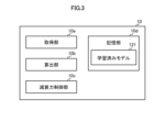
- FIG. 3 is a functional block diagram of an example control device for a vehicle according to the first embodiment.
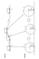
- FIG. 4A is an explanatory diagram for explaining deformation of a wheel of the vehicle according to the first embodiment.
- FIG. 4B is an explanatory diagram for explaining deformation of the wheel of the vehicle according to the first embodiment.
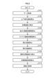
- FIG. 5 is a flowchart illustrating an example of a damping force control process executed by the control device according to the first embodiment.
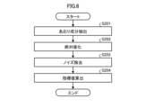
- FIG. 6 is a flowchart showing an example of a process for calculating an index value (tilt vibration index value) indicating the degree of tilt vibration in the damping force control process according to the first embodiment.
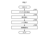
- FIG. 7 is a flowchart showing an example of a process for calculating an index value (rough vibration index value) indicating the degree of rough vibration in the damping force control process according to the first embodiment.
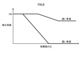
- FIG. 8 is a diagram illustrating an example of a map showing the relationship between the ratio of the thud vibration index value to the tilt vibration index value and the correction coefficient according to the first embodiment.
- FIG. 9 is a diagram showing another example of the map showing the relationship between the ratio of the thud vibration index value to the tilt vibration index value and the correction coefficient according to the first embodiment.
- FIG. 10 is a diagram showing an example of a map showing the relationship between the relative speed in the vertical direction of the vehicle body and the wheels, the target damping force, and the control stage of the shock absorber according to the first embodiment.
- FIG. 11 is a flowchart illustrating an example of a damping force control process executed by the control device according to the second embodiment.
- FIG. 12 is a flowchart illustrating an example of a damping force control process executed by the control device according to the third embodiment.
- FIG. 1 is a schematic diagram showing a schematic configuration of an example of a vehicle 1 according to the first embodiment.
- the vehicle 1 may be, for example, an automobile (internal combustion engine automobile) using an internal combustion engine (engine, not shown) as a driving source, an automobile (electric automobile, fuel cell automobile, etc.) using an electric motor (motor, not shown) as a driving source, or an automobile (hybrid automobile) using both of them as a driving source.
- the vehicle 1 may be equipped with various transmissions, and may be equipped with various devices (systems, parts, etc.) required to drive the internal combustion engine and the electric motor.
- the vehicle 1 is a four-wheeled vehicle (four-wheeled automobile) and has two front wheels 3F on the left and right and two rear wheels 3R on the left and right.
- the front (direction Fr) in the vehicle longitudinal direction is the left side.
- the vehicle control system 100 of the vehicle 1 includes a control device 10, a steering device 11, a steering sensor 12, a detection sensor 13, etc.
- the vehicle control system 100 also includes a suspension device 4, a rotation sensor 5, a torque sensor 6, etc. corresponding to each of the two front wheels 3F, and a suspension device 4, a rotation sensor 5, a torque sensor 6, etc. corresponding to each of the two rear wheels 3R.
- Fig. 2 is a schematic diagram showing the general configuration of an example of the suspension device 4 in the vehicle 1 according to the first embodiment.
- the part of the vehicle 1 on the vehicle body 2 side relative to the suspension device 4 is the sprung part 2a (Fig. 2)
- the part of the vehicle 1 on the wheel 3 side relative to the suspension device 4 is the unsprung part 2b (Fig. 2).
- vehicle 1 includes basic components other than those shown in Figures 1 and 2, but only the configuration related to vehicle control system 100 and the control related to that configuration will be described here.
- Wheels 3 are used as a general term for the two front wheels 3F and the two rear wheels 3R.
- the vertical relative speed which is the vertical speed of the wheels 3 of vehicle 1 relative to the body 2 of vehicle 1, is also referred to as stroke speed.
- the stroke speed is also the relative speed between the sprung portion 2a and the unsprung portion 2b.
- the control device 10 receives signals and data from each part of the vehicle control system 100 via a network such as a CAN (Controller Area Network), and controls each part of the vehicle control system 100 and executes various calculations.
- the control device 10 is an example of a damping force control device.
- the control device 10 is configured as a computer and includes an arithmetic processing unit (microcomputer, ECU (Electronic Control Unit), etc., not shown) and a memory unit 10d (e.g., ROM (Read Only Memory), RAM (Random Access Memory), flash memory, etc., see FIG. 3).
- the arithmetic processing unit reads out a program stored (installed) in the non-volatile memory unit 10d (e.g., ROM, flash memory, etc.), executes arithmetic processing according to the program, and functions (operates) as each part shown in FIG. 3.
- the memory unit 10d can store data (tables (data groups), functions, etc.) used in various calculations related to control, calculation results (including values during calculation), etc.
- the memory unit 10d also stores a trained model 121. Details of the trained model 121 will be described later.
- the steering device 11 includes, for example, a steering wheel, and steers (turns) the two front wheels 3F.
- the steering sensor 12 detects the steering angle (steering angle, turning angle, steering angle) of the front wheels 3F, and outputs steering angle data indicating the detected steering angle.
- the detection sensors 13 include a yaw rate sensor that detects the yaw rate of the vehicle 1 (body 2) and outputs the detected yaw rate, a longitudinal acceleration sensor that detects longitudinal acceleration, which is the acceleration of the vehicle 1 (body 2) in the longitudinal direction, and outputs the detected longitudinal acceleration, and a lateral acceleration sensor that detects lateral acceleration, which is the acceleration of the vehicle 1 (body 2) in the lateral direction (width direction), and outputs the detected lateral acceleration.
- a yaw rate sensor that detects the yaw rate of the vehicle 1 (body 2) and outputs the detected yaw rate
- a longitudinal acceleration sensor that detects longitudinal acceleration, which is the acceleration of the vehicle 1 (body 2) in the longitudinal direction, and outputs the detected longitudinal acceleration
- a lateral acceleration sensor that detects lateral acceleration, which is the acceleration of the vehicle 1 (body 2) in the lateral direction (width direction), and outputs the detected lateral acceleration.
- the rotation sensor 5 can output a signal corresponding to the speed (rotational speed, angular velocity, number of rotations, rotation state) of the rotation of each of the four wheels 3 in response to the rotation of each of the wheels.
- the control device 10 can calculate the speed of the vehicle 1 from the detection results of the rotation sensor 5. Note that a rotation sensor (not shown) that detects the rotation of the crankshaft, axles, etc. may be provided in addition to the rotation sensor 5 for the wheels 3, and the control device 10 may obtain the speed of the vehicle 1 from the detection results of this rotation sensor.
- the torque sensors 6 are provided for each of the four wheels 3 and detect the rotational torque input to each wheel 3.
- each of the above sensors is also used for operations (processing) performed by the vehicle 1 other than the damping force control processing described below.
- each sensor is not dedicated to the damping force control processing.
- FIG. 2 is a schematic diagram showing a schematic configuration of an example of a suspension device 4 in a vehicle according to the first embodiment.
- the suspension device 4 is interposed between the wheels 3 and the vehicle body 2, and suppresses the transmission of vibrations and shocks from the road surface to the vehicle body.
- the suspension device 4 has a coil spring 4a and a shock absorber 4b.
- the shock absorber 4b can electrically control (adjust) the damping force (damping characteristics).
- the shock absorber 4b has an actuator 4bb that operates based on an input current.
- the actuator 4bb can change the opening degree of an orifice provided in the piston of the shock absorber 4b, or change the opening degree between the valve body and the valve seat.
- the suspension device 4 is provided on each of the four wheels 3 (two front wheels 3F and two rear wheels 3R), and the control device 10 can control the damping force of each of the four wheels 3.
- the control device 10 can control the four wheels 3 so that they have different damping forces.
- the damping coefficient is controlled. More specifically, the damping coefficient is controlled by controlling the current flowing through the actuator 4bb of the shock absorber 4b.
- Each shock absorber 4b has multiple control stages.
- the multiple control stages are multiple stages ranging from the control stage (soft) with the smallest damping coefficient of the shock absorber 4b to the control stage (hard) with the largest damping coefficient Ci.
- vehicle control system 100 is merely an example, and can be modified in various ways.
- Publicly known devices can be used as the individual devices that make up the vehicle control system 100.
- each component of the vehicle control system 100 can be shared with other components.
- control device 10 can function (operate) as an acquisition unit 10a, a calculation unit 10b, a damping force control unit 10c, etc., as shown in FIG. 3, through the cooperation of hardware and software (programs).
- programs can include modules corresponding to each block shown in FIG. 3, except for the memory unit 10d.
- the acquisition unit 10a acquires a first physical quantity related to the motion of the vehicle 1 other than the acceleration in the vertical direction of the vehicle 1.
- the first physical quantity includes at least one of the following: the speed of the wheels 3 according to the rotation of the wheels 3, the acceleration in the longitudinal direction of the vehicle 1, the acceleration in the lateral direction of the vehicle 1, the yaw rate of the vehicle 1, the steering angle of the wheels 3, the steering angular velocity of the wheels 3, the rotational torque of the wheels 3, and the value of the current input to the shock absorber 4b according to the target damping coefficient.
- the speed of the wheels 3 includes at least one of the rotational speed of each of the multiple wheels 3, the difference between the rotational speeds of two wheels 3 arranged diagonally among the multiple wheels 3, and the difference between the rotational speeds of two wheels 3 arranged in the longitudinal direction of the vehicle 1.
- the acquisition unit 10a receives (acquires) the rotational speed of each wheel 3 from the rotation sensor 5.
- the acquisition unit 10a also calculates, or acquires, from the rotational speeds of the wheels 3, the difference between the rotational speeds of two wheels 3 arranged diagonally among the wheels 3 and the difference between the rotational speeds of two wheels 3 arranged in the longitudinal direction of the vehicle 1.
- the pair of two wheels 3 arranged diagonally is, for example, a pair of a right front wheel 3F and a left rear wheel 3R, and a pair of a left front wheel 3F and a right rear wheel 3R.
- the pair of two wheels 3 arranged in the longitudinal direction of the vehicle 1 is, for example, a pair of a right front wheel 3F and a right rear wheel 3R, and a pair of a left front wheel 3F and a left rear wheel 3R.
- the acquisition unit 10a also receives (acquires) the longitudinal acceleration of the vehicle 1 from the detection sensor 13.
- the acquisition unit 10a also acquires the lateral acceleration of the vehicle 1 from the detection sensor 13.
- the acquisition unit 10a also receives (acquires) the yaw rate of the vehicle 1 from the detection sensor 13.
- the acquisition unit 10a also receives (acquires) the steering angle of the wheels 3 and the steering angular speed of the wheels 3 from the steering sensor 12.
- the acquisition unit 10a also acquires the rotational torque of the wheels 3 from the torque sensor 6.
- the acquisition unit 10a also receives (acquires) the value of the current input to the shock absorber 4b according to the target damping coefficient from a current detection sensor (not shown).
- the calculation unit 10b receives as input predetermined data (hereinafter also referred to as input data) acquired by the acquisition unit 10a.
- the calculation unit 10b estimates (determines) a second physical quantity (output value) from the actual measurement value (input data) of the first physical quantity using a trained model 121 that inputs a first physical quantity related to the motion of the vehicle 1 other than the acceleration in the vertical direction of the vehicle 1 and outputs a second physical quantity related to the motion in the vertical direction of the vehicle 1.
- the calculation unit 10b calculates a target damping coefficient (damping coefficient) of the shock absorber 4b based on the estimated second physical quantity.
- the second physical quantity is, for example, a vertical relative speed (i.e., stroke speed) that is the relative speed in the vertical direction between the vehicle body 2 and the vehicle 1.
- the trained model 121 is configured, for example, by a neural network.
- the trained model 121 is configured to have been trained in advance to input a first physical quantity related to the motion of the vehicle 1 other than the acceleration in the vertical direction of the vehicle 1, and output (estimate) a second physical quantity related to the motion in the vertical direction of the vehicle 1.
- the neural network of the trained model 121 is configured by LSTM (Long short-term memory).
- the input data is the first physical quantity.
- the output data as teacher data is, for example, the actual measured value (true value) of the relative speed in the vertical direction of the wheels 3 of the vehicle body 2 and the vehicle 1, i.e., the stroke speed, measured by a stroke speed sensor (not shown).
- the damping force control unit 10c controls the damping force of the shock absorber 4b based on the calculated target damping coefficient. Specifically, the damping force control unit 10c determines the current value to be input to the shock absorber 4b based on the calculated target damping coefficient, and inputs the current value to the shock absorber 4b.
- Figs. 4A and 4B are explanatory diagrams for explaining the deformation of the wheel 3 of the vehicle 1 according to the first embodiment.
- Fig. 4A shows the vehicle 1 running on a road surface with an elevation difference.
- Fig. 4B shows the deformation of the wheel 3 of the vehicle 1 according to the shape of the road surface.
- the wheel 3 deforms according to the shape of the road surface, and thus the radius r of the wheel 3 deforms.
- Fig. 4B shows the deformation of the radius r of the wheel 3 from radius ra to radius rb via radius rb.
- the control device 10 controls the damping force of the shock absorber 4b by using the rotational speed of the wheel 3, as an example.
- FIG. 6 is a flowchart showing an example of the calculation process of an index value (sideways vibration index value) indicating the degree of sideways vibration in the damping force control process according to the first embodiment.
- FIG. 7 is a flowchart showing an example of the calculation process of an index value (thumping vibration index value) indicating the degree of thumping vibration in the damping force control process according to the first embodiment.
- FIG. 8 is a diagram showing an example of a map representing the relationship between the ratio of the thumping vibration index value to the sideways vibration index value and the correction coefficient according to the first embodiment.
- FIG. 9 is a diagram showing another example of a map representing the relationship between the ratio of the thumping vibration index value to the sideways vibration index value and the correction coefficient according to the first embodiment.
- FIG. 10 is a diagram showing an example of a map representing the relationship between the relative speed of the vehicle body and the wheels in the vertical direction, the target damping force, and the control stage of the shock absorber according to the first embodiment.
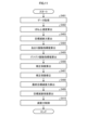
- FIG. 5 is a flowchart showing an example of the damping force control process executed by the control device 10 according to the first embodiment.
- the damping force control process shown in FIG. 5 is executed repeatedly at predetermined time intervals in a predetermined order, for example, for a plurality of wheels 3, when an ignition switch (not shown) is on.
- the control of the damping force may be simply referred to as control.
- the acquisition unit 10a acquires input data to be input to the trained model 121 (S101).
- the calculation unit 10b inputs the input data to the trained model 121 and calculates the vertical relative velocity Vrei, which is the vertical relative velocity between the vehicle body 2 and the vehicle 1, for each wheel 3 (S102). Specifically, the calculation unit 10b inputs the rotational speed of each wheel 3, the longitudinal acceleration of the vehicle 1, the lateral acceleration of the vehicle 1, the yaw rate of the vehicle 1, the steering angle of the wheel 3, the steering angular velocity of the wheel 3, the rotational torque of the wheel 3, and the value of the current input to the shock absorber 4b according to the target damping coefficient, into the trained model 121 and calculates each vertical relative velocity Vrei.
- the calculation unit 10b calculates the target damping force Fti of each shock absorber 4b based on the calculated vertical relative speed Vrei.
- the target damping force Fti is calculated based on the following formula (1).
- Csf in formula (1) is, for example, a damping coefficient of skyhook control.
- Csf may be a damping coefficient of any damping force control (for example, H ⁇ control) that improves the ride comfort of the vehicle 1 by damping vibration of the car body 2.
- Fti Csf ⁇ Vrei...(1)
- the calculation unit 10b calculates the tailgate vibration index value (I1i), which is an index value indicating the degree of tailgate vibration (first vibration) (S104).
- the tailgate vibration is, for example, a vibration in a frequency range in which the occupants of the vehicle 1 can feel a bouncy vibration of the vehicle body 18.
- the tailgate vibration is in the resonant frequency range of the vehicle body 2 in the sprung portion 2a.
- the resonant vibration frequency range of the vehicle body 2 is, for example, 1 to 2 Hz.
- the calculation unit 10b extracts the tilt component from the rotational speed of the wheel 3 acquired by the acquisition unit 10a (S201).
- the rotational speed of the wheel 3 includes at least one of (for example, all of) the rotational speed of each wheel 3, the difference between the rotational speeds of two wheels 3 arranged diagonally from the plurality of wheels 3, and the difference between the rotational speeds of two wheels 3 arranged in the front-rear direction of the vehicle 1.
- the rotational speed of the wheel 3 includes at least one of (for example, all of) the rotational speed of the wheel 3 (hereinafter also referred to as the first wheel 3) corresponding to the shock absorber 4b to be controlled, the difference between the rotational speeds of the wheel 3 arranged diagonally from the first wheel 3 and the first wheel 3, and the difference between the rotational speeds of the wheel 3 arranged in the front-rear direction of the vehicle 1 and the first wheel 3.
- the rotational speed of the wheel 3 is not limited to all of the above, and may be a part of it.
- the calculation unit 10b extracts the tilt component for each of the above rotational speeds (rotational speed, difference).
- the calculation unit 10b processes the signal indicating the wheel rotational speed with a high-pass filter having a predetermined cutoff frequency (e.g., 1 Hz), and further processes it with a low-pass filter having a predetermined cutoff frequency (e.g., 2 Hz).
- a tilt component Gz1i in a frequency range of, for example, 0.5 to 2 Hz is extracted as a first vibration component from the signal indicating the wheel rotational speed.
- the first vibration component is not limited to 0.5 to 2 Hz, and may be in another frequency range.
- the rotational speed of the wheel 3 is not limited to the above, and may be, for example, the difference between the rotational speeds of two wheels 3 arranged laterally.
- the calculation unit 10b converts the tilt component into an absolute value by full-wave rectifying the tilt component signal (S202). This converts the negative value of the tilt component signal into a positive value with the same absolute value.
- the calculation unit 10b removes a predetermined noise from the tilt component signal using a filter (S203).
- the calculation unit 10b calculates the maximum value of the tilt component converted into an absolute value within a preset time Tc (positive constant) up to the present as the tilt vibration index value (I1i) (S204). In this way, the calculation unit 10b calculates the tilt vibration index value (I1i) for each speed (rotation speed, difference) related to each rotation.
- the calculation unit 10b calculates a rugged vibration index value (I2i), which is an index value indicating the degree of rugged vibration (second vibration).
- Rugged vibration is vibration in a frequency range where occupants of the vehicle 1 feel a rugged ride.
- Rugged vibration is, for example, vibration in a frequency range (e.g., 6 to 10 Hz) between the resonant frequency range of the vehicle body 2 of the sprung portion 2a and the resonant frequency range of the wheels 3 and wheel carriers (not shown) of the unsprung portion 2b.
- a frequency range e.g., 6 to 10 Hz
- the above frequency range is not limited to the above.
- the lower limit of the above frequency range may be a value lower than 6 Hz as long as it is higher than the resonant frequency range of the unsprung portion 2b.
- the calculation unit 10b extracts the bumpy component from the speed related to the rotation of the wheel 3 acquired by the acquisition unit 10a (S301).
- the speed related to the rotation of the wheel 3 includes at least one of (for example, all of) the rotation speed of each wheel 3, the difference between the rotation speeds of two wheels 3 arranged diagonally among the multiple wheels 3, and the difference between the rotation speeds of two wheels 3 arranged in the front-rear direction of the vehicle 1, as in the case of extracting the tailwheel component.
- the speed related to the rotation of the wheel 3 includes at least one of (for example, all of) the rotation speed of the wheel 3 (hereinafter also referred to as the first wheel 3) corresponding to the shock absorber 4b to be controlled, the difference between the rotation speeds of the wheel 3 arranged diagonally to the first wheel 3 and the first wheel 3, and the difference between the rotation speeds of the wheel 3 arranged in the front-rear direction of the vehicle 1 to the first wheel 3 and the first wheel 3.
- the speed of the rotation of the wheel 3 is not limited to all of the above, and may be only a part of them.
- the calculation unit 10b extracts the roughness component for each of the above rotational speeds (rotational speed, difference).
- the calculation unit 10b processes the signal indicating the speed of the rotation of the wheel 3 with a high-pass filter having a predetermined cutoff frequency (6 Hz as an example), and further processes it with a low-pass filter having a predetermined cutoff frequency (10 Hz as an example).
- a roughness component (Gz2i) in a frequency range of, for example, 4 to 10 Hz is extracted as a second vibration component from the signal indicating the speed of the rotation of the wheel.
- the second frequency range is not limited to the above, and may be another frequency range.
- the speed of the rotation of the wheel 3 is not limited to the above, and may be, for example, the difference between the rotational speeds of two wheels 3 arranged laterally.
- the calculation unit 10b converts the rugged component into an absolute value by full-wave rectifying the signal of the rugged component (S302). As a result, the negative value of the signal of the rugged component is converted into a positive value with the same absolute value.
- the calculation unit 10b processes the absolute-valued signal of the rugged component with a low-pass filter having a cutoff frequency (e.g., 2 Hz) for removing high-frequency noise, and removes noise with frequencies higher than the frequency of the rugged component (S303).
- a cutoff frequency e.g. 2 Hz
- the calculation unit 10b calculates the maximum value of the ruggedness component, which has been converted to an absolute value and noise removed within a preset time Tc up to the present, as the ruggedness vibration index value (I2i) (S304). In this way, the calculation unit 10b calculates the ruggedness vibration index value (I2i) for each speed related to each rotation (rotation speed, difference). Please refer to JP-A-8-216646 for the calculation of the maximum values of the tilt component and ruggedness component.
- the calculation unit 10b calculates the correction coefficient (Kri) (S106). Specifically, the calculation unit 10b calculates the ratio (I2i/I1i) of the rough vibration index value (I2i) to the tilt vibration index value (I1i) for each rotation speed (rotation speed, difference). Then, the calculation unit 10b determines the ratio (I2i/I1i) with the largest value among the calculated ratios (I2i/I1i) as the ratio (I2i/I1i) of the rough vibration index value (I2i) to the final tilt vibration index value (I1i). Next, the calculation unit 10b calculates the correction coefficient (Kri) from the determined ratio I2i/I1i and the map shown in FIG. 8 or FIG. 9. FIG.
- the correction coefficient includes multiple stages.
- the calculation unit 10b sets the tilt vibration index value (I1i) to a preset constant greater than 0 and calculates the ratio (I2i/I1i).
- the preset constant is, for example, a positive value close to 0.
- the calculation unit 10b corrects the correction coefficient Kri (S107). Specifically, the calculation unit 10b applies low-pass filtering to the correction coefficient (Kri) to correct the correction coefficient (Kri) so that the rate of change of the correction coefficient (Kri) is limited.
- the limit on the rate of change of the correction coefficient (Kri) is not limited to the above, and may be realized by other means. Examples of other means include guarding the magnitude of the amount of change in the correction coefficient per unit time, performing moving average processing on the correction coefficient, and holding the correction coefficient at a constant value for a preset holding time.
- the means for limiting the rate of change of the correction coefficient Kri are similar to those for the correction coefficient in other embodiments described below.
- the calculation unit 10b calculates the target damping coefficient (Cti) of each shock absorber 4b (S109). Specifically, the calculation unit 10b determines the target control stage of each shock absorber 4b from the calculated vertical relative velocity (Vrei) and the calculated target damping force (Fti) and the map shown in FIG. 10. That is, the target damping coefficient (Cti) of each shock absorber 4b is calculated.
- the damping force control unit 10c controls the control stage of each shock absorber 4b so that the control stage becomes the target control stage calculated in step 210, thereby controlling the damping force.
- the damping force control unit 10c controls the damping coefficient (Ci) of each shock absorber 4b to the target damping coefficient (Cti), thereby controlling the damping force Fi to become the final target damping force Ffti.
- the vertical relative speed Vrei between each wheel 3 and the vehicle body 2 is calculated for each wheel 3 using the trained model 121.
- the target damping force Fti of each shock absorber 4b is generated based on the vertical relative speed Vrei.
- the sideways vibration index value I1i and the thumping vibration index value I2i are calculated based on the speed related to the rotation of the wheel 3. Note that the calculation of the sideways vibration index value I1i and the thumping vibration index value I2i is not limited to the above.
- the trained model 121 may be configured to output the vertical acceleration of the sprung portion 2a (vehicle body 2) in addition to the above output data based on the input of input data, and the sideways vibration index value I1i and the thumping vibration index value I2i may be extracted in a known direction from the vertical acceleration.
- a correction coefficient (Kri) is calculated based on the ratio (I2i/I1i) of the rough vibration index value (I2i) to the sideways vibration index value (I1i).
- the correction coefficient (Kri) is calculated so that it becomes smaller as the ratio (I2i/I1i) increases and becomes larger as the vehicle speed increases.
- the correction coefficient (Kri) is modified so that the rate of change is limited.
- the final target damping force (Ffti) is calculated as the product of the corrected correction coefficient (Kri) and the vertical relative velocity (Vrei).
- the damping force (Fi) of each shock absorber 4b is controlled to become the final target damping force (Ffti).
- the processes performed by the control device 10 include the following.
- the control device 10 estimates (calculates) the vertical relative velocity Vrei using the learned model 121.
- the control device 10 calculates the target damping force (Fti) from the vertical relative velocity (Vrei) and the damping coefficient (Csf).
- the control device 10 calculates the thudding vibration index value (I2i) and the sideways vibration index value (I1i) using the rotational speed of each wheel 3, the difference between the rotational speeds of the two diagonal wheels 3, and the difference between the rotational speeds of the two front-rear wheels 3.
- the control device 10 calculates the ratio (I2i/I1i) between the calculated rough vibration index value (I2i) and the tilt vibration index value (I1i). (e) The control device 10 selects the maximum value of the ratio between the determined rough vibration index value (I2i) and the determined swing vibration index value (I1i). (f) The control device 10 performs a hold process on the maximum value of the obtained ratio for a predetermined fixed period of time. (g) The control device 10 determines the correction coefficient (Kri) from the relationship between the held value and the vehicle speed.
- the control device 10 When the amount of change in the obtained correction coefficient (Kri) is equal to or greater than a threshold value, the control device 10 performs a change amount guard process (correction coefficient modification) to obtain a maximum amount of change. (i) The control device 10 calculates the final target damping force (Ftfi) from the obtained target damping force (Fti) and the maximum change amount. (j) The control device 10 calculates the target damping coefficient (Cti) from the determined final target damping force (Ftfi) and executes damping force control.
- a change amount guard process correction coefficient modification
- the control device 10 determines whether or not the road surface has a larger rugged vibration index value (I2i) compared to the sideways vibration index value (I1i), and if it determines that the road surface has a larger rugged vibration index value (I2i) compared to the sideways vibration index value (I1i), it can perform control to reduce the damping force.
- the control device 10 controls the shock absorber 4b interposed between the wheel 3 of the vehicle 1 and the body 2 of the vehicle 1.
- the control device 10 includes a calculation unit 10b and a damping force control unit 10c.
- the calculation unit 10b estimates a second physical quantity from an actual measurement value of the first physical quantity using a trained model 121 that inputs a first physical quantity related to the motion of the vehicle 1 other than the acceleration in the vertical direction of the vehicle 1 and outputs a second physical quantity related to the motion in the vertical direction of the vehicle 1, and calculates a target damping coefficient of the shock absorber 4b based on the estimated second physical quantity.
- the damping force control unit 10c controls the damping force of the shock absorber 4b based on the calculated target damping coefficient.
- the calculation unit 10b uses the trained model 121 to calculate the target damping coefficient of the shock absorber 4b from the actual measured value of the first physical quantity related to the motion of the vehicle 1 other than the vertical acceleration of the vehicle 1, so there is no need to provide the vehicle 1 with a dedicated vertical acceleration sensor for controlling the damping force of the shock absorber 4b. Therefore, it is possible to prevent the structure of the vehicle 1 from becoming complicated in order to control the damping force of the shock absorber 4b.
- the first physical quantity also includes at least one of the following: the speed of the wheel 3 according to the rotation of the wheel 3, the longitudinal acceleration of the vehicle 1, the lateral acceleration of the vehicle 1, the yaw rate of the vehicle 1, the steering angle of the wheel 3, the steering angular velocity of the wheel 3, the rotational torque of the wheel 3, and the value of the current input to the shock absorber 4b according to the target damping coefficient.
- the target damping coefficient can be calculated from at least one of the speed of the wheel 3, the longitudinal acceleration of the vehicle 1, the lateral acceleration of the vehicle 1, the yaw rate of the vehicle 1, the steering angle of the wheel 3, the steering angular velocity of the wheel 3, the rotational torque of the wheel 3, and the value of the current input to the shock absorber 4b according to the target damping coefficient.
- the calculation unit 10b also calculates the target damping coefficient of the shock absorber 4b based on the estimated second physical quantity and the speed of the wheels 3.
- the speed of the wheels 3 includes at least one of the rotational speeds of each of the multiple wheels 3, the difference between the rotational speeds of two wheels 3 arranged diagonally among the multiple wheels 3, and the difference between the rotational speeds of two wheels arranged in the front-rear direction of the vehicle 1.
- a more appropriate target damping coefficient can be calculated when the speed of the wheels 3 includes at least one of the difference in the rotational speeds of two wheels 3 arranged diagonally on the wheel 3 and the difference in the rotational speeds of two wheels 3 arranged in the front-rear direction of the vehicle 1.
- FIG. 11 is a flowchart illustrating an example of a damping force control process executed by the control device according to the second embodiment.
- This embodiment differs from the first embodiment in that the second physical quantity related to the vertical movement of the vehicle 1 output by the trained model 121 is the sprung velocity, which is the velocity of the sprung part 2a (vehicle body 2), and in the damping force control process executed by the control device 10.
- the calculation unit 10b inputs the input data to the trained model 121 and calculates the sprung velocity Vz, which is the velocity of the sprung portion 2a (vehicle body 2), for each wheel 3. Specifically, the calculation unit 10b inputs the rotational speed of each wheel 3, the longitudinal acceleration of the vehicle 1, the lateral acceleration of the vehicle 1, the yaw rate of the vehicle 1, the steering angle of the wheel 3, the steering angular velocity of the wheel 3, the rotational torque of the wheel 3, and the value of the current input to the shock absorber 4b according to the target damping coefficient, to the trained model 121 to calculate the sprung velocity Vz.
- the calculation unit 10b calculates the target damping force Fti of each shock absorber 4b based on the calculated sprung velocity Vz.
- the target damping force Fti is calculated based on the following formula (3).
- Fti Csf ⁇ Vz...(3)
- FIG. 12 is a flowchart illustrating an example of a damping force control process executed by the control device according to the third embodiment.
- the damping force control process executed by the control device 10 differs from that of the first embodiment.
- the damping force control process of this embodiment is performed alternately for, for example, the two front wheels 3 and the two rear wheels 3 according to the flowchart shown in FIG. 12.
- S501 to S505, S509, and S510 are similar to S101 to S105, S109, and S110 in the first embodiment. Then, instead of S106 to S108 in the first embodiment, S506 to S508 are executed, respectively.
- the larger of the sideways vibration index values I1FL, I1FR corresponding to the two front wheels 3 is set as the sideways vibration index value I1fr of the vehicle body 2 at the position corresponding to the two front wheels 3.
- the larger of the sideways vibration index values I1RL and I1RR corresponding to the two rear wheels 3 is set as the sideways vibration index value I1re of the vehicle body 2 at the position corresponding to the two rear wheels 3.
- the larger of the thumping vibration index values I2FL and I2FR corresponding to the two front wheels 3 is set as the thumping vibration index value I2fr of the vehicle body 18 at the position corresponding to the two front wheels 3.
- the larger of the thumping vibration index values I2RL and I2RR corresponding to the two rear wheels 3 is set as the thumping vibration index value I2re of the vehicle body 18 at the position corresponding to the two rear wheels 3.
- the ratios I2fr/I1fr and I2re/I1re of the thumping vibration index values I2fr and I2re to the sideways vibration index values I1fr and I1re, respectively, are calculated. Furthermore, based on the ratios I2fr/I1fr and I2re/I1re, the maps shown in FIG. 8 or FIG. 9 are referenced to calculate the correction coefficients Krfr and Krre for the two front wheels 3 and the two rear wheels 3, respectively.
- the correction coefficients Krfr and Krre are low-pass filtered to modify the correction coefficients Krfr and Krre so that the rate of change is limited.
- the final target damping force Ffti of each shock absorber 4b is calculated using the revised correction coefficients Krfr and Krre according to the following equations (4) to (7).
- FftFL Krfr ⁇ FtFL...(4)
- FftFR Krfr ⁇ FtFR...(5)
- FftRL Krre ⁇ FtRL...(6)
- FftRR Krre ⁇ FtRR...(7)
- the programs for implementing the functions of the above-described embodiments on a computer may be provided by recording them in an installable or executable format on a computer-readable recording medium such as a CD-ROM, a flexible disk (FD), a CD-R, or a digital versatile disk (DVD).
- a computer-readable recording medium such as a CD-ROM, a flexible disk (FD), a CD-R, or a digital versatile disk (DVD).
- the program may also be configured to be stored on a computer connected to a network such as the Internet and provided by being downloaded via the network.
- the program may also be configured to be provided or distributed via a network such as the Internet.
- the second physical quantity output by the trained model 121 is not limited to those described in the above embodiment.
- the second physical quantity may be the roll angular velocity of the vehicle 1 (body 2), the pitch angular velocity of the vehicle 1 (body 2), the heave velocity of the vehicle 1 (body 2), etc.
- the damping force control device (10) of the present embodiment has at least the following configuration. That is, the damping force control device (10) is a damping force control device (10) that controls a shock absorber (4b) interposed between the wheels (3) of a vehicle (1) and the body (2) of the vehicle (1), and includes a calculation unit (10b) that utilizes a learned model (121) that inputs a first physical quantity related to the movement of the vehicle (1) other than the vertical acceleration of the vehicle (1) and outputs a second physical quantity related to the vertical movement of the vehicle (1) to estimate a second physical quantity from an actual measured value of the first physical quantity and calculates a target damping coefficient of the shock absorber (4b) based on the estimated second physical quantity, and a damping force control unit (10c) that controls the damping force of the shock absorber (4b) based on the calculated target damping coefficient.
- a learned model (121) that inputs a first physical quantity related to the movement of the vehicle (1) other than the vertical acceleration of the vehicle (1) and outputs a second physical quantity related to the vertical movement
- the calculation unit (10b) uses the trained model (121) to calculate the target damping coefficient of the shock absorber (4b) from the actual measured value of the first physical quantity related to the motion of the vehicle (1) other than the vertical acceleration of the vehicle (1), so there is no need to provide the vehicle (1) with a dedicated vertical acceleration sensor for controlling the damping force of the shock absorber (4b). Therefore, it is possible to prevent the structure of the vehicle (1) from becoming complicated in order to control the damping force of the shock absorber (4b).
- the first physical quantity includes at least one of the following: a speed of the wheel (3) according to the rotation of the wheel (3), a longitudinal acceleration of the vehicle (1), a lateral acceleration of the vehicle (1), a yaw rate of the vehicle (1), a steering angle of the wheel (3), a steering angular velocity of the wheel (3), a rotational torque of the wheel (3), and a value of a current input to the shock absorber (4b) according to the target damping coefficient.
- the target damping coefficient can be calculated from at least one of the speed of the wheel (3), the longitudinal acceleration of the vehicle (1), the lateral acceleration of the vehicle (1), the yaw rate of the vehicle (1), the steering angle of the wheel (3), the steering angular velocity of the wheel (3), the rotational torque of the wheel (3), and the value of the current input to the shock absorber (4b) according to the target damping coefficient.
- the calculation unit (10b) also calculates a target damping coefficient for the shock absorber (4b) based on the estimated second physical quantity and the speed of the wheels (3), and it is preferable that the speed of the wheels (3) includes at least one of the rotational speeds of each of the multiple wheels (3), the difference between the rotational speeds of two wheels (3) arranged diagonally among the multiple wheels (3), and the difference between the rotational speeds of two wheels (3) arranged in the fore-and-aft direction of the vehicle (1).
- a more appropriate target damping coefficient can be calculated when the speed of the wheels (3) includes at least one of the following: the difference between the rotational speeds of two wheels (3) arranged diagonally around the wheels (3) and the difference between the rotational speeds of two wheels (3) arranged in the fore-and-aft direction of the vehicle (1).
Landscapes
- Engineering & Computer Science (AREA)
- Mechanical Engineering (AREA)
- Vehicle Body Suspensions (AREA)
Abstract
減衰力制御装置は、車両の上下方向の加速度以外の車両の運動に関する第1の物理量を入力して車両の上下方向の運動に関わる第2の物理量を出力する学習済みモデルを利用して、第1の物理量の実測値から第2の物理量を推定し、推定した第2の物理量に基づいて、ショックアブソーバの目標減衰係数を算出する算出部と、算出された目標減衰係数に基づいて、ショックアブソーバの減衰力を制御する減衰力制御部と、を備える。
Description
本発明の実施形態は、減衰力制御装置に関する。
車両に設けられ、サスペンションのショックアブソーバの減衰力を制御し、乗り心地の向上や走行安定性の向上を図ることができる減衰力制御装置がある。この種の減衰力制御装置として、例えば、車両に搭載された上下加速度センサの出力値に基づいて、車両の上下方向の振動における中周波成分と低周波成分との比率を算出し、当該比率に基づいてショックアブソーバの減衰力を制御する減衰力制御装置が知られている(例えば、特許文献1参照)。
上記従来技術では、ショックアブソーバの減衰力の制御のための専用の上下加速度センサを車両に設けるため、車両の構造が複雑化するという問題がある。
本発明の実施形態が解決しようとする課題の一つは、ショックアブソーバの減衰力を制御する上で車両の構造が複雑化するのを抑制することが可能な減衰力制御装置を得ることである。
本発明の実施形態の減衰力制御装置は、車両の車輪と前記車両の車体との間に介在するショックアブソーバを制御する減衰力制御装置であって、前記車両の上下方向の加速度以外の前記車両の運動に関する第1の物理量を入力して前記車両の上下方向の運動に関わる第2の物理量を出力する学習済みモデルを利用して、前記第1の物理量の実測値から前記第2の物理量を推定し、推定した前記第2の物理量に基づいて、前記ショックアブソーバの目標減衰係数を算出する算出部と、算出された前記目標減衰係数に基づいて、前記ショックアブソーバの減衰力を制御する減衰力制御部と、を備える。
本発明の実施形態の減衰力制御装置によれば、算出部が、学習済みモデルを利用して、車両の上下方向の加速度以外の車両の運動に関する第1の物理量の実測値からショックアブソーバの目標減衰係数を算出するので、ショックアブソーバの減衰力の制御のための専用の上下加速度センサを車両に設ける必要がない。よって、ショックアブソーバの減衰力を制御する上で車両の構造が複雑化するのを抑制することができる。
以下に図面を参照して実施形態について詳細に説明する。なお、この実施形態により本発明が限定されるものではない。以下の複数の実施形態には、同様の構成要素が含まれている。それら同様の構成要素には共通の符号が付与されるとともに、重複する説明が省略される。
<第1の実施形態>
図1は、第1の実施形態にかかる車両1の一例の概略構成を示す模式図である。本実施形態では、車両1は、例えば、内燃機関(エンジン、図示されず)を駆動源とする自動車(内燃機関自動車)であってもよいし、電動機(モータ、図示されず)を駆動源とする自動車(電気自動車、燃料電池自動車等)であってもよいし、それらの双方を駆動源とする自動車(ハイブリッド自動車)であってもよい。また、車両1は、種々の変速装置を搭載することができるし、内燃機関や電動機を駆動するのに必要な種々の装置(システム、部品等)を搭載することができる。また、車両1における車輪3の駆動に関わる装置の方式や、数、レイアウト等は、種々に設定することができる。また、本実施形態では、一例として、車両1は、四輪車(四輪自動車)であり、左右二つの前輪3Fと、左右二つの後輪3Rとを有する。なお、図1では、車両前後方向の前方(方向Fr)は、左側である。
図1は、第1の実施形態にかかる車両1の一例の概略構成を示す模式図である。本実施形態では、車両1は、例えば、内燃機関(エンジン、図示されず)を駆動源とする自動車(内燃機関自動車)であってもよいし、電動機(モータ、図示されず)を駆動源とする自動車(電気自動車、燃料電池自動車等)であってもよいし、それらの双方を駆動源とする自動車(ハイブリッド自動車)であってもよい。また、車両1は、種々の変速装置を搭載することができるし、内燃機関や電動機を駆動するのに必要な種々の装置(システム、部品等)を搭載することができる。また、車両1における車輪3の駆動に関わる装置の方式や、数、レイアウト等は、種々に設定することができる。また、本実施形態では、一例として、車両1は、四輪車(四輪自動車)であり、左右二つの前輪3Fと、左右二つの後輪3Rとを有する。なお、図1では、車両前後方向の前方(方向Fr)は、左側である。
本実施形態では、一例として、車両1の車両制御システム100は、制御装置10や、操舵装置11、操舵センサ12、検出センサ13、等を備える。また、車両制御システム100は、二つの前輪3Fのそれぞれに対応して、懸架装置4や、回転センサ5、トルクセンサ6等を備えるとともに、二つの後輪3Rのそれぞれに対応して、懸架装置4、回転センサ5、トルクセンサ6等を備えている。
図2は、第1の実施形態にかかる車両1における懸架装置4の一例の概略構成を示す模式図である。図2に示されるように、懸架装置4に対して車体2側の車両1の部分は、ばね上部2a(図2)であり、懸架装置4に対して車輪3側の車両1の部分は、ばね下部2b(図2)である。
なお、車両1は、図1および図2の他にも車両1としての基本的な構成要素を備えているが、ここでは、車両制御システム100に関わる構成ならびに当該構成に関わる制御についてのみ、説明される。また、二つの前輪3Fと二つの後輪3Rとの総称として、車輪3を用いる。また、車両1の車体2に対する車両1の車輪3の上下方向の相対速度である上下方向相対速度をストローク速度とも称する。当該ストローク速度は、ばね上部2aとばね下部2bとの相対速度でもある。
制御装置10は、車両制御システム100の各部からCAN(Controller Area Network)等のネットワークを介して信号やデータ等を受け取るとともに、車両制御システム100の各部の制御や各種の演算を実行する。本実施形態では、制御装置10は、減衰力制御装置の一例である。また、制御装置10は、コンピュータとして構成されており、演算処理部(マイクロコンピュータ、ECU(Electronic Control Unit)等、図示されず)や記憶部10d(例えば、ROM(Read Only Memory)、RAM(Random Access Memory)、フラッシュメモリ等、図3参照)等を備えている。演算処理部は、不揮発性の記憶部10d(例えばROMや、フラッシュメモリ等)に記憶された(インストールされた)プログラムを読み出し、当該プログラムにしたがって演算処理を実行し、図3に示された各部として機能(動作)することができる。また、記憶部10dには、制御に関わる各種演算で用いられるデータ(テーブル(データ群)や、関数等)、演算結果(演算途中の値も含む)等が記憶されうる。また、記憶部10dには、学習済みモデル121が記憶されている。学習済みモデル121の詳細は、後述する。
操舵装置11は、例えば、ハンドルを含み、二つの前輪3Fを操舵(転舵)する。操舵センサ12は、前輪3Fの操舵角度(舵角、切れ角、転舵角)を検出して、検出した操舵角度を示す操舵角度データを出力する。
検出センサ13は、車両1(車体2)のヨーレートを検出し、検出したヨーレートを出力するヨーレートセンサ、車両1(車体2)の前後方向の加速度である前後方向加速度を検出し、検出した前後方向加速度を出力する前後方向加速度センサ、および車両1(車体2)の横方向(幅方向)の加速度である横方向加速度を検出し、検出した横方向加速度を出力する横方向加速度センサを含む。
回転センサ5は、四つの車輪3のそれぞれの回転に応じて各車輪の回転に関する速度(回転速度、角速度、回転数、回転状態)に応じた信号を出力することができる。制御装置10は、回転センサ5の検出結果から、車両1の速度を算出することができる。なお、車輪3用の回転センサ5とは別に、クランクシャフトや車軸等の回転を検出する回転センサ(図示されず)が設けられてもよく、制御装置10は、この回転センサの検出結果から車両1の速度を取得してもよい。
トルクセンサ6は、四つの車輪3のそれぞれに対応して設けられ、各車輪3に入力される回転トルクを検出する。
上記の各センサの出力は、車両1が実行する動作(処理)のうち後述する減衰力制御処理以外の他の動作にも利用される。すなわち、各センサは、減衰力制御処理専用のものではない。
図2は、第1の実施形態にかかる車両における懸架装置4の一例の概略構成が示された模式図である。図2に示されるように、懸架装置4は、車輪3と車体2との間に介在され、路面からの振動や衝撃が車体に伝達されるのを抑制する。懸架装置4は、コイルばね4aと、ショックアブソーバ4bと、を有する。ショックアブソーバ4bは、減衰力(減衰特性)を電気的に制御(調整)可能である。具体的には、ショックアブソーバ4bは、入力される電流に基づいて動作するアクチュエータ4bbを有する。アクチュエータ4bbは、ショックアブソーバ4bのピストンに設けられるオリフィスの開口度を変更したり、弁体と弁座との間の開口度を変更したりすることができる。これにより、ショックアブソーバ4b内でピストンにより仕切られた2つの油室の間を流通する潤滑油の流通量を制御して、ショックアブソーバ4bの減衰力が調整される。懸架装置4は、四つの車輪3(二つの前輪3Fおよび二つの後輪3R)のそれぞれに設けられており、制御装置10は、四つの車輪3のそれぞれの減衰力を制御することができる。制御装置10は、四つの車輪3を、互いに減衰力が異なる状態に制御することができる。詳細には、各ショックアブソーバ4bの減衰力(=減衰係数×ストローク速度)を制御するためには、減衰係数を制御することとなる。より詳細には、ショックアブソーバ4bのアクチュエータ4bbに流す電流を制御することで減衰係数を制御する。
各ショックアブソーバ4bは、複数の制御段を有している。複数の制御段は、ショックアブソーバ4bの減衰係数が最も小さい制御段(ソフト)から減衰係数Ciが最も大きい制御段(ハード)までの複数の段階の制御段である。
なお、上述した車両制御システム100の構成はあくまで一例であって、種々に変更して実施することができる。車両制御システム100を構成する個々の装置としては、公知の装置を用いることができる。また、車両制御システム100の各構成は、他の構成と共用することができる。
制御装置10は、具体的には、一例として、ハードウエアとソフトウエア(プログラム)との協働により、図3に示されるような、取得部10aや、算出部10b、減衰力制御部10c等として機能(動作)することができる。すなわち、プログラムには、一例としては、図3に示される記憶部10dを除く各ブロックに対応したモジュールが含まれうる。
取得部10aは、車両1の上下方向の加速度以外の車両1の運動に関する第1の物理量を取得する。例えば、第1の物理量は、車輪3の回転に応じた車輪3に関する速度と、車両1の前後方向の加速度と、車両1の横方向の加速度と、車両1のヨーレートと、車輪3の舵角と、車輪3の舵角速度と、車輪3の回転トルクと、目標減衰係数に応じてショックアブソーバ4bに入力される電流の値とのうちの少なくとも一つを含む。また、車輪3に関する速度は、複数の車輪3のそれぞれの回転速度と、複数の車輪3の対角方向に並ぶ二つの車輪3の回転速度の差分と、車両1の前後方向に並ぶ二つの車輪3の回転速度の差分とのうちの少なくとも一つを含む。
具体的には、取得部10aは、各車輪3のそれぞれの回転速度を回転センサ5から受信(取得)する。また、取得部10aは、複数の車輪3のそれぞれの回転速度から、複数の車輪3の対角方向に並ぶ二つの車輪3の回転速度の差分と、車両1の前後方向に並ぶ二つの車輪3の回転速度の差分とを算出すなわち取得する。対角方向に並ぶ二つの車輪3の組は、例えば、右側の前輪3Fおよび左側の後輪3Rの組みと、左側の前輪3Fおよび右側の後輪3Rの組みとである。また、車両1の前後方向に並ぶ二つの車輪3の組は、例えば、右側の前輪3Fおよび右側の後輪3Rの組みと、左側の前輪3Fおよび左側の後輪3Rの組みとである。また、取得部10aは、車両1の前後方向の加速度を検出センサ13から受信(取得)する。また、取得部10aは、車両1の横方向の加速度を検出センサ13から取得する。また、取得部10aは、車両1のヨーレートを検出センサ13から受信(取得)する。また、取得部10aは、車輪3の舵角および車輪3の舵角速度を操舵センサ12から受信(取得)する。また、取得部10aは、車輪3の回転トルクをトルクセンサ6から取得する。また、取得部10aは、目標減衰係数に応じてショックアブソーバ4bに入力される電流の値を電流検出センサ(不図示)から受信(取得)する。
算出部10bは、一例として、取得部10aによって取得された所定のデータ(以後、入力データとも称する)が入力される。算出部10bは、車両1の上下方向の加速度以外の車両1の運動に関する第1の物理量を入力して車両1の上下方向の運動に関わる第2の物理量を出力する学習済みモデル121を利用して、第1の物理量の実測値(入力データ)から第2の物理量(出力値)を推定する(求める)。算出部10bは、推定した第2の物理量に基づいて、ショックアブソーバ4bの目標減衰係数(減衰係数)を算出する。第2の物理量は、例えば、車体2と車両1との上下方向の相対速度である上下相対速度(すなわちストローク速度)である。
学習済みモデル121は、例えば、ニューラルネットワークによって構成されている。学習済みモデル121は、車両1の上下方向の加速度以外の車両1の運動に関する第1の物理量を入力して車両1の上下方向の運動に関わる第2の物理量を出力(推定)するようにうに予め学習を行った構成である。例えば、学習済みモデル121のニューラルネットワークは、LSTM(Long short‐term memory)によって構成される。学習済みモデル121の学習時において、入力データは、第1の物理量である。教師データとしての出力データは、例えば、ストローク速度センサ(不図示)で計測された車体2と車両1との車輪3の上下方向の相対速度すなわちストローク速度の実測値(真値)である。
減衰力制御部10cは、算出された目標減衰係数に基づいて、ショックアブソーバ4bの減衰力を制御する。具体的には、減衰力制御部10cは、算出された目標減衰係数に基づいて、ショックアブソーバ4bに入力する電流値を決定し、該電流値をショックアブソーバ4bに入力する。
ここで、図4A、図4Bは、第1の実施形態にかかる車両1の車輪3の変形を説明するための説明図である。図4Aには、車両1が高低差のある路面上を走行する様子が示されている。図4Bには、上記路面の形状に応じて車両1の車輪3が変形する様子が示されている。図4A、図4Bに示されるように、路面の形状に応じて車輪3が変形することにより、車輪3の半径rが変形する。一例として、図4Bには、車輪3の半径rが、半径raから半径rbを経て半径rbに変形する様子が示されている。このように車輪3の半径が変形することで、車輪3の回転速度が変化する。本実施形態では、制御装置10は、一例として、車輪3の回転速度を用いて、ショックアブソーバ4bの減衰力を制御する。
次に、制御装置10が実行する減衰力制御処理の一例を説明する。図6は、第1の実施形態にかかる減衰力制御処理におけるあおり振動の度合いを示す指標値(あおり振動指標値)の算出処理の一例を示すフローチャートである。図7は、第1の実施形態にかかる減衰力制御処理におけるゴツゴツ振動の度合いを示す指標値(ゴツゴツ振動指標値)の算出処理の一例を示すフローチャートである。図8は、第1の実施形態にかかるあおり振動指標値に対するゴツゴツ振動指標値の比と、補正係数との関係を表すマップの一例を示す図である。図9は、第1の実施形態にかかるあおり振動指標値に対するゴツゴツ振動指標値の比と、補正係数との関係を表すマップの別の一例を示す図である。図10は、第1の実施形態にかかる車体および車輪の上下方向の相対速度と、目標減衰力と、ショックアブソーバの制御段との関係を表すマップの一例を示す図である。
図5は、第1の実施形態にかかる制御装置10が実行する減衰力制御処理の一例を示すフローチャートである。図5に示される減衰力制御処理は、イグニッションスイッチ(不図示)がオンであるときに、例えば複数の車輪3に対して所定の順に所定の時間毎に繰返し実行される。なお、以下の説明においては、減衰力の制御を単に制御と称する場合がある。
まず、取得部10aが、学習済みモデル121に入力する入力データを取得する(S101)。
次に、算出部10bが、入力データを学習済みモデル121に入力して、車体2と車両1との上下方向の相対速度である上下相対速度Vreiを各車輪3ごとに算出する(S102)。具体的には、算出部10bは、各車輪3の回転速度と、車両1の前後方向の加速度と、車両1の横方向の加速度と、車両1のヨーレートと、車輪3の舵角と、車輪3の舵角速度と、車輪3の回転トルクと、目標減衰係数に応じてショックアブソーバ4bに入力される電流の値とを、学習済みモデル121に入力して、上下相対速度Vreiごとに算出する。
次に、算出部10bは、算出した上下相対速度Vreiに基づいて、各ショックアブソーバ4bのそれぞれの目標減衰力Ftiを算出する。目標減衰力Ftiは、下記の式(1)に基づいて算出される。式(1)のCsfは、例えば、スカイフック制御の減衰係数である。なお、Csfは、車体2の振動を減衰させて車両1の乗り心地性を向上させる任意の減衰力制御(例えばH∞制御)の減衰係数であってよい。
Fti=Csf×Vrei ・・・(1)
Fti=Csf×Vrei ・・・(1)
次に、算出部10bは、あおり振動(第1の振動)の度合を示す指標値であるあおり振動指標値(I1i)を算出する(S104)。あおり振動は、例えば、車両1の乗員が車体18のフワフワとした振動を感じ得る周波数域の振動である。一例として、あおり振動は、ばね上部2aにおける車体2の共振周波数域である。車体2の共振振動周波数域は、例えば、1~2Hzである。
S104の処理について、図6に示されるフローチャートを参照して詳しく説明する。図6に示されるように、算出部10bは、取得部10aによって取得された車輪3の回転に関する速度に対してあおり成分の抽出を行う(S201)。詳細には、車輪3の回転に関する速度は、例えば、各車輪3のそれぞれの回転速度と、複数の車輪3の対角方向に並ぶ二つの車輪3の回転速度の差分と、車両1の前後方向に並ぶ二つの車輪3の回転速度の差分との少なくとも一つ(一例として全部)を含む。より詳細には、車輪3の回転に関する速度は、制御対象のショックアブソーバ4bに対応する車輪3(以後、第1の車輪3とも称する)の回転速度と、第1の車輪3に対して対角方向に並ぶ車輪3と第1の車輪3との回転速度の差分と、第1の車輪3に対して車両1の前後方向に並ぶ車輪3と、第1の車輪3との回転速度の差分と、の少なくとも一つ(一例として全部)を含む。なお、車輪3の回転に関する速度は、上記のうち全部に限られず一部であってもよい。算出部10bは、上記の各回転に関する速度(回転速度、差分)について、それぞれ、あおり成分の抽出を行う。具体的には、算出部10bは、車輪の回転に関する速度を示す信号を、所定(例えば1Hz)のカットオフ周波数を有するハイパスフィルタによって処理し、更に所定(例えば2Hz)のカットオフ周波数を有するローパスフィルタにて処理する。これにより、車輪の回転に関する速度を示す信号から第1の振動の成分として例えば0.5~2Hzの周波数域のあおり成分Gz1iが抽出される。なお、上記第1の振動の成分は、0.5~2Hzに限定されず、他の周波数域であってもよい。また、車輪3の回転に関する速度は、上記に限定されず、例えば、車輪3の横方向に並ぶ二つの車輪3の回転速度の差分であってもよい。
次に、算出部10bは、あおり成分の信号を全波整流することにより、あおり成分を絶対値化する(S202)。これにより、あおり成分の信号の負の値が、絶対値が同一で正の値に転換される。次に、算出部10bは、フィルタによってあおり成分の信号の所定のノイズを除去する(S203)。次に、算出部10bは、現在までの予め設定された時間Tc(正の定数)内に絶対値化されたあおり成分の最大値を、あおり振動指標値(I1i)として算出する(S204)。このようにして、算出部10bは、各回転に関する速度(回転速度、差分)について、それぞれ、あおり振動指標値(I1i)を算出する。
図5に戻って、算出部10bは、ゴツゴツ振動(第2の振動)の度合を示す指標値であるゴツゴツ振動指標値(I2i)を算出する。ゴツゴツ振動は、車両1の乗員がゴツゴツとした乗り心地を感じる周波数域の振動である。ゴツゴツ振動は、例えば、ばね上部2aの車体2の共振周波数域と、ばね下部2bの車輪3および車輪キャリア(不図示)等の共振周波数域との間の周波数域(例えば、6~10Hz)の振動である。なお、上記周波数域は、上記に限定されない。例えば、上記周波数域の下限は、ばね下部2bの共振周波数域よりも高ければ、6Hzよりも低い値であってもよい。
S105の処理について、図7に示されるフローチャートを参照して詳しく説明する。図7に示されるように、算出部10bは、取得部10aによって取得された車輪3の回転に関する速度に対してゴツゴツ成分の抽出を行う(S301)。詳細には、車輪3の回転に関する速度は、あおり成分の抽出の場合と同様に、例えば、各車輪3のそれぞれの回転速度と、複数の車輪3の対角方向に並ぶ二つの車輪3の回転速度の差分と、車両1の前後方向に並ぶ二つの車輪3の回転速度の差分との少なくとも一つ(一例として全部)を含む。より詳細には、車輪3の回転に関する速度は、制御対象のショックアブソーバ4bに対応する車輪3(以後、第1の車輪3とも称する)の回転速度と、第1の車輪3に対して対角方向に並ぶ車輪3と第1の車輪3との回転速度の差分と、第1の車輪3に対して車両1の前後方向に並ぶ車輪3と、第1の車輪3との回転速度の差分と、の少なくとも一つ(一例として全部)を含む。なお、車輪3の回転に関する速度は、上記のうち全部に限られず一部であってもよい。算出部10bは、上記の各回転に関する速度(回転速度、差分)に対して、それぞれ、ゴツゴツ成分の抽出を行う。具体的には、算出部10bは、車輪3の回転に関する速度を示す信号を、所定(一例として6Hz)のカットオフ周波数を有するハイパスフィルタにて処理し、更に所定(一例として10Hz)のカットオフ周波数を有するローパスフィルタにて処理する。これにより、車輪の回転に関する速度を示す信号からから第2の振動の成分として例えば4~10Hzの周波数域のゴツゴツ成分(Gz2i)が抽出される。なお、上記第2の周波数域は上記に限定されず、他の周波数域であってもよい。また、車輪3の回転に関する速度は、上記に限定されず、例えば、車輪3の横方向に並ぶ二つの車輪3の回転速度の差分であってもよい。
次に算出部10bは、ゴツゴツ成分の信号を全波整流することにより、ゴツゴツ成分を絶対値化する(S302)。これにより、ゴツゴツ成分の信号の負の値が、絶対値が同一で正の値に転換される。
次に、算出部10bは、絶対値化されたゴツゴツ成分の信号を、高周波ノイズを除去するためのカットオフ周波数(例えば2Hz)を有するローパスフィルタにて処理し、ゴツゴツ成分の周波数よりも高い周波数のノイズを除去する(S303)。
次に、算出部10bは、現在までの予め設定された時間Tc内に絶対値化されノイズが除去されたゴツゴツ成分の最大値を、ゴツゴツ振動指標値(I2i)として算出する(S304)。このようにして、算出部10bは、各回転に関する速度(回転速度、差分)について、それぞれ、ゴツゴツ振動指標値(I2i)を算出する。なお、以上のあおり成分およびゴツゴツ成分の最大値の算出については、特開平8-216646号公報を参照することができる。
次に、算出部10bは、補正係数(Kri)を算出する(S106)。具体的には、算出部10bは、各回転に関する速度(回転速度、差分)について、それぞれ、あおり振動指標値(I1i)に対するゴツゴツ振動指標値(I2i)の比(I2i/I1i)を算出する。そして、算出部10bは、算出した複数の比(I2i/I1i)のうち値が最も大きい比(I2i/I1i)を、最終的なあおり振動指標値(I1i)に対するゴツゴツ振動指標値(I2i)の比(I2i/I1i)として決定する。次に、算出部10bは、上記決定した比I2i/I1iと、図8または図9に示されるマップとから、補正係数(Kri)を算出する。図9は、補正係数が複数の段階を含む例である。なお、算出部10bは、あおり振動指標値I1iが0である場合には、あおり振動指標値(I1i)を、予め設定された0よりも大きい定数に設定して、比(I2i/I1i)を算出する。予め設定された定数は、例えば、0近傍の正の値である。
次に、算出部10bは、補正係数Kriの修正を行う(S107)。具体的には、算出部10bは、補正係数(Kri)にローパスフィルタ処理を施して、補正係数(Kri)の変化率が制限されるよう補正係数(Kri)を修正する。なお、補正係数(Kri)の変化率の制限は、上記に限定されず、他の手段によってよって実現されてもよい。他の手段は、例えば、単位時間当たりの補正係数の変化量の大きさがガード処理されること、補正係数が移動平均処理されること、補正係数が予め設定された保持時間の間一定の値に保持されること等を例示することができる。なお、補正係数Kriの変化率の制限の手段は、後述の他の実施形態における補正係数についても同様である。
次に、算出部10bは、各ショックアブソーバ4bの最終目標減衰力(Ffti)を算出する(S108)。具体的には、算出部10bは、修正後の補正係数(Kri)と、下記の式(2)とに基づいて算出される。式(2)中のKriは、修正後の補正係数(Kri)である。
Ffti=Kri×Fti ・・・(2)
Ffti=Kri×Fti ・・・(2)
次に、算出部10bは、各ショックアブソーバ4bの目標減衰係数(Cti)を算出する(S109)。具体的には、算出部10bは、算出された上下相対速度(Vrei)および算出された目標減衰力(Fti)と、図10に示されるマップとから、各ショックアブソーバ4bの目標制御段を決定する。すなわち、各ショックアブソーバ4bの目標減衰係数(Cti)が算出される。
次に、減衰力制御部10cが、各ショックアブソーバ4bの制御段がステップ210において演算された目標制御段になるように制御段を制御することにより、減衰力の制御を実行する。換言すると、減衰力制御部10cは、各ショックアブソーバ4bの減衰係数(Ci)を目標減衰係数(Cti)に制御することにより、減衰力Fiを最終目標減衰力Fftiになるよう制御する。
以上の説明から解るように、S102において、学習済みモデル121を利用して、各車輪3と車体2との間の上下相対速度Vreiが車輪3ごとに算出される。S103において、上下相対速度Vreiに基づいて、各ショックアブソーバ4bの目標減衰力Ftiが産出される。S104およびS105において、車輪3の回転に関する速度に基づいて、それぞれあおり振動指標値I1iおよびゴツゴツ振動指標値I2iが算出される。なお、あおり振動指標値I1iおよびゴツゴツ振動指標値I2iの算出は上記に限定されない。例えば、学習済みモデル121を、入力データの入力に基づいて、上記の出力データの他に、ばね上部2a(車体2)の上下方向の加速度を出力するように構成し、当該上下方向の加速度から既知の方向であおり振動指標値I1iおよびゴツゴツ振動指標値I2iを抽出してもよい。
S106において、あおり振動指標値(I1i)に対するゴツゴツ振動指標値(I2i)の比(I2i/I1i)に基づいて、補正係数(Kri)が算出される。補正係数(Kri)は、比(I2i/I1i)が大きいほど小さくなり、車速が速いほど大きくなるよう算出される。S107において、変化率が制限されるよう補正係数(Kri)が修正される。
S108において、修正後の補正係数(Kri)および上下相対速度(Vrei)の積として最終目標減衰力(Ffti)が算出される。S109およびS110において、各ショックアブソーバ4bの減衰力(Fi)が最終目標減衰力(Ffti)になるよう制御される。
すなわち、制御装置10が行う処理には以下が含まれる。
(a)制御装置10は、学習済みモデル121を利用して、上下相対速度Vreiを推定(算出)する。
(b)制御装置10は、上下相対速度(Vrei)と減衰係数(Csf)とから目標減衰力(Fti)を算出する。
(c)制御装置10は、各車輪3の回転速度と、対角方向の二つの車輪3の回転速度の差分と、前後方向の二つの車輪3の回転速度の差分とを用いて、ゴツゴツ振動指標値(I2i)とあおり振動指標値(I1i)とを求める。
(d)制御装置10は、求めたゴツゴツ振動指標値(I2i)とあおり振動指標値(I1i)との比率(I2i/I1i)を求める。
(e)制御装置10は、求めたゴツゴツ振動指標値(I2i)とあおり振動指標値(I1i)との比率の最大値を選択する。
(f)制御装置10は、求めた比率の最大値に対して所定の一定時間内のホールド処理を行う。
(g)制御装置10は、ホールド処理を行った値と車体速度の関係から補正係数(Kri)を求める。
(h)制御装置10は、求めた補正係数(Kri)に対して、変化量が閾値以上の場合は変化量ガード処理(補正係数修正)を行い変化量最大値を求める。
(i)制御装置10は、求めた目標減衰力(Fti)と変化量最大値から最終目標減衰力(Ftfi)演算を行う。
(j)制御装置10は、求めた最終目標減衰力(Ftfi)から目標減衰係数(Cti)を演算し、減衰力制御を実行する。
上記処理によれば、制御装置10は、あおり振動指標値(I1i)と比較しゴツゴツ振動指標値(I2i)が大きい路面か否かを判定し、あおり振動指標値(I1i)と比較しゴツゴツ振動指標値(I2i)が大きい路面と判定した場合に、減衰力を下げる制御を行うことができる。
(a)制御装置10は、学習済みモデル121を利用して、上下相対速度Vreiを推定(算出)する。
(b)制御装置10は、上下相対速度(Vrei)と減衰係数(Csf)とから目標減衰力(Fti)を算出する。
(c)制御装置10は、各車輪3の回転速度と、対角方向の二つの車輪3の回転速度の差分と、前後方向の二つの車輪3の回転速度の差分とを用いて、ゴツゴツ振動指標値(I2i)とあおり振動指標値(I1i)とを求める。
(d)制御装置10は、求めたゴツゴツ振動指標値(I2i)とあおり振動指標値(I1i)との比率(I2i/I1i)を求める。
(e)制御装置10は、求めたゴツゴツ振動指標値(I2i)とあおり振動指標値(I1i)との比率の最大値を選択する。
(f)制御装置10は、求めた比率の最大値に対して所定の一定時間内のホールド処理を行う。
(g)制御装置10は、ホールド処理を行った値と車体速度の関係から補正係数(Kri)を求める。
(h)制御装置10は、求めた補正係数(Kri)に対して、変化量が閾値以上の場合は変化量ガード処理(補正係数修正)を行い変化量最大値を求める。
(i)制御装置10は、求めた目標減衰力(Fti)と変化量最大値から最終目標減衰力(Ftfi)演算を行う。
(j)制御装置10は、求めた最終目標減衰力(Ftfi)から目標減衰係数(Cti)を演算し、減衰力制御を実行する。
上記処理によれば、制御装置10は、あおり振動指標値(I1i)と比較しゴツゴツ振動指標値(I2i)が大きい路面か否かを判定し、あおり振動指標値(I1i)と比較しゴツゴツ振動指標値(I2i)が大きい路面と判定した場合に、減衰力を下げる制御を行うことができる。
以上のように、本実施形態では、制御装置10(減衰力制御装置)は、車両1の車輪3と車両1の車体2との間に介在するショックアブソーバ4bを制御する。制御装置10は、算出部10bと、減衰力制御部10cと、を備える。算出部10bは、車両1の上下方向の加速度以外の車両1の運動に関する第1の物理量を入力して車両1の上下方向の運動に関わる第2の物理量を出力する学習済みモデル121を利用して、第1の物理量の実測値から第2の物理量を推定し、推定した第2の物理量に基づいて、ショックアブソーバ4bの目標減衰係数を算出する。減衰力制御部10cは、算出された目標減衰係数に基づいて、ショックアブソーバ4bの減衰力を制御する。
上記構成によれば、算出部10bが、学習済みモデル121を利用して、車両1の上下方向の加速度以外の車両1の運動に関する第1の物理量の実測値からショックアブソーバ4bの目標減衰係数を算出するので、ショックアブソーバ4bの減衰力の制御のための専用の上下加速度センサを車両1に設ける必要がない。よって、ショックアブソーバ4bの減衰力を制御する上で車両1の構造が複雑化するのを抑制することができる。
また、第1の物理量は、車輪3の回転に応じた車輪3に関する速度と、車両1の前後方向の加速度と、車両1の横方向の加速度と、車両1のヨーレートと、車輪3の舵角と、車輪3の舵角速度と、車輪3の回転トルクと、目標減衰係数に応じてショックアブソーバ4bに入力される電流の値とのうちの少なくとも一つを含む。
このような構成によれば、車輪3に関する速度と、車両1の前後方向の加速度と、車両1の横方向の加速度と、車両1のヨーレートと、車輪3の舵角と、車輪3の舵角速度と、車輪3の回転トルクと、目標減衰係数に応じてショックアブソーバ4bに入力される電流の値とのうちの少なくとも一つから、目標減衰係数を算出することができる。
また、算出部10bは、推定した第2の物理量と、車輪3に関する速度とに基づいて、ショックアブソーバ4bの目標減衰係数を算出する。車輪3に関する速度は、複数の車輪3のそれぞれの回転速度と、複数の車輪3の対角方向に並ぶ二つの車輪3の回転速度の差分と、車両1の前後方向に並ぶ二つの車輪の回転速度の差分とのうちの少なくとも一つを含む。
ここで、例えば、コンクリート板が連続して敷設されコンクリート板間の繋ぎ目が間隔をあけて形成された道路、所謂チョッピー路を車両1が走行している場合でも、チョッピー路の凹凸の状態が対角方向に並ぶ二つの車輪3の回転速度の差分と、車両1の横方向に並ぶ二つの車輪3の回転速度の差分とに反映されやすい。よって、上記の構成によれば、車輪3に関する速度に、車輪3に関する速度に車輪3の対角方向に並ぶ二つの車輪3の回転速度の差分と、車両1の前後方向に並ぶ二つの車輪3の回転速度の差分とのうちの少なくとも一つが含まれる場合に、より適切な目標減衰係数を算出することができる。
<第2の実施形態>
図11は、第2の実施形態にかかる制御装置が実行する減衰力制御処理の一例を示すフローチャートである。
図11は、第2の実施形態にかかる制御装置が実行する減衰力制御処理の一例を示すフローチャートである。
本実施形態は、学習済みモデル121が出力する車両1の上下方向の運動に関わる第2の物理量が、ばね上部2a(車体2)の速度であるばね上速度である点と、制御装置10が実行する減衰力制御処理とが、第1の実施形態と異なる。
本実施形態の減衰力制御処理では、図11に示されるように、図5のS102,103に替えてS402,S403が行われ、他のS401,S404~S410は、図5のS101,S104~110と同様に行われる。
S402において、算出部10bは、入力データを学習済みモデル121に入力して、ばね上部2a(車体2)の速度であるばね上速度Vzを各車輪3ごとに算出する。具体的には、算出部10bは、各車輪3の回転速度と、車両1の前後方向の加速度と、車両1の横方向の加速度と、車両1のヨーレートと、車輪3の舵角と、車輪3の舵角速度と、車輪3の回転トルクと、目標減衰係数に応じてショックアブソーバ4bに入力される電流の値とを、学習済みモデル121に入力して、ばね上速度Vzを算出する。
S403において、算出部10bは、算出したばね上速度Vzに基づいて、各ショックアブソーバ4bのそれぞれの目標減衰力Ftiを算出する。目標減衰力Ftiは、下記の式(3)に基づいて算出される。
Fti=Csf×Vz ・・・(3)
Fti=Csf×Vz ・・・(3)
<第3の実施形態>
図12は、第3の実施形態にかかる制御装置が実行する減衰力制御処理の一例を示すフローチャートである。
図12は、第3の実施形態にかかる制御装置が実行する減衰力制御処理の一例を示すフローチャートである。
本実施形態は、制御装置10が実行する減衰力制御処理が、第1の実施形態と異なる。
本実施形態の減衰力制御処理は、図12に示されるフローチャートに従って、例えば前側の二つの車輪3および後側の二つの車輪3について交互に行われる。S501~S505、S509およびS510は第1の実施形態のS101~S105、S109およびS110と同様である。そして、第1の実施形態におけるS106~S108に替えて、それぞれS506~S508が実行される。
本実施形態では、前側の二つの車輪3に対応するあおり振動指標値I1FL,I1FRのうちの大きい方の値が、前側の二つの車輪3に対応する位置における車体2のあおり振動指標値I1frとされる。また、後側の二つの車輪3に対応するあおり振動指標値I1RLおよびI1RRのうちの大きい方の値が、後ろ側の二つの車輪3に対応する位置における車体2のあおり振動指標値I1reとされる。同様に、前側の二つの車輪3に対応するゴツゴツ振動指標値I2FLおよびI2FRのうちの大きい方の値が、前側の二つの車輪3に対応する位置における車体18のゴツゴツ振動指標値I2frとされる。後ろ側の二つの車輪3に対応するゴツゴツ振動指標値I2RLおよびI2RRのうちの大きい方の値が、後ろ側の二つの車輪3に対応する位置における車体18のゴツゴツ振動指標値I2reとされる。
S506において、それぞれあおり振動指標値I1frおよびI1reに対するゴツゴツ振動指標値I2frおよびI2reの比I2fr/I1frおよびI2re/I1reが算出される。更に、比I2fr/I1frおよびI2re/I1reに基づいて、図8または図9に示されるマップが参照されることにより、それぞれ前側の二つの車輪3および後側の二つの車輪3用の補正係数KrfrおよびKrreが算出される。
S507おいては、補正係数KrfrおよびKrreがローパスフィルタ処理されることにより、変化率が制限されるよう補正係数KrfrおよびKrreが修正される。
S508においては、修正後の補正係数KrfrおよびKrreを使用して、下記の式(4)~(7)に従って各ショックアブソーバ4bの最終目標減衰力Fftiが演算される。
FftFL=Krfr×FtFL ・・・(4)
FftFR=Krfr×FtFR ・・・(5)
FftRL=Krre×FtRL ・・・(6)
FftRR=Krre×FtRR ・・・(7)
FftFL=Krfr×FtFL ・・・(4)
FftFR=Krfr×FtFR ・・・(5)
FftRL=Krre×FtRL ・・・(6)
FftRR=Krre×FtRR ・・・(7)
上記実施形態の各機能をコンピュータ(例えば制御装置10等)に実現させるためのプログラムは、インストール可能な形式又は実行可能な形式のファイルでCD-ROM、フレキシブルディスク(FD)、CD-R、DVD(Digital Versatile Disk)等のコンピュータで読み取り可能な記録媒体に記録して提供するように構成してもよい。
また、当該プログラムをインターネット等のネットワークに接続されたコンピュータ上に格納し、ネットワーク経由でダウンロードさせることにより提供するように構成してもよい。また、当該プログラムをインターネット等のネットワーク経由で提供又は配布するように構成してもよい。
なお、学習済みモデル121が出力する第2の物理量は、上記実施形態で説明されたものに限定されない。例えば、第2の物理量は、車両1(車体2)のロール角速度や、車両1(車体2)のピッチ角速度、車両1(車体2)のヒーブ速度等であってもよい。
〔本実施形態のまとめ〕
本実施形態の減衰力制御装置(10)は、以下の構成を少なくとも備える。
すなわち、減衰力制御装置(10)は、車両(1)の車輪(3)と車両(1)の車体(2)との間に介在するショックアブソーバ(4b)を制御する減衰力制御装置(10)であって、車両(1)の上下方向の加速度以外の車両(1)の運動に関する第1の物理量を入力して車両(1)の上下方向の運動に関わる第2の物理量を出力する学習済みモデル(121)を利用して、第1の物理量の実測値から第2の物理量を推定し、推定した第2の物理量に基づいて、ショックアブソーバ(4b)の目標減衰係数を算出する算出部(10b)と、算出された目標減衰係数に基づいて、ショックアブソーバ(4b)の減衰力を制御する減衰力制御部(10c)と、を備える。
本実施形態の減衰力制御装置(10)は、以下の構成を少なくとも備える。
すなわち、減衰力制御装置(10)は、車両(1)の車輪(3)と車両(1)の車体(2)との間に介在するショックアブソーバ(4b)を制御する減衰力制御装置(10)であって、車両(1)の上下方向の加速度以外の車両(1)の運動に関する第1の物理量を入力して車両(1)の上下方向の運動に関わる第2の物理量を出力する学習済みモデル(121)を利用して、第1の物理量の実測値から第2の物理量を推定し、推定した第2の物理量に基づいて、ショックアブソーバ(4b)の目標減衰係数を算出する算出部(10b)と、算出された目標減衰係数に基づいて、ショックアブソーバ(4b)の減衰力を制御する減衰力制御部(10c)と、を備える。
この構成によれば、算出部(10b)が、学習済みモデル(121)を利用して、車両(1)の上下方向の加速度以外の車両(1)の運動に関する第1の物理量の実測値からショックアブソーバ(4b)の目標減衰係数を算出するので、ショックアブソーバ(4b)の減衰力の制御のための専用の上下加速度センサを車両(1)に設ける必要がない。よって、ショックアブソーバ(4b)の減衰力を制御する上で車両(1)の構造が複雑化するのを抑制することができる。
また、第1の物理量は、車輪(3)の回転に応じた車輪(3)に関する速度と、車両(1)の前後方向の加速度と、車両(1)の横方向の加速度と、車両(1)のヨーレートと、車輪(3)の舵角と、車輪(3)の舵角速度と、車輪(3)の回転トルクと、目標減衰係数に応じてショックアブソーバ(4b)に入力される電流の値とのうちの少なくとも一つを含むと好適である。
このような構成によれば、車輪(3)に関する速度と、車両(1)の前後方向の加速度と、車両(1)の横方向の加速度と、車両(1)のヨーレートと、車輪(3)の舵角と、車輪(3)の舵角速度と、車輪(3)の回転トルクと、目標減衰係数に応じてショックアブソーバ(4b)に入力される電流の値とのうちの少なくとも一つから、目標減衰係数を算出することができる。
また、算出部(10b)は、推定した第2の物理量と、車輪(3)に関する速度とに基づいて、ショックアブソーバ(4b)の目標減衰係数を算出し、車輪(3)に関する速度は、複数の車輪(3)のそれぞれの回転速度と、複数の車輪(3)の対角方向に並ぶ二つの車輪(3)の回転速度の差分と、車両(1)の前後方向に並ぶ二つの車輪(3)の回転速度の差分とのうちの少なくとも一つを含むと好適である。
この構成によれば、車輪(3)に関する速度に、車輪(3)に関する速度に車輪(3)の対角方向に並ぶ二つの車輪(3)の回転速度の差分と、車両(1)の前後方向に並ぶ二つの車輪(3)の回転速度の差分とのうちの少なくとも一つが含まれる場合に、より適切な目標減衰係数を算出することができる。
本発明のいくつかの実施形態を説明したが、これらの実施形態は、例として提示したものであり、発明の範囲を限定することは意図していない。これら新規な実施形態は、その他の様々な形態で実施されることが可能であり、発明の要旨を逸脱しない範囲で、種々の省略、置き換え、変更を行うことができる。これら実施形態やその変形は、発明の範囲や要旨に含まれるとともに、請求の範囲に記載された発明とその均等の範囲に含まれる。
1…車両
2…車体
3…車輪
4b…ショックアブソーバ
10…制御装置(減衰力制御装置)
10a…取得部
10b…算出部
10c…減衰力制御部
121…学習済みモデル
2…車体
3…車輪
4b…ショックアブソーバ
10…制御装置(減衰力制御装置)
10a…取得部
10b…算出部
10c…減衰力制御部
121…学習済みモデル
Claims (3)
- 車両の車輪と前記車両の車体との間に介在するショックアブソーバを制御する減衰力制御装置であって、
前記車両の上下方向の加速度以外の前記車両の運動に関する第1の物理量を入力して前記車両の上下方向の運動に関わる第2の物理量を出力する学習済みモデルを利用して、前記第1の物理量の実測値から前記第2の物理量を推定し、推定した前記第2の物理量に基づいて、前記ショックアブソーバの目標減衰係数を算出する算出部と、
算出された前記目標減衰係数に基づいて、前記ショックアブソーバの減衰力を制御する減衰力制御部と、
を備えた減衰力制御装置。 - 前記第1の物理量は、前記車輪の回転に応じた前記車輪に関する速度と、前記車両の前後方向の加速度と、前記車両の横方向の加速度と、前記車両のヨーレートと、前記車輪の舵角と、前記車輪の舵角速度と、前記車輪の回転トルクと、前記目標減衰係数に応じて前記ショックアブソーバに入力される電流の値とのうちの少なくとも一つを含む、
請求項1に記載の減衰力制御装置。 - 前記算出部は、推定した前記第2の物理量と、前記車輪に関する速度とに基づいて、前記ショックアブソーバの目標減衰係数を算出し、
前記車輪に関する速度は、複数の前記車輪のそれぞれの回転速度と、前記複数の前記車輪の対角方向に並ぶ二つの前記車輪の前記回転速度の差分と、前記車両の前後方向に並ぶ二つの前記車輪の前記回転速度の差分とのうちの少なくとも一つを含む、
請求項1に記載の減衰力制御装置。
Priority Applications (1)
| Application Number | Priority Date | Filing Date | Title |
|---|---|---|---|
| CN202480033918.8A CN121175204A (zh) | 2023-06-16 | 2024-03-04 | 衰减力控制装置 |
Applications Claiming Priority (2)
| Application Number | Priority Date | Filing Date | Title |
|---|---|---|---|
| JP2023-099366 | 2023-06-16 | ||
| JP2023099366A JP2024179982A (ja) | 2023-06-16 | 2023-06-16 | 減衰力制御装置 |
Publications (1)
| Publication Number | Publication Date |
|---|---|
| WO2024257417A1 true WO2024257417A1 (ja) | 2024-12-19 |
Family
ID=93851796
Family Applications (1)
| Application Number | Title | Priority Date | Filing Date |
|---|---|---|---|
| PCT/JP2024/008123 Ceased WO2024257417A1 (ja) | 2023-06-16 | 2024-03-04 | 減衰力制御装置 |
Country Status (3)
| Country | Link |
|---|---|
| JP (1) | JP2024179982A (ja) |
| CN (1) | CN121175204A (ja) |
| WO (1) | WO2024257417A1 (ja) |
Citations (4)
| Publication number | Priority date | Publication date | Assignee | Title |
|---|---|---|---|---|
| JPH08216641A (ja) * | 1995-02-09 | 1996-08-27 | Nippondenso Co Ltd | サスペンションの減衰力制御装置 |
| JP2011084204A (ja) * | 2009-10-16 | 2011-04-28 | Toyota Motor Corp | ショックアブソーバ装置 |
| JP2020026189A (ja) * | 2018-08-10 | 2020-02-20 | 日産自動車株式会社 | 走行支援方法及び走行支援装置 |
| JP2022191913A (ja) * | 2021-06-16 | 2022-12-28 | 日立Astemo株式会社 | サスペンション制御装置、サスペンション制御方法、およびサスペンション制御システム |
-
2023
- 2023-06-16 JP JP2023099366A patent/JP2024179982A/ja active Pending
-
2024
- 2024-03-04 CN CN202480033918.8A patent/CN121175204A/zh active Pending
- 2024-03-04 WO PCT/JP2024/008123 patent/WO2024257417A1/ja not_active Ceased
Patent Citations (4)
| Publication number | Priority date | Publication date | Assignee | Title |
|---|---|---|---|---|
| JPH08216641A (ja) * | 1995-02-09 | 1996-08-27 | Nippondenso Co Ltd | サスペンションの減衰力制御装置 |
| JP2011084204A (ja) * | 2009-10-16 | 2011-04-28 | Toyota Motor Corp | ショックアブソーバ装置 |
| JP2020026189A (ja) * | 2018-08-10 | 2020-02-20 | 日産自動車株式会社 | 走行支援方法及び走行支援装置 |
| JP2022191913A (ja) * | 2021-06-16 | 2022-12-28 | 日立Astemo株式会社 | サスペンション制御装置、サスペンション制御方法、およびサスペンション制御システム |
Also Published As
| Publication number | Publication date |
|---|---|
| CN121175204A (zh) | 2025-12-19 |
| JP2024179982A (ja) | 2024-12-26 |
Similar Documents
| Publication | Publication Date | Title |
|---|---|---|
| US9375990B2 (en) | Suspension control device | |
| US11203243B2 (en) | Control system for variable damping force damper | |
| US7788011B2 (en) | Braking and drive force control apparatus for a vehicle | |
| US8718872B2 (en) | Vehicle attitude controller | |
| JP4972440B2 (ja) | 減衰力可変ダンパの制御装置 | |
| US20110208391A1 (en) | Stabilizer control device for vehicle | |
| US20150032332A1 (en) | Control apparatus for vehicle | |
| JP6478063B2 (ja) | 車両用減衰力制御装置 | |
| WO2022168683A1 (ja) | 車両状態量推定装置 | |
| WO2011070634A1 (ja) | 車両制御装置 | |
| AU2021291797B2 (en) | Control device, vehicle, and control method | |
| JP5144289B2 (ja) | 減衰力可変ダンパの制御装置 | |
| JP6627829B2 (ja) | 車両の制振制御装置 | |
| JP2024179982A (ja) | 減衰力制御装置 | |
| JP5162283B2 (ja) | 減衰力可変ダンパの制御装置および制御方法 | |
| JP2009179293A (ja) | 減衰力可変ダンパの制御装置 | |
| JP7507105B2 (ja) | サスペンション制御装置 | |
| JP2006232023A (ja) | 車輌の車輪接地荷重推定装置 | |
| JPH1178466A (ja) | 減衰力制御装置及び路面推定方法 | |
| JP2000211337A (ja) | 車輌の制御装置 | |
| JP7831133B2 (ja) | 車両制御装置 | |
| JP5090977B2 (ja) | 減衰力可変ダンパの制御装置 | |
| CN119768290A (zh) | 控制装置 | |
| WO2012029183A1 (ja) | 車両制御システム及び制御装置 | |
| JP2009137342A (ja) | 減衰力可変ダンパの制御装置 |
Legal Events
| Date | Code | Title | Description |
|---|---|---|---|
| 121 | Ep: the epo has been informed by wipo that ep was designated in this application |
Ref document number: 24823040 Country of ref document: EP Kind code of ref document: A1 |
|
| WWE | Wipo information: entry into national phase |
Ref document number: CN2024800339188 Country of ref document: CN |
|
| NENP | Non-entry into the national phase |
Ref country code: DE |
|
| 122 | Ep: pct application non-entry in european phase |
Ref document number: 24823040 Country of ref document: EP Kind code of ref document: A1 |